


 english
 electronics
Similar presentations:


")
Electronic instrument
1.
ELECTRONIC INSTRUMENTMENU
System presentation
1/32
2.
ELECTRONIC INSTRUMENTMENU
System presentation
2/32
3.
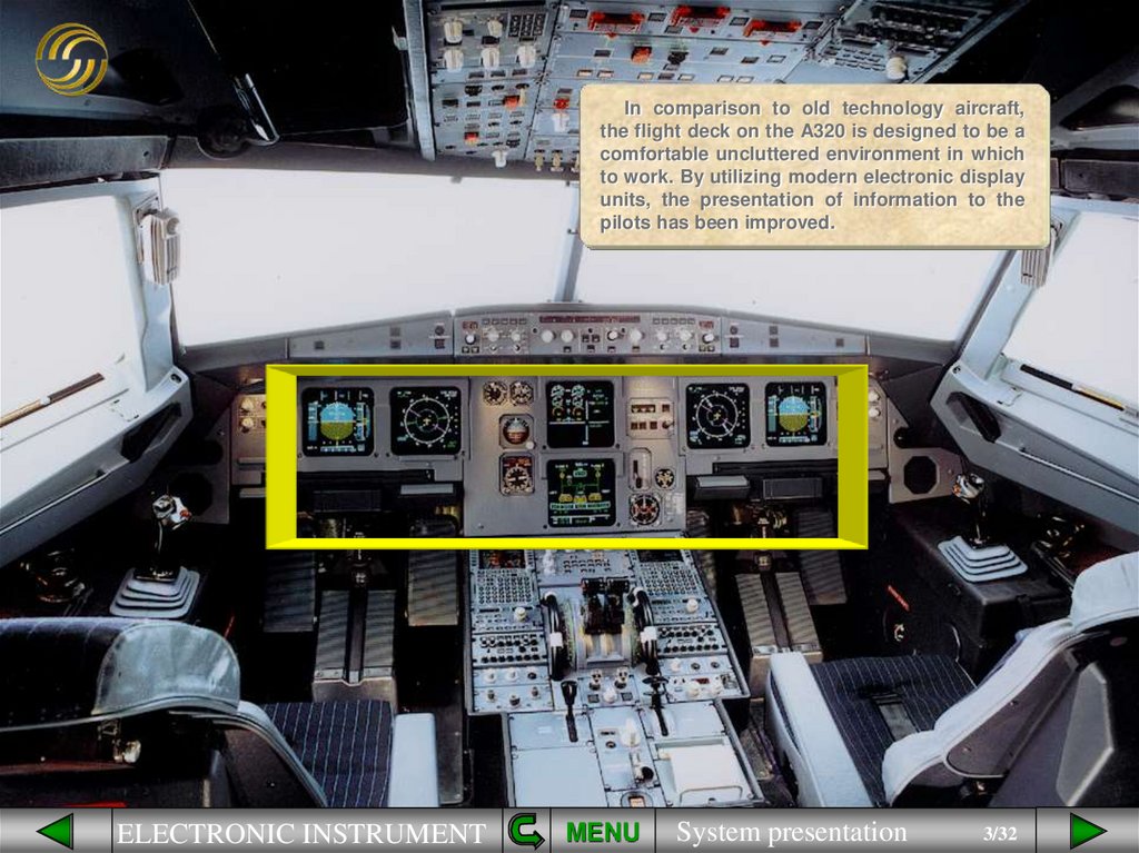
In comparison to old technology aircraft,the flight deck on the A320 is designed to be a
comfortable uncluttered environment in which
to work. By utilizing modern electronic display
units, the presentation of information to the
pilots has been improved.
ELECTRONIC INSTRUMENT
MENU
System presentation
3/32
4.
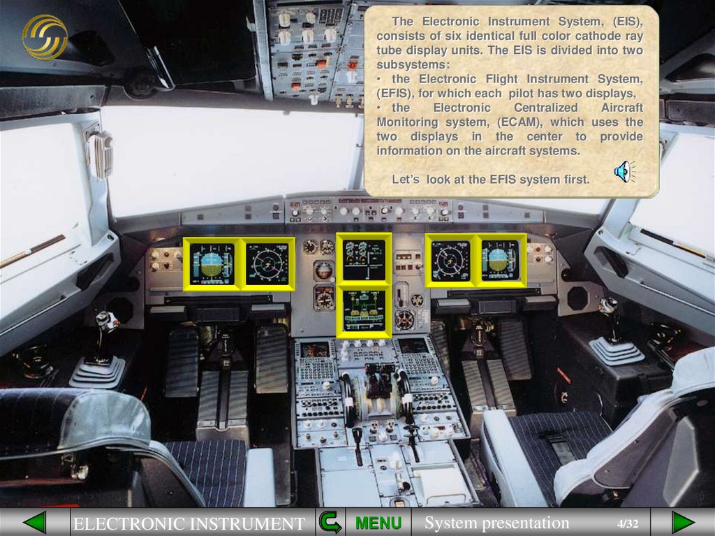
The Electronic Instrument System, (EIS),consists of six identical full color cathode ray
tube display units. The EIS is divided into two
subsystems:
• the Electronic Flight Instrument System,
(EFIS), for which each pilot has two displays,
• the
Electronic
Centralized
Aircraft
Monitoring system, (ECAM), which uses the
two displays in the center to provide
information on the aircraft systems.
Let’s look at the EFIS system first.
ELECTRONIC INSTRUMENT
MENU
System presentation
4/32
5.
Flight parameters are displayed on PrimaryFlight Displays (PFD) while Navigation data is
displayed on Navigation Displays (ND).
ELECTRONIC FLIGHT INSTRUMENT SYSTEM
PFD1
ND1
ELECTRONIC INSTRUMENT
ND2
MENU
System presentation
PFD2
5/32
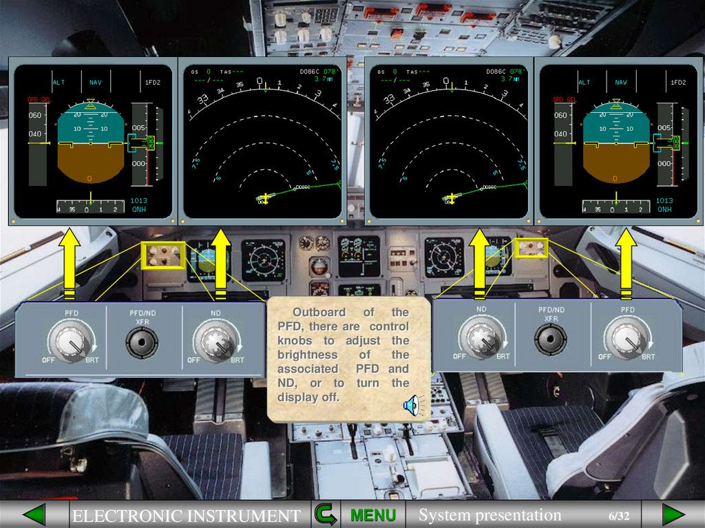
6.
Outboard of thePFD, there are control
knobs to adjust the
brightness
of
the
associated PFD and
ND, or to turn the
display off.
ELECTRONIC INSTRUMENT
MENU
System presentation
6/32
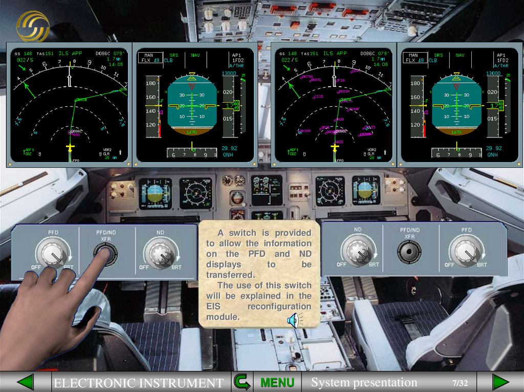
7.
A switch is providedto allow the information
on the PFD and ND
displays
to
be
transferred.
The use of this switch
will be explained in the
EIS
reconfiguration
module.
ELECTRONIC INSTRUMENT
MENU
System presentation
7/32
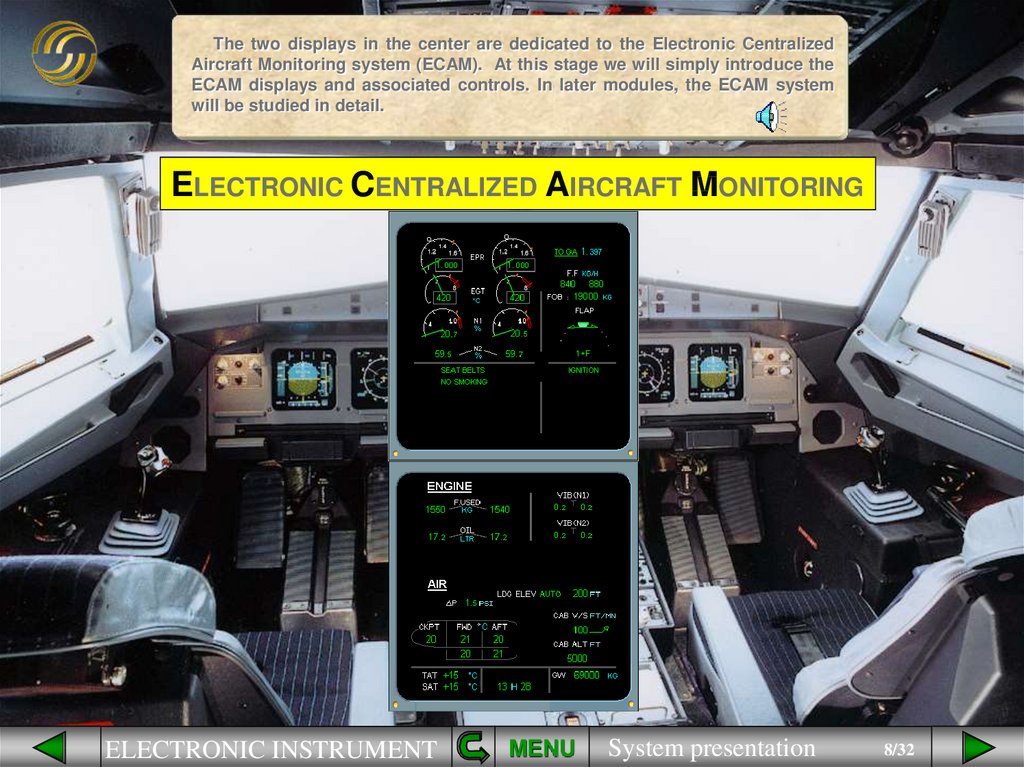
8.
The two displays in the center are dedicated to the Electronic CentralizedAircraft Monitoring system (ECAM). At this stage we will simply introduce the
ECAM displays and associated controls. In later modules, the ECAM system
will be studied in detail.
ELECTRONIC CENTRALIZED AIRCRAFT MONITORING
ELECTRONIC INSTRUMENT
MENU
System presentation
8/32
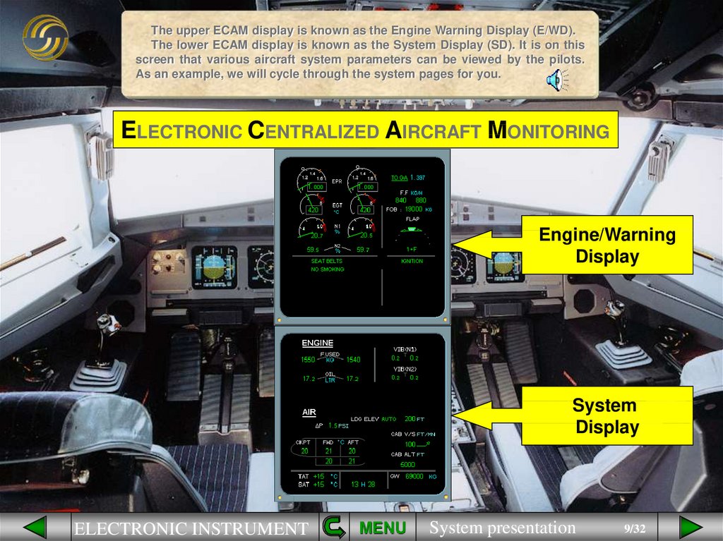
9.
The upper ECAM display is known as the Engine Warning Display (E/WD).The lower ECAM display is known as the System Display (SD). It is on this
screen that various aircraft system parameters can be viewed by the pilots.
As an example, we will cycle through the system pages for you.
ELECTRONIC CENTRALIZED AIRCRAFT MONITORING
Engine/Warning
Display
System
Display
ELECTRONIC INSTRUMENT
MENU
System presentation
9/32
10.
The presentation of system information is based on a “Need to Know”philosophy. This means that only the system information relevant to the
particular phase of flight is presented to the pilots. You will see this
demonstrated in the Normal and Abnormal operation modules.
ELECTRONIC CENTRALIZED AIRCRAFT MONITORING
Engine/Warning
Display
System
Display
ELECTRONIC INSTRUMENT
MENU
System presentation
10/32
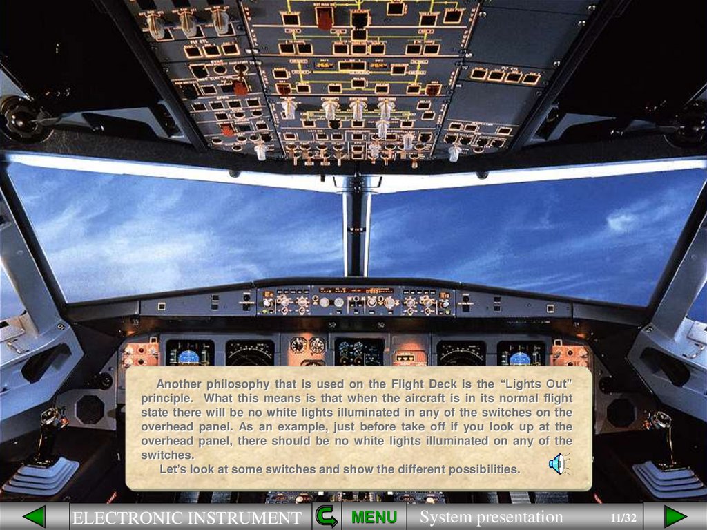
11.
Another philosophy that is used on the Flight Deck is the “Lights Out”principle. What this means is that when the aircraft is in its normal flight
state there will be no white lights illuminated in any of the switches on the
overhead panel. As an example, just before take off if you look up at the
overhead panel, there should be no white lights illuminated on any of the
switches.
Let’s look at some switches and show the different possibilities.
ELECTRONIC INSTRUMENT
MENU
System presentation
11/32
12.
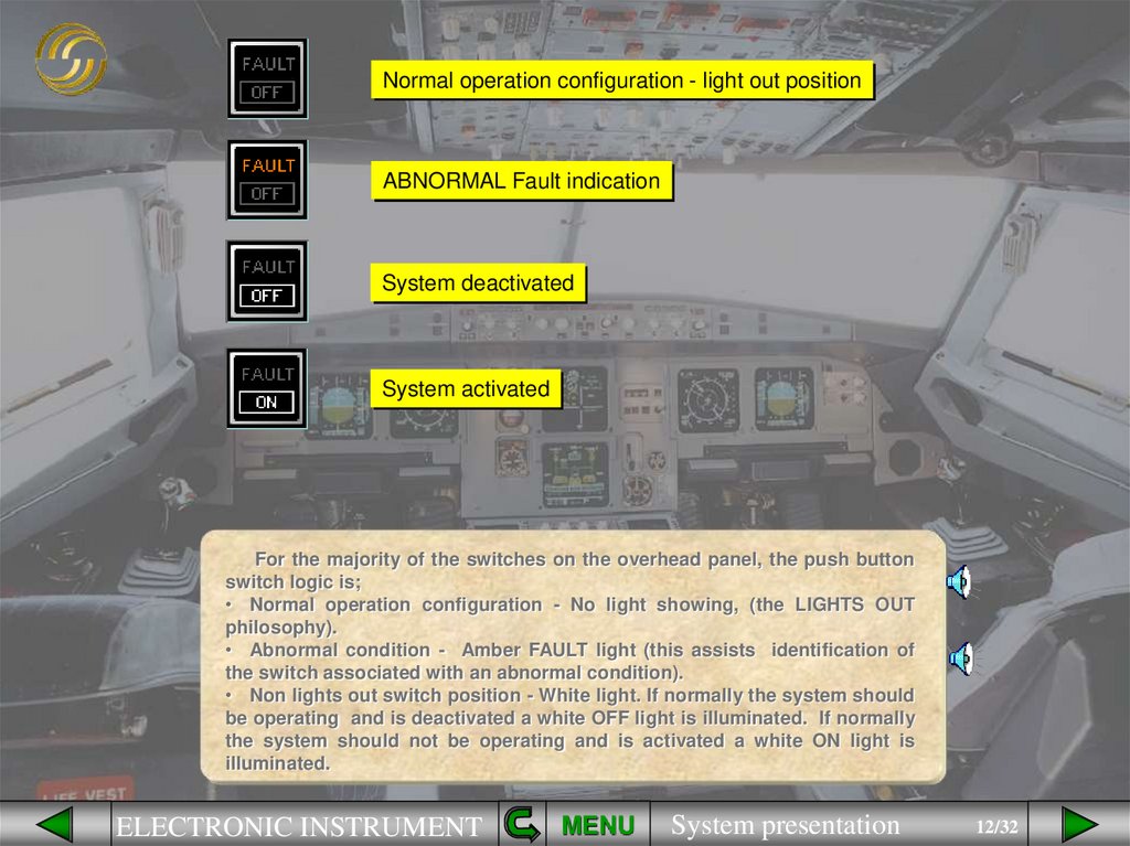
Normal operation configuration - light out positionABNORMAL Fault indication
System deactivated
System activated
For the majority of the switches on the overhead panel, the push button
switch logic is;
• Normal operation configuration - No light showing, (the LIGHTS OUT
philosophy).
• Abnormal condition - Amber FAULT light (this assists identification of
the switch associated with an abnormal condition).
• Non lights out switch position - White light. If normally the system should
be operating and is deactivated a white OFF light is illuminated. If normally
the system should not be operating and is activated a white ON light is
illuminated.
ELECTRONIC INSTRUMENT
MENU
System presentation
12/32
13.
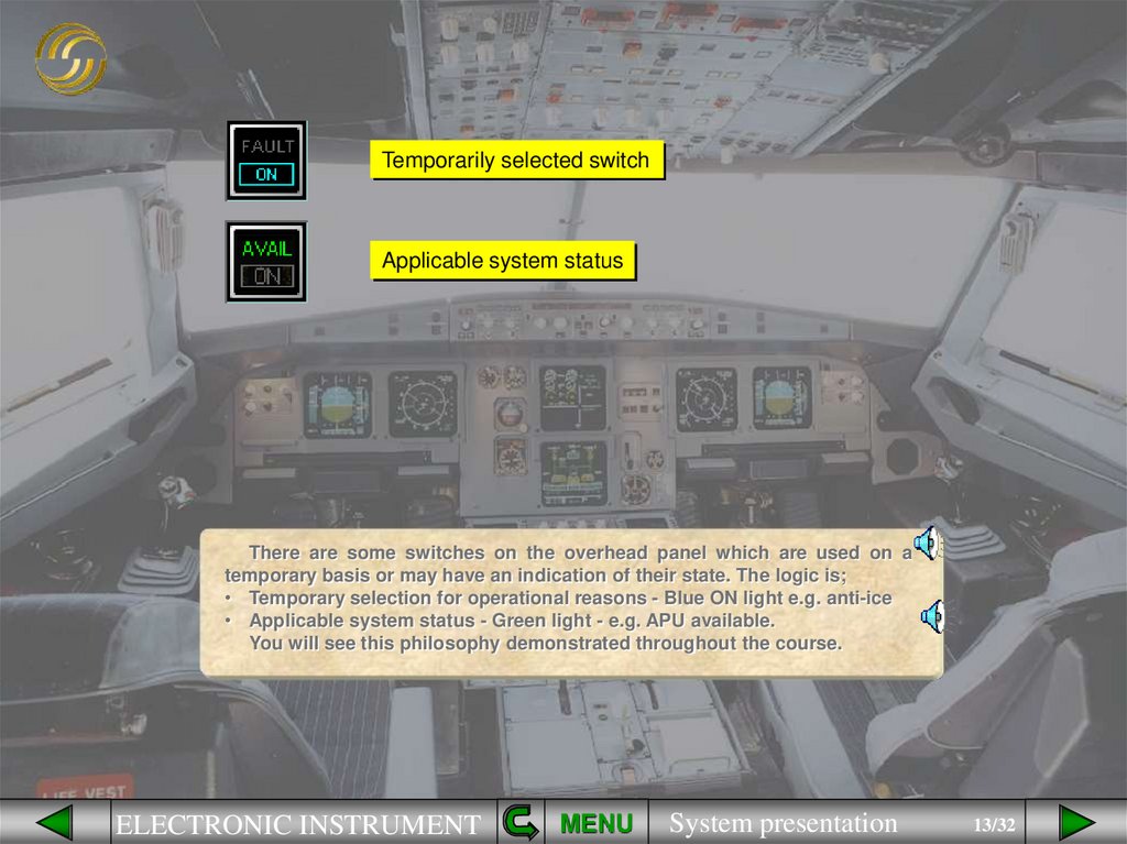
Temporarily selected switchApplicable system status
There are some switches on the overhead panel which are used on a
temporary basis or may have an indication of their state. The logic is;
• Temporary selection for operational reasons - Blue ON light e.g. anti-ice
• Applicable system status - Green light - e.g. APU available.
You will see this philosophy demonstrated throughout the course.
ELECTRONIC INSTRUMENT
MENU
System presentation
13/32
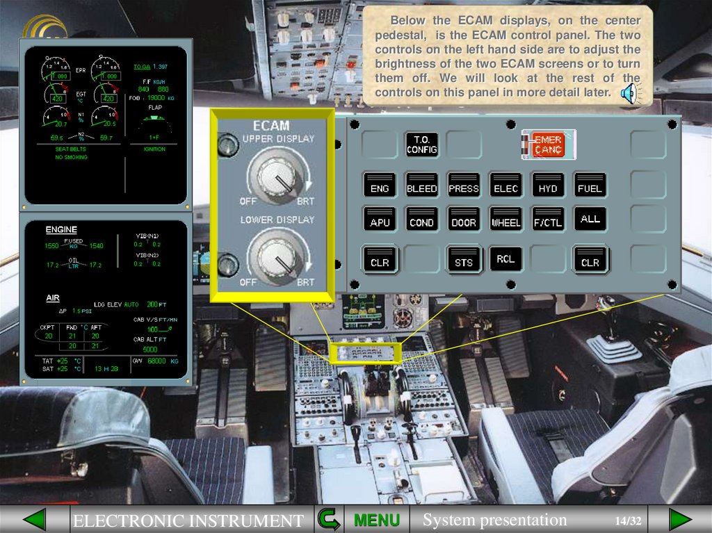
14.
Below the ECAM displays, on the centerpedestal, is the ECAM control panel. The two
controls on the left hand side are to adjust the
brightness of the two ECAM screens or to turn
them off. We will look at the rest of the
controls on this panel in more detail later.
ELECTRONIC INSTRUMENT
MENU
System presentation
14/32
15.
Just below the ECAM screens, on the pedestal, is a switching panel foruse in abnormal situations to restore data to the EFIS and ECAM displays.
You will use this panel in the EIS Reconfiguration module.
ELECTRONIC INSTRUMENT
MENU
System presentation
15/32
16.
In front of each pilot there are two attentiongetters, a red MASTER WARNING, and an
amber MASTER CAUTION. As a further means
of getting the pilots attention, there is a
loudspeaker on each side of the cockpit for
aural alerts and voice messages.
Note; The loudspeakers can also be used to
listen to ATC and the intercom.
ELECTRONIC INSTRUMENT
MENU
System presentation
16/32
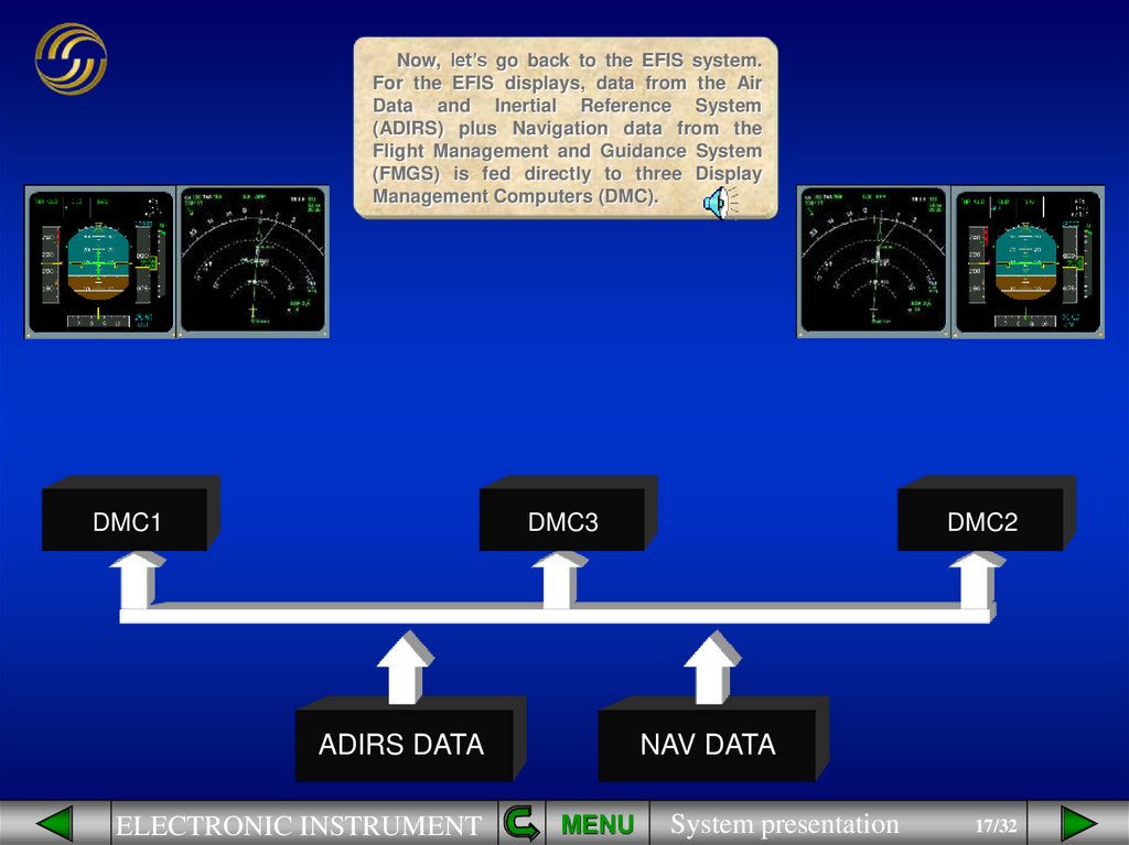
17.
Now, let’s go back to the EFIS system.For the EFIS displays, data from the Air
Data and Inertial Reference System
(ADIRS) plus Navigation data from the
Flight Management and Guidance System
(FMGS) is fed directly to three Display
Management Computers (DMC).
DMC1
DMC3
ADIRS DATA
ELECTRONIC INSTRUMENT
DMC2
NAV DATA
MENU
System presentation
17/32
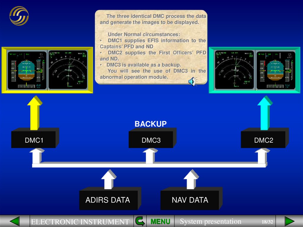
18.
The three identical DMC process the dataand generate the images to be displayed.
Under Normal circumstances:
• DMC1 supplies EFIS information to the
Captains’ PFD and ND
• DMC2 supplies the First Officers’ PFD
and ND.
• DMC3 is available as a backup.
You will see the use of DMC3 in the
abnormal operation module.
BACKUP
DMC1
DMC3
ADIRS DATA
ELECTRONIC INSTRUMENT
DMC2
NAV DATA
MENU
System presentation
18/32
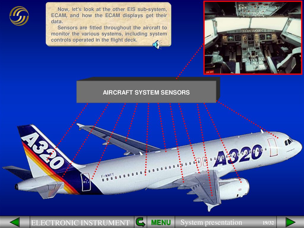
19.
Now, let’s look at the other EIS sub-system,ECAM, and how the ECAM displays get their
data.
Sensors are fitted throughout the aircraft to
monitor the various systems, including system
controls operated in the flight deck.
AIRCRAFT SYSTEM SENSORS
ELECTRONIC INSTRUMENT
MENU
System presentation
19/32
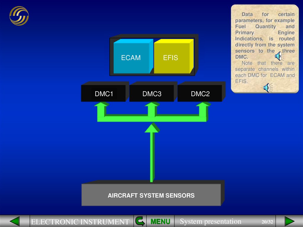
20.
Datafor
certain
parameters, for example
Fuel
Quantity
and
Primary
Engine
Indications, is routed
directly from the system
sensors to the
three
DMC.
Note that there are
separate channels within
each DMC for ECAM and
EFIS.
ECAM
DMC 3EFIS
DMC1
DMC3
DMC2
AIRCRAFT SYSTEM SENSORS
ELECTRONIC INSTRUMENT
MENU
System presentation
20/32
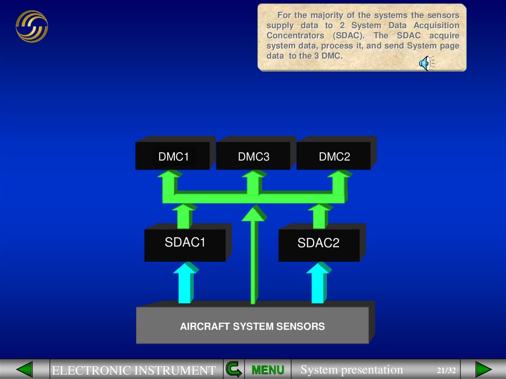
21.
For the majority of the systems the sensorssupply data to 2 System Data Acquisition
Concentrators (SDAC). The SDAC acquire
system data, process it, and send System page
data to the 3 DMC.
DMC1
DMC3
SDAC1
DMC2
SDAC2
AIRCRAFT SYSTEM SENSORS
ELECTRONIC INSTRUMENT
MENU
System presentation
21/32
22.
Normally:• DMC 1 supplies the E/WD,
• DMC2 supplies the SD,
• DMC 3 is available as a
backup.
BACKUP
DMC1
DMC3
SDAC1
DMC2
SDAC2
AIRCRAFT SYSTEM SENSORS
ELECTRONIC INSTRUMENT
MENU
System presentation
22/32
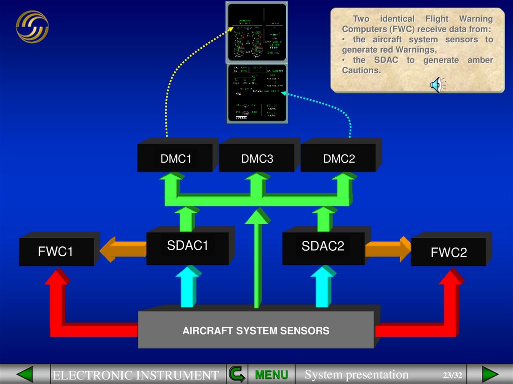
23.
Two identical Flight WarningComputers (FWC) receive data from:
• the aircraft system sensors to
generate red Warnings,
• the SDAC to generate amber
Cautions.
DMC1
FWC1
DMC3
SDAC1
DMC2
SDAC2
FWC2
AIRCRAFT SYSTEM SENSORS
ELECTRONIC INSTRUMENT
MENU
System presentation
23/32
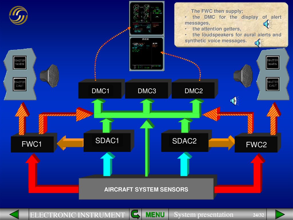
24.
The FWC then supply;• the DMC for the display of alert
messages,
• the attention getters,
• the loudspeakers for aural alerts and
synthetic voice messages.
DMC1
FWC1
DMC3
SDAC1
DMC2
SDAC2
FWC2
AIRCRAFT SYSTEM SENSORS
ELECTRONIC INSTRUMENT
MENU
System presentation
24/32
25.
DMC1FWC1
DMC3
SDAC1
DMC2
SDAC2
FWC2
AIRCRAFT SYSTEM SENSORS
ELECTRONIC INSTRUMENT
MENU
System presentation
25/32
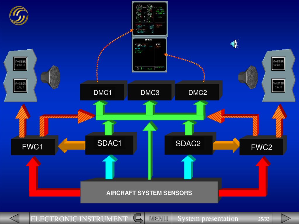
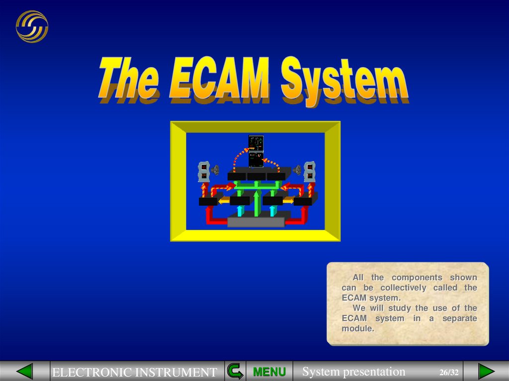
26.
All the components showncan be collectively called the
ECAM system.
We will study the use of the
ECAM system in a separate
module.
ELECTRONIC INSTRUMENT
MENU
System presentation
26/32
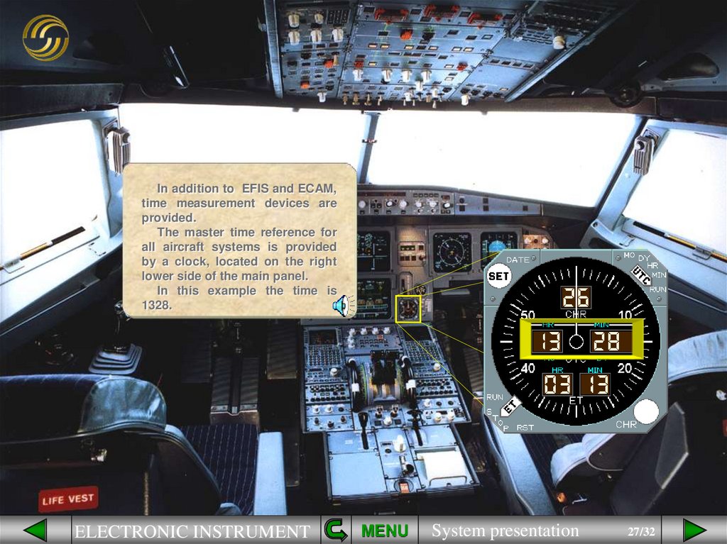
27.
In addition to EFIS and ECAM,time measurement devices are
provided.
The master time reference for
all aircraft systems is provided
by a clock, located on the right
lower side of the main panel.
In this example the time is
1328.
ELECTRONIC INSTRUMENT
MENU
System presentation
27/32
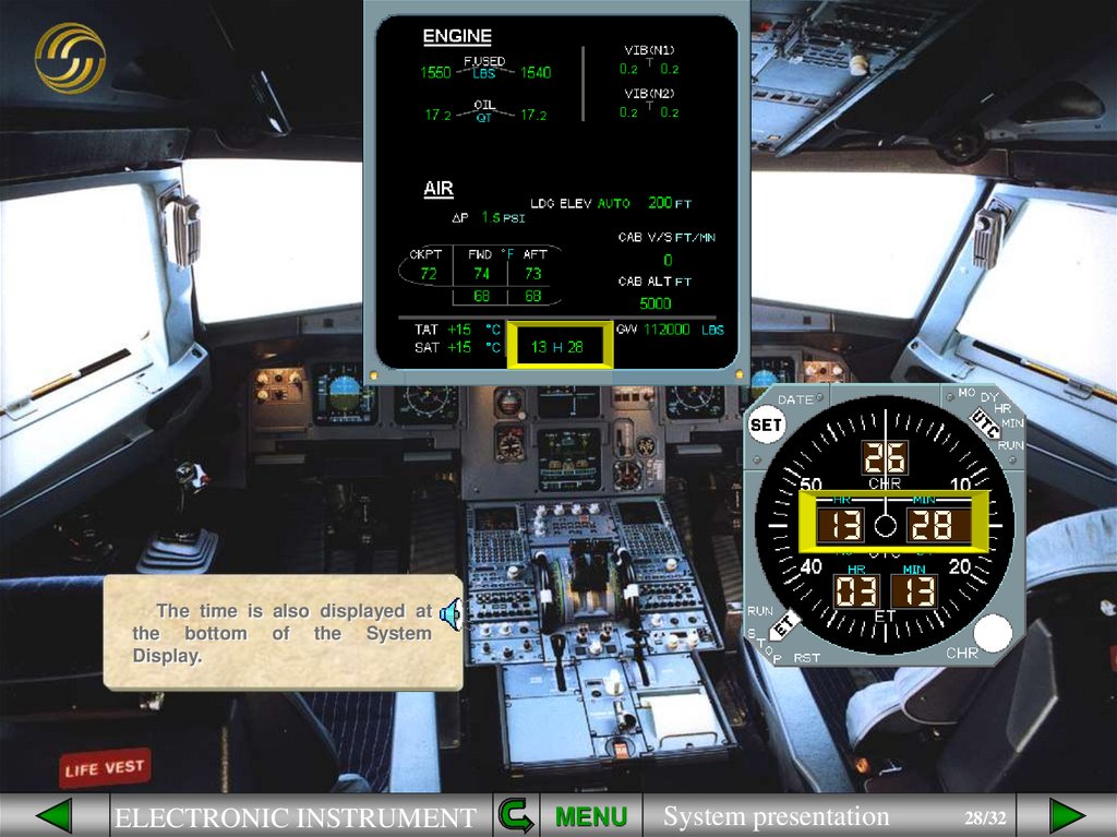
28.
The time is also displayed atthe bottom of the System
Display.
ELECTRONIC INSTRUMENT
MENU
System presentation
28/32
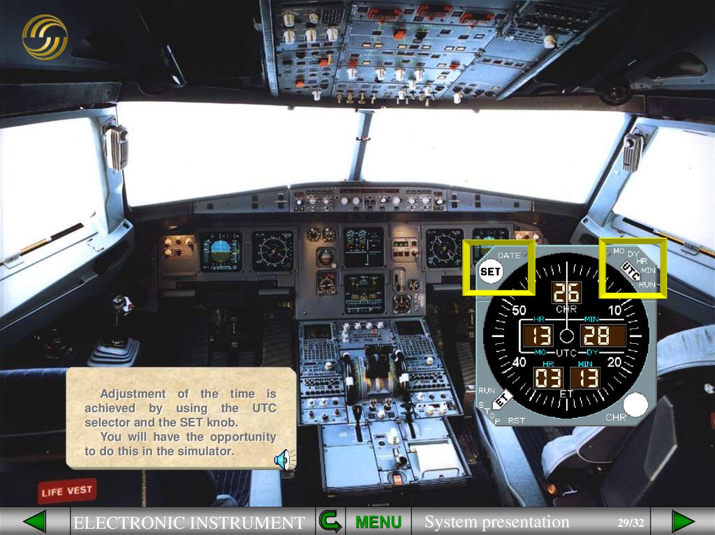
29.
Adjustment of the time isachieved by using the UTC
selector and the SET knob.
You will have the opportunity
to do this in the simulator.
ELECTRONIC INSTRUMENT
MENU
System presentation
29/32
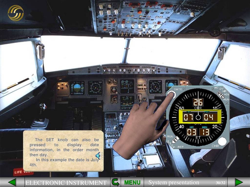
30.
The SET knob can also bepressed
to
display
date
information, in the order month
then day.
In this example the date is July
4th.
ELECTRONIC INSTRUMENT
MENU
System presentation
30/32
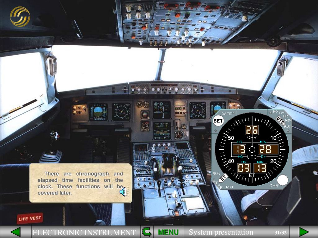
31.
There are chronograph andelapsed time facilities on the
clock. These functions will be
covered later.
ELECTRONIC INSTRUMENT
MENU
System presentation
31/32
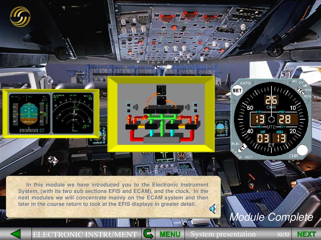
32.
In this module we have introduced you to the Electronic InstrumentSystem, (with its two sub sections EFIS and ECAM), and the clock. In the
next modules we will concentrate mainly on the ECAM system and then
later in the course return to look at the EFIS displays in greater detail.
Module Complete
ELECTRONIC INSTRUMENT
MENU
System presentation
32/32
NEXT
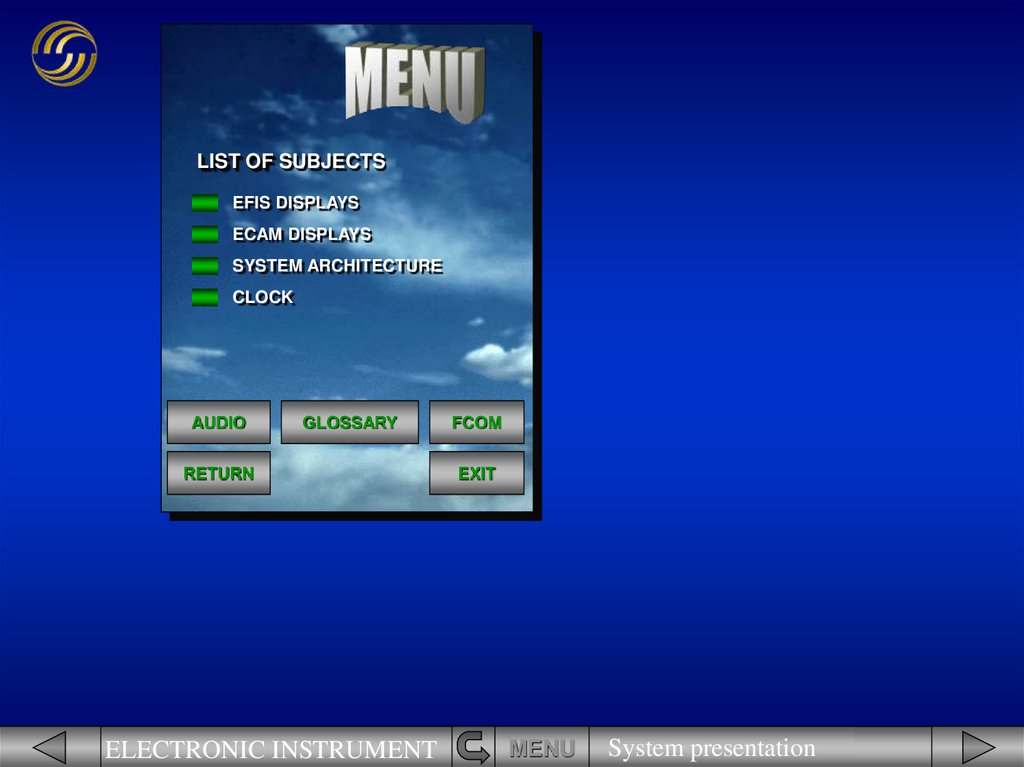
33.
LIST OF SUBJECTSEFIS DISPLAYS
ECAM DISPLAYS
SYSTEM ARCHITECTURE
CLOCK
AUDIO
GLOSSARY
RETURN
ELECTRONIC INSTRUMENT
FCOM
EXIT
MENU
System presentation
33/32