


 electronics
Similar presentations:


 Wireless Audio - Soundbar ’2017 SAMSUNG ELECTRONICS CO.,LTD. VD R&D GROUP")


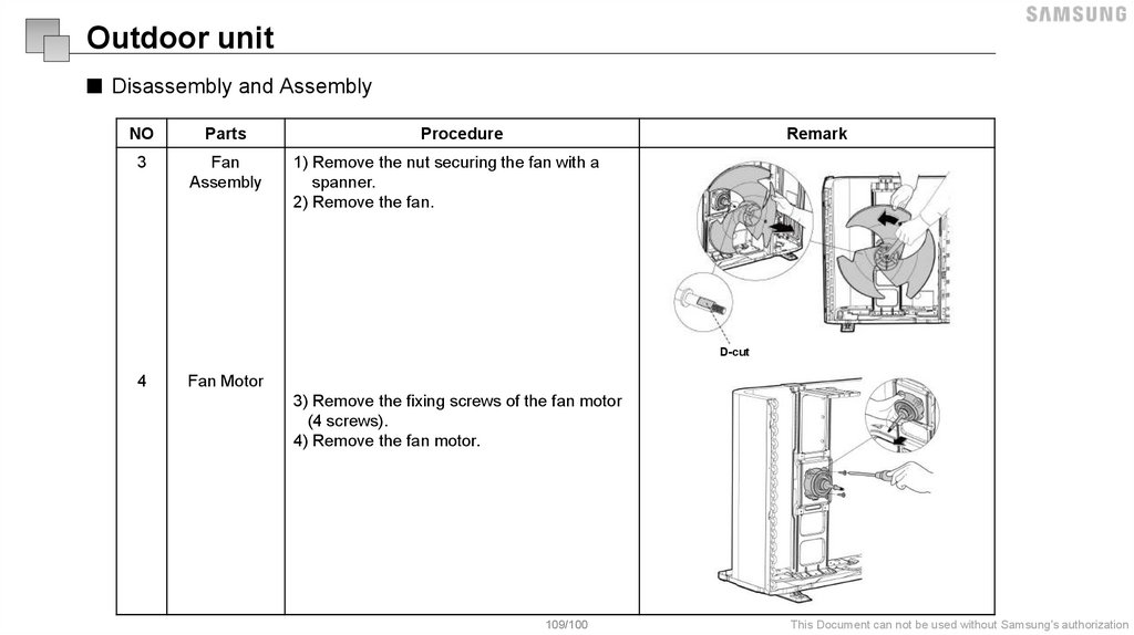
Samsung Electronics
1.
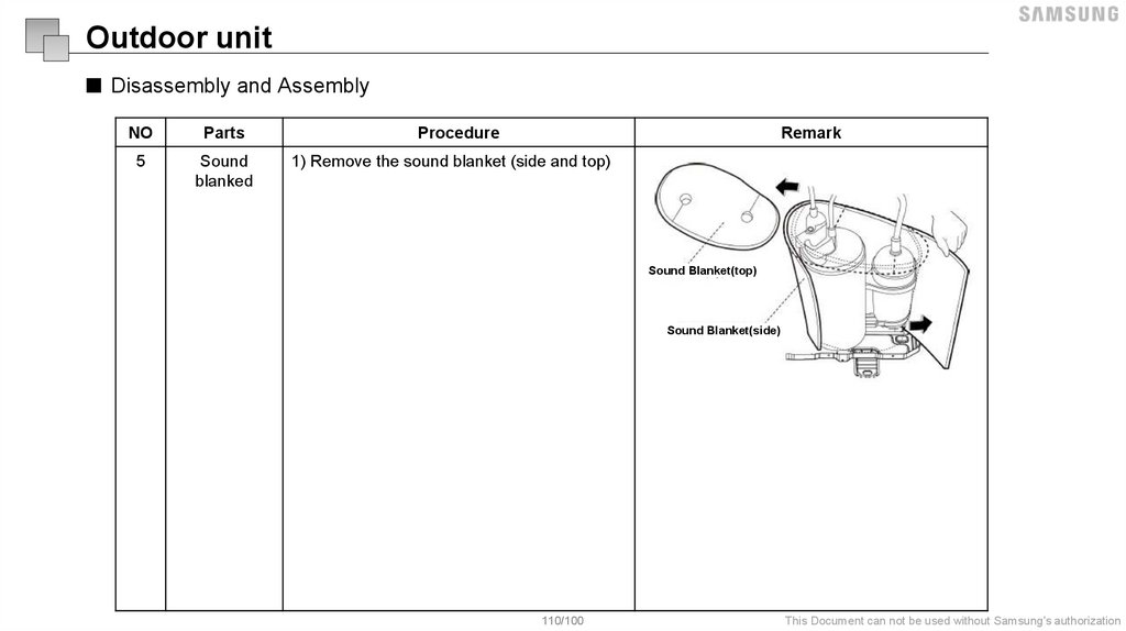
Samsung ElectronicsThis Training Manual is a property of Samsung Electronics Co.,Ltd.
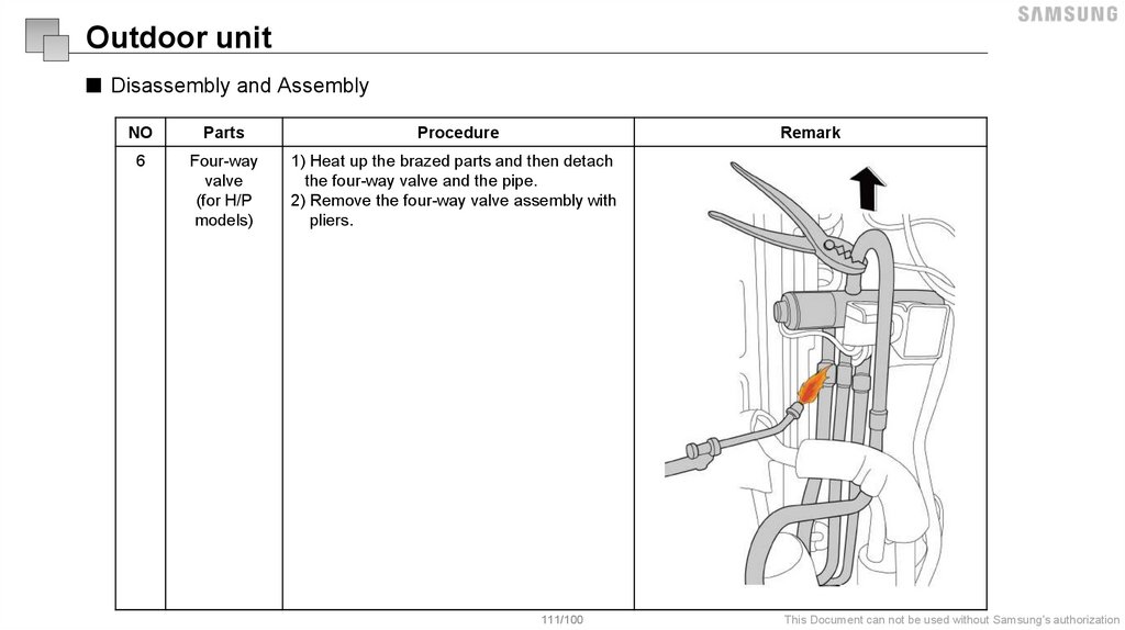
Any unauthorized use of Manual can be punished under applicable International and/or domestic law.
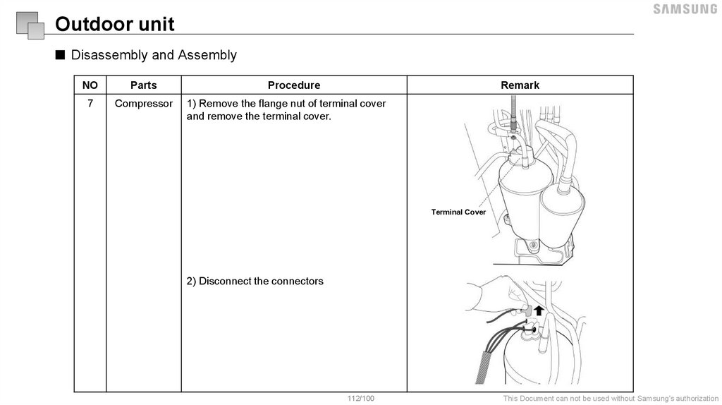
2.
Modification historyDate
04 June 2019
Ver.
1.0
Modifier
OOO, OOO
Detail
Remarks
- New
2/100
This Document can not be used without Samsung's authorization
3.
4.
Line up5.
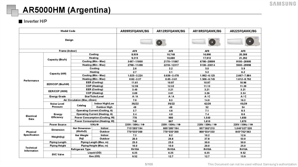
AR5000HM (Argentina)■ Inverter H/P
Model Code
AR09RSFQAWK/BG
AR12RSFQAWK/BG
AR18RSFQAWK/BG
AR22SFQAWK/BG
AF9
8,939
9,315
3497~11000
2798~11498
2.6
2.7
1.025~3.224
0.82~3.37
11.61
12.59
3.40
3.69
A/A
7.0
38/22
49
3.7
3.4
770
740
220V / 50Hz / 1Φ
715*285*194
770*555*300
7.3
26.0
25.0
10.0
R410A
6.35
9.52
AF9
10,748
10,680
2170~11867
2218~12317
3.2
3.1
0.636~3.478
0.65~3.61
10.97
12.32
3.21
3.61
A/A
9.3
39/22
49
4.6
4.0
980
867
220V / 50Hz / 1Φ
805*285*194
770*555*300
8.2
26.8
25.0
10.0
R410A
6.35
12.7
AF9
16,890
17,913
6798~20899
5138~23014
5.0
5.3
1.992~6.125
1.506~6.745
10.97
11.13
3.21
3.26
A/C
14.0
42/26
52
7.1
7.4
1,540
1,610
220V / 50Hz / 1Φ
957*302*213
800*554*333
10.2
37.8
30.0
20.0
R410A
6.35
12.7
AF9
20,268
21,292
9100~26900
5500~29998
5.9
6.2
2.667~7.884
1.612~8.792
10.96
11.39
3.21
3.34
A/C
16.3
45/29
54
8.5
8.6
1,850
1,870
220V / 50Hz / 1Φ
1,040*327*220
845*702*363
12.6
53.0
50.0
25.0
R410A
9.52
15.9
Design
Frame (Indoor)
Performance
Electrical
Data
Physical
Specification
Technical
Information
Cooling
Heating
Capacity (Btu/h)
Cooling (Min - Max)
Heating (Min - Max)
Cooling
Heating
Capacity (kW)
Cooling (Min - Max)
Heating (Min - Max)
EER (Cooling)
EER/COP (Btu/hW)
COP (Heating)
EER (Cooling)
EER/COP (W/W)
COP (Heating)
Energy Grade
Star/Ticks/Level
Air Circulation (Max, ㎥/min)
Indoor High/Low
Noise Level
Catalog
Pressure
Outdoor High
Operating Current (Cooling, A)
Operating Current (Heating, A)
Energy
Efficiency
Power Consumption (Cooling, W)
Power Consumption (Heating, W)
Power Source
V/Hz/Φ
Indoor
Net Dimension
Dimension
(WxHxD)
Outdoor
Indoor
Net Weight
Weight(kg)
(kg)
Outdoor
Piping Length
Piping Length (Max, m)
Piping Height
Piping Height (Max, m)
Refrigerant Type
Liquid (OD)
SVC Valve
Gas (OD)
5/100
This Document can not be used without Samsung's authorization
6.
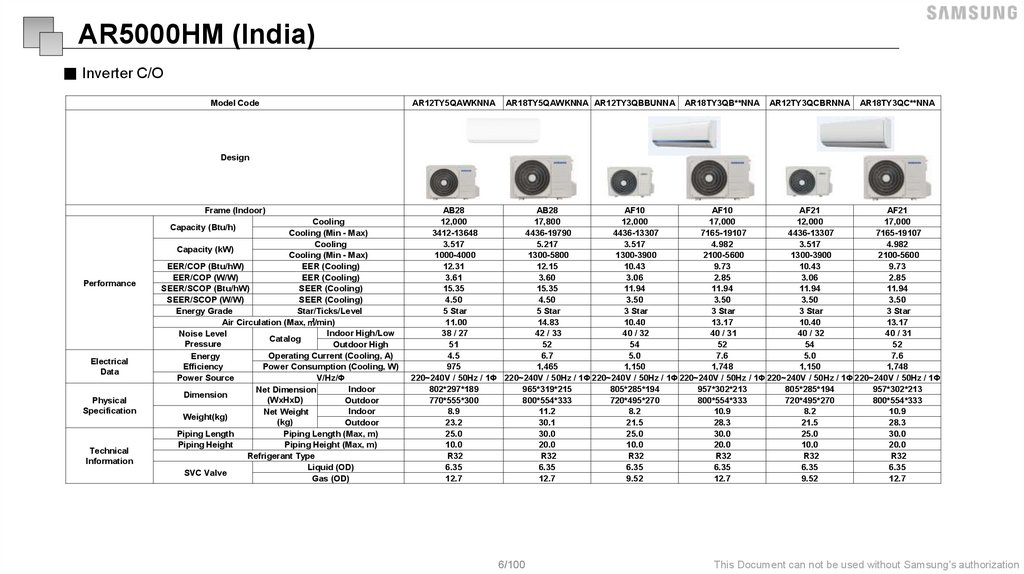
AR5000HM (India)■ Inverter C/O
Model Code
AR12TY5QAWKNNA
AR18TY5QAWKNNA AR12TY3QBBUNNA
AR18TY3QB**NNA
AR12TY3QCBRNNA
AR18TY3QC**NNA
Design
Frame (Indoor)
Performance
Electrical
Data
Physical
Specification
Technical
Information
Cooling
Capacity (Btu/h)
Cooling (Min - Max)
Cooling
Capacity (kW)
Cooling (Min - Max)
EER/COP (Btu/hW)
EER (Cooling)
EER/COP (W/W)
EER (Cooling)
SEER/SCOP (Btu/hW)
SEER (Cooling)
SEER/SCOP (W/W)
SEER (Cooling)
Energy Grade
Star/Ticks/Level
Air Circulation (Max, ㎥/min)
Indoor High/Low
Noise Level
Catalog
Pressure
Outdoor High
Operating Current (Cooling, A)
Energy
Efficiency
Power Consumption (Cooling, W)
Power Source
V/Hz/Φ
Indoor
Net Dimension
Dimension
(WxHxD)
Outdoor
Indoor
Net Weight
Weight(kg)
(kg)
Outdoor
Piping Length
Piping Length (Max, m)
Piping Height
Piping Height (Max, m)
Refrigerant Type
Liquid (OD)
SVC Valve
Gas (OD)
AB28
AB28
AF10
AF10
AF21
AF21
12,000
17,800
12,000
17,000
12,000
17,000
3412-13648
4436-19790
4436-13307
7165-19107
4436-13307
7165-19107
3.517
5.217
3.517
4.982
3.517
4.982
1000-4000
1300-5800
1300-3900
2100-5600
1300-3900
2100-5600
12.31
12.15
10.43
9.73
10.43
9.73
3.61
3.60
3.06
2.85
3.06
2.85
15.35
15.35
11.94
11.94
11.94
11.94
4.50
4.50
3.50
3.50
3.50
3.50
5 Star
5 Star
3 Star
3 Star
3 Star
3 Star
11.00
14.83
10.40
13.17
10.40
13.17
38 / 27
42 / 33
40 / 32
40 / 31
40 / 32
40 / 31
51
52
54
52
54
52
4.5
6.7
5.0
7.6
5.0
7.6
975
1,465
1,150
1,748
1,150
1,748
220~240V / 50Hz / 1Φ 220~240V / 50Hz / 1Φ 220~240V / 50Hz / 1Φ 220~240V / 50Hz / 1Φ 220~240V / 50Hz / 1Φ 220~240V / 50Hz / 1Φ
802*297*189
965*319*215
805*285*194
957*302*213
805*285*194
957*302*213
770*555*300
800*554*333
720*495*270
800*554*333
720*495*270
800*554*333
8.9
11.2
8.2
10.9
8.2
10.9
23.2
30.1
21.5
28.3
21.5
28.3
25.0
30.0
25.0
30.0
25.0
30.0
10.0
20.0
10.0
20.0
10.0
20.0
R32
R32
R32
R32
R32
R32
6.35
6.35
6.35
6.35
6.35
6.35
12.7
12.7
9.52
12.7
9.52
12.7
6/100
This Document can not be used without Samsung's authorization
7.
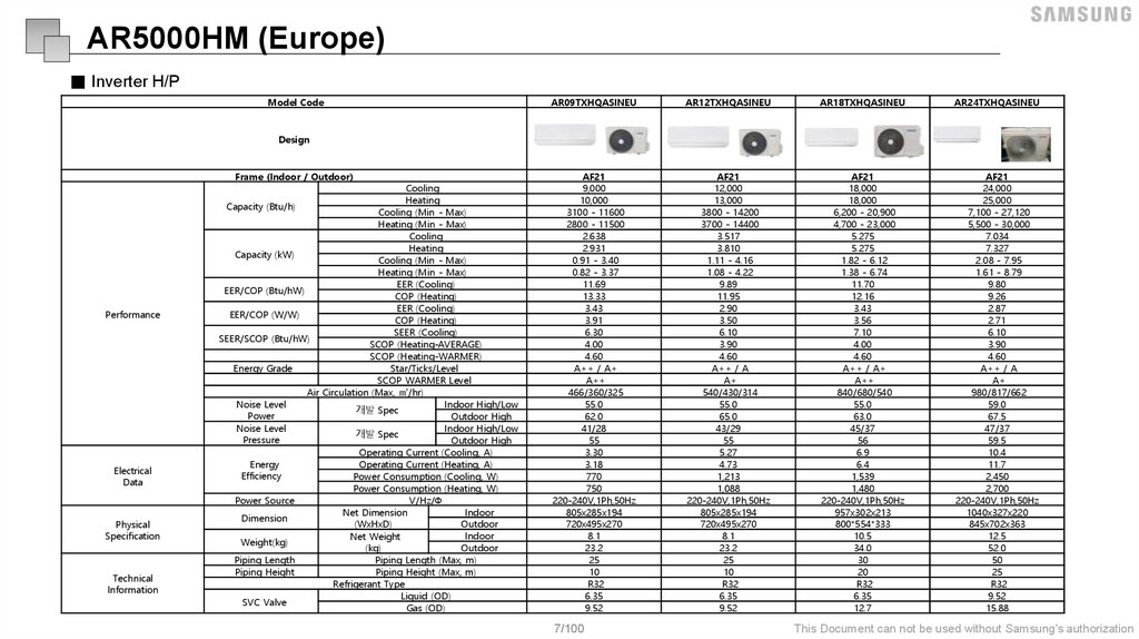
AR5000HM (Europe)■ Inverter H/P
Model Code
AR09TXHQASINEU
AR12TXHQASINEU
AR18TXHQASINEU
AR24TXHQASINEU
AF21
9,000
10,000
3100 - 11600
2800 - 11500
2.638
2.931
0.91 - 3.40
0.82 - 3.37
11.69
13.33
3.43
3.91
6.30
4.00
4.60
A++ / A+
A++
466/360/325
55.0
62.0
41/28
55
3.30
3.18
770
750
220-240V,1Ph,50Hz
805x285x194
720x495x270
8.1
23.2
25
10
R32
6.35
9.52
AF21
12,000
13,000
3800 - 14200
3700 - 14400
3.517
3.810
1.11 - 4.16
1.08 - 4.22
9.89
11.95
2.90
3.50
6.10
3.90
4.60
A++ / A
A+
540/430/314
55.0
65.0
43/29
55
5.27
4.73
1,213
1,088
220-240V,1Ph,50Hz
805x285x194
720x495x270
8.1
23.2
25
10
R32
6.35
9.52
AF21
18,000
18,000
6,200 - 20,900
4,700 - 23,000
5.275
5.275
1.82 - 6.12
1.38 - 6.74
11.70
12.16
3.43
3.56
7.10
4.00
4.60
A++ / A+
A++
840/680/540
55.0
63.0
45/37
56
6.9
6.4
1,539
1,480
220-240V,1Ph,50Hz
957x302x213
800*554*333
10.5
34.0
30
20
R32
6.35
12.7
AF21
24,000
25,000
7,100 - 27,120
5,500 - 30,000
7.034
7.327
2.08 - 7.95
1.61 - 8.79
9.80
9.26
2.87
2.71
6.10
3.90
4.60
A++ / A
A+
980/817/662
59.0
67.5
47/37
59.5
10.4
11.7
2,450
2,700
220-240V,1Ph,50Hz
1040x327x220
845x702x363
12.5
52.0
50
25
R32
9.52
15.88
Design
Frame (Indoor / Outdoor)
Performance
Electrical
Data
Physical
Specification
Technical
Information
Cooling
Heating
Capacity (Btu/h)
Cooling (Min - Max)
Heating (Min - Max)
Cooling
Heating
Capacity (kW)
Cooling (Min - Max)
Heating (Min - Max)
EER (Cooling)
EER/COP (Btu/hW)
COP (Heating)
EER (Cooling)
EER/COP (W/W)
COP (Heating)
SEER (Cooling)
SEER/SCOP (Btu/hW)
SCOP (Heating-AVERAGE)
SCOP (Heating-WARMER)
Energy Grade
Star/Ticks/Level
SCOP WARMER Level
Air Circulation (Max, ㎥/hr)
Indoor High/Low
Noise Level
개발 Spec
Power
Outdoor High
Indoor High/Low
Noise Level
개발 Spec
Pressure
Outdoor High
Operating Current (Cooling, A)
Operating Current (Heating, A)
Energy
Efficiency
Power Consumption (Cooling, W)
Power Consumption (Heating, W)
Power Source
V/Hz/Φ
Indoor
Net Dimension
Dimension
(WxHxD)
Outdoor
Indoor
Net Weight
Weight(kg)
(kg)
Outdoor
Piping Length
Piping Length (Max, m)
Piping Height
Piping Height (Max, m)
Refrigerant Type
Liquid (OD)
SVC Valve
Gas (OD)
7/100
This Document can not be used without Samsung's authorization
8.
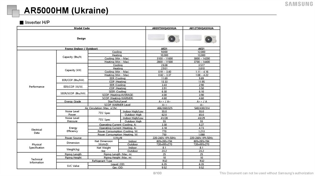
AR5000HM (Ukraine)■ Inverter H/P
Model Code
AR09TXHQASINUA
AR12TXHQASINUA
AF21
9,000
10,000
3100 - 11600
2800 - 11500
2.638
2.931
0.91 - 3.40
0.82 - 3.37
11.69
13.33
3.43
3.91
6.30
4.00
4.60
A++ / A+
A++
466/360/325
55.0
62.0
41/28
55
3.30
3.18
770
750
220-240V,1Ph,50Hz
805x285x194
720x495x270
8.1
23.2
25
10
R32
6.35
9.52
AF21
12,000
13,000
3800 - 14200
3700 - 14400
3.517
3.810
1.11 - 4.16
1.08 - 4.22
9.89
11.95
2.90
3.50
6.10
3.90
4.60
A++ / A
A+
540/430/314
55.0
65.0
43/29
55
5.27
4.73
1,213
1,088
220-240V,1Ph,50Hz
805x285x194
720x495x270
8.1
23.2
25
10
R32
6.35
9.52
Design
Frame (Indoor / Outdoor)
Performance
Electrical
Data
Physical
Specification
Technical
Information
Cooling
Heating
Capacity (Btu/h)
Cooling (Min - Max)
Heating (Min - Max)
Cooling
Heating
Capacity (kW)
Cooling (Min - Max)
Heating (Min - Max)
EER (Cooling)
EER/COP (Btu/hW)
COP (Heating)
EER (Cooling)
EER/COP (W/W)
COP (Heating)
SEER (Cooling)
SEER/SCOP (Btu/hW)
SCOP (Heating-AVERAGE)
SCOP (Heating-WARMER)
Energy Grade
Star/Ticks/Level
SCOP WARMER Level
Air Circulation (Max, ㎥/hr)
Indoor High/Low
Noise Level
개발 Spec
Power
Outdoor High
Indoor High/Low
Noise Level
개발 Spec
Pressure
Outdoor High
Operating Current (Cooling, A)
Operating Current (Heating, A)
Energy
Efficiency
Power Consumption (Cooling, W)
Power Consumption (Heating, W)
Power Source
V/Hz/Φ
Indoor
Net Dimension
Dimension
(WxHxD)
Outdoor
Indoor
Net Weight
Weight(kg)
(kg)
Outdoor
Piping Length
Piping Length (Max, m)
Piping Height
Piping Height (Max, m)
Refrigerant Type
Liquid (OD)
SVC Valve
Gas (OD)
8/100
This Document can not be used without Samsung's authorization
9.
Feature10.
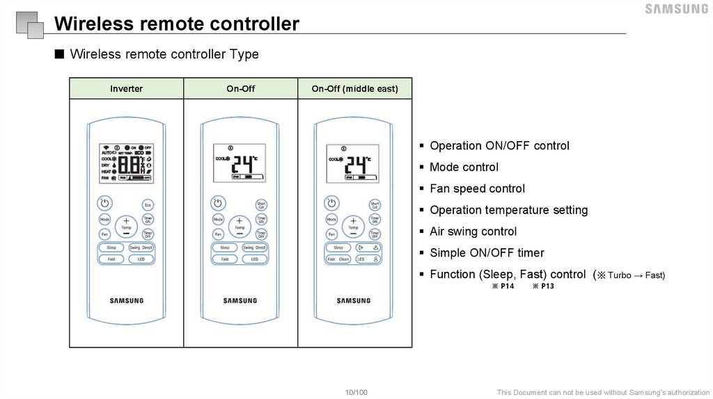
Wireless remote controller■ Wireless remote controller Type
Inverter
On-Off
On-Off (middle east)
Operation ON/OFF control
Mode control
Fan speed control
Operation temperature setting
Air swing control
Simple ON/OFF timer
Function (Sleep, Fast) control (※ Turbo → Fast)
※ P14
10/100
※ P13
This Document can not be used without Samsung's authorization
11.
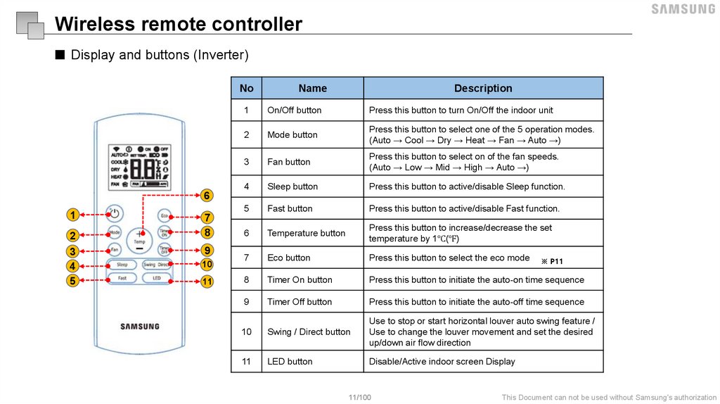
Wireless remote controller■ Display and buttons (Inverter)
No
Name
Description
1
On/Off button
Press this button to turn On/Off the indoor unit
2
Mode button
Press this button to select one of the 5 operation modes.
(Auto → Cool → Dry → Heat → Fan → Auto →)
3
Fan button
Press this button to select on of the fan speeds.
(Auto → Low → Mid → High → Auto →)
4
Sleep button
Press this button to active/disable Sleep function.
5
Fast button
Press this button to active/disable Fast function.
6
Temperature button
Press this button to increase/decrease the set
temperature by 1℃(℉)
7
Eco button
Press this button to select the eco mode
8
Timer On button
Press this button to initiate the auto-on time sequence
9
Timer Off button
Press this button to initiate the auto-off time sequence
10
Swing / Direct button
Use to stop or start horizontal louver auto swing feature /
Use to change the louver movement and set the desired
up/down air flow direction
11
LED button
Disable/Active indoor screen Display
6
1
2
3
4
5
7
8
9
10
11
11/100
※ P11
This Document can not be used without Samsung's authorization
12.
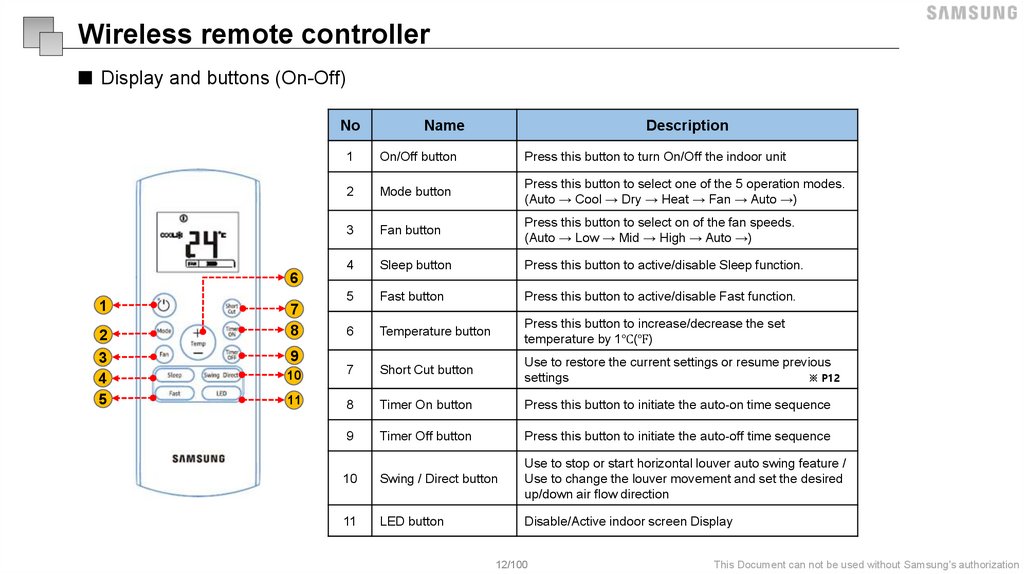
Wireless remote controller■ Display and buttons (On-Off)
No
Name
Description
1
On/Off button
Press this button to turn On/Off the indoor unit
2
Mode button
Press this button to select one of the 5 operation modes.
(Auto → Cool → Dry → Heat → Fan → Auto →)
3
Fan button
Press this button to select on of the fan speeds.
(Auto → Low → Mid → High → Auto →)
4
Sleep button
Press this button to active/disable Sleep function.
5
Fast button
Press this button to active/disable Fast function.
6
Temperature button
Press this button to increase/decrease the set
temperature by 1℃(℉)
10
7
Short Cut button
Use to restore the current settings or resume previous
settings
※ P12
11
8
Timer On button
Press this button to initiate the auto-on time sequence
9
Timer Off button
Press this button to initiate the auto-off time sequence
10
Swing / Direct button
Use to stop or start horizontal louver auto swing feature /
Use to change the louver movement and set the desired
up/down air flow direction
11
LED button
Disable/Active indoor screen Display
6
1
2
3
4
5
7
8
9
12/100
This Document can not be used without Samsung's authorization
13.
■ Eco (Inverter Model)● Used to enter the energy efficient mode.
● Under cooling mode, press this button, the remote controller will adjust the temperature automatically to 24 ℃,
fan speed of Auto to save energy (but only if the set temperature is less than 24 ℃). If the set temperature is
between 24 ℃ and 30 ℃, press the ECO button, the fan speed will change to Auto, the set temperature will
remain unchanged.
NOTE
● Press the FAST and SLEEP button, modifying the mode or adjusting the set temperature to less than
24 ℃ will stop ECO operation
● Under ECO operation, the set temperature should be 24 ℃ or more. It may result in insufficient cooling.
If you feel uncomfortable, just press the ECO button again to stop it.
13/100
This Document can not be used without Samsung's authorization
14.
■ Shortcut (On-Off Model)● Used to restore the current settings or resume previous settings.
● On the first time connecting to the power. if push the SHORTCUT button, the unit will operate on AUTO mode,
26 ℃, and fan speed is Auto.
● Push this button when remote controller is on, the system will automatically revert back to the previous
settings including operating mode, setting temperature, fan speed level and sleep feature(if activated).
● If pushing more than 2 seconds, the system will automatically restore the current operation settings including
operating mode, setting temperature, fan speed level and sleep feature(if activated ).
14/100
This Document can not be used without Samsung's authorization
15.
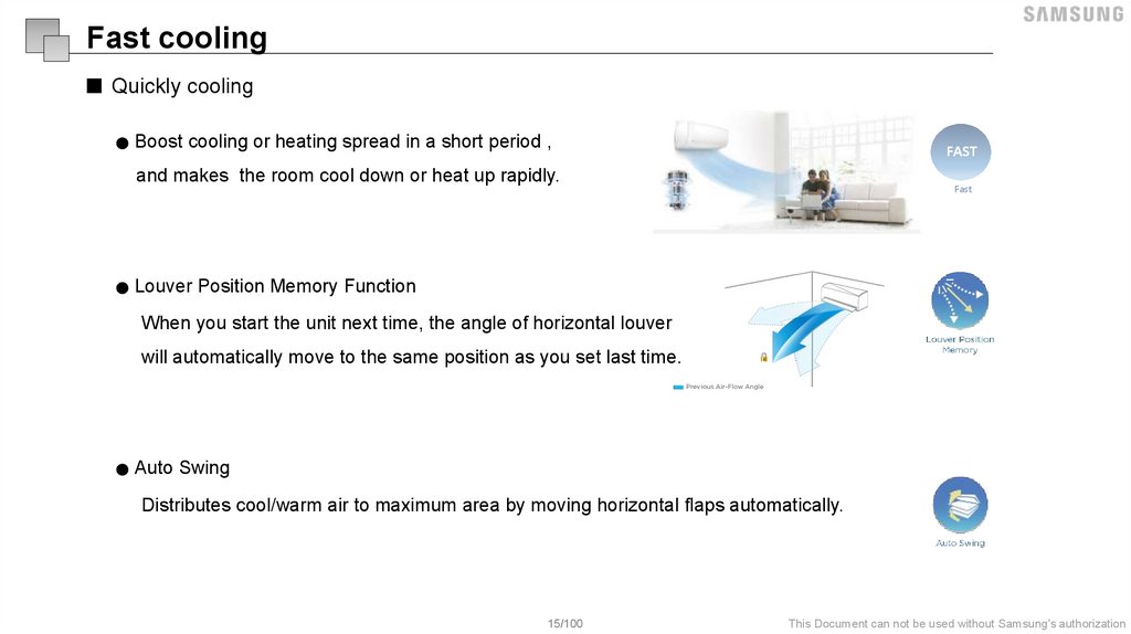
Fast cooling■ Quickly cooling
● Boost cooling or heating spread in a short period ,
FAST
and makes the room cool down or heat up rapidly.
Fast
● Louver Position Memory Function
When you start the unit next time, the angle of horizontal louver
will automatically move to the same position as you set last time.
● Auto Swing
Distributes cool/warm air to maximum area by moving horizontal flaps automatically.
15/100
This Document can not be used without Samsung's authorization
16.
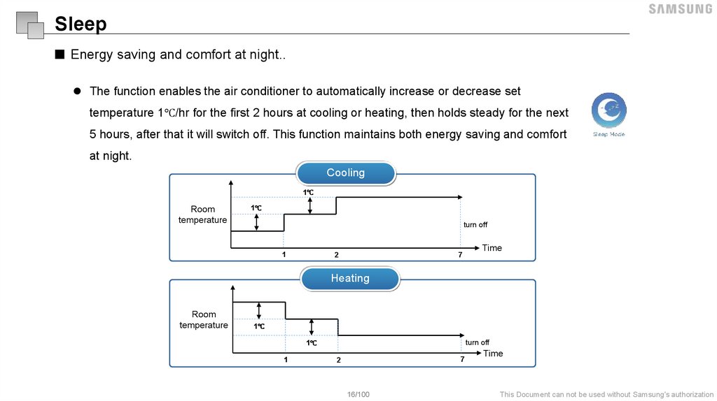
Sleep■ Energy saving and comfort at night..
The function enables the air conditioner to automatically increase or decrease set
temperature 1℃/hr for the first 2 hours at cooling or heating, then holds steady for the next
5 hours, after that it will switch off. This function maintains both energy saving and comfort
at night.
Cooling
1℃
Room
temperature
1℃
turn off
1
7
2
Time
Heating
Room
temperature
1℃
turn off
1℃
1
7
2
16/100
Time
This Document can not be used without Samsung's authorization
17.
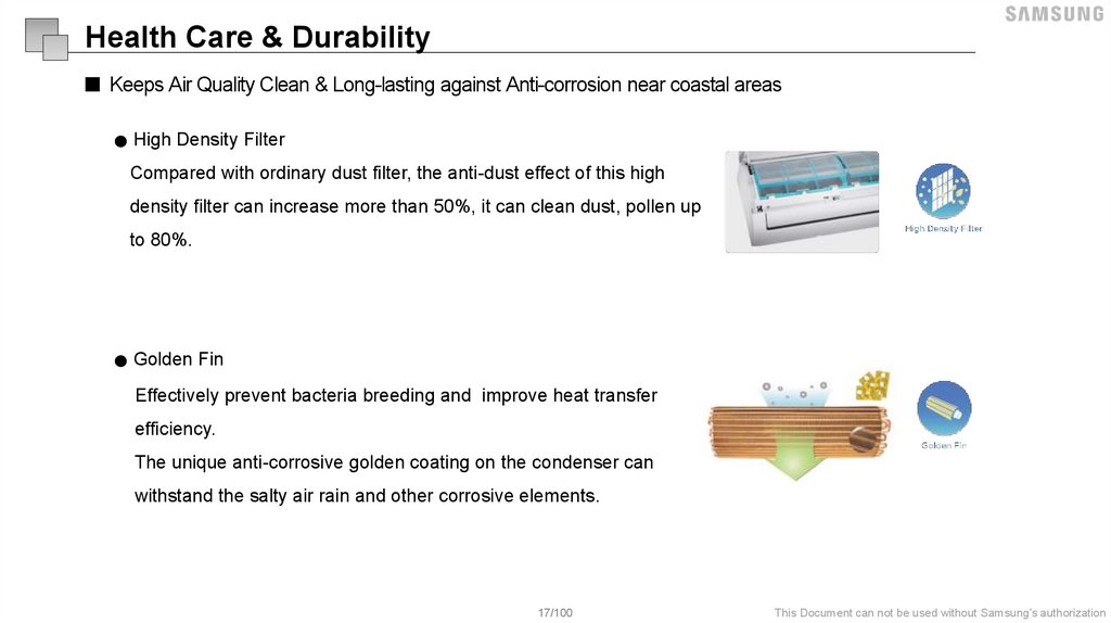
Health Care & Durability■ Keeps Air Quality Clean & Long-lasting against Anti-corrosion near coastal areas
● High Density Filter
Compared with ordinary dust filter, the anti-dust effect of this high
density filter can increase more than 50%, it can clean dust, pollen up
to 80%.
● Golden Fin
Effectively prevent bacteria breeding and improve heat transfer
efficiency.
The unique anti-corrosive golden coating on the condenser can
withstand the salty air rain and other corrosive elements.
17/100
This Document can not be used without Samsung's authorization
18.
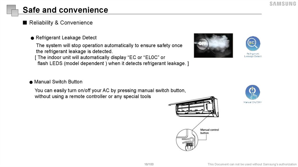
Safe and convenience■ Reliability & Convenience
● Refrigerant Leakage Detect
The system will stop operation automatically to ensure safety once
the refrigerant leakage is detected.
[ The indoor unit will automatically display “EC or “EL0C” or
flash LEDS (model dependent ) when it detects refrigerant leakage. ]
● Manual Switch Button
You can easily turn on/off your AC by pressing manual switch button,
without using a remote controller or any special tools
18/100
This Document can not be used without Samsung's authorization
19.
Installation guide20.
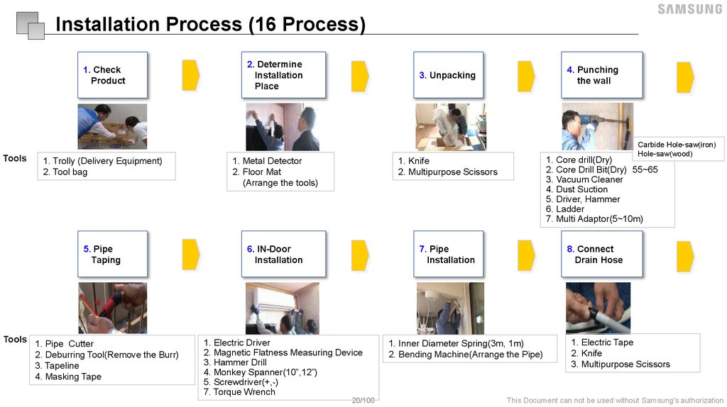
Installation Process (16 Process)1. Check
Product
Tools
2. Determine
Installation
Place
1. Trolly (Delivery Equipment)
2. Tool bag
1. Metal Detector
2. Floor Mat
(Arrange the tools)
1. Knife
2. Multipurpose Scissors
5. Pipe
Taping
6. IN-Door
Installation
7. Pipe
Installation
Tools 1. Pipe Cutter
2. Deburring Tool(Remove the Burr)
3. Tapeline
4. Masking Tape
4. Punching
the wall
3. Unpacking
1. Electric Driver
2. Magnetic Flatness Measuring Device
3. Hammer Drill
4. Monkey Spanner(10”,12”)
5. Screwdriver(+,-)
7. Torque Wrench
20/100
Carbide Hole-saw(iron)
Hole-saw(wood)
1. Core drill(Dry)
2. Core Drill Bit(Dry) 55~65
3. Vacuum Cleaner
4. Dust Suction
5. Driver, Hammer
6. Ladder
7. Multi Adaptor(5~10m)
8. Connect
Drain Hose
1. Inner Diameter Spring(3m, 1m)
2. Bending Machine(Arrange the Pipe)
1. Electric Tape
2. Knife
3. Multipurpose Scissors
This Document can not be used without Samsung's authorization
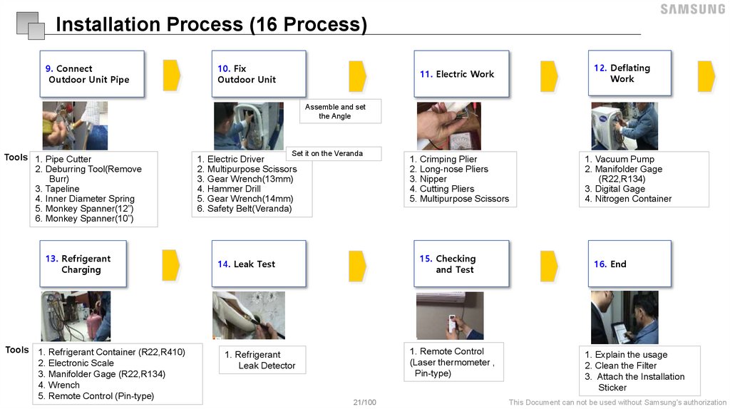
21.
Installation Process (16 Process)9. Connect
Outdoor Unit Pipe
10. Fix
Outdoor Unit
11. Electric Work
12. Deflating
Work
1. Crimping Plier
2. Long-nose Pliers
3. Nipper
4. Cutting Pliers
5. Multipurpose Scissors
1. Vacuum Pump
2. Manifolder Gage
(R22,R134)
3. Digital Gage
4. Nitrogen Container
Assemble and set
the Angle
Set it on the Veranda
Tools 1. Pipe Cutter
2. Deburring Tool(Remove
Burr)
3. Tapeline
4. Inner Diameter Spring
5. Monkey Spanner(12”)
6. Monkey Spanner(10”)
1. Electric Driver
2. Multipurpose Scissors
3. Gear Wrench(13mm)
4. Hammer Drill
5. Gear Wrench(14mm)
6. Safety Belt(Veranda)
13. Refrigerant
Charging
14. Leak Test
Tools
1. Refrigerant Container (R22,R410)
2. Electronic Scale
3. Manifolder Gage (R22,R134)
4. Wrench
5. Remote Control (Pin-type)
15. Checking
and Test
1. Remote Control
(Laser thermometer ,
Pin-type)
1. Refrigerant
Leak Detector
21/100
16. End
1. Explain the usage
2. Clean the Filter
3. Attach the Installation
Sticker
This Document can not be used without Samsung's authorization
22.
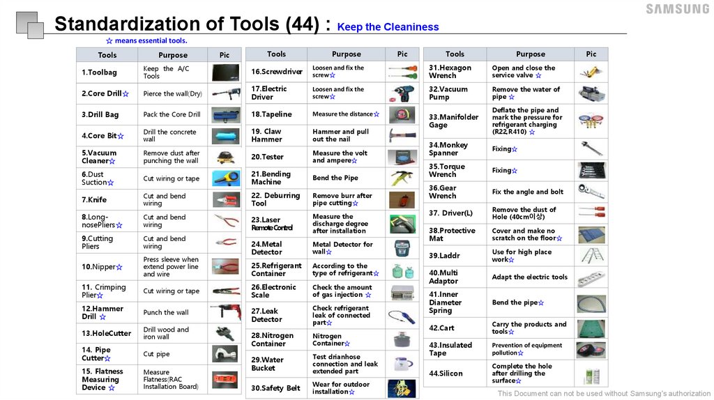
Standardization of Tools (44) : Keep the Cleaniness☆ means essential tools.
Pic
Tools
Purpose
Pic
Tools
Purpose
Tools
Purpose
1.Toolbag
Keep the A/C
Tools
16.Screwdriver
Loosen and fix the
screw☆
31.Hexagon
Wrench
Open and close the
service valve ☆
2.Core Drill☆
Pierce the wall(Dry)
17.Electric
Driver
Loosen and fix the
screw☆
32.Vacuum
Pump
Remove the water of
pipe ☆
3.Drill Bag
Pack the Core Drill
18.Tapeline
Measure the distance☆
4.Core Bit☆
Drill the concrete
wall
19. Claw
Hammer
Hammer and pull
out the nail
33.Manifolder
Gage
Deflate the pipe and
mark the pressure for
refrigerant charging
(R22,R410) ☆
5.Vacuum
Cleaner☆
Remove dust after
punching the wall
20.Tester
Measure the volt
and ampere☆
34.Monkey
Spanner
Fixing☆
6.Dust
Suction☆
Cut wiring or tape
21.Bending
Machine
Bend the Pipe
35.Torque
Wrench
Fixing☆
7.Knife
Cut and bend
wiring
22. Deburring
Tool
Remove burr after
pipe cutting☆
36.Gear
Wrench
Fix the angle and bolt
8.LongnosePliers☆
Cut and bend
wiring
23.Laser
RemoteControl
37. Driver(L)
Remove the dust of
Hole (40cm이상)
9.Cutting
Pliers
Cut and bend
wiring
Measure the
discharge degree
after installation
Metal Detector for
wall☆
Cover and make no
scratch on the floor☆
39.Laddr
10.Nipper☆
Press sleeve when
extend power line
and wire
24.Metal
Detector
38.Protective
Mat
25.Refrigerant
Container
According to the
type of refrigerant☆
Use for high place
work☆
Adapt the electric tools
Check the amount
of gas injection ☆
40.Multi
Adaptor
41.Inner
Diameter
Spring
Bend the pipe☆
42.Cart
Carry the products and
tools☆
43.Insulated
Tape
Prevention of equipment
pollution☆
44.Silicon
Complete the hole
after drilling the
surface☆
11. Crimping
Plier☆
Cut wiring or tape
26.Electronic
Scale
12.Hammer
Drill ☆
Punch the wall
27.Leak
Detector
13.HoleCutter
Drill wood and
iron wall
Check refrigerant
leak of connected
part☆
14. Pipe
Cutter☆
28.Nitrogen
Container
Nitrogen
Container☆
Cut pipe
15. Flatness
Measuring
Device ☆
Measure
Flatness(RAC
Installation Board)
29.Water
Bucket
Test drianhose
connection and leak
extended part
30.Safety Belt
Wear for outdoor
installation☆
22/100
Pic
This Document can not be used without Samsung's authorization
23.
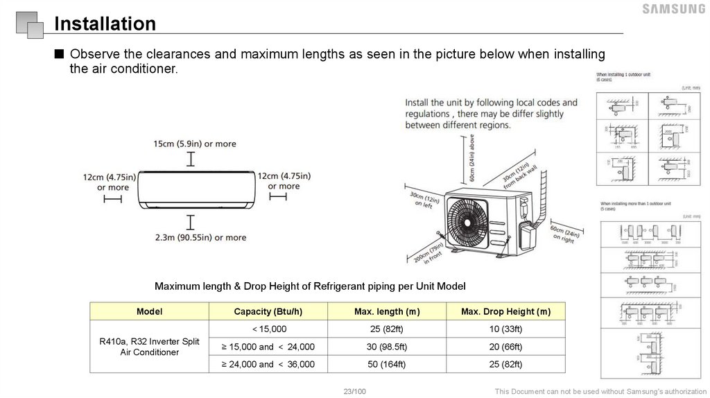
Installation■ Observe the clearances and maximum lengths as seen in the picture below when installing
the air conditioner.
Maximum length & Drop Height of Refrigerant piping per Unit Model
Model
R410a, R32 Inverter Split
Air Conditioner
Capacity (Btu/h)
Max. length (m)
Max. Drop Height (m)
15,000
25 (82ft)
10 (33ft)
≥ 15,000 and 24,000
30 (98.5ft)
20 (66ft)
≥ 24,000 and 36,000
50 (164ft)
25 (82ft)
23/100
This Document can not be used without Samsung's authorization
24.
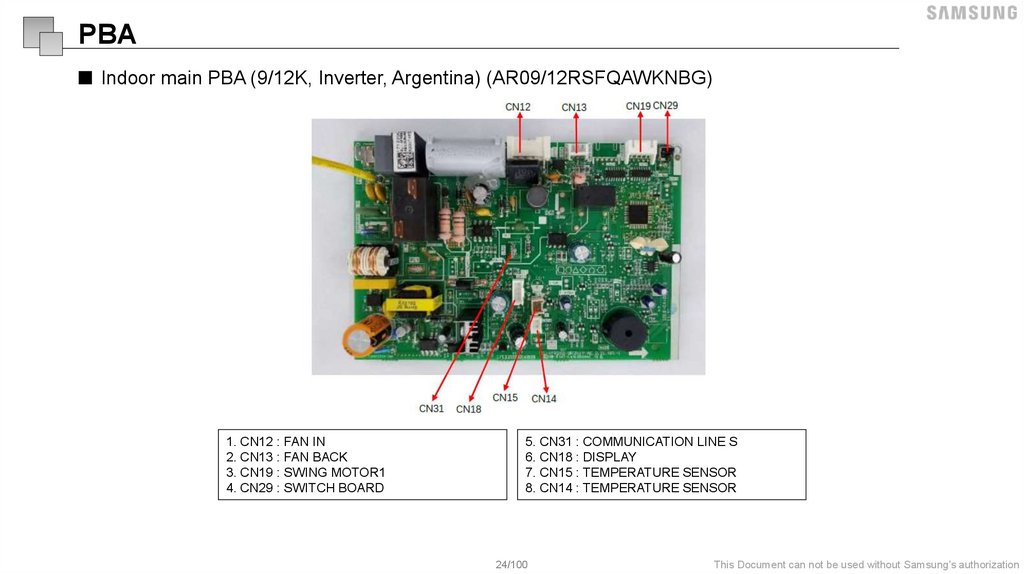
PBA■ Indoor main PBA (9/12K, Inverter, Argentina) (AR09/12RSFQAWKNBG)
1. CN12 : FAN IN
2. CN13 : FAN BACK
3. CN19 : SWING MOTOR1
4. CN29 : SWITCH BOARD
5. CN31 : COMMUNICATION LINE S
6. CN18 : DISPLAY
7. CN15 : TEMPERATURE SENSOR
8. CN14 : TEMPERATURE SENSOR
24/100
This Document can not be used without Samsung's authorization
25.
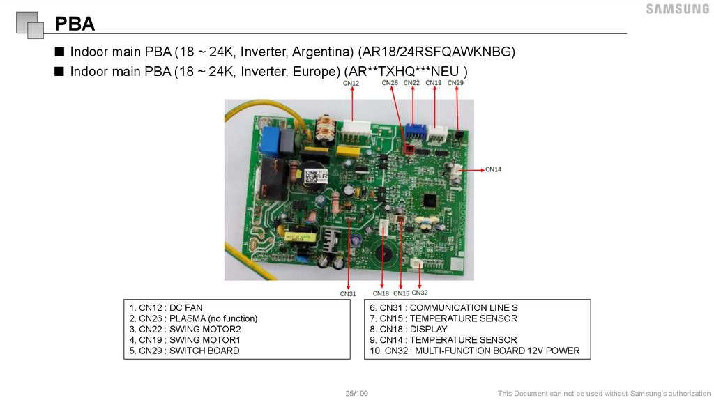
PBA■ Indoor main PBA (18 ~ 24K, Inverter, Argentina) (AR18/24RSFQAWKNBG)
■ Indoor main PBA (18 ~ 24K, Inverter, Europe) (AR**TXHQ***NEU )
1. CN12 : DC FAN
2. CN26 : PLASMA (no function)
3. CN22 : SWING MOTOR2
4. CN19 : SWING MOTOR1
5. CN29 : SWITCH BOARD
6. CN31 : COMMUNICATION LINE S
7. CN15 : TEMPERATURE SENSOR
8. CN18 : DISPLAY
9. CN14 : TEMPERATURE SENSOR
10. CN32 : MULTI-FUNCTION BOARD 12V POWER
25/100
This Document can not be used without Samsung's authorization
26.
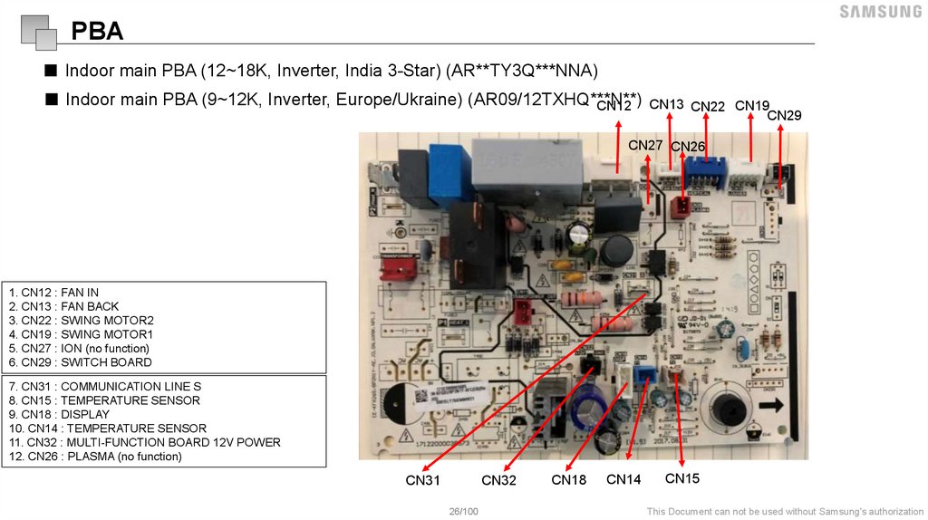
PBA■ Indoor main PBA (12~18K, Inverter, India 3-Star) (AR**TY3Q***NNA)
■ Indoor main PBA (9~12K, Inverter, Europe/Ukraine) (AR09/12TXHQ***N**)
CN12 CN13 CN22 CN19
CN29
CN27 CN26
1. CN12 : FAN IN
2. CN13 : FAN BACK
3. CN22 : SWING MOTOR2
4. CN19 : SWING MOTOR1
5. CN27 : ION (no function)
6. CN29 : SWITCH BOARD
7. CN31 : COMMUNICATION LINE S
8. CN15 : TEMPERATURE SENSOR
9. CN18 : DISPLAY
10. CN14 : TEMPERATURE SENSOR
11. CN32 : MULTI-FUNCTION BOARD 12V POWER
12. CN26 : PLASMA (no function)
7. CN31 : COMMUNICATION LINE S
8. CN15 : TEMPERATURE SENSOR
9. CN18 : DISPLAY
10. CN14 : TEMPERATURE SENSOR
11. CN32 : MULTI-FUNCTION BOARD 12V POWER
12. CN26 : PLASMA (no function)
CN31
CN32
26/100
CN18
CN14
CN15
This Document can not be used without Samsung's authorization
27.
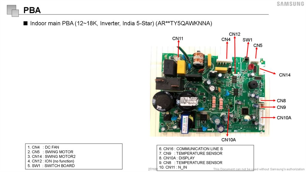
PBA■ Indoor main PBA (12~18K, Inverter, India 5-Star) (AR**TY5QAWKNNA)
CN11
CN12
CN4
SW1
CN5
CN14
CN8
CN9
CN10A
CN10A
1. CN4 : DC FAN
2. CN5 : SWING MOTOR
3. CN14 : SWING MOTOR2
4. CN12 : ION (no function)
5. SW1 : SWITCH BOARD
6. CN16 : COMMUNICATION LINE S
7. CN9 : TEMPERATURE SENSOR
8. CN10A : DISPLAY
9. CN8 : TEMPERATURE SENSOR
10. CN11 : N_IN
This Document can not be used without Samsung's authorization
27/100
28.
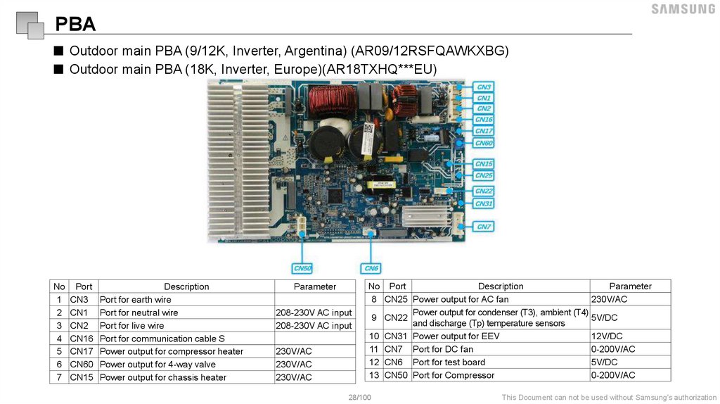
PBA■ Outdoor main PBA (9/12K, Inverter, Argentina) (AR09/12RSFQAWKXBG)
■ Outdoor main PBA (18K, Inverter, Europe)(AR18TXHQ***EU)
No Port
1 CN3
2 CN1
3 CN2
4 CN16
5 CN17
6 CN60
7 CN15
Description
Port for earth wire
Port for neutral wire
Port for live wire
Port for communication cable S
Power output for compressor heater
Power output for 4-way valve
Power output for chassis heater
Parameter
208-230V AC input
208-230V AC input
230V/AC
230V/AC
230V/AC
No Port
Description
Parameter
8 CN25 Power output for AC fan
230V/AC
Power output for condenser (T3), ambient (T4)
9 CN22
5V/DC
and discharge (Tp) temperature sensors
10 CN31 Power output for EEV
12V/DC
11 CN7 Port for DC fan
0-200V/AC
12 CN6 Port for test board
5V/DC
13 CN50 Port for Compressor
0-200V/AC
28/100
This Document can not be used without Samsung's authorization
29.
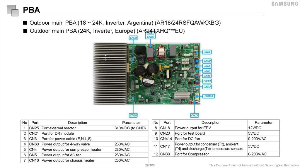
PBA■ Outdoor main PBA (18 ~ 24K, Inverter, Argentina) (AR18/24RSFQAWKXBG)
■ Outdoor main PBA (24K, Inverter, Europe) (AR24TXHQ***EU)
No Port
1 CN25
2 CN21
3 CN3
4 CN60
5 CN4
6 CN5
7 CN16
Description
Port external reactor
Port for DR module
Port for power cable (E,N,L,S)
Power output for 4-way valve
Power output for compressor heater
Power output for AC fan
Power output for chassis heater
Parameter
310V/DC (to GND)
230V/AC
230V/AC
230V/AC
230V/AC
No Port
Description
8 CN18 Power output for EEV
9 CN23 Port for test board
10 CN414 Port for DC fan
Power output for condenser (T3), ambient
11 CN17
(T4) and discharge (Tp) temperature sensors
12 CN30 Port for Compressor
29/100
Parameter
12V/DC
5V/DC
0-200V/AC
5V/DC
0-200V/AC
This Document can not be used without Samsung's authorization
30.
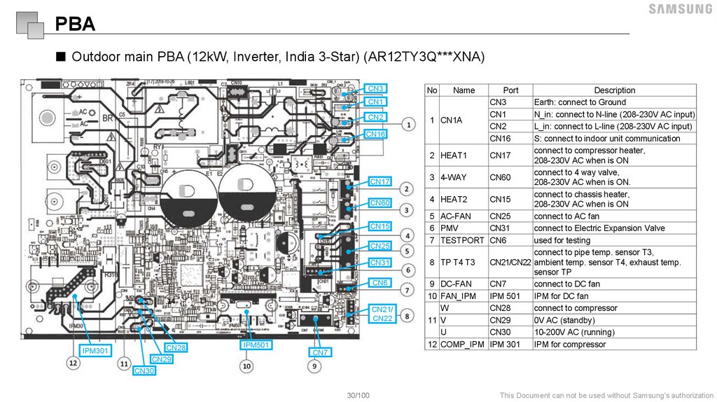
PBA■ Outdoor main PBA (12kW, Inverter, India 3-Star) (AR12TY3Q***XNA)
CN3
CN1
CN2
CN16
CN17
CN60
CN15
CN25
CN31
CN6
CN21/
CN22
CN28
IPM301
CN29
IPM501
No
Name
Port
CN3
CN1
CN2
CN16
Description
Earth: connect to Ground
N_in: connect to N-line (208-230V AC input)
1 CN1A
L_in: connect to L-line (208-230V AC input)
S: connect to indoor unit communication
connect to compressor heater,
2 HEAT1
CN17
208-230V AC when is ON
connect to 4 way valve,
3 4-WAY
CN60
208-230V AC when is ON.
connect to chassis heater,
4 HEAT2
CN15
208-230V AC when is ON
5 AC-FAN
CN25
connect to AC fan
6 PMV
CN31
connect to Electric Expansion Valve
7 TESTPORT CN6
used for testing
connect to pipe temp. sensor T3,
8 TP T4 T3
CN21/CN22 ambient temp. sensor T4, exhaust temp.
sensor TP
9 DC-FAN
CN7
connect to DC fan
10 FAN_IPM
IPM 501
IPM for DC fan
W
CN28
connect to compressor
11 V
CN29
0V AC (standby)
U
CN30
10-200V AC (running)
12 COMP_IPM IPM 301
IPM for compressor
CN7
CN30
30/100
This Document can not be used without Samsung's authorization
31.
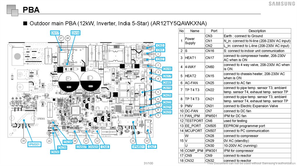
PBA■ Outdoor main PBA (12kW, Inverter, India 5-Star) (AR12TY5QAWKXNA)
No
CN3
CN1
2 S
Port
CN3
CN1
CN2
CN16
CN2
3 HEAT1
CN17
4 4-WAY
CN60
CN17
5 HEAT2
CN15
CN60
6 AC-FAN
CN25
7 TP T4 T3
CN22
8 TP T4 T3
CN21
CN18
CN17
1
CN16
CN15
Name
Power
Supply
CN25
CN22
CN21
CN31
IPM301
CN28
CN29
CN30
CN507 CN505
CN6
IPM501
CN7
31/100
9 PMV
CN31
10 DC-FAN
CN7
11 FAN_IPM
IPM501
12 TESTPORT CN6
13 EE_PORT CN505
14 MCUPORT CN507
W
CN28
15 V
CN29
U
CN30
16 COMP_IPM IPM301
17 CN9
CN9
18 CN32
CN32
Description
Earth : connect to Ground
N_in: connect to N-line (208-230V AC input)
L_in: connect to L-line (208-230V AC input)
S: connect to indoor unit communication
connect to compressor heater, 208-230V
AC when is ON
connect to 4 way valve, 208-230V AC when
is ON.
connect to chassis heater, 208-230V AC
when is ON
connect to AC fan
connect to pipe temp. sensor T3, ambient
temp. sensor T4, exhaust temp. sensor TP
connect to pipe temp. sensor T3, ambient
temp. sensor T4, exhaust temp. sensor TP
connect to Electric Expansion Valve
connect to DC fan
IPM for DC fan
used for testing
EEPROM programmer port
connect to PC communication
connect to compressor
0V AC (standby)
10-200V AC (running)
IPM for compressor
connect to reactor
connect to reactor
This Document can not be used without Samsung's authorization
32.
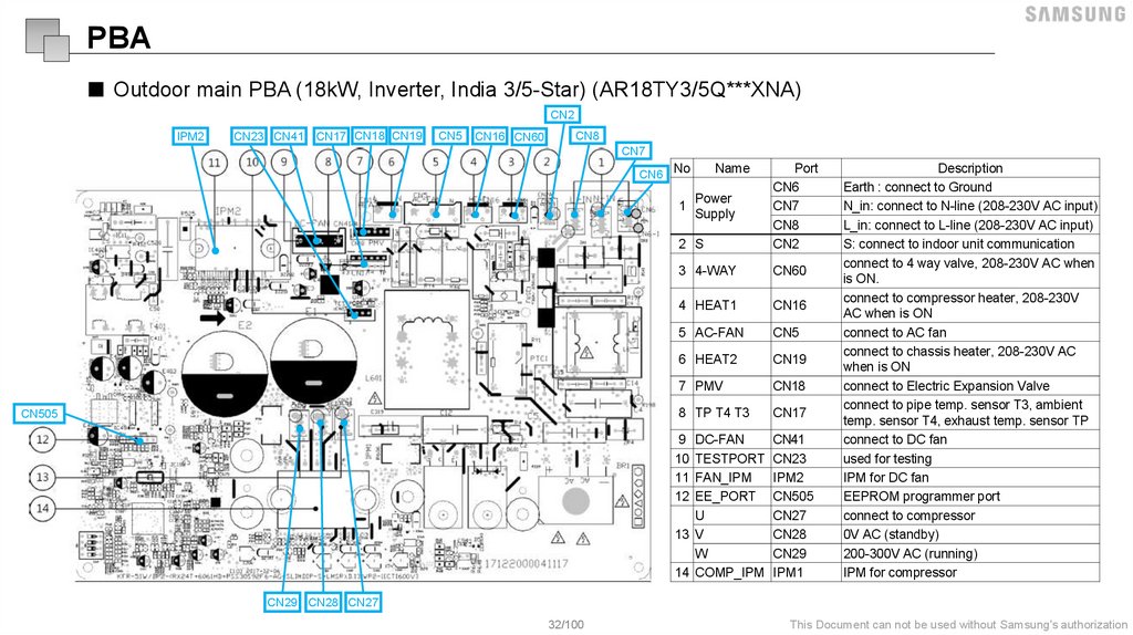
PBA■ Outdoor main PBA (18kW, Inverter, India 3/5-Star) (AR18TY3/5Q***XNA)
CN2
IPM2
CN23 CN41
CN17 CN18 CN19
CN5
CN16 CN60
CN8
CN7
CN6 No
2 S
Port
CN6
CN7
CN8
CN2
3 4-WAY
CN60
4 HEAT1
CN16
5 AC-FAN
CN5
6 HEAT2
CN19
7 PMV
CN18
8 TP T4 T3
CN17
1
CN505
Name
Power
Supply
9 DC-FAN
CN41
10 TESTPORT CN23
11 FAN_IPM
IPM2
12 EE_PORT CN505
U
CN27
13 V
CN28
W
CN29
14 COMP_IPM IPM1
Description
Earth : connect to Ground
N_in: connect to N-line (208-230V AC input)
L_in: connect to L-line (208-230V AC input)
S: connect to indoor unit communication
connect to 4 way valve, 208-230V AC when
is ON.
connect to compressor heater, 208-230V
AC when is ON
connect to AC fan
connect to chassis heater, 208-230V AC
when is ON
connect to Electric Expansion Valve
connect to pipe temp. sensor T3, ambient
temp. sensor T4, exhaust temp. sensor TP
connect to DC fan
used for testing
IPM for DC fan
EEPROM programmer port
connect to compressor
0V AC (standby)
200-300V AC (running)
IPM for compressor
CN29 CN28 CN27
32/100
This Document can not be used without Samsung's authorization
33.
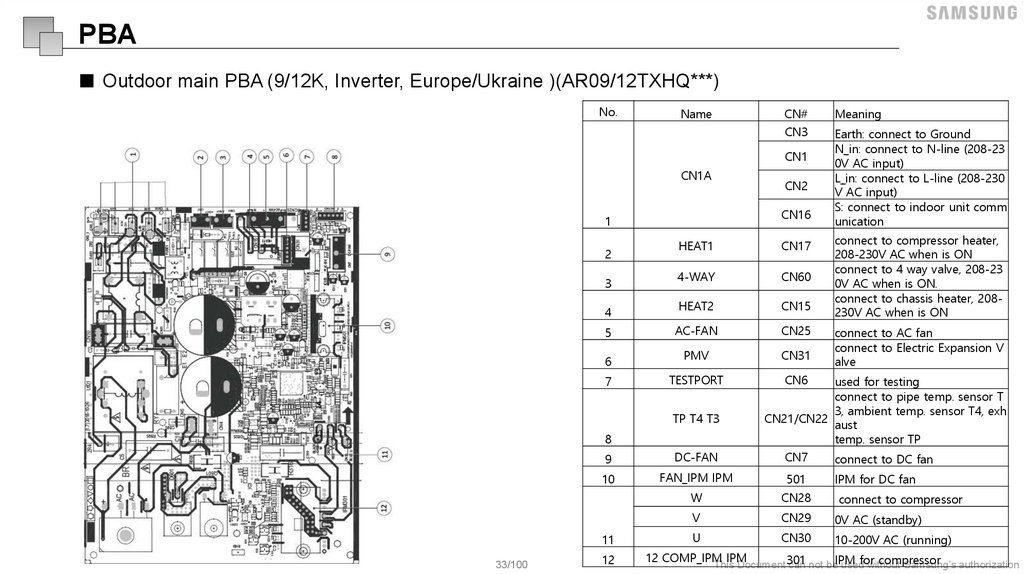
PBA■ Outdoor main PBA (9/12K, Inverter, Europe/Ukraine )(AR09/12TXHQ***)
No.
Name
CN#
Meaning
CN3
Earth: connect to Ground
N_in: connect to N-line (208-23
0V AC input)
L_in: connect to L-line (208-230
V AC input)
S: connect to indoor unit comm
unication
CN1
CN1A
CN16
1
2
3
4
5
6
7
HEAT1
CN17
4-WAY
CN60
HEAT2
CN15
AC-FAN
CN25
PMV
CN31
TESTPORT
CN6
TP T4 T3
8
connect to compressor heater,
208-230V AC when is ON
connect to 4 way valve, 208-23
0V AC when is ON.
connect to chassis heater, 208230V AC when is ON
connect to AC fan
connect to Electric Expansion V
alve
used for testing
connect to pipe temp. sensor T
3, ambient temp. sensor T4, exh
CN21/CN22
aust
temp. sensor TP
9
DC-FAN
CN7
connect to DC fan
10
FAN_IPM IPM
501
IPM for DC fan
W
CN28
connect to compressor
V
CN29
0V AC (standby)
U
CN30
10-200V AC (running)
11
33/100
CN2
12
12 COMP_IPM
IPM
compressor
This Document 301
can not beIPM
usedfor
without
Samsung's authorization
34.
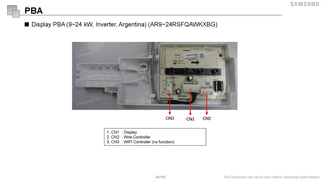
PBA■ Display PBA (9~24 kW, Inverter, Argentina) (AR9~24RSFQAWKXBG)
1. CN1 : Display
2. CN2 : Wire Controller
3. CN3 : WIFI Controller (no function)
34/100
This Document can not be used without Samsung's authorization
35.
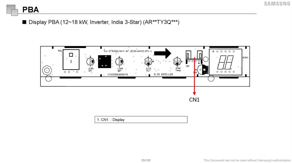
PBA■ Display PBA (12~18 kW, Inverter, India 3-Star) (AR**TY3Q***)
1. CN1 : Display
35/100
This Document can not be used without Samsung's authorization
36.
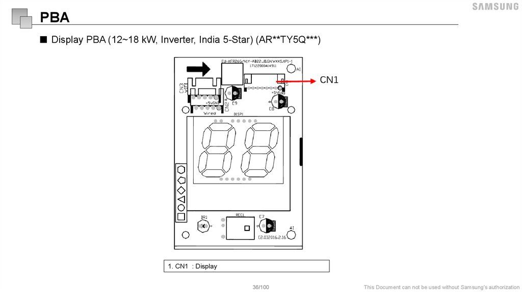
PBA■ Display PBA (12~18 kW, Inverter, India 5-Star) (AR**TY5Q***)
1. CN1 : Display
36/100
This Document can not be used without Samsung's authorization
37.
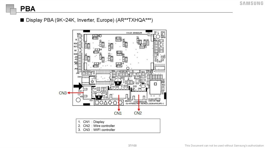
PBA■ Display PBA (9K~24K, Inverter, Europe) (AR**TXHQA***)
1. CN1 : Display
2. CN2 : Wire controller
3. CN3 : WIFI controller
37/100
This Document can not be used without Samsung's authorization
38.
Option code39.
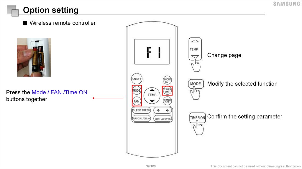
Option setting■ Wireless remote controller
Change page
Modify the selected function
Press the Mode / FAN /Time ON
buttons together
Confirm the setting parameter
39/100
This Document can not be used without Samsung's authorization
40.
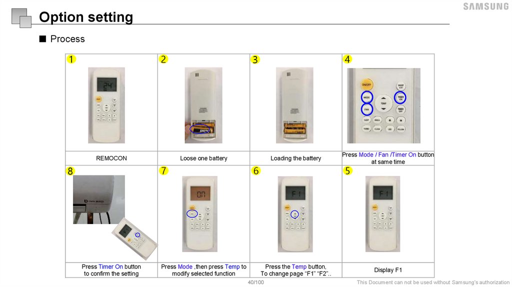
Option setting■ Process
2
1
REMOCON
Loose one battery
7
8
4
3
Loading the battery
6
Press Mode / Fan /Timer On button
at same time
5
-
Press Timer On button
to confirm the setting
Press Mode ,then press Temp to
modify selected function
Press the Temp button,
To change page “F1” “F2”..
40/100
Display F1
This Document can not be used without Samsung's authorization
41.
Option setting■ Process
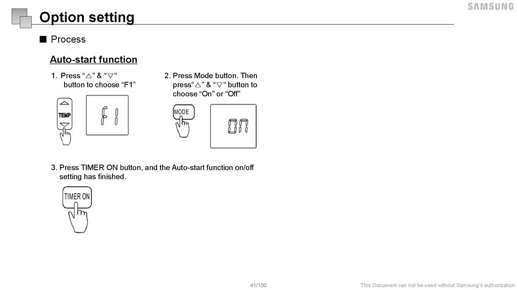
Auto-start function
1. Press “△” & “▽“
button to choose “F1”
2. Press Mode button. Then
press“△” & “▽“ button to
choose “On” or “Off”
3. Press TIMER ON button, and the Auto-start function on/off
setting has finished.
41/100
This Document can not be used without Samsung's authorization
42.
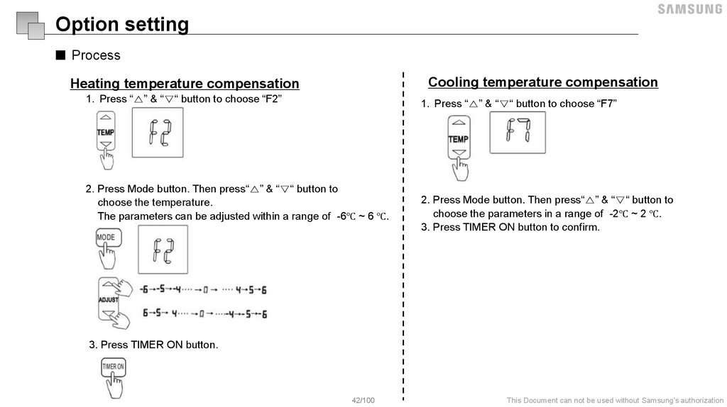
Option setting■ Process
Cooling temperature compensation
Heating temperature compensation
1. Press “△” & “▽“ button to choose “F2”
1. Press “△” & “▽“ button to choose “F7”
2. Press Mode button. Then press“△” & “▽“ button to
choose the temperature.
The parameters can be adjusted within a range of -6℃ ~ 6 ℃.
2. Press Mode button. Then press“△” & “▽“ button to
choose the parameters in a range of -2℃ ~ 2 ℃.
3. Press TIMER ON button to confirm.
3. Press TIMER ON button.
42/100
This Document can not be used without Samsung's authorization
43.
Option setting■ Process
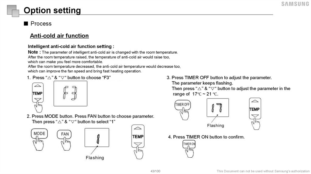
Anti-cold air function
Intelligent anti-cold air function setting :
Note : The parameter of intelligent anti-cold air is changed with the room temperature.
After the room temperature raised, the temperature of anti-cold air would raise too,
which can make you feel more comfortable.
After the room temperature decreased, the anti-cold air temperature would decrease too,
which can improve the fan speed and bring fast heating operation.
1. Press “△” & “▽“ button to choose “F3”
3. Press TIMER OFF button to adjust the parameter.
The parameter keeps flashing.
Then press “△” & “▽“ button to adjust the parameter in the
range of 17℃ ~ 21 ℃.
2. Press MODE button. Press FAN button to choose parameter.
Then press “△” & “▽“ button to select “1”
4. Press TIMER ON button to confirm.
43/100
This Document can not be used without Samsung's authorization
44.
Option setting■ Process
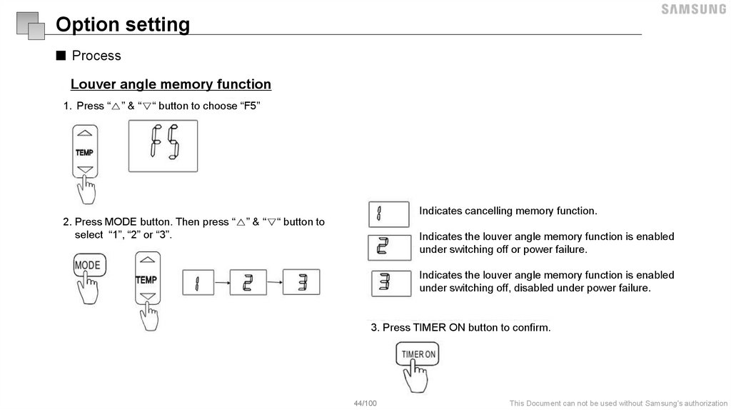
Louver angle memory function
1. Press “△” & “▽“ button to choose “F5”
Indicates cancelling memory function.
2. Press MODE button. Then press “△” & “▽“ button to
select “1”, “2” or “3”.
Indicates the louver angle memory function is enabled
under switching off or power failure.
Indicates the louver angle memory function is enabled
under switching off, disabled under power failure.
3. Press TIMER ON button to confirm.
44/100
This Document can not be used without Samsung's authorization
45.
Option setting■ Process
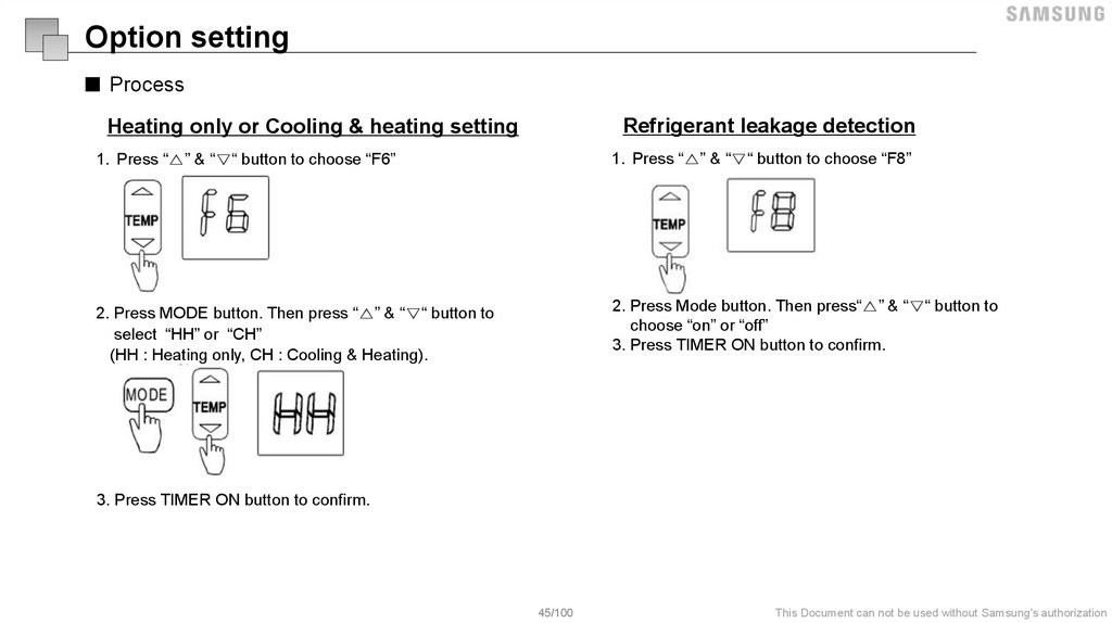
Heating only or Cooling & heating setting
Refrigerant leakage detection
1. Press “△” & “▽“ button to choose “F6”
1. Press “△” & “▽“ button to choose “F8”
2. Press MODE button. Then press “△” & “▽“ button to
select “HH” or “CH”
(HH : Heating only, CH : Cooling & Heating).
2. Press Mode button. Then press“△” & “▽“ button to
choose “on” or “off”
3. Press TIMER ON button to confirm.
3. Press TIMER ON button to confirm.
45/100
This Document can not be used without Samsung's authorization
46.
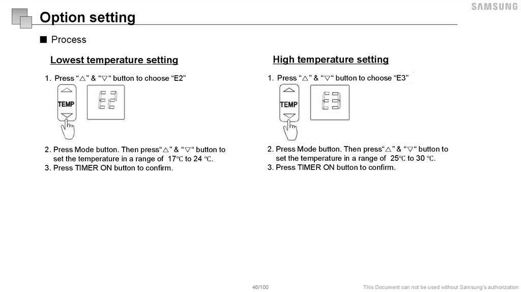
Option setting■ Process
High temperature setting
Lowest temperature setting
1. Press “△” & “▽“ button to choose “E2”
1. Press “△” & “▽“ button to choose “E3”
2. Press Mode button. Then press“△” & “▽“ button to
set the temperature in a range of 17℃ to 24 ℃.
3. Press TIMER ON button to confirm.
2. Press Mode button. Then press“△” & “▽“ button to
set the temperature in a range of 25℃ to 30 ℃.
3. Press TIMER ON button to confirm.
46/100
This Document can not be used without Samsung's authorization
47.
Trial Operation48.
Trial operation■ Process
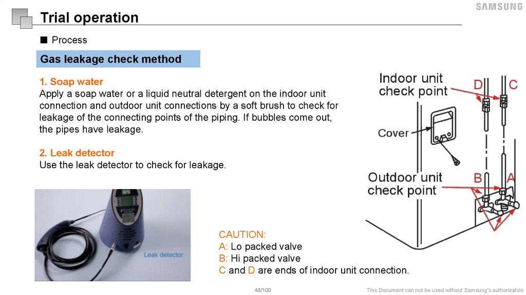
Gas leakage check method
1. Soap water
Apply a soap water or a liquid neutral detergent on the indoor unit
connection and outdoor unit connections by a soft brush to check for
leakage of the connecting points of the piping. If bubbles come out,
the pipes have leakage.
2. Leak detector
Use the leak detector to check for leakage.
CAUTION:
A: Lo packed valve
B: Hi packed valve
C and D are ends of indoor unit connection.
48/100
This Document can not be used without Samsung's authorization
49.
Trial operation■ Process
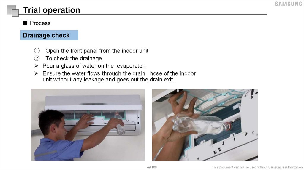
Drainage check
① Open the front panel from the indoor unit.
② To check the drainage.
Pour a glass of water on the evaporator.
Ensure the water flows through the drain hose of the indoor
unit without any leakage and goes out the drain exit.
49/100
This Document can not be used without Samsung's authorization
50.
Trial operation■ Process
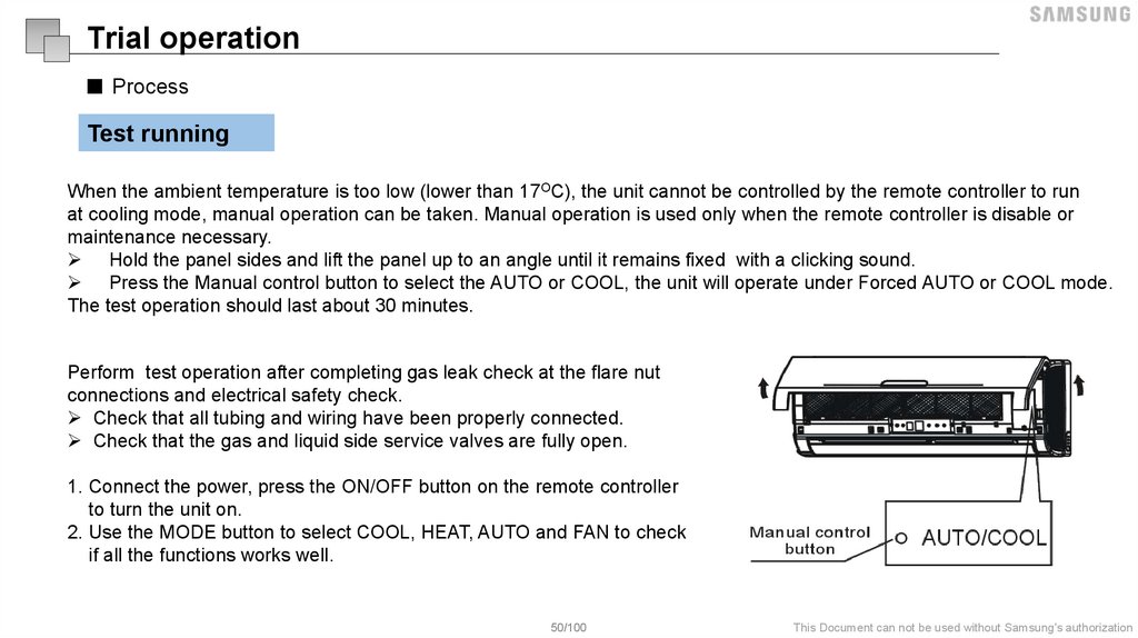
Test running
When the ambient temperature is too low (lower than 17OC), the unit cannot be controlled by the remote controller to run
at cooling mode, manual operation can be taken. Manual operation is used only when the remote controller is disable or
maintenance necessary.
Hold the panel sides and lift the panel up to an angle until it remains fixed with a clicking sound.
Press the Manual control button to select the AUTO or COOL, the unit will operate under Forced AUTO or COOL mode.
The test operation should last about 30 minutes.
Perform test operation after completing gas leak check at the flare nut
connections and electrical safety check.
Check that all tubing and wiring have been properly connected.
Check that the gas and liquid side service valves are fully open.
1. Connect the power, press the ON/OFF button on the remote controller
to turn the unit on.
2. Use the MODE button to select COOL, HEAT, AUTO and FAN to check
if all the functions works well.
50/100
This Document can not be used without Samsung's authorization
51.
Error code52.
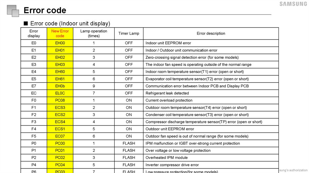
Error code■ Error code (Indoor unit display)
Error
display
New Error
code
Lamp operation
(times)
Timer Lamp
E0
EH00
1
OFF
Indoor unit EEPROM error
E1
EH01
2
OFF
Indoor / Outdoor unit communication error
E2
EH02
3
OFF
Zero-crossing signal detection error (for some models)
E3
EH03
4
OFF
The indoor fan speed is operating outside of the normal range
E4
EH60
5
OFF
Indoor room temperature sensor(T1) error (open or short)
E5
EH61
6
OFF
Evaporator coil temperature sensor(T2) error (open or short)
E7
EH0b
9
OFF
Communication error between Indoor PCB and Display PCB
EC
EL0C
7
OFF
Refrigerant leak detected
F0
PC08
1
ON
Current overload protection
F1
ECS3
2
ON
Outdoor room temperature sensor(T4) error (open or short)
F2
ECS2
3
ON
Condenser coil temperature sensor(T3) error (open or short)
F3
ECS4
4
ON
Compressor discharge temperature sensor(TP) error (open or short)
F4
ECS1
5
ON
Outdoor unit EEPROM error
F5
EC07
6
ON
Outdoor fan speed is out of normal range (for some models)
P0
PC00
1
FLASH
IPM malfunction or IGBT over-strong current protection
P1
PC01
2
FLASH
Over voltage or low voltage protection
P2
PC02
3
FLASH
Overheated IPM module
P4
PC04
5
FLASH
Inverter compressor drive error
P6
PC03
7
FLASH
Low pressure protection(for some models)
Error description
52/100
This Document can not be used without Samsung's authorization
53.
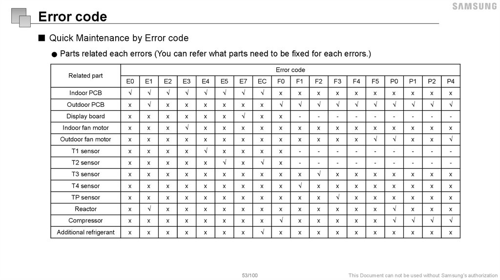
Error code■ Quick Maintenance by Error code
● Parts related each errors (You can refer what parts need to be fixed for each errors.)
Error code
Related part
E0
E1
E2
E3
E4
E5
E7
EC
F0
F1
F2
F3
F4
F5
P0
P1
P2
P4
Indoor PCB
√
√
√
√
√
√
√
√
x
x
x
x
x
x
x
x
x
x
Outdoor PCB
x
√
x
x
x
x
x
x
√
√
√
√
√
√
√
√
√
√
Display board
x
x
x
x
x
x
√
x
x
-
-
-
-
-
-
-
-
-
Indoor fan motor
x
x
x
√
x
x
x
x
x
x
x
x
x
x
x
x
x
x
Outdoor fan motor
x
x
x
x
x
x
x
x
x
x
x
x
x
√
√
x
x
√
T1 sensor
x
x
x
x
√
x
x
x
x
-
-
-
-
-
-
-
-
-
T2 sensor
x
x
x
x
x
√
x
√
x
-
-
-
-
-
-
-
-
-
T3 sensor
x
x
x
x
x
x
x
x
x
x
√
x
x
x
x
x
x
x
T4 sensor
x
x
x
x
x
x
x
x
x
√
x
x
x
x
x
x
x
x
TP sensor
x
x
x
x
x
x
x
x
x
x
x
√
x
x
x
x
x
x
Reactor
x
√
x
x
x
x
x
x
x
x
x
x
x
x
√
x
x
x
Compressor
x
x
x
x
x
x
x
x
√
x
x
x
x
x
√
√
√
√
Additional refrigerant
x
x
x
x
x
x
x
√
x
x
x
x
x
x
x
x
x
x
53/100
This Document can not be used without Samsung's authorization
54.
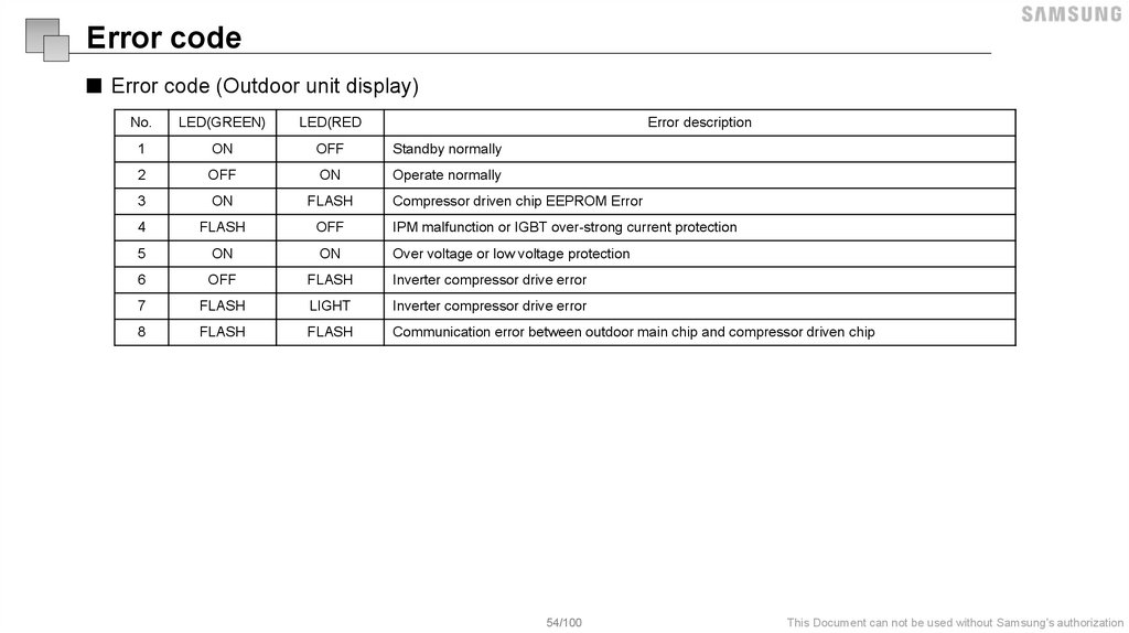
Error code■ Error code (Outdoor unit display)
No.
LED(GREEN)
LED(RED
Error description
1
ON
OFF
Standby normally
2
OFF
ON
Operate normally
3
ON
FLASH
Compressor driven chip EEPROM Error
4
FLASH
OFF
IPM malfunction or IGBT over-strong current protection
5
ON
ON
Over voltage or low voltage protection
6
OFF
FLASH
Inverter compressor drive error
7
FLASH
LIGHT
Inverter compressor drive error
8
FLASH
FLASH
Communication error between outdoor main chip and compressor driven chip
54/100
This Document can not be used without Samsung's authorization
55.
Refrigerant circuit56.
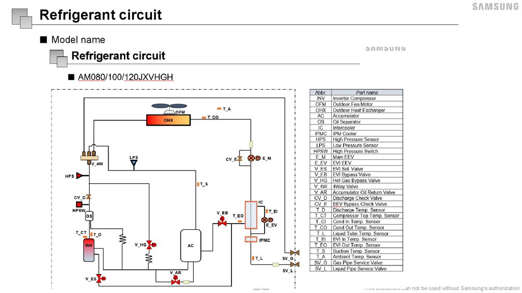
Refrigerant circuit■ Model name
56/100
This Document can not be used without Samsung's authorization
57.
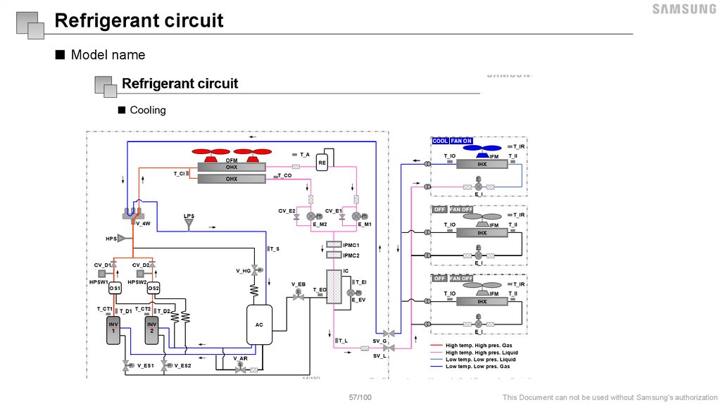
Refrigerant circuit■ Model name
57/100
This Document can not be used without Samsung's authorization
58.
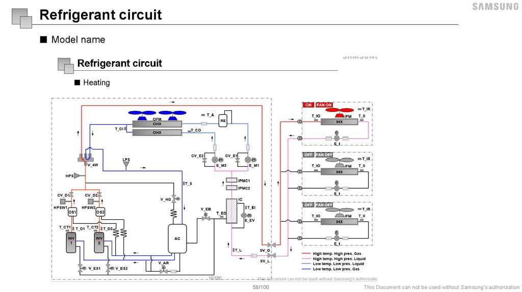
Refrigerant circuit■ Model name
58/100
This Document can not be used without Samsung's authorization
59.
Troubleshooting60.
InverterTroubleshooting
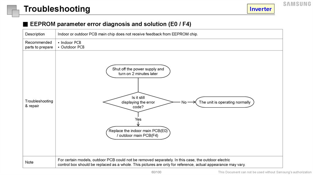
■ EEPROM parameter error diagnosis and solution (E0 / F4)
Description
Indoor or outdoor PCB main chip does not receive feedback from EEPROM chip.
Recommended
parts to prepare
• Indoor PCB
• Outdoor PCB
Shut off the power supply and
turn on 2 minutes later
Troubleshooting
& repair
Is it still
displaying the error
code?
No
The unit is operating normally
Yes
Replace the indoor main PCB(E0)
/ outdoor main PCB(F4)
Note
For certain models, outdoor PCB could not be removed separately. In this case, the outdoor electric
control box should be replaced as a whole. This pictures are only for reference, actual appearance may vary.
60/100
This Document can not be used without Samsung's authorization
61.
InverterTroubleshooting
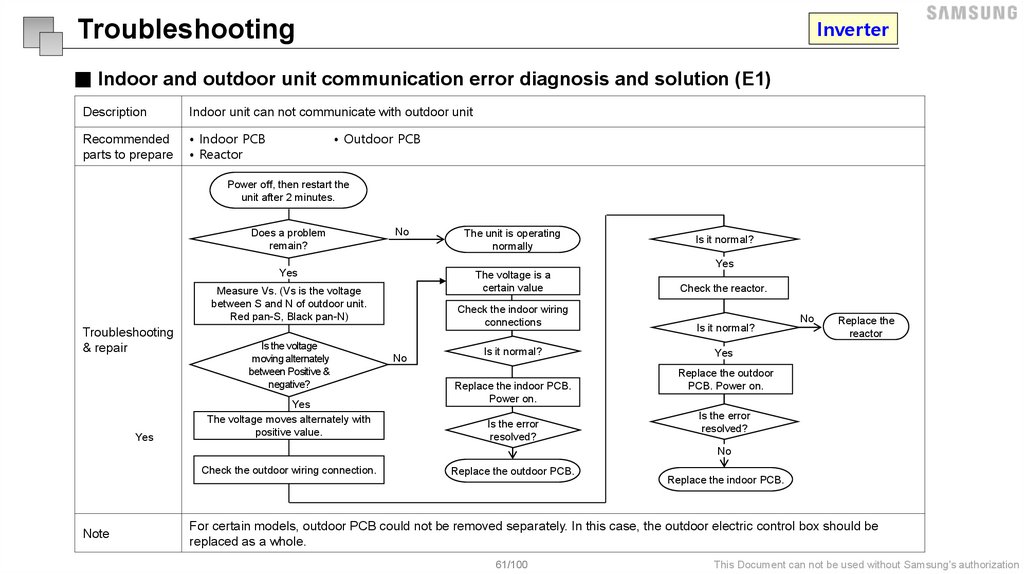
■ Indoor and outdoor unit communication error diagnosis and solution (E1)
Description
Indoor unit can not communicate with outdoor unit
Recommended
parts to prepare
• Indoor PCB
• Reactor
• Outdoor PCB
Power off, then restart the
unit after 2 minutes.
Does a problem
remain?
No
The voltage is a
certain value
Measure Vs. (Vs is the voltage
between S and N of outdoor unit.
Red pan-S, Black pan-N)
Yes
Is the voltage
moving alternately
between Positive &
negative?
Yes
The voltage moves alternately with
positive value.
Is it normal?
Yes
Yes
Troubleshooting
& repair
The unit is operating
normally
Check the indoor wiring
connections
No
Is it normal?
Replace the indoor PCB.
Power on.
Is the error
resolved?
Check the reactor.
Is it normal?
No
Replace the
reactor
Yes
Replace the outdoor
PCB. Power on.
Is the error
resolved?
No
Check the outdoor wiring connection.
Note
Replace the outdoor PCB.
Replace the indoor PCB.
For certain models, outdoor PCB could not be removed separately. In this case, the outdoor electric control box should be
replaced as a whole.
61/100
This Document can not be used without Samsung's authorization
62.
InverterTroubleshooting
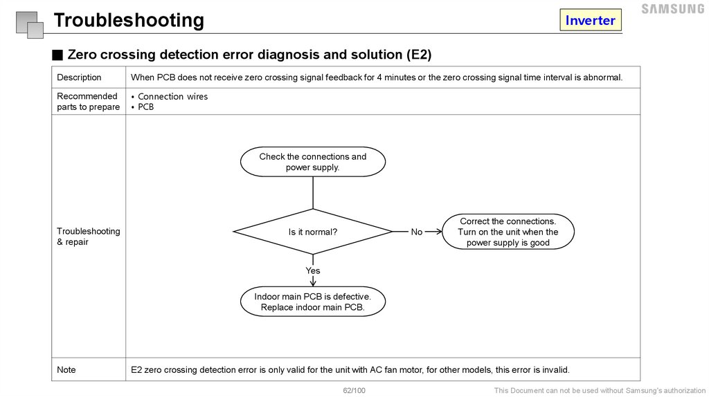
■ Zero crossing detection error diagnosis and solution (E2)
Description
When PCB does not receive zero crossing signal feedback for 4 minutes or the zero crossing signal time interval is abnormal.
Recommended
parts to prepare
• Connection wires
• PCB
Check the connections and
power supply.
Troubleshooting
& repair
No
Is it normal?
Correct the connections.
Turn on the unit when the
power supply is good
Yes
Indoor main PCB is defective.
Replace indoor main PCB.
Note
E2 zero crossing detection error is only valid for the unit with AC fan motor, for other models, this error is invalid.
62/100
This Document can not be used without Samsung's authorization
63.
InverterTroubleshooting
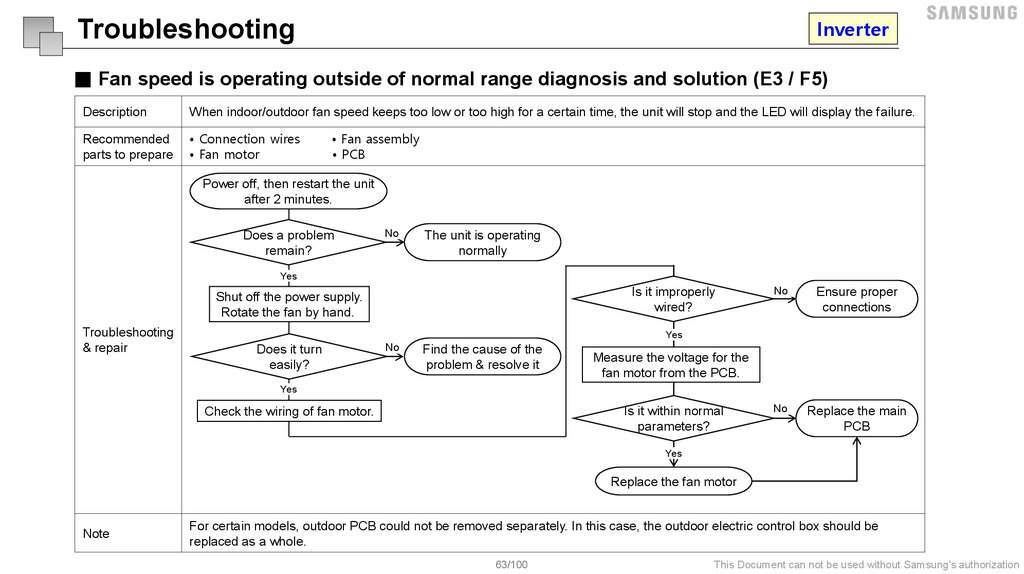
■ Fan speed is operating outside of normal range diagnosis and solution (E3 / F5)
Description
When indoor/outdoor fan speed keeps too low or too high for a certain time, the unit will stop and the LED will display the failure.
Recommended
parts to prepare
• Connection wires
• Fan motor
• Fan assembly
• PCB
Power off, then restart the unit
after 2 minutes.
Does a problem
remain?
No
The unit is operating
normally
Yes
Is it improperly
wired?
Shut off the power supply.
Rotate the fan by hand.
Troubleshooting
& repair
No
Ensure proper
connections
No
Replace the main
PCB
Yes
Does it turn
easily?
No
Find the cause of the
problem & resolve it
Measure the voltage for the
fan motor from the PCB.
Yes
Is it within normal
parameters?
Check the wiring of fan motor.
Yes
Replace the fan motor
Note
For certain models, outdoor PCB could not be removed separately. In this case, the outdoor electric control box should be
replaced as a whole.
63/100
This Document can not be used without Samsung's authorization
64.
InverterTroubleshooting
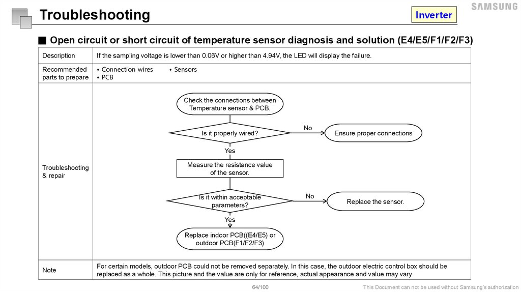
■ Open circuit or short circuit of temperature sensor diagnosis and solution (E4/E5/F1/F2/F3)
Description
If the sampling voltage is lower than 0.06V or higher than 4.94V, the LED will display the failure.
Recommended
parts to prepare
• Connection wires
• PCB
• Sensors
Check the connections between
Temperature sensor & PCB.
Is it properly wired?
No
Ensure proper connections
Yes
Troubleshooting
& repair
Measure the resistance value
of the sensor.
Is it within acceptable
parameters?
No
Replace the sensor.
Yes
Replace indoor PCB((E4/E5) or
outdoor PCB(F1/F2/F3)
Note
For certain models, outdoor PCB could not be removed separately. In this case, the outdoor electric control box should be
replaced as a whole. This picture and the value are only for reference, actual appearance and value may vary
64/100
This Document can not be used without Samsung's authorization
65.
InverterTroubleshooting
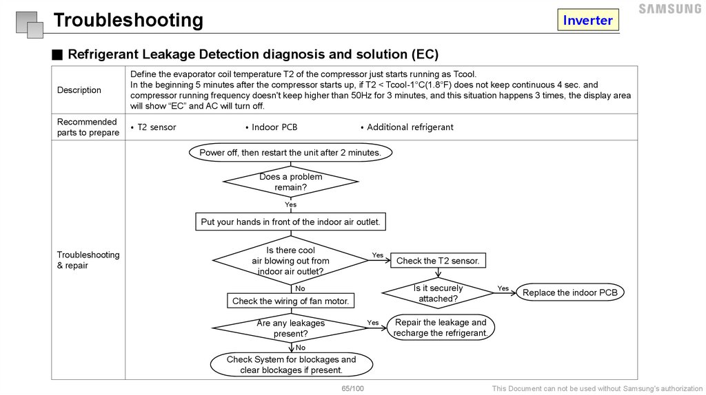
■ Refrigerant Leakage Detection diagnosis and solution (EC)
Description
Define the evaporator coil temperature T2 of the compressor just starts running as Tcool.
In the beginning 5 minutes after the compressor starts up, if T2 < Tcool-1°C(1.8°F) does not keep continuous 4 sec. and
compressor running frequency doesn't keep higher than 50Hz for 3 minutes, and this situation happens 3 times, the display area
will show “EC” and AC will turn off.
Recommended
parts to prepare
• T2 sensor
• Indoor PCB
• Additional refrigerant
Power off, then restart the unit after 2 minutes.
Does a problem
remain?
Yes
Put your hands in front of the indoor air outlet.
Troubleshooting
& repair
Is there cool
air blowing out from
indoor air outlet?
Yes
Is it securely
attached?
No
Check the wiring of fan motor.
Are any leakages
present?
Check the T2 sensor.
Yes
Yes
Replace the indoor PCB
Repair the leakage and
recharge the refrigerant.
No
Check System for blockages and
clear blockages if present.
65/100
This Document can not be used without Samsung's authorization
66.
InverterTroubleshooting
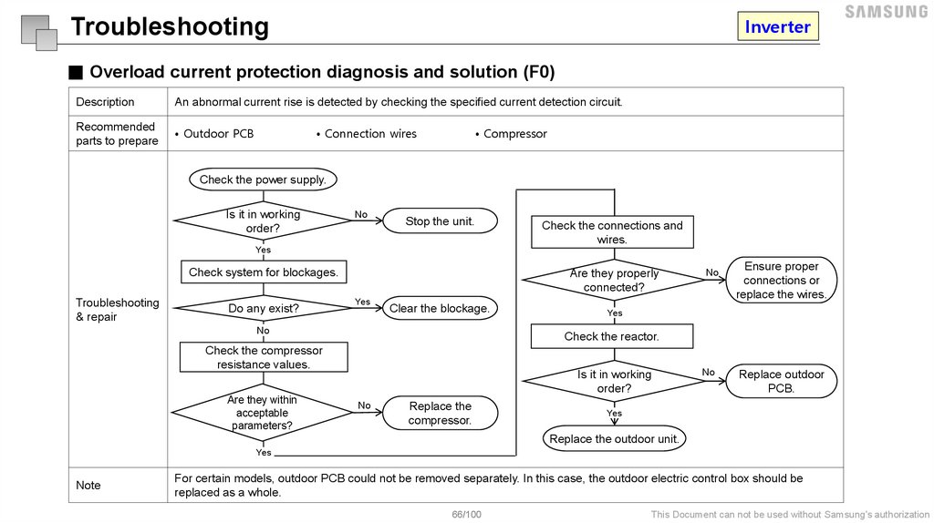
■ Overload current protection diagnosis and solution (F0)
Description
An abnormal current rise is detected by checking the specified current detection circuit.
Recommended
parts to prepare
• Outdoor PCB
• Connection wires
• Compressor
Check the power supply.
Is it in working
order?
No
Stop the unit.
Check the connections and
wires.
Yes
Check system for blockages.
Troubleshooting
& repair
Do any exist?
Are they properly
connected?
Yes
Clear the blockage.
No
Ensure proper
connections or
replace the wires.
Yes
Check the reactor.
Check the compressor
resistance values.
Are they within
acceptable
parameters?
No
Is it in working
order?
No
Replace the
compressor.
No
Replace outdoor
PCB.
Yes
Replace the outdoor unit.
Yes
Note
For certain models, outdoor PCB could not be removed separately. In this case, the outdoor electric control box should be
replaced as a whole.
66/100
This Document can not be used without Samsung's authorization
67.
InverterTroubleshooting
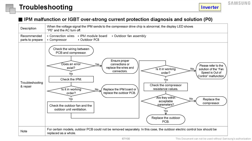
■ IPM malfunction or IGBT over-strong current protection diagnosis and solution (P0)
Description
When the voltage signal the IPM sends to the compressor drive chip is abnormal, the display LED shows
“P0” and the AC turn off.
Recommended
parts to prepare
• Connection wires
• Compressor
• IPM module board
• Outdoor PCB
• Outdoor fan assembly
Check the wiring between
PCB and compressor.
Does an error
exist?
Yes
No
Ensure proper
connections or
replace the wires and
connectors.
Check the IPM.
Troubleshooting
& repair
Is it in working
order?
Is it in working
order?
No
Please refer to the
solution of the “Fan
Speed is Out of
Control” malfunction.
Yes
No
Replace the IPM board or
replace the outdoor PCB.
Check the compressor
resistance values.
Are they within
acceptable
parameters?
Yes
Check the outdoor fan and the
outdoor unit ventilation.
No
Replace the
compressor.
Yes
Replace the outdoor
PCB.
Note
For certain models, outdoor PCB could not be removed separately. In this case, the outdoor electric control box should be
replaced as a whole.
67/100
This Document can not be used without Samsung's authorization
68.
InverterTroubleshooting
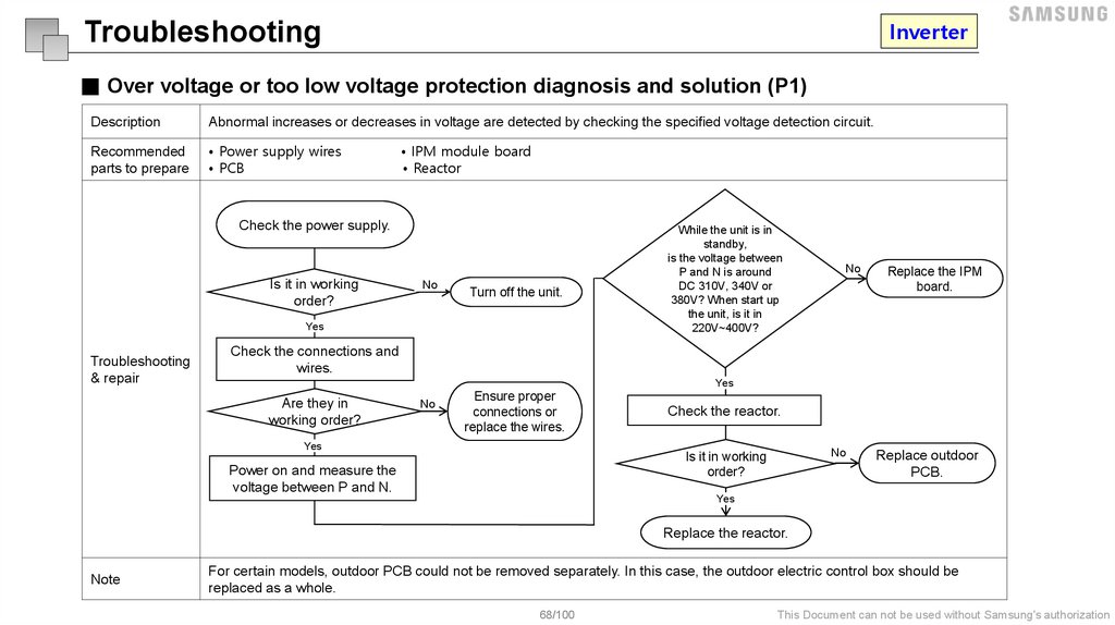
■ Over voltage or too low voltage protection diagnosis and solution (P1)
Description
Abnormal increases or decreases in voltage are detected by checking the specified voltage detection circuit.
Recommended
parts to prepare
• Power supply wires
• PCB
• IPM module board
• Reactor
Check the power supply.
Is it in working
order?
No
Turn off the unit.
Yes
Troubleshooting
& repair
While the unit is in
standby,
is the voltage between
P and N is around
DC 310V, 340V or
380V? When start up
the unit, is it in
220V~400V?
No
Replace the IPM
board.
Check the connections and
wires.
Yes
Are they in
working order?
No
Ensure proper
connections or
replace the wires.
Yes
Check the reactor.
No
Is it in working
order?
Power on and measure the
voltage between P and N.
Replace outdoor
PCB.
Yes
Replace the reactor.
Note
For certain models, outdoor PCB could not be removed separately. In this case, the outdoor electric control box should be
replaced as a whole.
68/100
This Document can not be used without Samsung's authorization
69.
InverterTroubleshooting
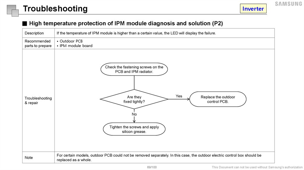
■ High temperature protection of IPM module diagnosis and solution (P2)
Description
If the temperature of IPM module is higher than a certain value, the LED will display the failure.
Recommended
parts to prepare
• Outdoor PCB
• IPM module board
Check the fastening screws on the
PCB and IPM radiator.
Troubleshooting
& repair
Yes
Are they
fixed tightly?
Replace the outdoor
control PCB.
No
Tighten the screws and apply
silicon grease.
Note
For certain models, outdoor PCB could not be removed separately. In this case, the outdoor electric control box should be
replaced as a whole.
69/100
This Document can not be used without Samsung's authorization
70.
InverterTroubleshooting
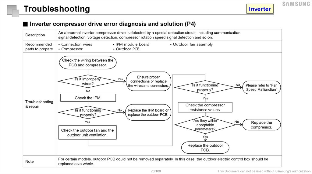
■ Inverter compressor drive error diagnosis and solution (P4)
Description
An abnormal inverter compressor drive is detected by a special detection circuit, including communication
signal detection, voltage detection, compressor rotation speed signal detection and so on.
Recommended
parts to prepare
• Connection wires
• Compressor
• IPM module board
• Outdoor PCB
• Outdoor fan assembly
Check the wiring between the
PCB and compressor.
Is it improperly
wired?
Yes
Ensure proper
connections or replace
the wires and connectors.
No
Is it functioning
properly?
Check the IPM.
Yes
Troubleshooting
& repair
Is it functioning
properly?
No
Replace the IPM board or
replace the outdoor PCB.
Check the outdoor fan and the
outdoor unit ventilation.
Please refer to “Fan
Speed Malfunction”
No
Replace the
compressor.
Check the compressor
resistance values.
Are they within
acceptable
parameters?
Yes
No
Yes
Replace the outdoor
PCB.
Note
For certain models, outdoor PCB could not be removed separately. In this case, the outdoor electric control box should be
replaced as a whole.
70/100
This Document can not be used without Samsung's authorization
71.
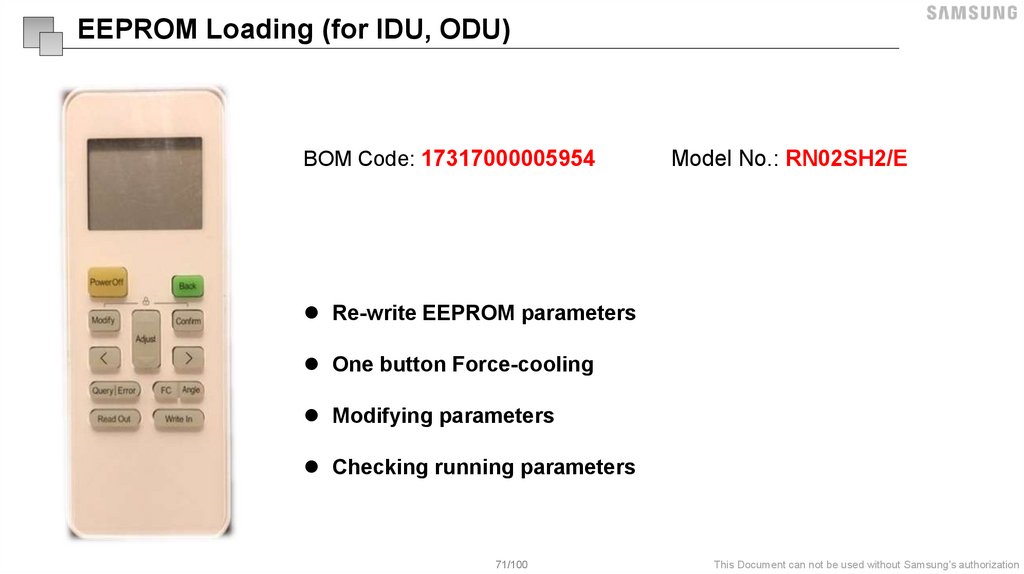
EEPROM Loading (for IDU, ODU)BOM Code: 17317000005954
Model No.: RN02SH2/E
Re-write EEPROM parameters
One button Force-cooling
Modifying parameters
Checking running parameters
71/100
This Document can not be used without Samsung's authorization
72.
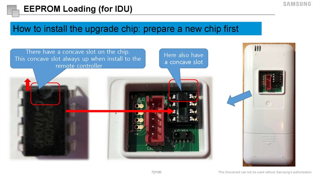
EEPROM Loading (for IDU)How to install the upgrade chip: prepare a new chip first
There have a concave slot on the chip.
This concave slot always up when install to the
remote controller
Here also have
a concave slot
72/100
This Document can not be used without Samsung's authorization
73.
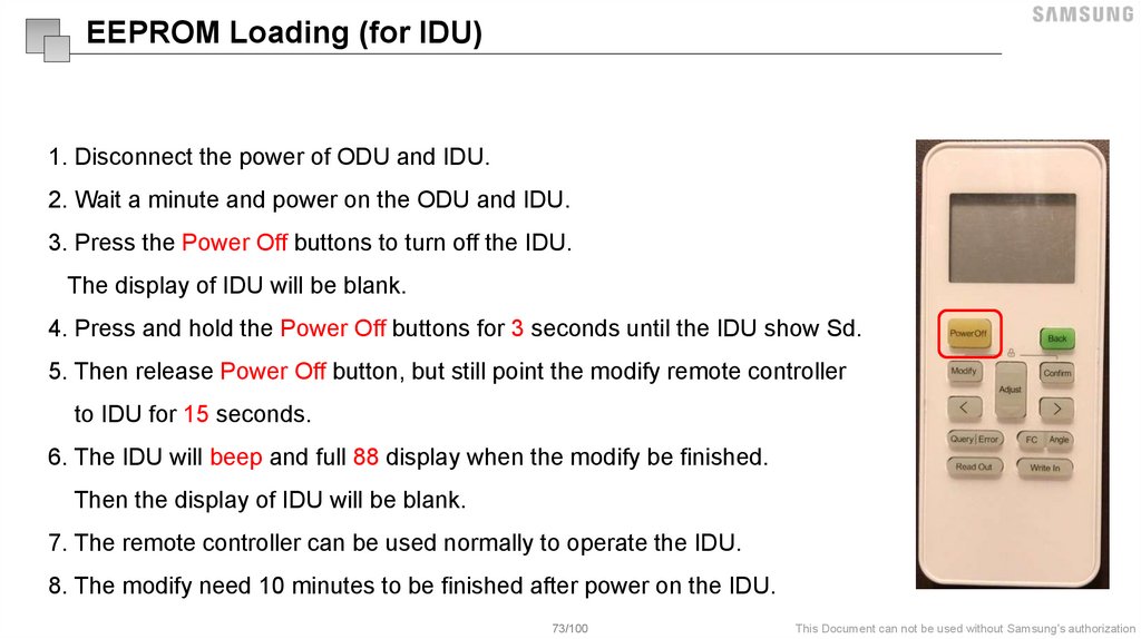
EEPROM Loading (for IDU)1. Disconnect the power of ODU and IDU.
2. Wait a minute and power on the ODU and IDU.
3. Press the Power Off buttons to turn off the IDU.
The display of IDU will be blank.
4. Press and hold the Power Off buttons for 3 seconds until the IDU show Sd.
5. Then release Power Off button, but still point the modify remote controller
to IDU for 15 seconds.
6. The IDU will beep and full 88 display when the modify be finished.
Then the display of IDU will be blank.
7. The remote controller can be used normally to operate the IDU.
8. The modify need 10 minutes to be finished after power on the IDU.
73/100
This Document can not be used without Samsung's authorization
74.
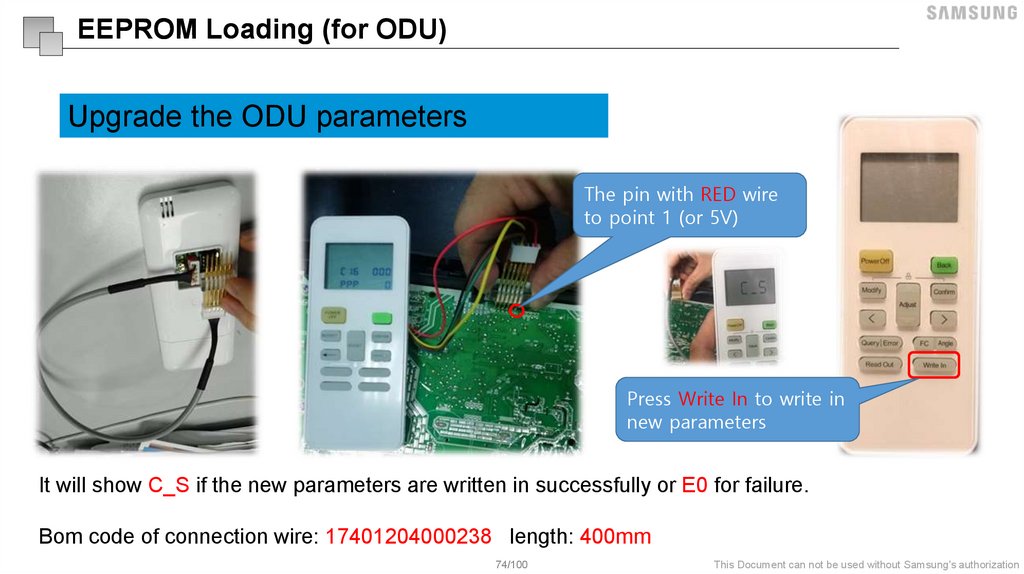
EEPROM Loading (for ODU)Upgrade the ODU parameters
The pin with RED wire
to point 1 (or 5V)
Press Write In to write in
new parameters
It will show C_S if the new parameters are written in successfully or E0 for failure.
Bom code of connection wire: 17401204000238 length: 400mm
74/100
This Document can not be used without Samsung's authorization
75.
Disassembly & Reassembly76.
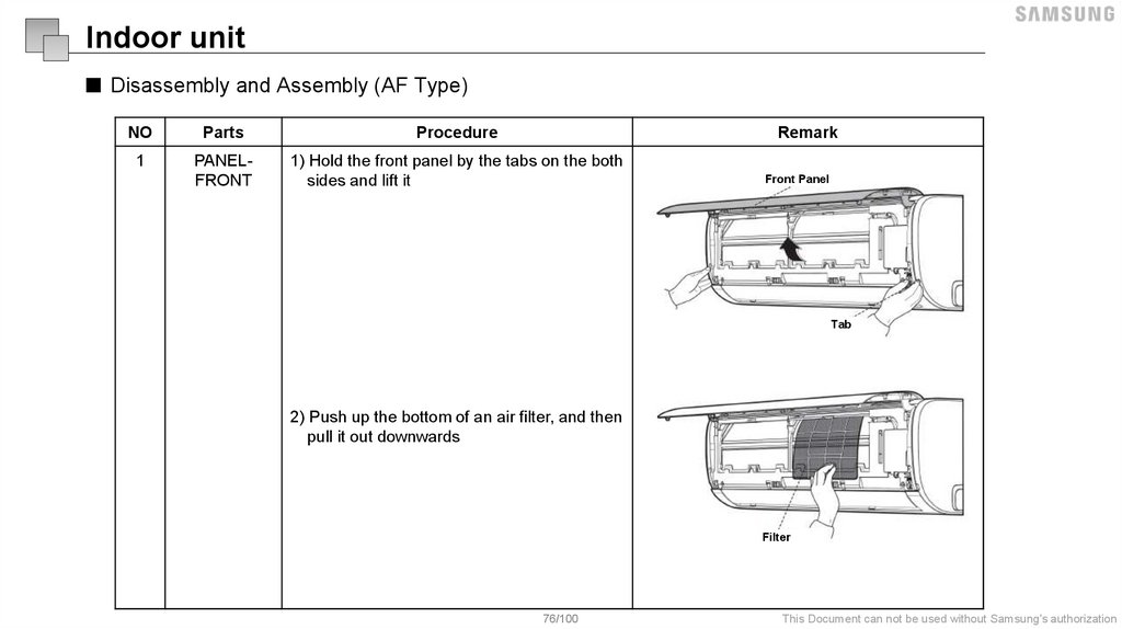
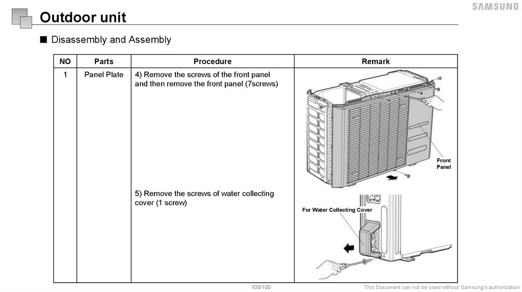
Indoor unit■ Disassembly and Assembly (AF Type)
NO
Parts
Procedure
Remark
1
PANELFRONT
1) Hold the front panel by the tabs on the both
sides and lift it
Front Panel
Tab
2) Push up the bottom of an air filter, and then
pull it out downwards
Filter
76/100
This Document can not be used without Samsung's authorization
77.
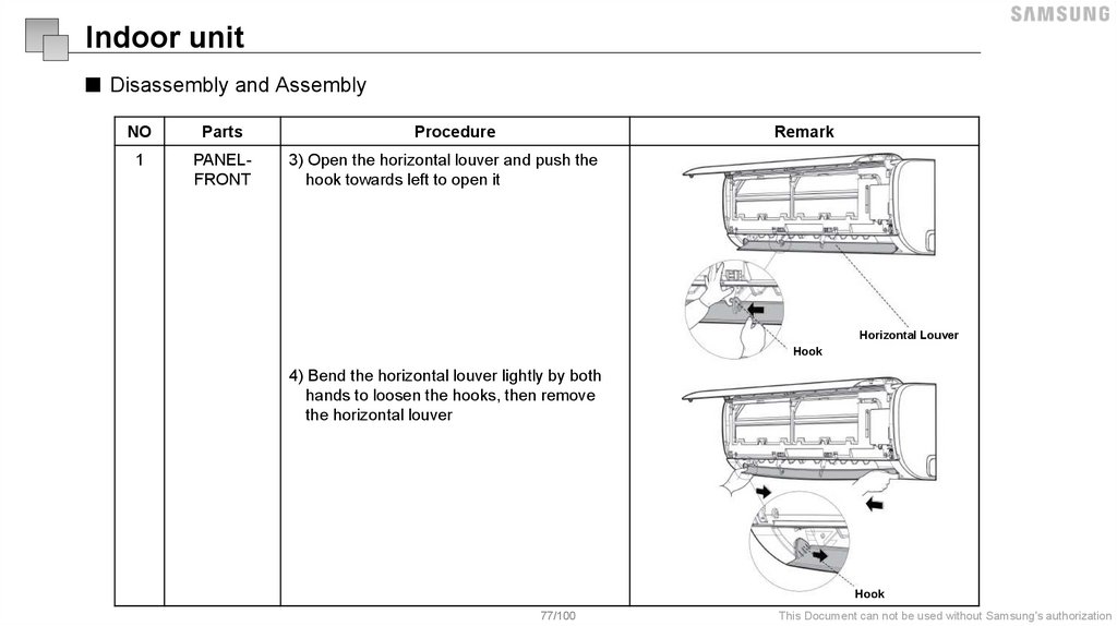
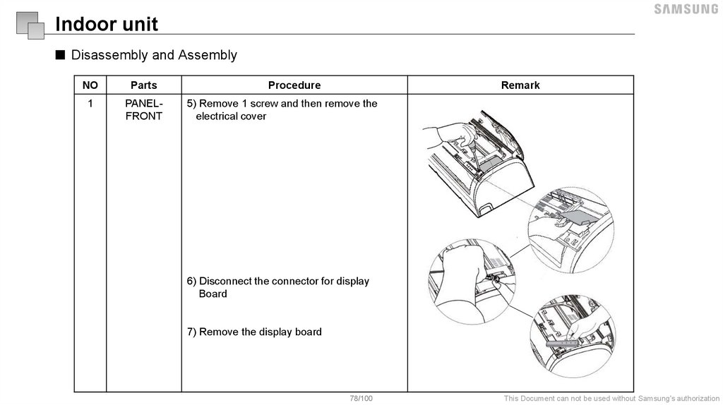
Indoor unit■ Disassembly and Assembly
NO
Parts
1
PANELFRONT
Procedure
Remark
3) Open the horizontal louver and push the
hook towards left to open it
Horizontal Louver
Hook
4) Bend the horizontal louver lightly by both
hands to loosen the hooks, then remove
the horizontal louver
Hook
77/100
This Document can not be used without Samsung's authorization
78.
Indoor unit■ Disassembly and Assembly
NO
Parts
1
PANELFRONT
Procedure
Remark
5) Remove 1 screw and then remove the
electrical cover
6) Disconnect the connector for display
Board
7) Remove the display board
78/100
This Document can not be used without Samsung's authorization
79.
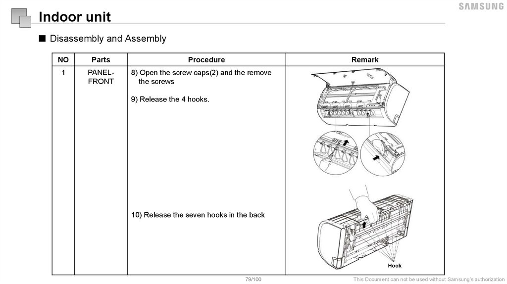
Indoor unit■ Disassembly and Assembly
NO
Parts
Procedure
Remark
1
PANELFRONT
8) Open the screw caps(2) and the remove
the screws
9) Release the 4 hooks.
10) Release the seven hooks in the back
Hook
79/100
This Document can not be used without Samsung's authorization
80.
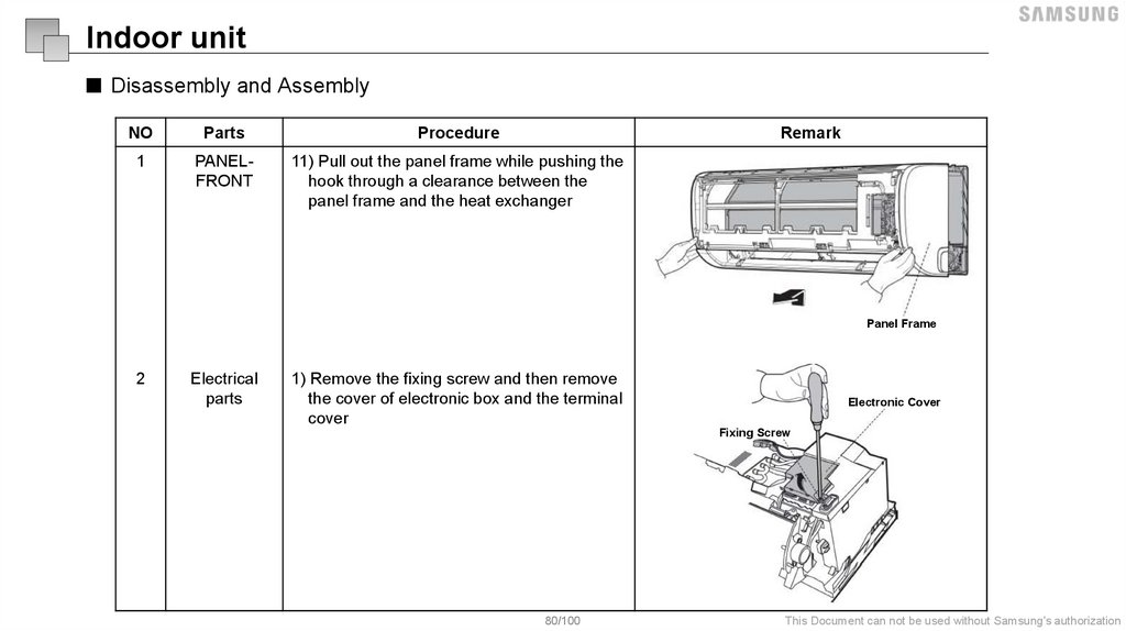
Indoor unit■ Disassembly and Assembly
NO
Parts
Procedure
Remark
1
PANELFRONT
11) Pull out the panel frame while pushing the
hook through a clearance between the
panel frame and the heat exchanger
Panel Frame
2
Electrical
parts
1) Remove the fixing screw and then remove
the cover of electronic box and the terminal
cover
Electronic Cover
Fixing Screw
80/100
This Document can not be used without Samsung's authorization
81.
Indoor unit■ Disassembly and Assembly
NO
Parts
Procedure
Remark
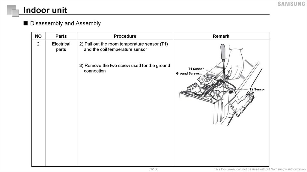
2
Electrical
parts
2) Pull out the room temperature sensor (T1)
and the coil temperature sensor
3) Remove the two screw used for the ground
connection
T1 Sensor
Ground Screws
T2 Sensor
81/100
This Document can not be used without Samsung's authorization
82.
Indoor unit■ Disassembly and Assembly
NO
Parts
2
Electrical
parts
Procedure
Remark
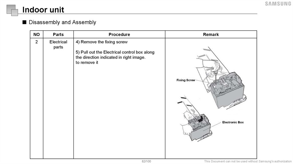
4) Remove the fixing screw
5) Pull out the Electrical control box along
the direction indicated in right image.
to remove it
Fixing Screw
T1 Sensor
Electronic Box
82/100
This Document can not be used without Samsung's authorization
83.
Indoor unit■ Disassembly and Assembly
NO
Parts
2
Electrical
parts
Procedure
Remark
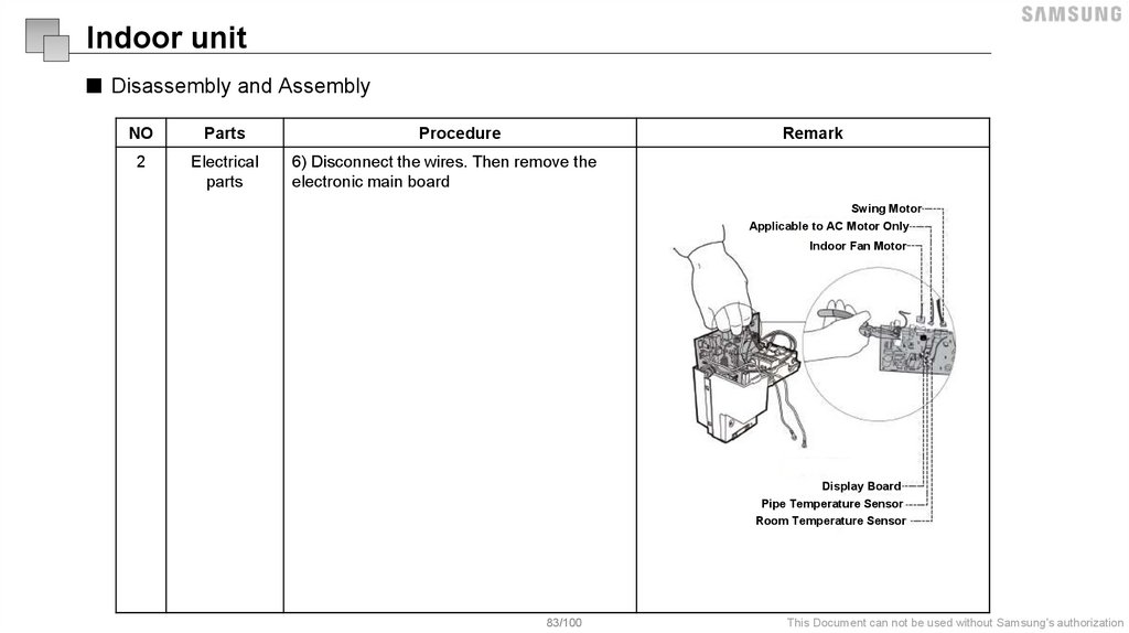
6) Disconnect the wires. Then remove the
electronic main board
Swing Motor
Applicable to AC Motor Only
Indoor Fan Motor
T1 Sensor
Display Board
Pipe Temperature Sensor
Room Temperature Sensor
83/100
This Document can not be used without Samsung's authorization
84.
Indoor unit■ Disassembly and Assembly
NO
Parts
2
Electrical
parts
Procedure
Remark
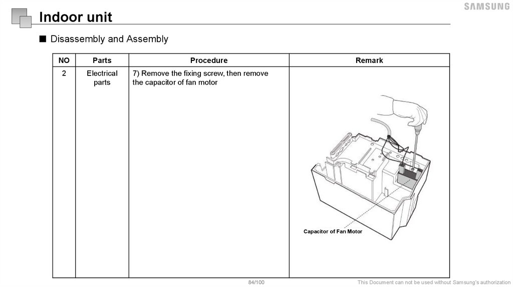
7) Remove the fixing screw, then remove
the capacitor of fan motor
Capacitor of Fan Motor
84/100
This Document can not be used without Samsung's authorization
85.
Indoor unit■ Disassembly and Assembly
NO
Parts
Procedure
Remark
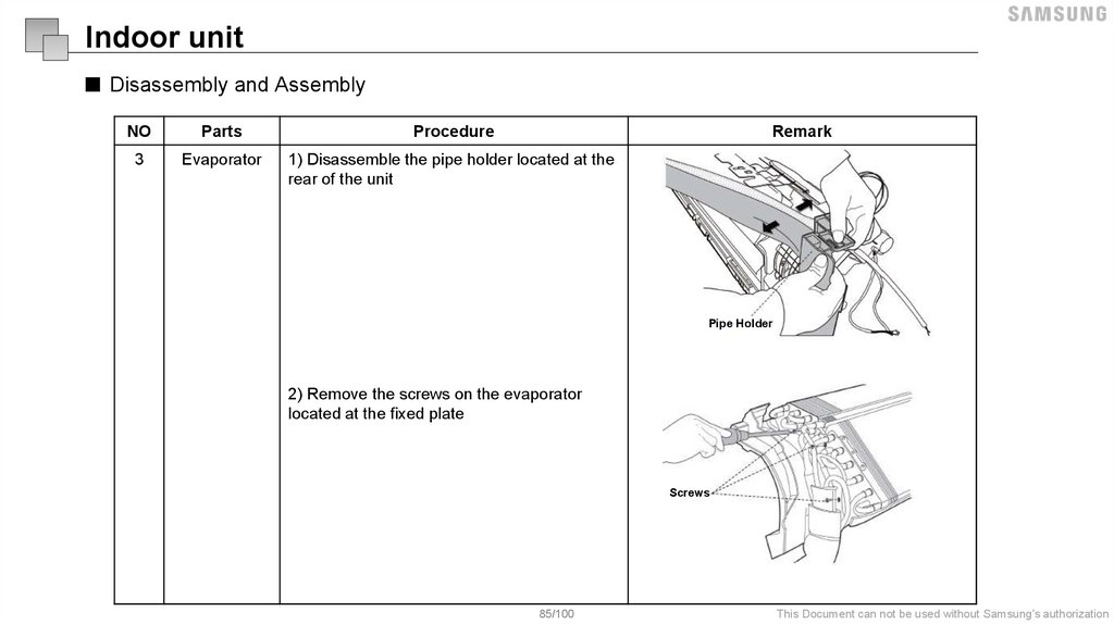
3
Evaporator
1) Disassemble the pipe holder located at the
rear of the unit
Pipe Holder
2) Remove the screws on the evaporator
located at the fixed plate
Screws
85/100
This Document can not be used without Samsung's authorization
86.
Indoor unit■ Disassembly and Assembly
NO
Parts
Procedure
Remark
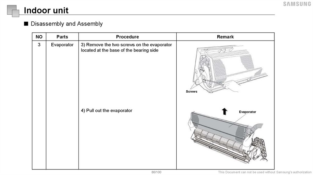
3
Evaporator
3) Remove the two screws on the evaporator
located at the base of the bearing side
Screws
4) Pull out the evaporator
Evaporator
86/100
This Document can not be used without Samsung's authorization
87.
Indoor unit■ Disassembly and Assembly
NO
Parts
Procedure
Remark
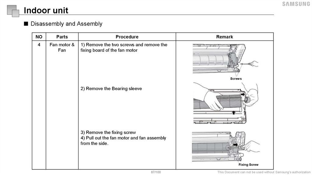
4
Fan motor &
Fan
1) Remove the two screws and remove the
fixing board of the fan motor
Screws
2) Remove the Bearing sleeve
3) Remove the fixing screw
4) Pull out the fan motor and fan assembly
from the side.
Fixing Screw
87/100
This Document can not be used without Samsung's authorization
88.
Indoor unit■ Disassembly and Assembly
NO
Parts
Procedure
Remark
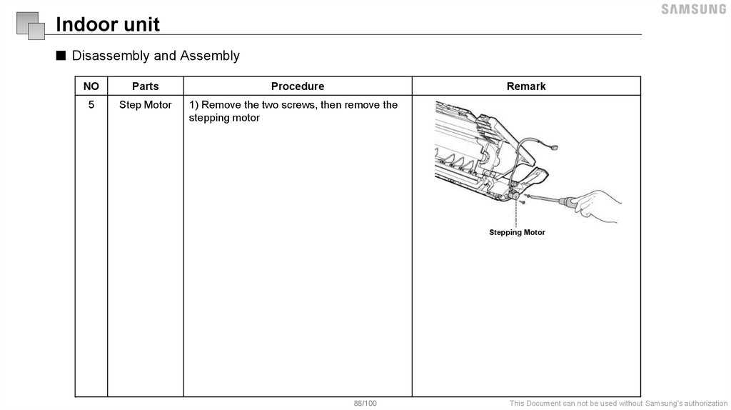
5
Step Motor
1) Remove the two screws, then remove the
stepping motor
Stepping Motor
88/100
This Document can not be used without Samsung's authorization
89.
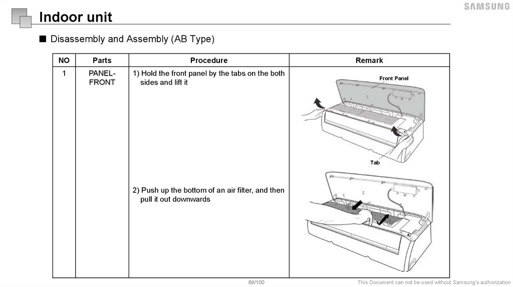
Indoor unit■ Disassembly and Assembly (AB Type)
NO
Parts
Procedure
Remark
1
PANELFRONT
1) Hold the front panel by the tabs on the both
sides and lift it
Front Panel
Tab
2) Push up the bottom of an air filter, and then
pull it out downwards
89/100
This Document can not be used without Samsung's authorization
90.
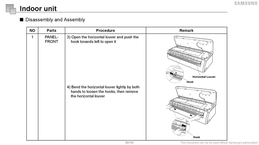
Indoor unit■ Disassembly and Assembly
NO
Parts
1
PANELFRONT
Procedure
Remark
3) Open the horizontal louver and push the
hook towards left to open it
Horizontal Louver
Hook
4) Bend the horizontal louver lightly by both
hands to loosen the hooks, then remove
the horizontal louver
Hook
90/100
This Document can not be used without Samsung's authorization
91.
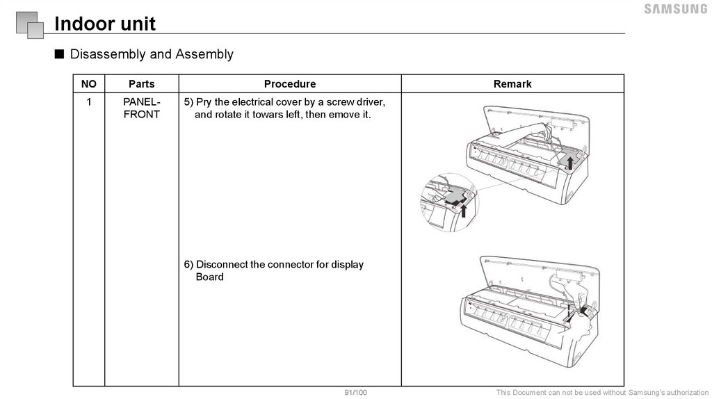
Indoor unit■ Disassembly and Assembly
NO
Parts
Procedure
Remark
1
PANELFRONT
5) Pry the electrical cover by a screw driver,
and rotate it towars left, then emove it.
6) Disconnect the connector for display
Board
91/100
This Document can not be used without Samsung's authorization
92.
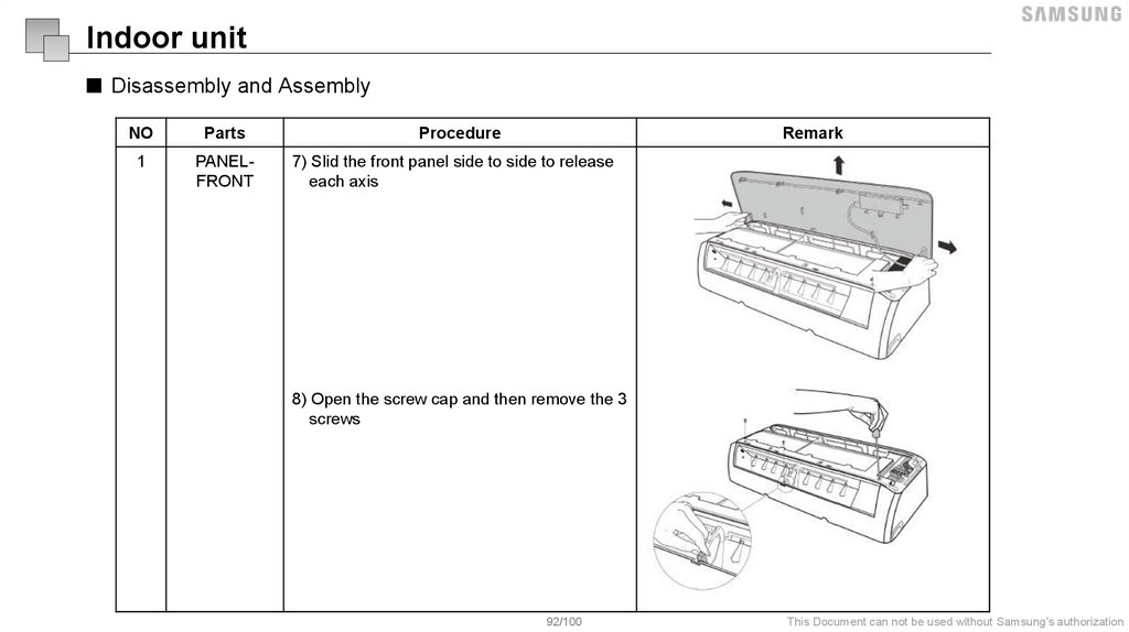
Indoor unit■ Disassembly and Assembly
NO
Parts
Procedure
Remark
1
PANELFRONT
7) Slid the front panel side to side to release
each axis
8) Open the screw cap and then remove the 3
screws
92/100
This Document can not be used without Samsung's authorization
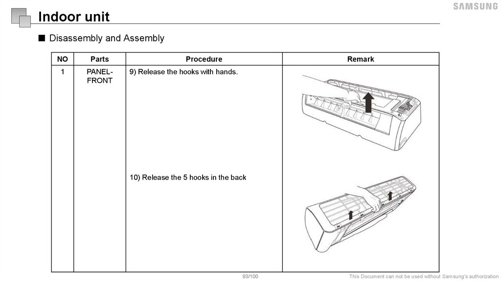
93.
Indoor unit■ Disassembly and Assembly
NO
Parts
1
PANELFRONT
Procedure
Remark
9) Release the hooks with hands.
10) Release the 5 hooks in the back
93/100
This Document can not be used without Samsung's authorization
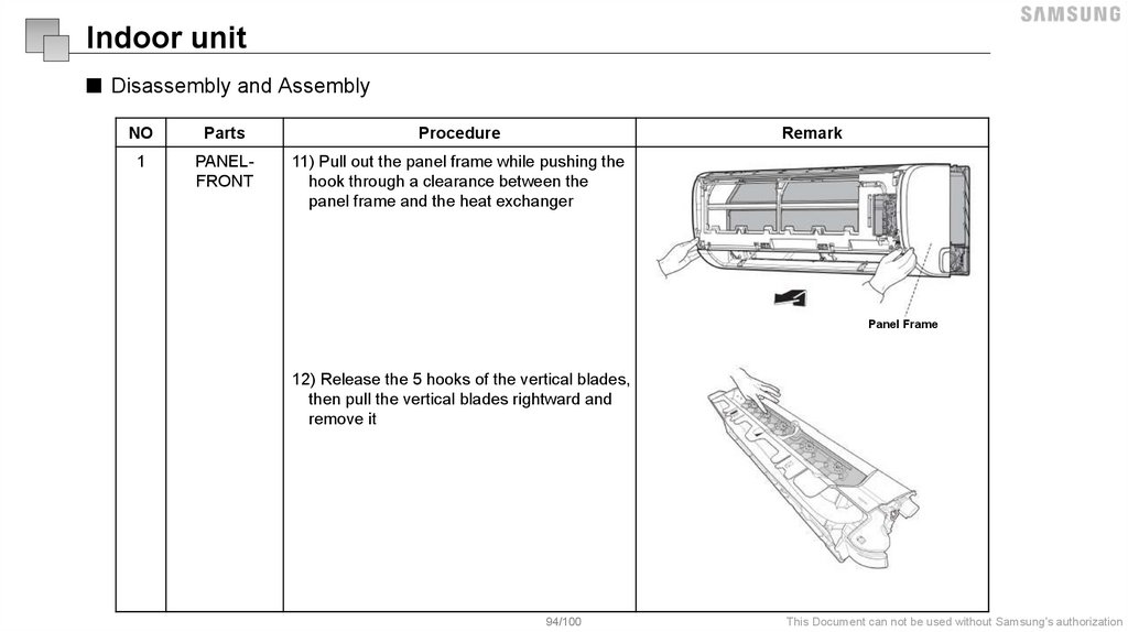
94.
Indoor unit■ Disassembly and Assembly
NO
Parts
Procedure
Remark
1
PANELFRONT
11) Pull out the panel frame while pushing the
hook through a clearance between the
panel frame and the heat exchanger
Panel Frame
12) Release the 5 hooks of the vertical blades,
then pull the vertical blades rightward and
remove it
94/100
This Document can not be used without Samsung's authorization
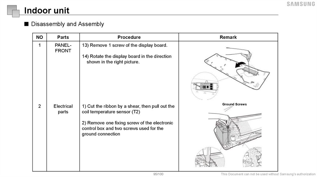
95.
Indoor unit■ Disassembly and Assembly
NO
Parts
1
PANELFRONT
Procedure
Remark
13) Remove 1 screw of the display board.
14) Rotate the display board in the direction
shown in the right picture.
2
Electrical
parts
1) Cut the ribbon by a shear, then pull out the
coil temperature sensor (T2)
Ground Screws
2) Remove one fixing screw of the electronic
control box and two screws used for the
ground connection
95/100
This Document can not be used without Samsung's authorization
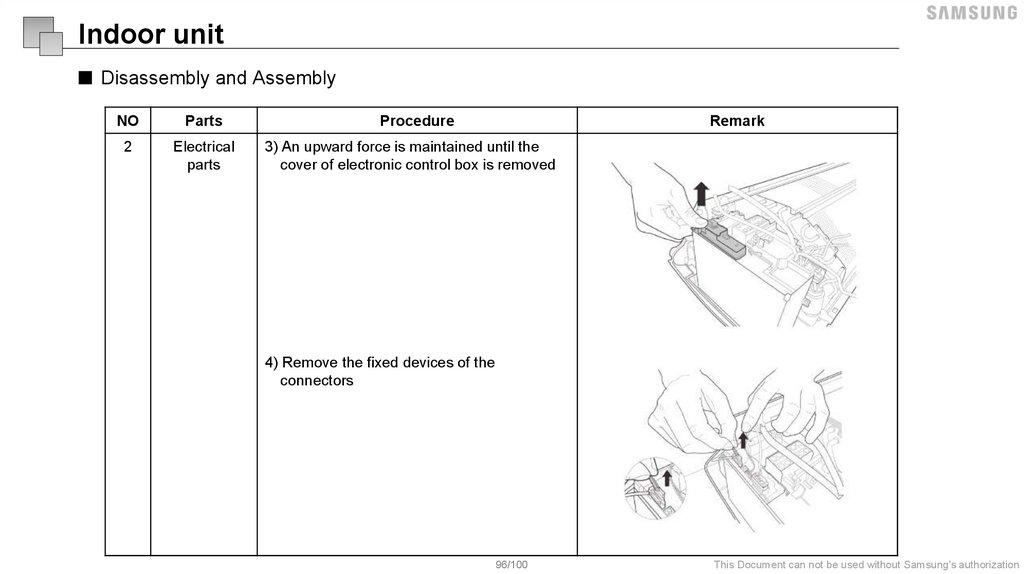
96.
Indoor unit■ Disassembly and Assembly
NO
Parts
Procedure
Remark
2
Electrical
parts
3) An upward force is maintained until the
cover of electronic control box is removed
4) Remove the fixed devices of the
connectors
96/100
This Document can not be used without Samsung's authorization
97.
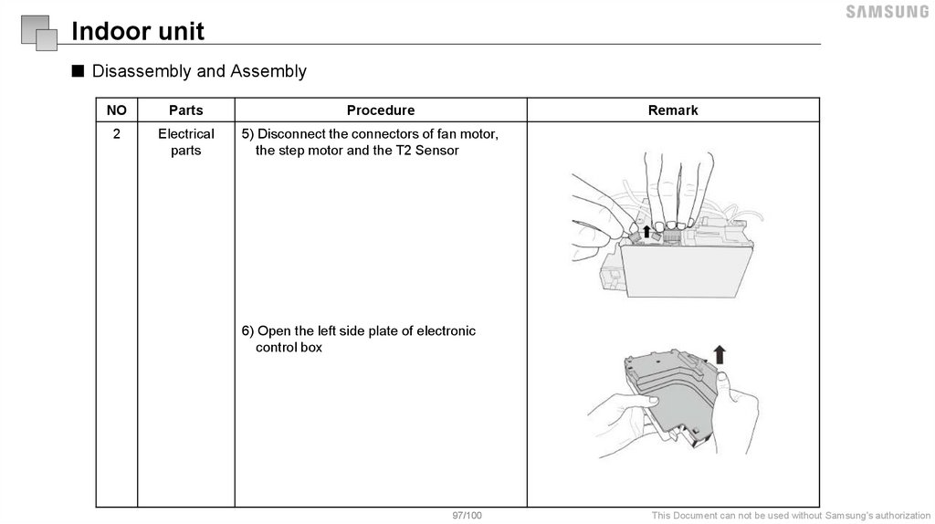
Indoor unit■ Disassembly and Assembly
NO
Parts
2
Electrical
parts
Procedure
Remark
5) Disconnect the connectors of fan motor,
the step motor and the T2 Sensor
6) Open the left side plate of electronic
control box
97/100
This Document can not be used without Samsung's authorization
98.
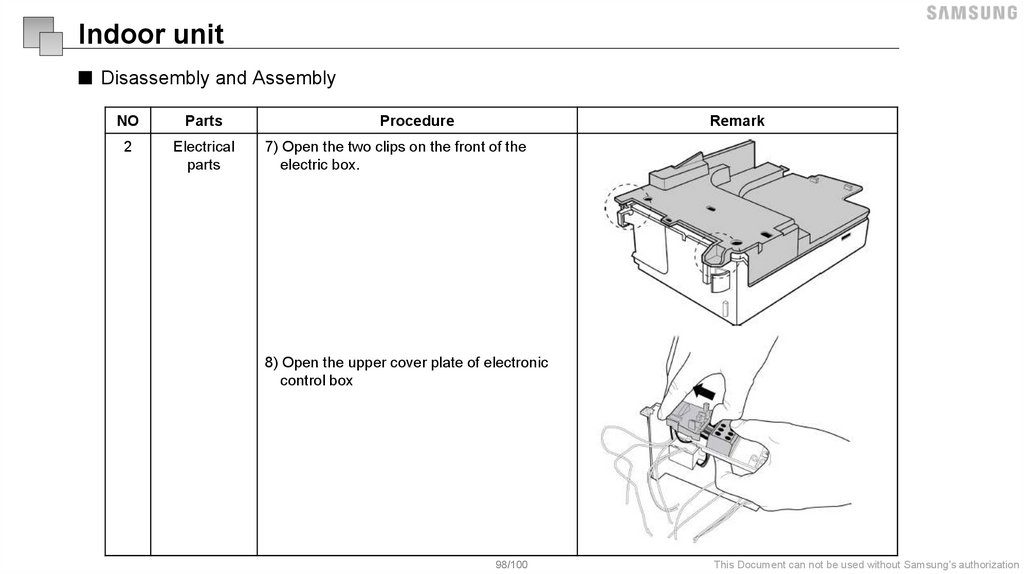
Indoor unit■ Disassembly and Assembly
NO
Parts
2
Electrical
parts
Procedure
Remark
7) Open the two clips on the front of the
electric box.
8) Open the upper cover plate of electronic
control box
98/100
This Document can not be used without Samsung's authorization
99.
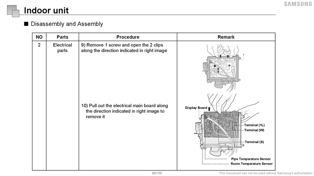
Indoor unit■ Disassembly and Assembly
NO
Parts
2
Electrical
parts
Procedure
Remark
9) Remove 1 screw and open the 2 clips
along the direction indicated in right image
10) Pull out the electrical main board along
the direction indicated in right image to
remove it
Display Board
Terminal (1L)
Terminal (W)
T1 Sensor
Terminal (S)
Pipe Temperature Sensor
Room Temperature Sensor
99/100
This Document can not be used without Samsung's authorization
100.
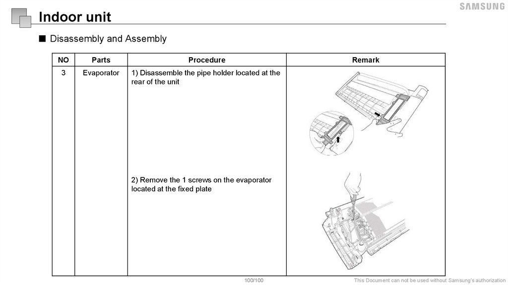
Indoor unit■ Disassembly and Assembly
NO
Parts
Procedure
Remark
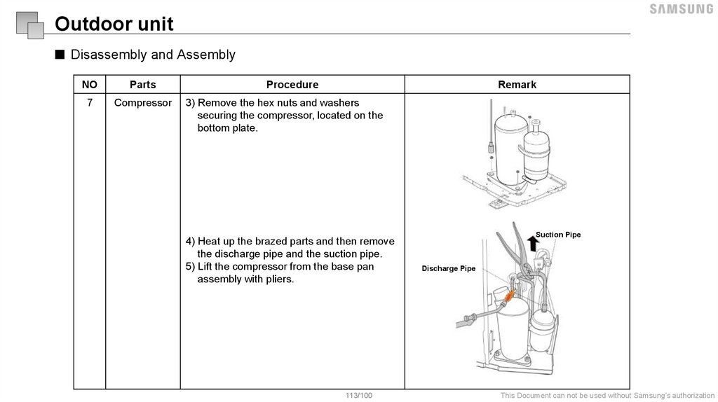
3
Evaporator
1) Disassemble the pipe holder located at the
rear of the unit
2) Remove the 1 screws on the evaporator
located at the fixed plate
100/100
This Document can not be used without Samsung's authorization
101.
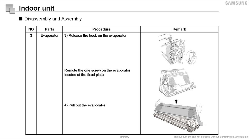
Indoor unit■ Disassembly and Assembly
NO
Parts
3
Evaporator
Procedure
Remark
3) Release the hook on the evaporator
Remote the one screw on the evaporator
located at the fixed plate
4) Pull out the evaporator
101/100
This Document can not be used without Samsung's authorization
102.
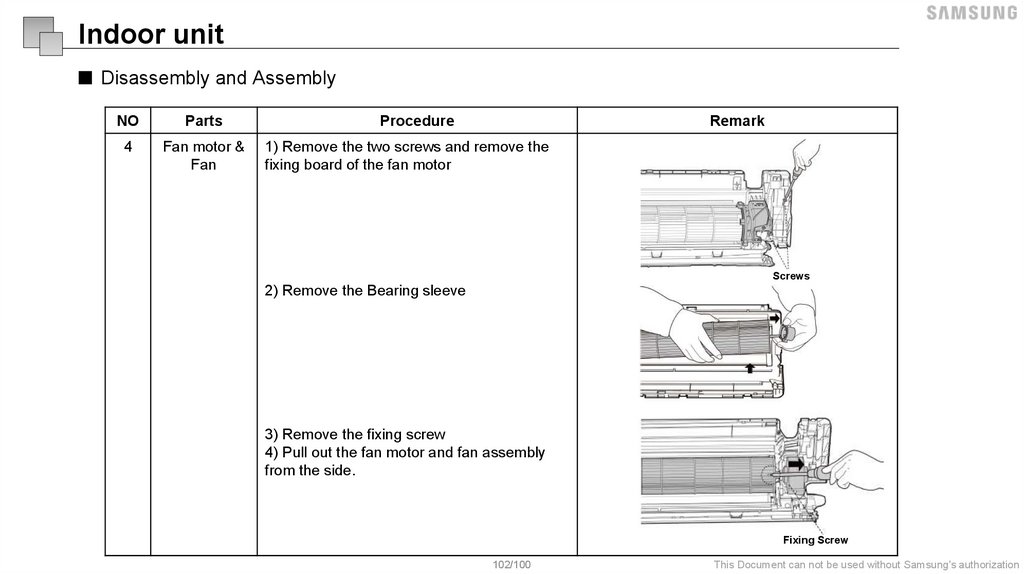
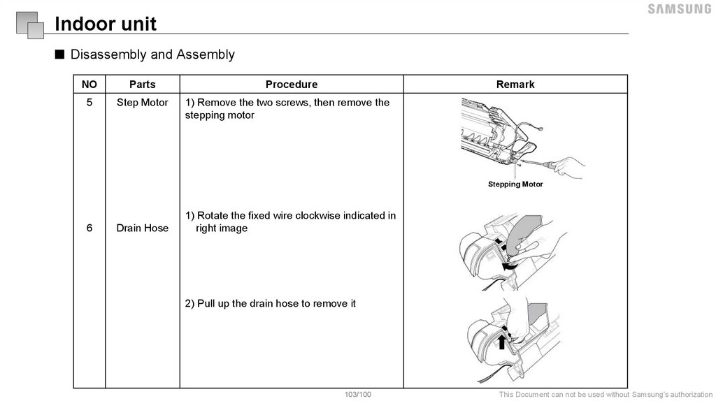
Indoor unit■ Disassembly and Assembly
NO
Parts
Procedure
Remark
4
Fan motor &
Fan
1) Remove the two screws and remove the
fixing board of the fan motor
Screws
2) Remove the Bearing sleeve
3) Remove the fixing screw
4) Pull out the fan motor and fan assembly
from the side.
Fixing Screw
102/100
This Document can not be used without Samsung's authorization
103.
Indoor unit■ Disassembly and Assembly
NO
Parts
Procedure
Remark
5
Step Motor
1) Remove the two screws, then remove the
stepping motor
Stepping Motor
6
Drain Hose
1) Rotate the fixed wire clockwise indicated in
right image
2) Pull up the drain hose to remove it
103/100
This Document can not be used without Samsung's authorization
104.
Outdoor unit■ Disassembly and Assembly
NO
Parts
Procedure
Remark
1
Panel Plate
1) Turn off the air conditioner and the power
breaker.
2) Remove the screws of the big handle
and then remove the big handle (1 screws)
Big Handle
For US models (3 screws)
3) Remove the screws of the top cover and
then remove the top cover (3screws). One of
the screws is located underneath the big
handle
104/100
Top Cover
This Document can not be used without Samsung's authorization
105.
Outdoor unit■ Disassembly and Assembly
NO
Parts
1
Panel Plate
Procedure
Remark
4) Remove the screws of the front panel
and then remove the front panel (7screws)
Front
Panel
5) Remove the screws of water collecting
cover (1 screw)
For Water Collecting Cover
105/100
This Document can not be used without Samsung's authorization
106.
Outdoor unit■ Disassembly and Assembly
NO
Parts
Procedure
Remark
1
Panel Plate
6) Remove the screws of the rear net and
then remove the rear net (2screws) (for some
models)
7) Remove the screws of the right panel and
then remove the right panel (6 screws)
Right Panel
106/100
This Document can not be used without Samsung's authorization
107.
Outdoor unit■ Disassembly and Assembly
NO
Parts
2.1
PCB board
(9/12K)
Procedure
Remark
1) Remove the screws of the top cover.
(2 screws)
2) Unfix the hooks and then open the
electronic control box cover (4 hooks)
3) Disconnect the connector for fan motor
from the electronic control board
4) Remove the connector for the
5) Pull out the two blue wires connected with
the four way valve
6) Pull out connectors of the condenser coil
temp. sensor(T3),outdoor ambient temp.
sensor(T4) and discharge temp. sensor(TP)
7) Disconnect the electronic expansion
valve wire
8) Then remove the electronic control board.
4-Way Valve
AC Fan
Compressor
T3, T4, TP
DC Fan
Electronic Expansion Valve
107/100
This Document can not be used without Samsung's authorization
108.
Outdoor unit■ Disassembly and Assembly
NO
Parts
2.2
PCB board
(18~24K)
Procedure
Remark
1) Unfix the hooks and then open the
electronic control box cover (4 hooks)
2) Disconnect the connector for fan motor
from the electronic control board.
3) Remove the connector for the compressor.
4) Pull out the two blue wires connected with
the four way valve.
5) Pull out connectors of the condenser coil
temp. sensor(T3),outdoor ambient temp.
sensor(T4) and discharge temp. sensor(TP)
6) Disconnect the electronic expansion
valve wire.
7) Then remove the electronic control board.
108/100
4-Way Valve
Reactor
DR
AC Fan
DC Fan
Compressor
T3, T4, TP
Electronic Expansion Valve
This Document can not be used without Samsung's authorization
109.
Outdoor unit■ Disassembly and Assembly
NO
Parts
3
Fan
Assembly
Procedure
Remark
1) Remove the nut securing the fan with a
spanner.
2) Remove the fan.
D-cut
4
Fan Motor
3) Remove the fixing screws of the fan motor
(4 screws).
4) Remove the fan motor.
109/100
This Document can not be used without Samsung's authorization
110.
Outdoor unit■ Disassembly and Assembly
NO
Parts
Procedure
Remark
5
Sound
blanked
1) Remove the sound blanket (side and top)
Sound Blanket(top)
Sound Blanket(side)
110/100
This Document can not be used without Samsung's authorization
111.
Outdoor unit■ Disassembly and Assembly
NO
Parts
Procedure
Remark
6
Four-way
valve
(for H/P
models)
1) Heat up the brazed parts and then detach
the four-way valve and the pipe.
2) Remove the four-way valve assembly with
pliers.
111/100
This Document can not be used without Samsung's authorization
112.
Outdoor unit■ Disassembly and Assembly
NO
Parts
7
Compressor
Procedure
Remark
1) Remove the flange nut of terminal cover
and remove the terminal cover.
Terminal Cover
2) Disconnect the connectors
112/100
This Document can not be used without Samsung's authorization
113.
Outdoor unit■ Disassembly and Assembly
NO
Parts
7
Compressor
Procedure
Remark
3) Remove the hex nuts and washers
securing the compressor, located on the
bottom plate.
4) Heat up the brazed parts and then remove
the discharge pipe and the suction pipe.
5) Lift the compressor from the base pan
assembly with pliers.
113/100
Suction Pipe
Discharge Pipe
This Document can not be used without Samsung's authorization
114.
Nomenclature115.
NomenclatureModel Name
AR
12
T
X
H
QA
WK
N
UA
(1)
(2)
(3)
(4)
(5)
(6)
(7)
(8)
Buyer
AR
RAC
BTU
x 1000
(3) Year
M
2017
N
2018
R
2019
T
2020
A
2021
B
2022
C
2023
LA
ODM RAC (T) 1st Model
WK
White
LB
ODM RAC (T) 2nd Model
SI
Silver
QA
ODM RAC (M) 1st Model
UR
Midnight Blue
QB
ODM RAC (M) 2nd Model
QC
RA
S Inverter HP R410A
E
Wifi + eco Filter
V Inverter CO R410A
F
Wifi
X
Inverter HP R32
G
Eco Filter
Y
Inverter CO R32
H
No Option
Q
Fixed HP R410A
3
India 3Star
R
Fixed CO R410A
5
India 5Star
H
Fixed HP R32
G
Fixed CO R32
BR
Rich Brown
rd
BU
Cool Blue
st
PU
Pastel Blue
ODM RAC (M) 3 Model
ODM RAC (Au) 1 Model
st
BA
ODM RAC (Am) 1 Model
BB
ODM RAC (Am) 2nd Model
GA
ODM RAC (G) 1st Model
GB
ODM RAC (G) 2nd Model
(5) Feature 2
(4) Feature 1
(7) Color
(6) Series (Version)
(1) Classification (2) Capacity (2Digit)
115/100
(8) SET
/
SET
N
IN
X
OUT
This Document can not be used without Samsung's authorization
116.
AppendixFile Name
[TM] SOL_DMS 2.5(MIM-D01AN)_Installation_GL_EN_2016_Ver1.0
(1)
(2)
(3)
(1) Classification
TM
(5)
(2) Product 1
Training manual
VRF
Single
FJM
Water
SOL
Accessory
(5) Category
Integration
Product
Installation
Troubleshooting
Control logic
(4)
(6) Region
GL
EU
NA
LA
EA
WA
ME
CN
AF
KR
Global
Europe
North America
Latin America
S.E Asia
S.W Asia
MENA
China
Africa
Korea
(6)
(3) Product 2
DVM S
DVM S Indoor unit
Inverter
Non Inverter
General
EHS
DVM Water
DVM Chiller
DMS 2.5
Accessory product
English
Spanish
Chinese
French
German
Korea
(8)
(9)
(4) Model code (or Skip)
Standard / High ambient / ETC
Indoor unit / Hydro / ETC
Standard
Controller name
-
(7) Language
EN
ES
CH
FR
DE
KR
(7)
(8) Year
2016
2017
2018
2019
2020
MWR-WE10N
MR-KH00E
MRW-TA
MIM-D01AN
MIM-F00N
MCM-A300N
(9) Version
Ver1.00
Ver1.01
Ver1.02
Ver1.10
Ver2.00
Minor : 0.01 increment
Major : 1.00 increment
※ If change the year, initialization
(Ver1.00)
117.
This Training Manual is a property of Samsung Electronics Co.,Ltd.Any unauthorized use of Manual can be punished under applicable International and/or domestic law.