

 electronics
Similar presentations:


HW-M550 TRAINING MANUAL Ver. 1.1 (updated 20180625) Wireless Audio - Soundbar ’2017 SAMSUNG ELECTRONICS CO.,LTD. VD R&D GROUP
1.
HW-M550 TRAININGMANUAL
Ver. 1.1 (updated 20180625)
Wireless Audio - Soundbar
’2017
SAMSUNG ELECTRONICS CO.,LTD.
VD R&D GROUP
1
2.
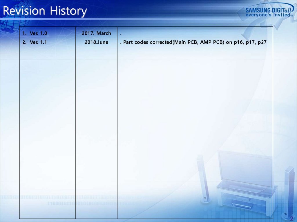
Revision History1. Ver. 1.0
2017. March
.
2. Ver. 1.1
2018.June
. Part codes corrected(Main PCB, AMP PCB) on p16, p17, p27
2
3.
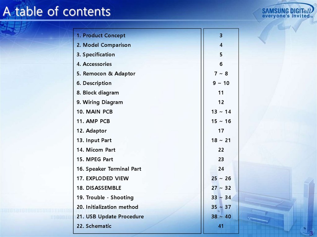
A table of contents1. Product Concept
3
2. Model Comparison
4
3. Specification
5
4. Accessories
6
5. Remocon & Adaptor
7~8
6. Description
9 ~ 10
8. Block diagram
11
9. Wiring Diagram
12
10. MAIN PCB
13 ~ 14
11. AMP PCB
15 ~ 16
12. Adaptor
17
13. Input Part
18 ~ 21
14. Micom Part
22
15. MPEG Part
23
16. Speaker Terminal Part
24
17. EXPLODED VIEW
25 ~ 26
18. DISASSEMBLE
27 ~ 32
19. Trouble - Shooting
33 ~ 34
20. Initialization method
35 ~ 37
21. USB Update Procedure
38 ~ 40
22. Schematic
41
3
4.
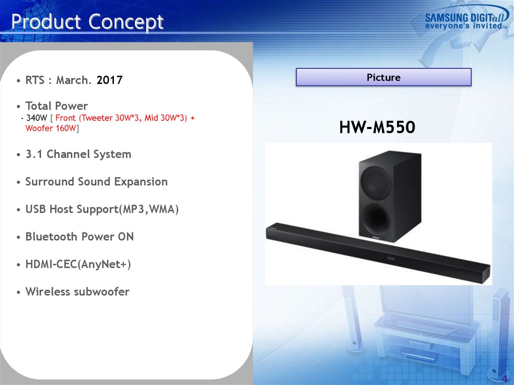
Product Concept• RTS : March. 2017
Picture
• Total Power
- 340W [ Front (Tweeter 30W*3, Mid 30W*3) +
Woofer 160W]
HW-M550
• 3.1 Channel System
• Surround Sound Expansion
• USB Host Support(MP3,WMA)
• Bluetooth Power ON
• HDMI-CEC(AnyNet+)
• Wireless subwoofer
4
5.
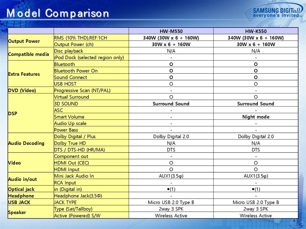
M od el Com p arisonOutput Power
Compatible media
Extra Features
DVD (Video)
DSP
Audio Decoding
Video
Audio in/out
Optical jack
Headphone
USB JACK
Speaker
RMS (10% THD),REF:1CH
Output Power (ch)
Disc playback
iPod Dock (selected region only)
Bluetooth
Bluetooth Power On
Sound Connect
USB HOST
Progressive Scan (NT/PAL)
Virtual Surround
3D SOUND
ASC
Smart Volume
Audio Up scale
Power Bass
Dolby Digital / Plus
Dolby True HD
DTS / DTS-HD (HR/MA)
Component out
HDMI Out (CEC)
HDMI Input
Mini Jack Audio In
RCA Input
in (Digital in)
Headphone Jack(3.5Φ)
JACK TYPE
Type (Sat/Tallboy)
Active (Powered) S/W
HW-M550
340W (30W x 6 + 160W)
30W x 6 + 160W
N/A
O
O
O
O
O
Surround Sound
Dolby Digital 2.0
N/A
DTS
O
O
AUX1(3.5φ)
●(1)
Micro USB 2.0 Type B
2way 3 SPK
Wireless Active
HW-K550
340W (30W x 6 + 160W)
30W x 6 + 160W
N/A
O
O
O
O
O
Surround Sound
Night mode
Dolby Digital 2.0
N/A
DTS
O
O
AUX1(3.5φ)
●(1)
Micro USB 2.0 Type B
2way 3 SPK
Wireless Active
5
6.
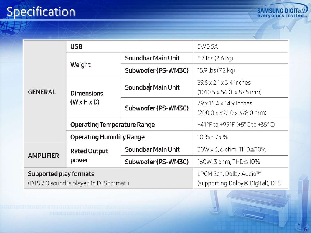
Specification6
7.
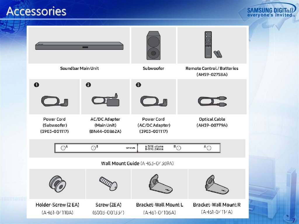
Accessories7
8.
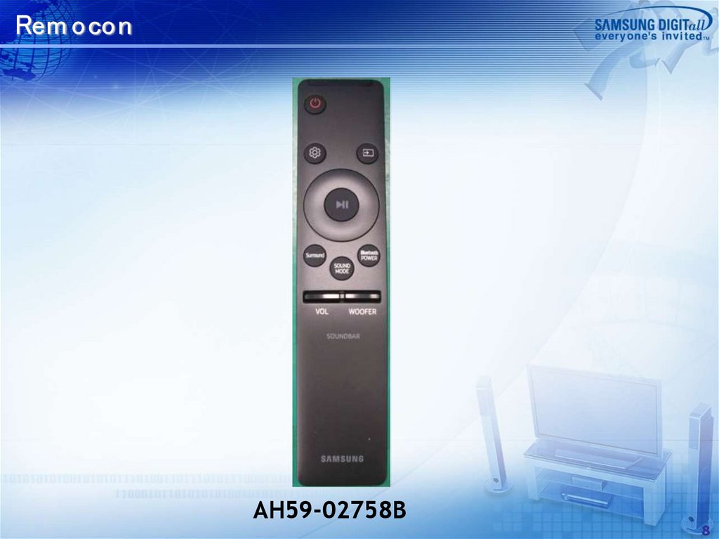
Rem oconAH59-02758B
8
9.
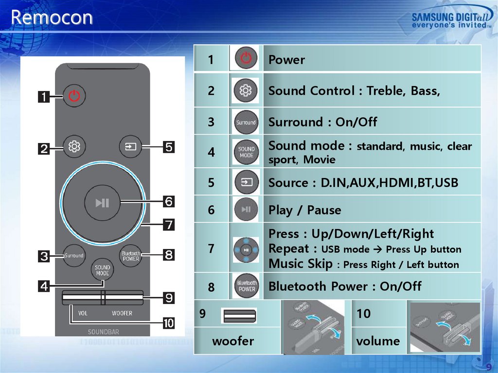
Remocon1
Power
2
Sound Control : Treble, Bass,
3
Surround : On/Off
4
Sound mode : standard, music, clear
sport, Movie
5
Source : D.IN,AUX,HDMI,BT,USB
6
Play / Pause
7
Press : Up/Down/Left/Right
Repeat : USB mode Press Up button
Music Skip : Press Right / Left button
8
Bluetooth Power : On/Off
9
10
woofer
volume
9
10.
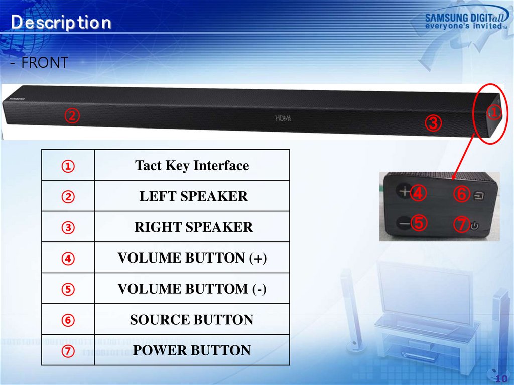
Descrip tion- FRONT
②
①
③
①
Tact Key Interface
②
LEFT SPEAKER
④
⑥
③
RIGHT SPEAKER
⑤
⑦
④
VOLUME BUTTON (+)
⑤
VOLUME BUTTOM (-)
⑥
SOURCE BUTTON
⑦
POWER BUTTON
10
11.
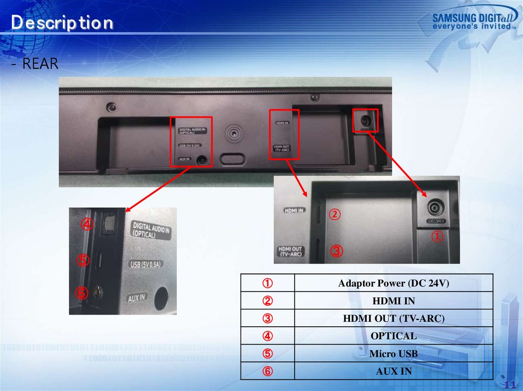
Descrip tion- REAR
②
④
①
③
⑤
⑥
①
Adaptor Power (DC 24V)
②
HDMI IN
③
HDMI OUT (TV-ARC)
④
OPTICAL
⑤
Micro USB
⑥
AUX IN
11
12.
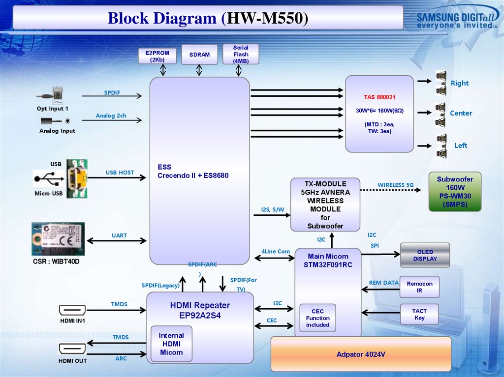
Block Diagram (HW-M550)E2PROM
(2Kb)
SDRAM
Serial
Flash
(4MB)
Right
SPDIF
Opt Input 1
TAS 880021
30W*6= 180W(6Ω)
Analog 2ch
Center
(MTD : 3ea,
TW: 3ea)
Analog Input
Left
USB
USB HOST
ESS
Crecendo II + ES8680
Micro USB
I2S, S/W
UART
CSR : WIBT40D
SPDIF(ARC
)
SPDIF(Legacy)
TMDS
HDMI IN1
TMDS
HDMI OUT
ARC
HDMI Repeater
EP92A2S4
Internal
HDMI
Micom
SPI
OLED
DISPLAY
Main Micom
STM32F091RC
SPDIF(For
REM DATA
TV)
Remocon
IR
I2C
CEC
Subwoofer
160W
PS-WM30
(SMPS)
I2C
I2C
4Line Com
WIRELESS 5G
TX-MODULE
5GHz AVNERA
WIRELESS
MODULE
for
Subwoofer
TACT
Key
CEC
Function
included
Adpator 4024V
13.
Wiring Diagram13
14.
MAIN PCB TOPCN8
IC6003
CN6002
OPJACK1
CN6
CN6001
AUX1
REF. NAME
CN8
OPJACK1
CN6
AUX1
CN6001
CN6002
PIN
14P
3P
5P
7P
19P
19P
CON. ASS'Y
OLED
USB
-
FUNCTION
OLED DISPLAY Signal
OPTICAL IN
USB Play or Update
AUX IN
HDMI OUT (TV-ARC)
HDMI IN
REF. NAME
IC6003
PIN
128P
IC
EP92A2S4_V46
FUNCTION
HDMI REPEAT IC
14
15.
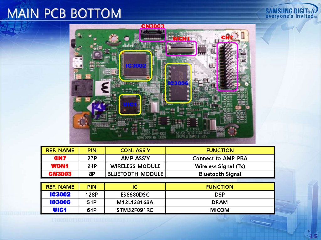
MAIN PCB BOTTOMCN3003
WCN1
CN7
IC3002
IC3006
UIC1
REF. NAME
CN7
WCN1
CN3003
PIN
27P
24P
8P
CON. ASS'Y
AMP ASS’Y
WIRELESS MODULE
BLUETOOTH MODULE
FUNCTION
Connect to AMP PBA
Wireless Signal (Tx)
Bluetooth Signal
REF. NAME
IC3002
IC3006
UIC1
PIN
128P
54P
64P
IC
ES8680DSC
M12L128168A
STM32F091RC
FUNCTION
DSP
DRAM
MICOM
15
16.
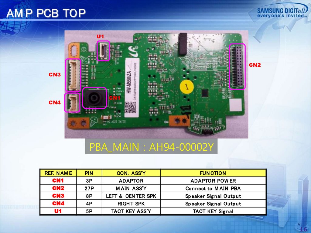
AM P PCB TOPU1
CN2
CN3
CN1
CN4
PBA_MAIN : AH94-00002Y
REF. N AM E
CN1
CN2
CN3
CN4
U1
PIN
3P
27P
8P
4P
5P
CON . ASS'Y
ADAPTOR
M AIN ASS’Y
LEFT & CEN TER SPK
RIGH T SPK
TACT KEY ASS’Y
FUN CTION
ADAPTOR POW ER
Co n n ect to M AIN PBA
Sp eaker Sig n al Ou tp u t
Sp eaker Sig n al Ou tp u t
TACT KEY Sig n al
16
17.
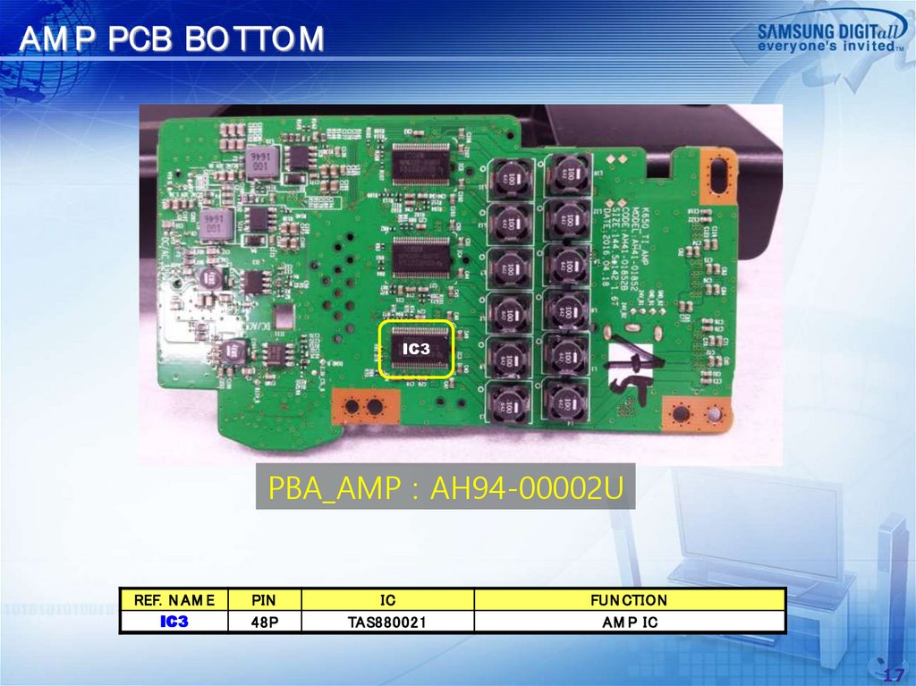
AM P PCB BOTTOMIC3
PBA_AMP : AH94-00002U
REF. N AM E
IC3
PIN
48P
IC
TAS880021
FUN CTION
AM P IC
17
18.
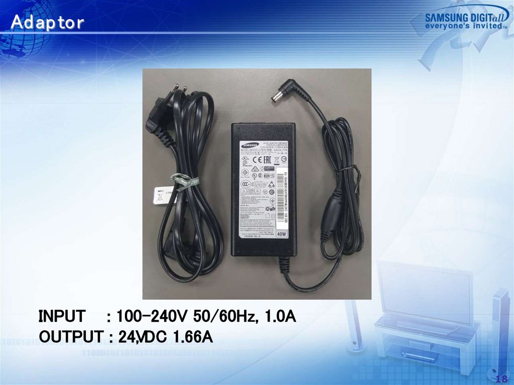
Ad ap torINPUT : 100-240V 50/60Hz, 1.0A
OUTPUT : 24V
, DC 1.66A
18
19.
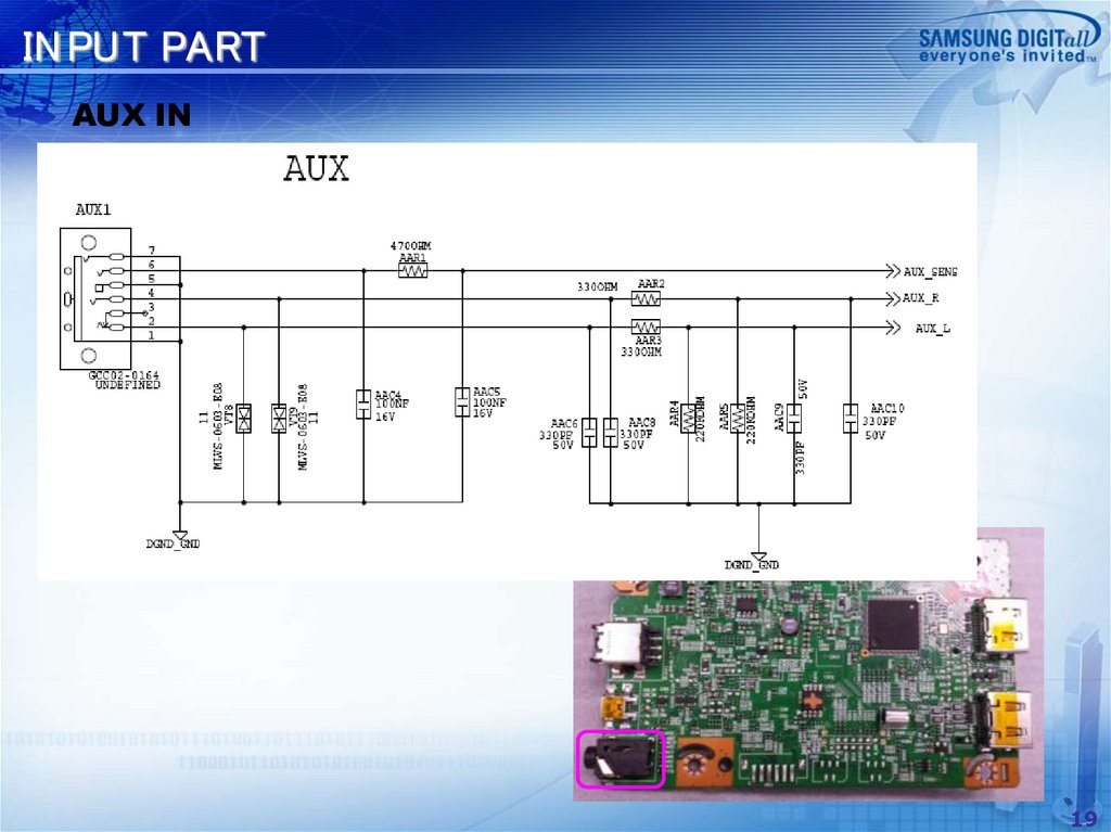
IN PUT PARTAUX IN
19
20.
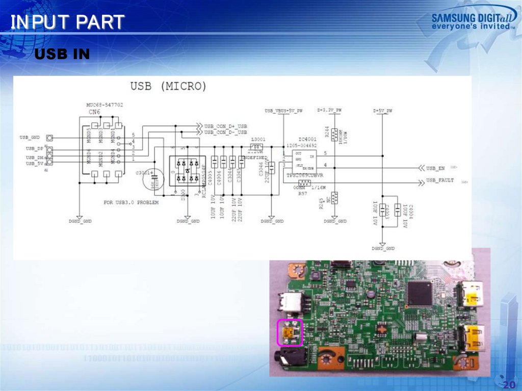
IN PUT PARTUSB IN
20
21.
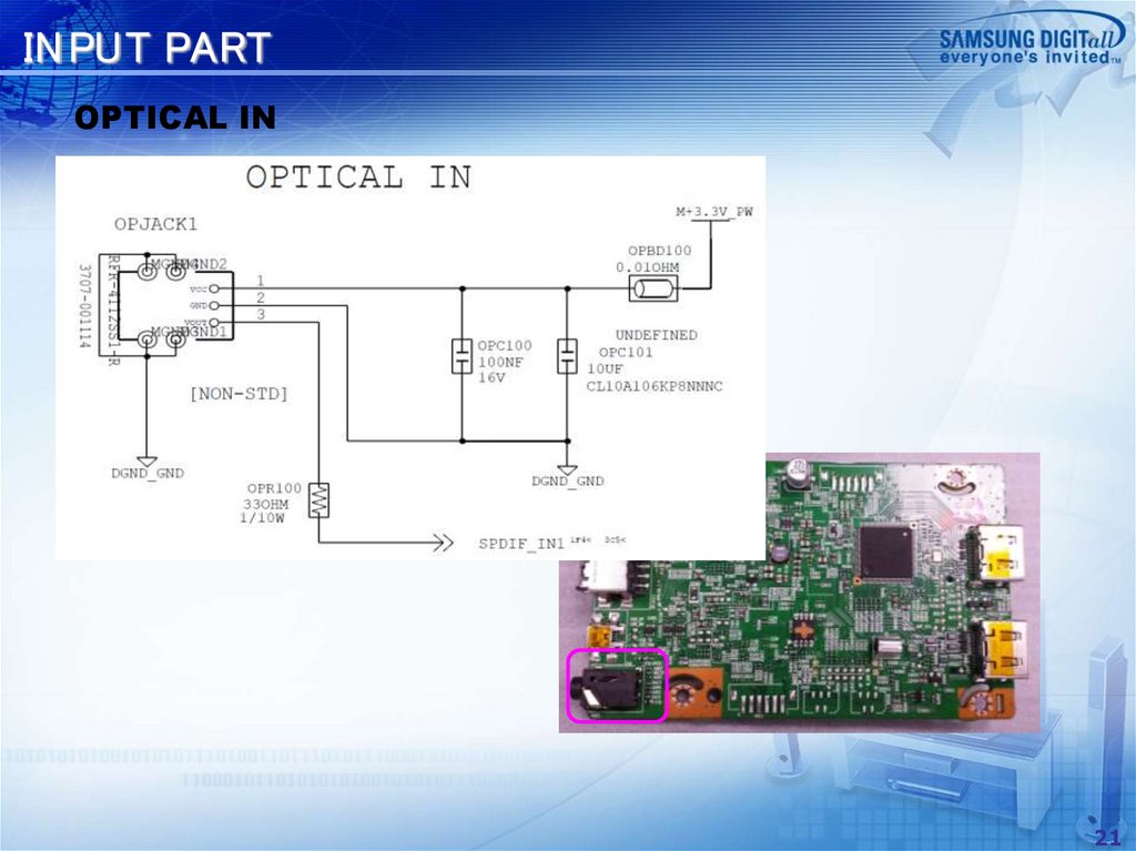
IN PUT PARTOPTICAL IN
21
22.
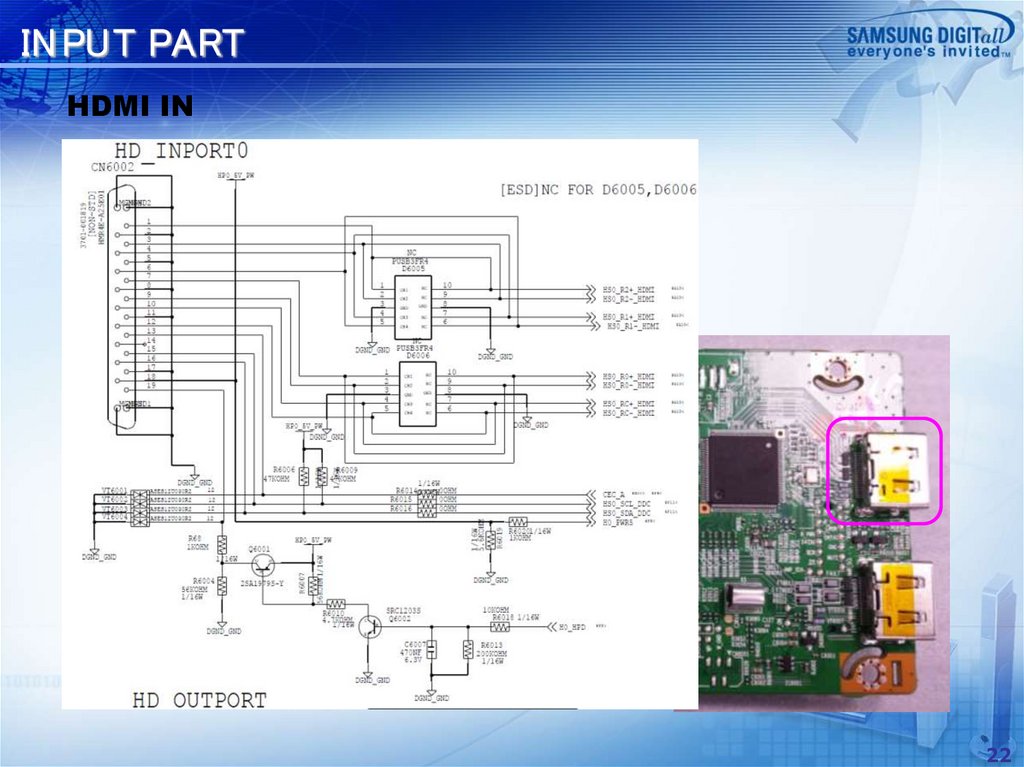
IN PUT PARTHDMI IN
22
23.
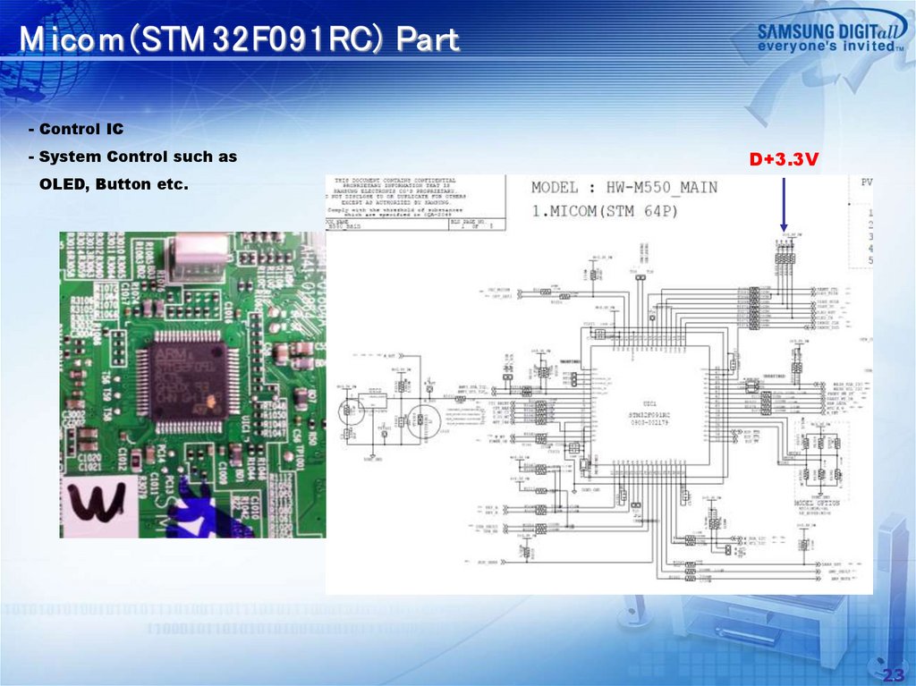
M icom (STM 32F091RC) Part- Control IC
- System Control such as
D+3.3V
OLED, Button etc.
23
24.
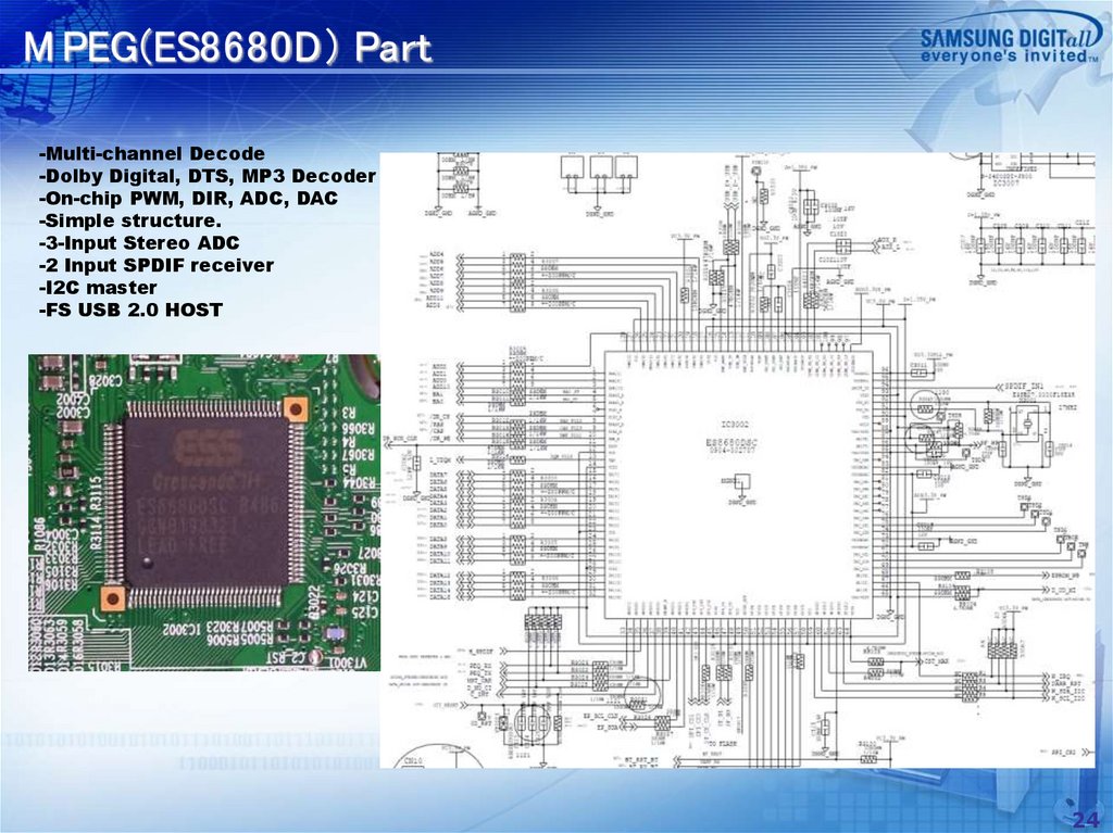
M PEG(ES8680D) Part-Multi-channel Decode
-Dolby Digital, DTS, MP3 Decoder
-On-chip PWM, DIR, ADC, DAC
-Simple structure.
-3-Input Stereo ADC
-2 Input SPDIF receiver
-I2C master
-FS USB 2.0 HOST
24
25.
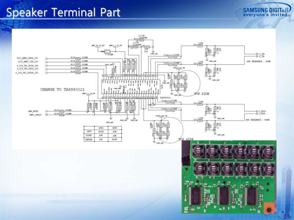
Speaker Terminal Part25
26.
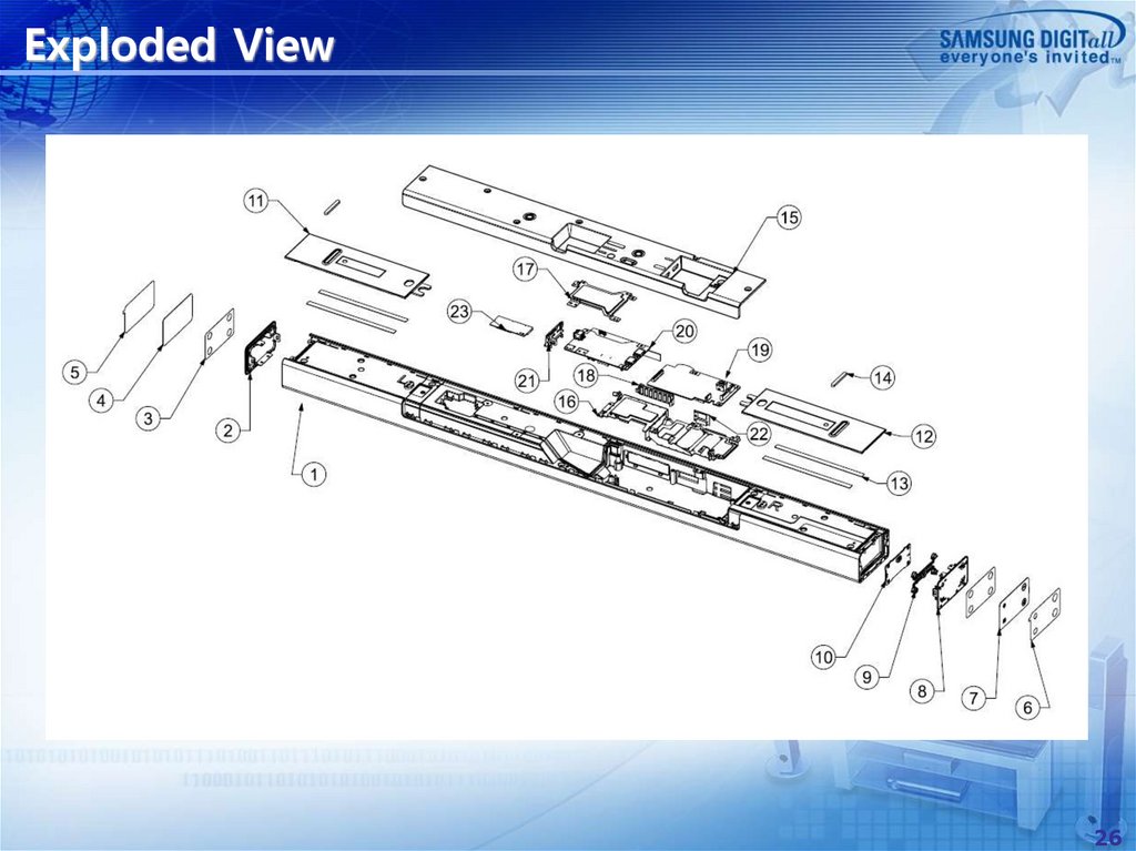
Exploded View26
27.
Service Parts order information(updatedNo
1
Part Name
ASSY COVER P-TOP
2
COVER-DECORATION RIGHT
3
4
TAPE DOUBLE SIDE
COVER-RIGHT
5
6
7
SHEET-PROTECTION RIGHT
SHEET-PROTECTION LEFT
COVER-LEFT
8
COVER-DECORATION LEFT
9
10
11
BUTTON-FUNCTION
PCB-FUNCTION
COVER-DECORATION BOTTOM LEFT
12
COVER-DECORATION BOTTOM RIGHT
13
14
15
TAPE DOUBLE SIDE
FOOT-RUBBER FRONT
COVER-PCB
16
17
18
19
20
21
BRACKET-PCB
SHIELD-PCB
HOLDER-DISPLAY
PCB-AMP
PCB-MAIN
COVER-TERMINAL
22
23
PCB-BT
PCB-WIRELESS
Part Code
AH96-04157C
AH63-04375B
AH63-04329A
AH63-04329B
AH02-00100A
AH63-04365A
AH63-04367A
AH63-04371A
AH63-04368A
AH63-04364A
AH63-04366A
AH63-04328A
AH63-04328B
AH64-05993A
AH41-01851A
AH64-05999A
AH64-05999B
AH64-06001A
AH64-06001B
AH02-00101A
AH67-00750A
AH63-04331A
AH63-04331B
AH63-04331C
AH63-04331D
AH61-04108A
AH63-04308A
AH61-04104A
AH94-00002U
AH94-00002Y
AH63-04332A
AH63-04332B
AH96-02298A
AH59-02746A
Spec.
BLACK(HW-K550/650)
SILVER(HW-K551/651)
BLACK(HW-K550/650)
SILVER(HW-K551/651)
BLACK(HW-K550/650)
SILVER(HW-K551/651)
BLACK(HW-K550/650)
SILVER(HW-K551/651)
BLACK(HW-K550/650)
SILVER(HW-K551/651)
BLACK(HW-K550/650)
SILVER(HW-K551/651)
BLACK(HW-K550/650)
SILVER(HW-K551/651)
BLACK(HW-K550)
SILVER(HW-K551)
BLACK(HW-K650)
SILVER(HW-K651)
BLACK(HW-K550/650)
SILVER(HW-K551/651)
27
28.
Disassemble1) Loosen 7 screws at the Bottom Cover. BH,M3,L10,ZPC(BLK)
2) Pull the Bottom Cover Slowly.
28
29.
Disassemble1) Unplug 3 Connectors on the AMP Assy
2) Loosen 4 screws (red circle) on the MAIN & AMP Assy. BH,M3,L10,ZPC(BLK)
3) Pull the MAIN & AMP Assy Slowly
29
30.
Disassemble1) Loosen 2 screws (red circle) on the MAIN & AMP Assy.
BH,M3,L10,ZPC(WHT)
2) Unplug 1 Connector on the MAIN Assy
3) Remove the Iron plate
30
31.
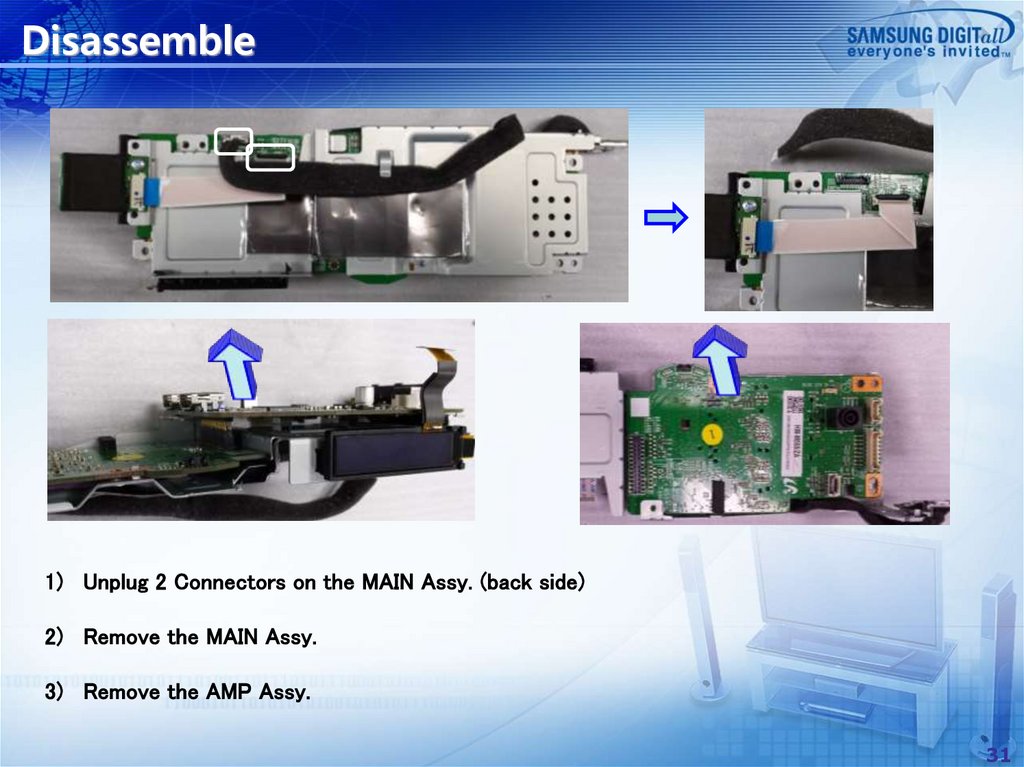
Disassemble1) Unplug 2 Connectors on the MAIN Assy. (back side)
2) Remove the MAIN Assy.
3) Remove the AMP Assy.
31
32.
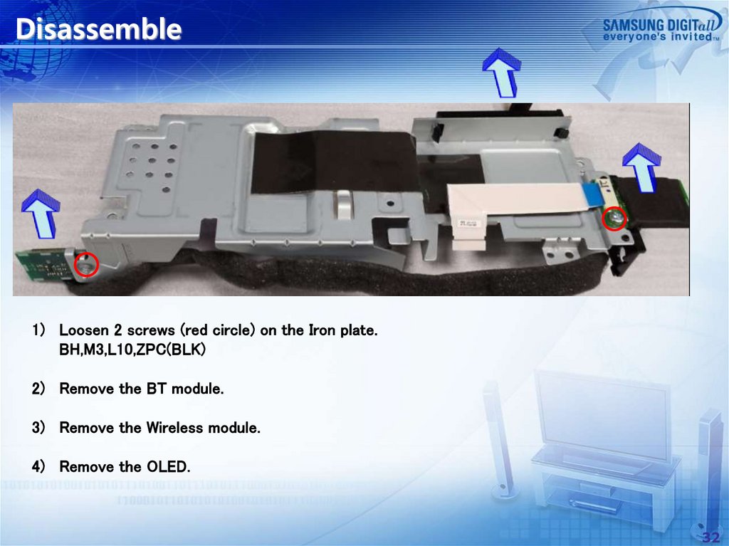
Disassemble1) Loosen 2 screws (red circle) on the Iron plate.
BH,M3,L10,ZPC(BLK)
2) Remove the BT module.
3) Remove the Wireless module.
4) Remove the OLED.
32
33.
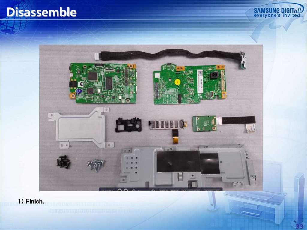
Disassemble1) Finish.
33
34.
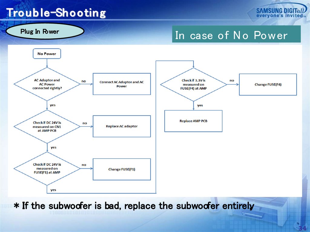
Tro u b le-Sh o o tin gPlug In Power
In case of N o Power
* If the subwoofer is bad, replace the subwoofer entirely.
34
35.
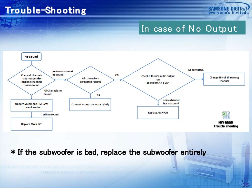
Tro u b le-Sh o o tin gIn case of N o Outp ut
* If the subwoofer is bad, replace the subwoofer entirely.
35
36.
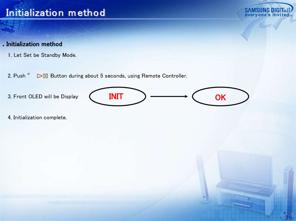
Initialization m ethod. Initialization method
1. Let Set be Standby Mode.
2. Push “
” Button during about 5 seconds, using Remote Controller.
3. Front OLED will be Display
INIT
OK
4. Initialization complete.
36
37.
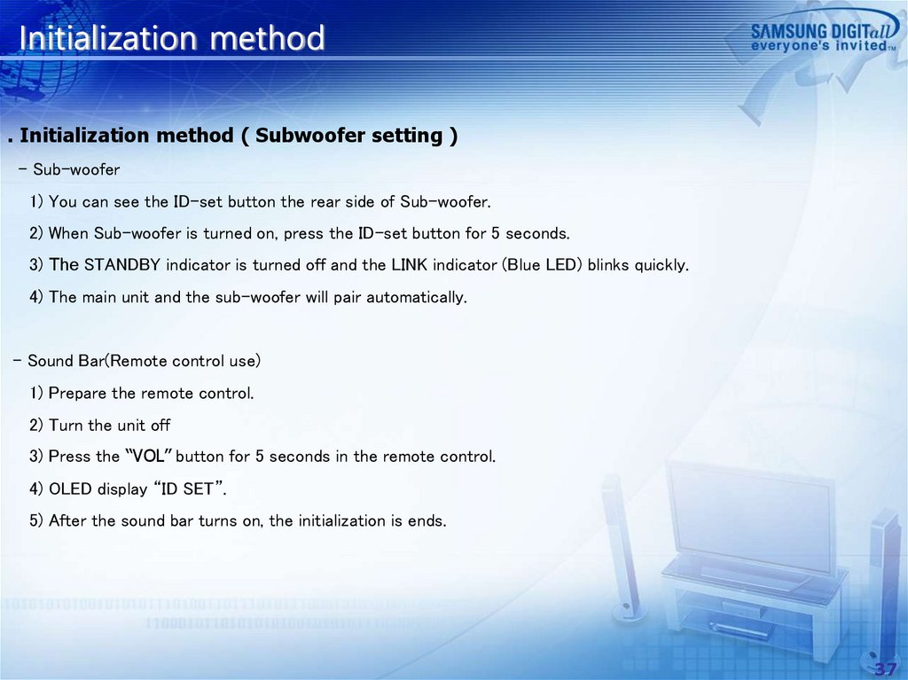
Initialization method. Initialization method ( Subwoofer setting )
- Sub-woofer
1) You can see the ID-set button the rear side of Sub-woofer.
2) When Sub-woofer is turned on, press the ID-set button for 5 seconds.
3) The STANDBY indicator is turned off and the LINK indicator (Blue LED) blinks quickly.
4) The main unit and the sub-woofer will pair automatically.
- Sound Bar(Remote control use)
1) Prepare the remote control.
2) Turn the unit off
3) Press the “VOL” button for 5 seconds in the remote control.
4) OLED display “ID SET”.
5) After the sound bar turns on, the initialization is ends.
37
38.
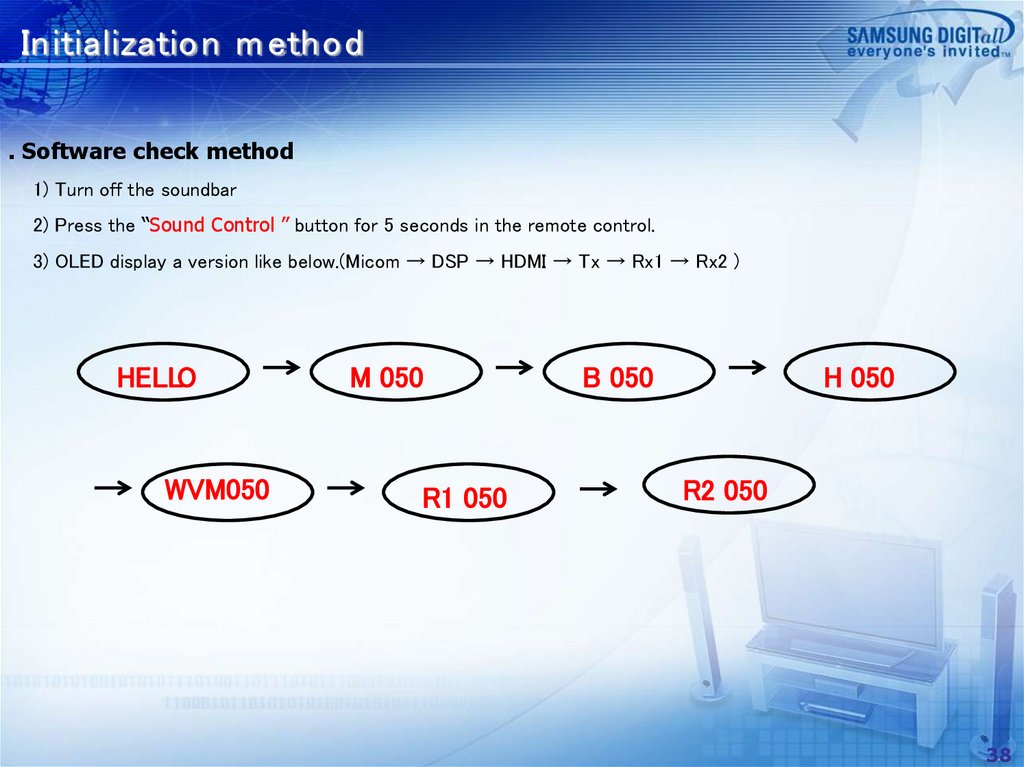
Initialization m ethod. Software check method
1) Turn off the soundbar
2) Press the “Sound Control ” button for 5 seconds in the remote control.
3) OLED display a version like below.(Micom → DSP → HDMI → Tx → Rx1 → Rx2 )
HELLO
WVM050
M 050
R1 050
B 050
H 050
R2 050
38
39.
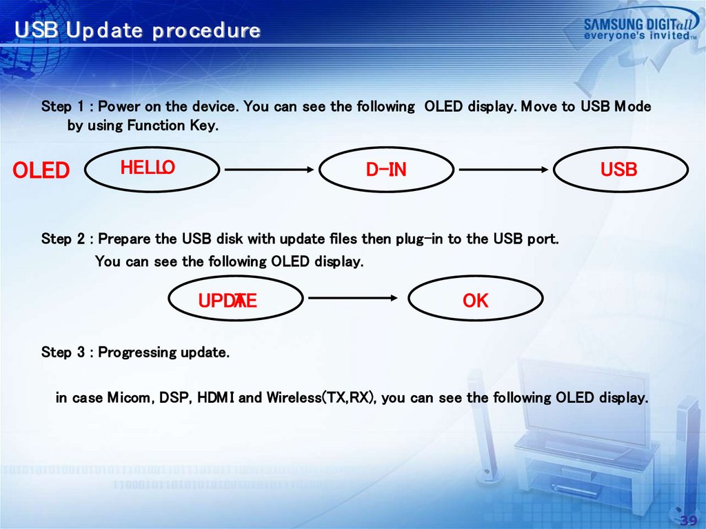
USB Up d ate p roced ureStep 1 : Power on the device. You can see the following OLED display. Move to USB M ode
by using Function Key.
OLED
HELLO
D-IN
USB
Step 2 : Prepare the USB disk with update files then plug-in to the USB port.
You can see the following OLED display.
UPDA
TE
OK
Step 3 : Progressing update.
in case Micom, DSP, HDM I and Wireless(TX,RX), you can see the following OLED display.
39
40.
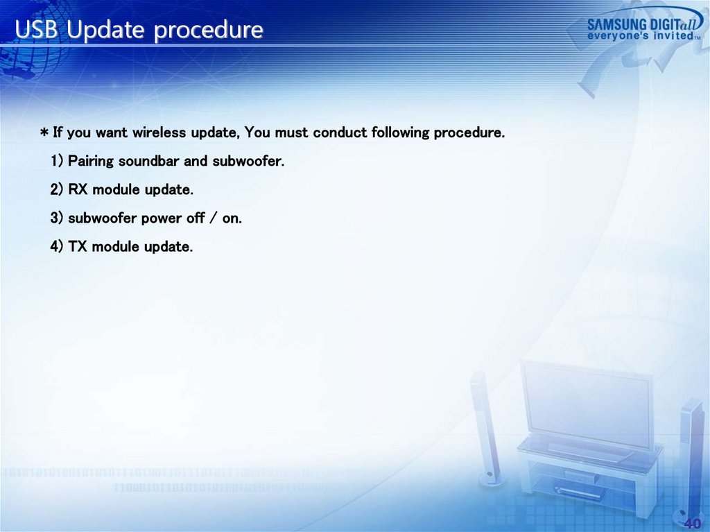
USB Update procedure* If you want wireless update, You must conduct following procedure.
1) Pairing soundbar and subwoofer.
2) RX module update.
3) subwoofer power off / on.
4) TX module update.
40
41.
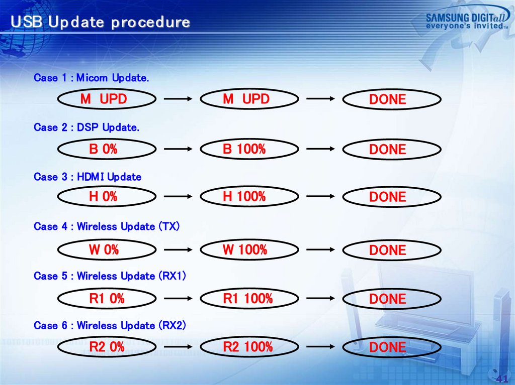
USB Up d ate p roced ureCase 1 : M icom Update.
M UPD
M UPD
DONE
B 100%
DONE
H 100%
DONE
W 100%
DONE
R1 100%
DONE
R2 100%
DONE
Case 2 : DSP Update.
B 0%
Case 3 : HDM I Update
H 0%
Case 4 : Wireless Update (TX)
W 0%
Case 5 : Wireless Update (RX1)
R1 0%
Case 6 : Wireless Update (RX2)
R2 0%
41
42.
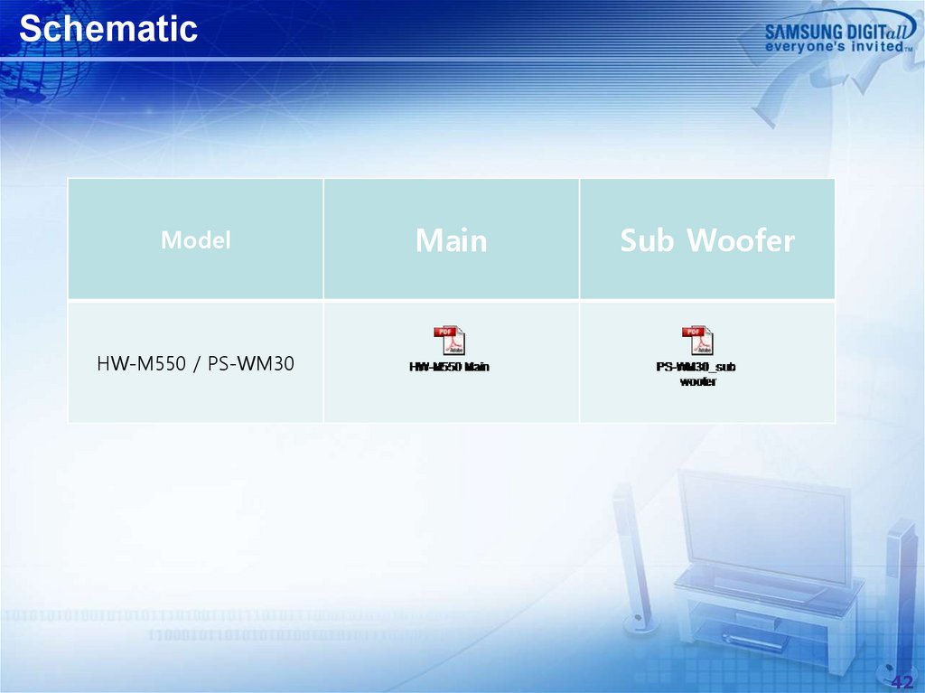
SchematicModel
Main
Sub Woofer
HW-M550 / PS-WM30
42