


 electronics
Similar presentations:


MU6100. Training Manual
1.
2.
Table of ContentsTable of Contents
1. Product Introduction
2. Key Features & Operation
3. Front/Rear View
4. Repair Preparations
5. Layout
6. Wiring Diagram
7. Circuit Description
8. Troubleshooting
9. Factory Mode
10. Disassembly & Reassembly
3.
4.
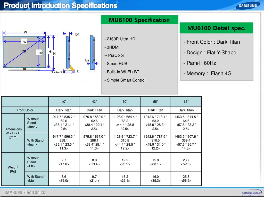
MU6100 SpecificationMU6100 Detail spec.
W
D1
- 2160P Ultra HD
W2
- Front Color : Dark Titan
- 3HDMI
D3
H2
H1
H
- Design : Flat Y-Shape
-- PurColor
D2
*Rubber 포함
D
- Smart HUB
- Panel : 60Hz
- Built–in Wi-Fi / BT
- Memory : Flash 4G
- Simple Smart Control
40”
43”
50”
55”
65”
Dark Titan
Dark Titan
Dark Titan
Dark Titan
Dark Titan
Without
Stand
<Inch>
917.7 * 535.7 *
62.6
<36.1 * 21.1 *
2.5>
975.8 * 569.0 *
62.6
<38.4 * 22.4 *
2.5>
1128.9 * 654.4 *
63.2
<44.4 * 25.8
*2.5>
1242.6 * 718.4 *
63.2
<48.9 * 28.3 *
2.5>
1463.5 * 844.5 *
64.6
<57.6 * 33.2 *
2.5>
With Stand
<Inch>
917.7 * 596.5 *
288.1
<36.1 * 23.5 *
11.3>
975.8 * 637.0 *
288.1
<38.4* 25.1 *
11.3>
1128.9 * 723.7 *
310.5
<44.4 * 28.5 *
12.2>
1242.6 * 787.5 *
310.5
<48.9 * 31.0 *
12.2>
1463.5 * 907.6 *
369.4
<57.6 * 35.7 *
14.5>
Without
Stand
<Lb>
7.7
<17.0>
8.8
<19.4>
12.2
<26.9>
15.0
<33.1>
23.7
<52.2>
With Stand
<Lb>
8.6
<19.0>
9.7
<21.4>
13.2
<29.1>
16.0
<35.3>
25.8
<56.9>
Front Color
Dimensions
WxDxH
[(mm]
Weight
[Kg]
5.
SpecificationMU6100
CPU
4 X CA72 @1.7GHz
DDR
LPDDR4 64bit @1.6GHz, 2GB
Flash
4GB ( eMMC5.0)
HDMI
USB
3 INPUT, HDMI 2.0
2 INPUT, USB 2.0
Voice Recognition
O
Camera
X
Eco Sensor/IR/LED , BT/WIFI
Sound output
Screen Mirroring
Built-in bottom Frame
20W(Left 10W Right 10W)
YES (TV to Mobile, Mobile to TV)
6.
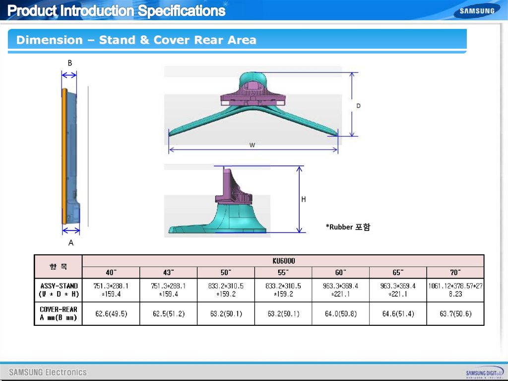
Dimension – Stand & Cover Rear AreaB
A
7.
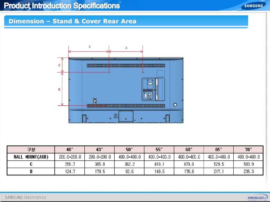
Dimension – Stand & Cover Rear Area8.
9.
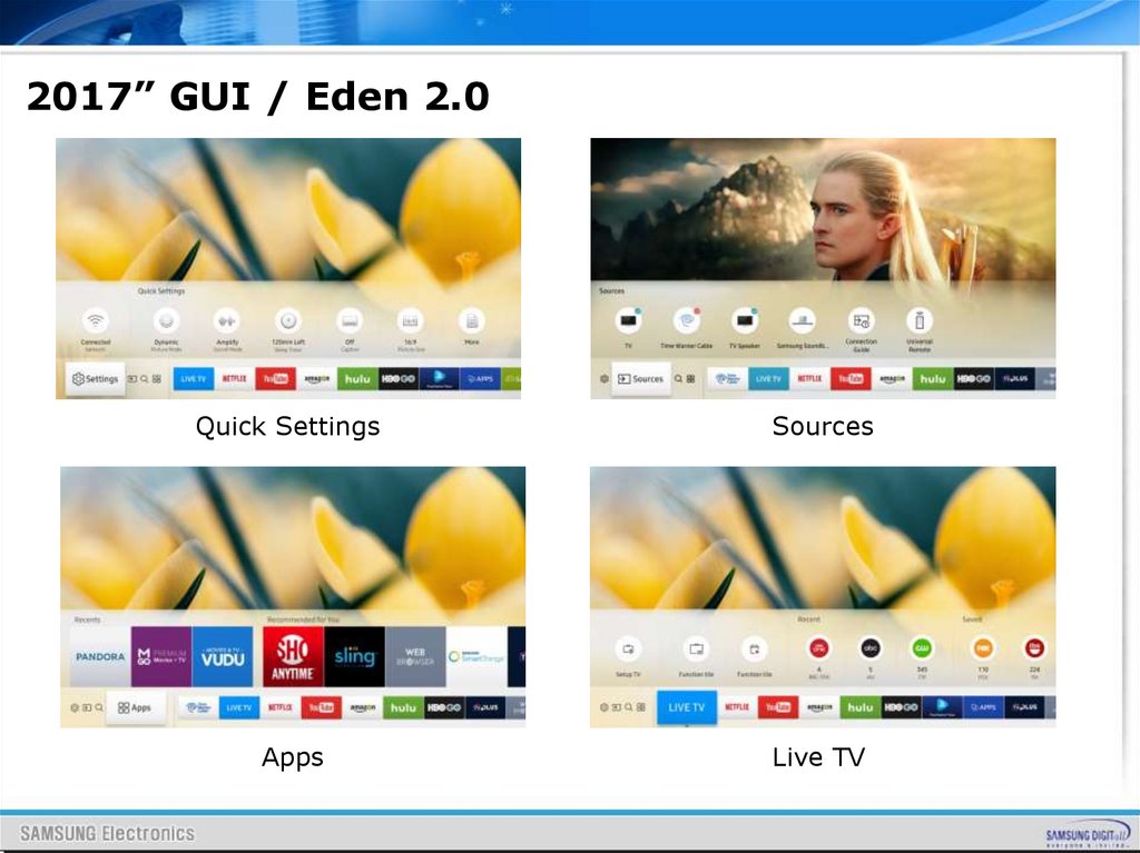
2017” GUI / Eden 2.0Quick Settings
Sources
Apps
Live TV
10.
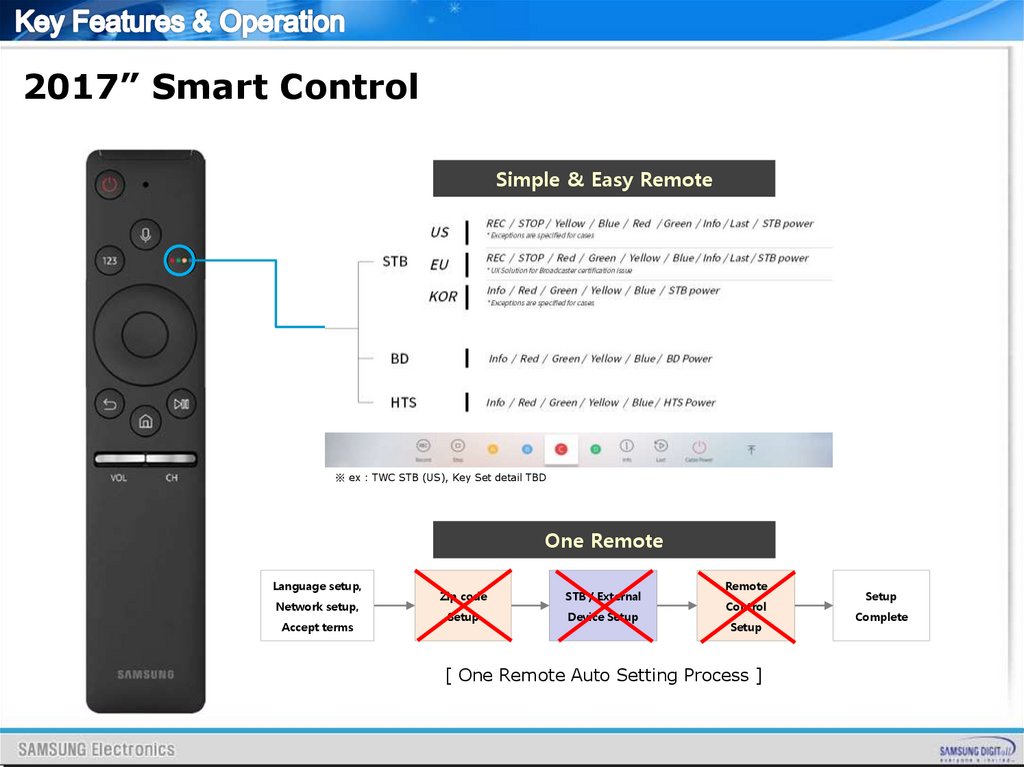
2017” Smart ControlSimple & Easy Remote
※ ex : TWC STB (US), Key Set detail TBD
One Remote
Language setup,
Network setup,
Accept terms
Zip code
STB / External
Setup
Device Setup
Remote
Control
Setup
[ One Remote Auto Setting Process ]
Setup
Complete
11.
2017” Smart Control12.
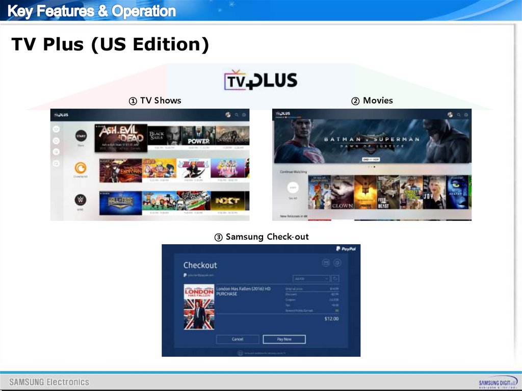
TV Plus (US Edition)① TV Shows
② Movies
③ Samsung Check-out
13.
14.
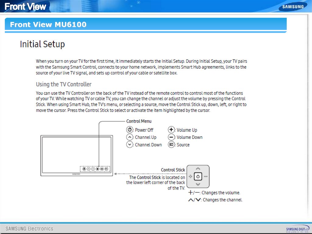
Front View MU610015.
16.
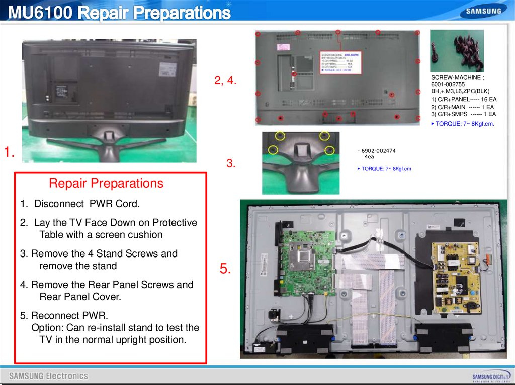
MU6100SCREW-MACHINE ;
6001-002755
BH,+,M3,L6,ZPC(BLK)
1) C/R+PANEL----- 16 EA
2) C/R+MAIN ------ 1 EA
3) C/R+SMPS ------ 1 EA
2, 4.
▶ TORQUE: 7~ 8Kgf.cm.
1.
3.
Repair Preparations
1. Disconnect PWR Cord.
2. Lay the TV Face Down on Protective
Table with a screen cushion
3. Remove the 4 Stand Screws and
remove the stand
4. Remove the Rear Panel Screws and
Rear Panel Cover.
5. Reconnect PWR.
Option: Can re-install stand to test the
TV in the normal upright position.
5.
- 6902-002474
4ea
▶ TORQUE: 7~ 8Kgf.cm
17.
MU6100Removing SMPS board
Removing Main board
Remove 2 Cables and 4 Screws on Power Connector
- Use both hands to hold the 'TV Board' and slide the
board to the right to release the board.
Then carefully remove the 'TV Board'.
18.
19.
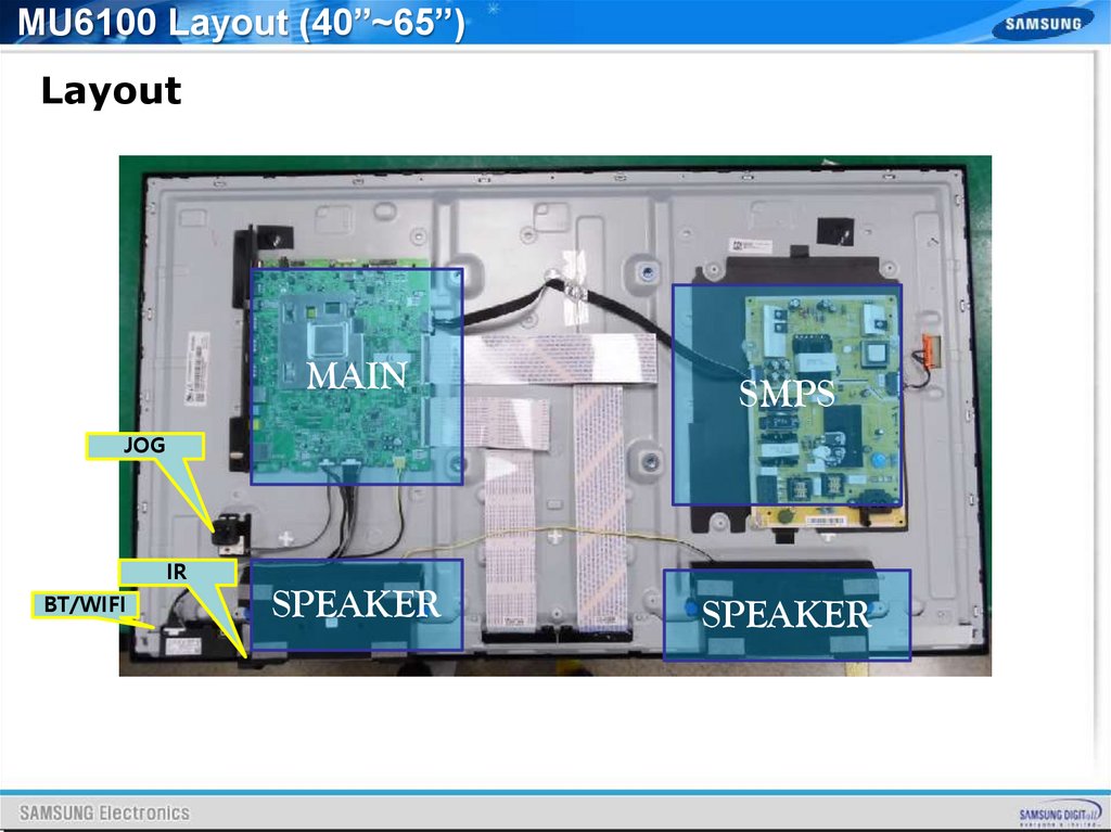
MU6100 Layout (40”~65”)Layout
MAIN
SMPS
SPEAKER
SPEAKER
JOG
IR
BT/WIFI
20.
21.
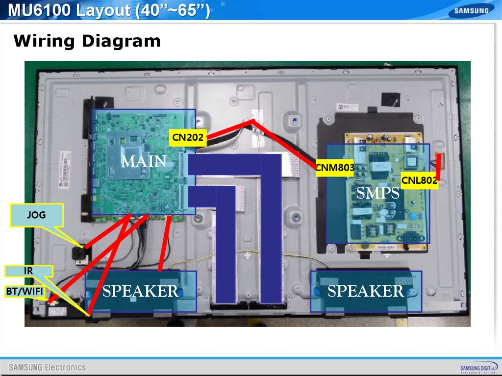
MU6100 Layout (40”~65”)Wiring Diagram
CN202
MAIN
CNM803
SMPS
CNL802
JOG
IR
BT/WIFI
SPEAKER
SPEAKER
22.
23.
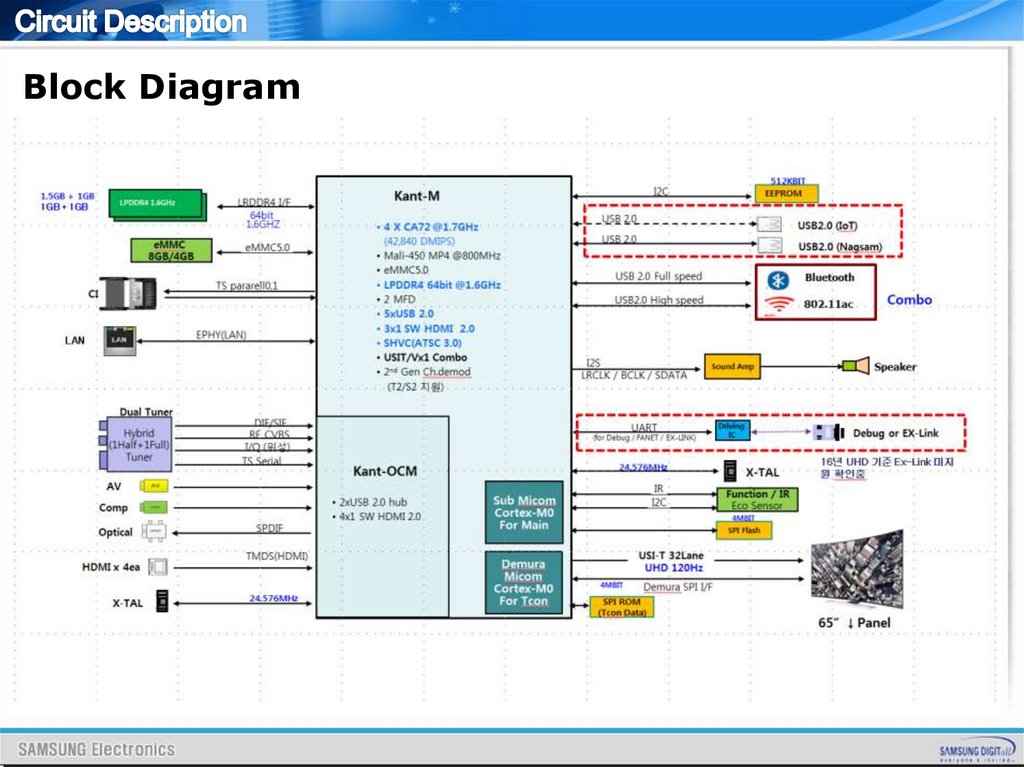
Block Diagram24.
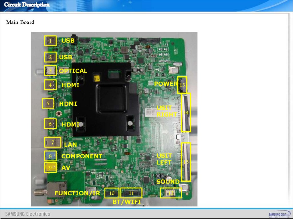
Main Board1
USB
2
USB
3
OPTICAL
4
HDMI
5
HDMI
6
HDMI
7
LAN
8
COMPONENT
9
AV
POWER 15
USIT
RIGHT
14
USIT
LEFT
13
SOUND
FUNCTION/IR
10
11
BT/WIFI
12
25.
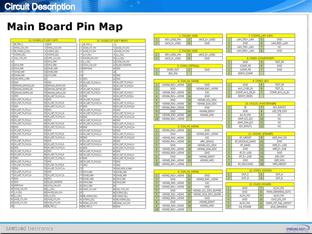
Main Board Pin MapPower
Arm
Jtag
Tcon
Flash
Demura
Micom
Aging&Mura
Flash
Dimming
USIT Left
USB
Ex-Link
LAN
USIT Right
One
Connect
Function/IR
BT/Wifi Sound
26.
27.
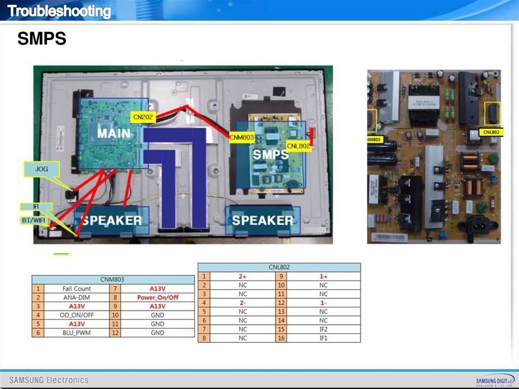
SMPSSMPS
Fuse
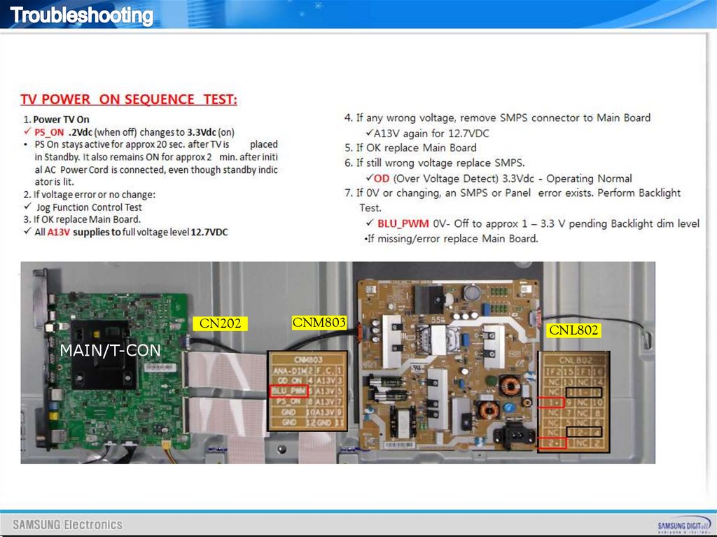
28.
SMPS29.
MPSCN202
MAIN/T-CON
CNM803
CNL802
30.
31.
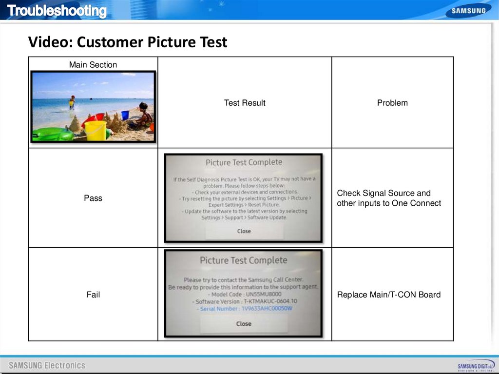
Video: Customer Picture TestMain Section
Test Result
Problem
Pass
Check Signal Source and
other inputs to One Connect
Fail
Replace Main/T-CON Board
32.
VideoENTER: Factory mode -> SVC -> Test Pattern
Scaler Pattern
1.
US Post Pattern
Main Board
Kant-M
2.
FRC Pre Test Pattern
FRC
T-CON
4.
3.
FRC Post Test Pattern
SoC TCON Test
Pattern
Check Test Patterns
1. Verify “Scaler Pattern” and
“US Post Pattern”
2. Verify “FRC Pre Test Pattern”
3.Verify “FRC Post Test Pattern”
4. Verify “SoC TCON Test Pattern”
33.
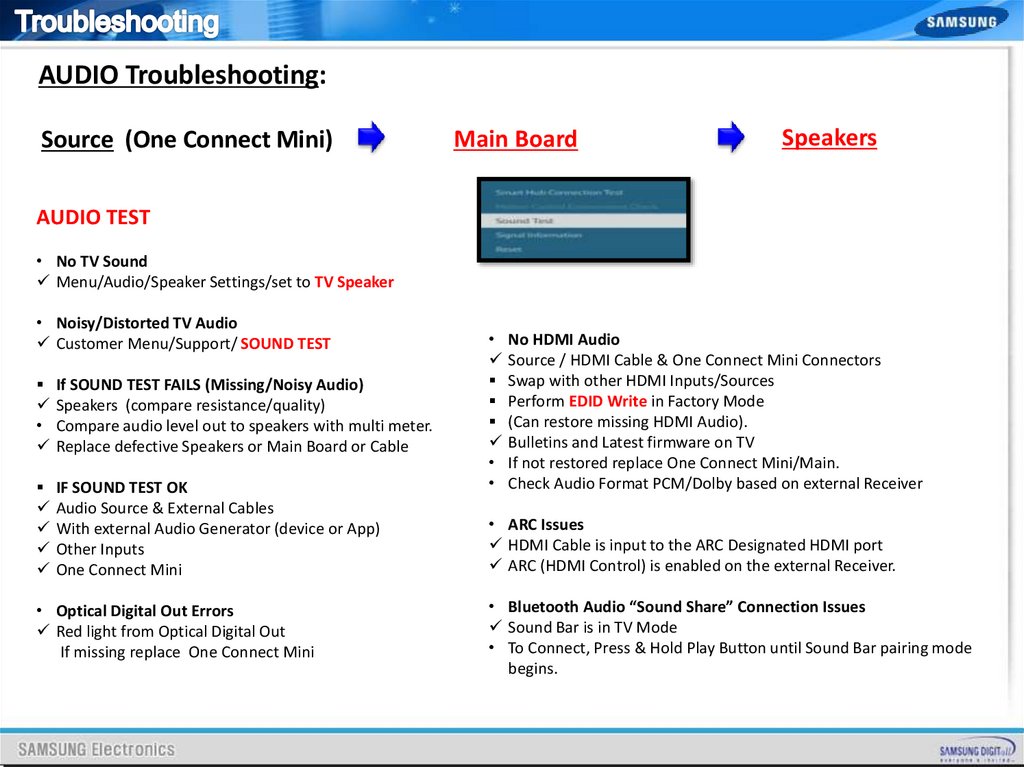
AUDIO Troubleshooting:Source (One Connect Mini)
Main Board
Speakers
AUDIO TEST
• No TV Sound
Menu/Audio/Speaker Settings/set to TV Speaker
• Noisy/Distorted TV Audio
Customer Menu/Support/ SOUND TEST
If SOUND TEST FAILS (Missing/Noisy Audio)
Speakers (compare resistance/quality)
• Compare audio level out to speakers with multi meter.
Replace defective Speakers or Main Board or Cable
IF SOUND TEST OK
Audio Source & External Cables
With external Audio Generator (device or App)
Other Inputs
One Connect Mini
• Optical Digital Out Errors
Red light from Optical Digital Out
If missing replace One Connect Mini
• No HDMI Audio
Source / HDMI Cable & One Connect Mini Connectors
Swap with other HDMI Inputs/Sources
Perform EDID Write in Factory Mode
(Can restore missing HDMI Audio).
Bulletins and Latest firmware on TV
• If not restored replace One Connect Mini/Main.
• Check Audio Format PCM/Dolby based on external Receiver
• ARC Issues
HDMI Cable is input to the ARC Designated HDMI port
ARC (HDMI Control) is enabled on the external Receiver.
• Bluetooth Audio “Sound Share” Connection Issues
Sound Bar is in TV Mode
• To Connect, Press & Hold Play Button until Sound Bar pairing mode
begins.
34.
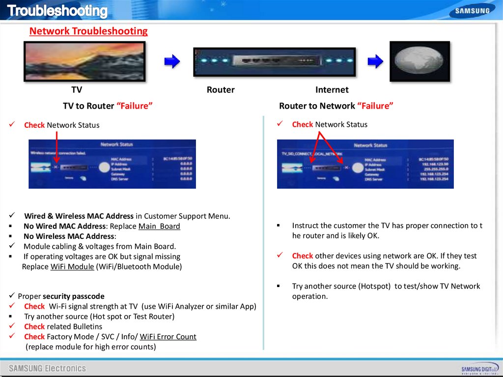
Network TroubleshootingTV
Router
TV to Router “Failure”
Check Network Status
Wired & Wireless MAC Address in Customer Support Menu.
No Wired MAC Address: Replace Main Board
No Wireless MAC Address:
Module cabling & voltages from Main Board.
If operating voltages are OK but signal missing
Replace WiFi Module (WiFi/Bluetooth Module)
Proper security passcode
Check Wi-Fi signal strength at TV (use WiFi Analyzer or similar App)
Try another source (Hot spot or Test Router)
Check related Bulletins
Check Factory Mode / SVC / Info/ WiFi Error Count
(replace module for high error counts)
Internet
Router to Network “Failure”
Check Network Status
Instruct the customer the TV has proper connection to t
he router and is likely OK.
Check other devices using network are OK. If they test
OK this does not mean the TV should be working.
Try another source (Hotspot) to test/show TV Network
operation.
35.
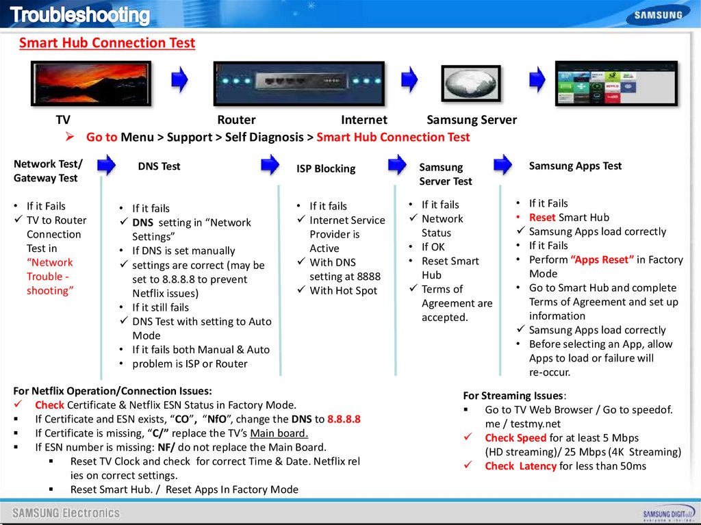
Smart Hub Connection TestTV
Router
Internet
Samsung Server
Go to Menu > Support > Self Diagnosis > Smart Hub Connection Test
Network Test/
Gateway Test
• If it Fails
TV to Router
Connection
Test in
“Network
Trouble shooting”
DNS Test
• If it fails
DNS setting in “Network
Settings”
• If DNS is set manually
settings are correct (may be
set to 8.8.8.8 to prevent
Netflix issues)
• If it still fails
DNS Test with setting to Auto
Mode
• If it fails both Manual & Auto
• problem is ISP or Router
ISP Blocking
• If it fails
Internet Service
Provider is
Active
With DNS
setting at 8888
With Hot Spot
For Netflix Operation/Connection Issues:
Check Certificate & Netflix ESN Status in Factory Mode.
If Certificate and ESN exists, “CO”, “NfO”, change the DNS to 8.8.8.8
If Certificate is missing, “C/” replace the TV’s Main board.
If ESN number is missing: NF/ do not replace the Main Board.
Reset TV Clock and check for correct Time & Date. Netflix rel
ies on correct settings.
Reset Smart Hub. / Reset Apps In Factory Mode
Samsung
Server Test
• If it fails
Network
Status
• If OK
• Reset Smart
Hub
Terms of
Agreement are
accepted.
Samsung Apps Test
• If it Fails
• Reset Smart Hub
Samsung Apps load correctly
• If it Fails
• Perform “Apps Reset” in Factory
Mode
• Go to Smart Hub and complete
Terms of Agreement and set up
information
Samsung Apps load correctly
• Before selecting an App, allow
Apps to load or failure will
re-occur.
For Streaming Issues:
Go to TV Web Browser / Go to speedof.
me / testmy.net
Check Speed for at least 5 Mbps
(HD streaming)/ 25 Mbps (4K Streaming)
Check Latency for less than 50ms
36.
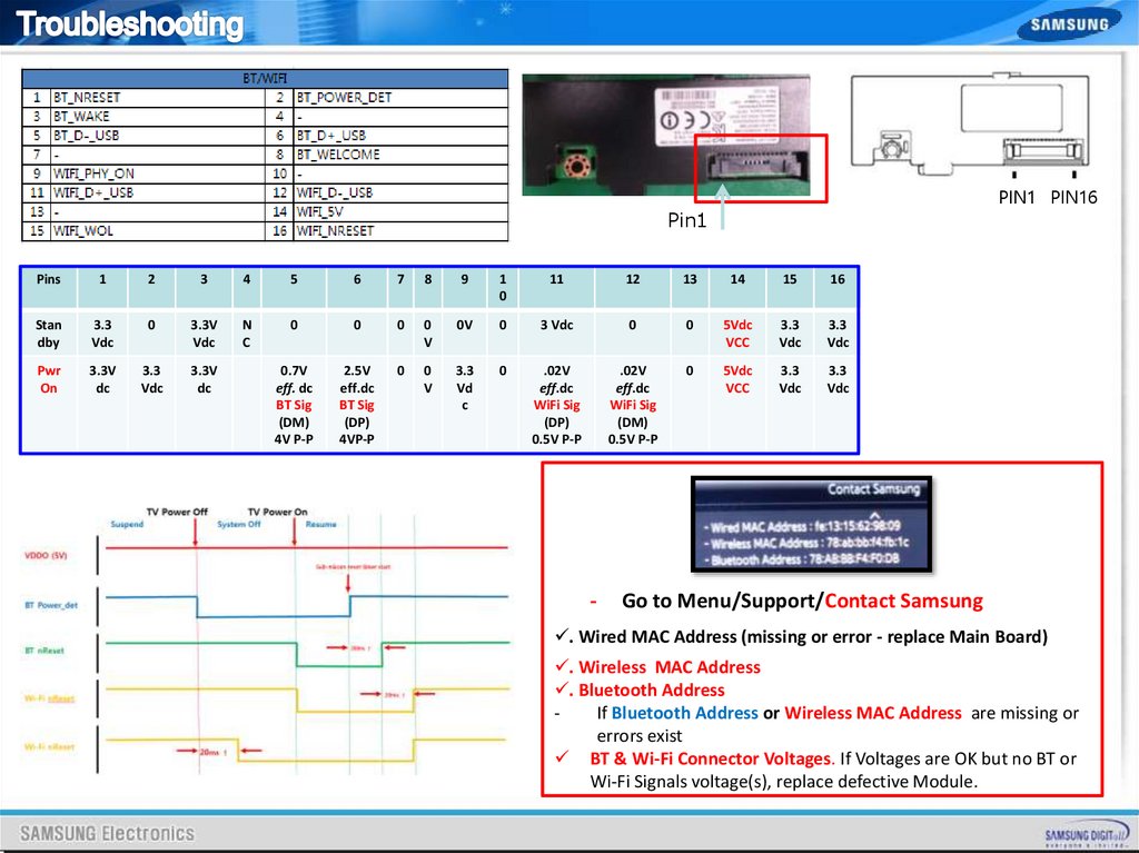
PIN1 PIN16Pin1
Pins
1
2
3
4
5
6
7
8
9
1
0
11
12
13
14
15
16
Stan
dby
3.3
Vdc
0
3.3V
Vdc
N
C
0
0
0
0
V
0V
0
3 Vdc
0
0
5Vdc
VCC
3.3
Vdc
3.3
Vdc
Pwr
On
3.3V
dc
3.3
Vdc
3.3V
dc
0.7V
eff. dc
BT Sig
(DM)
4V P-P
2.5V
eff.dc
BT Sig
(DP)
4VP-P
0
0
V
3.3
Vd
c
0
.02V
eff.dc
WiFi Sig
(DP)
0.5V P-P
.02V
eff.dc
WiFi Sig
(DM)
0.5V P-P
0
5Vdc
VCC
3.3
Vdc
3.3
Vdc
-
Go to Menu/Support/Contact Samsung
. Wired MAC Address (missing or error - replace Main Board)
. Wireless MAC Address
. Bluetooth Address
If Bluetooth Address or Wireless MAC Address are missing or
errors exist
BT & Wi-Fi Connector Voltages. If Voltages are OK but no BT or
Wi-Fi Signals voltage(s), replace defective Module.
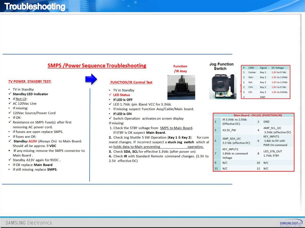
37.
38.
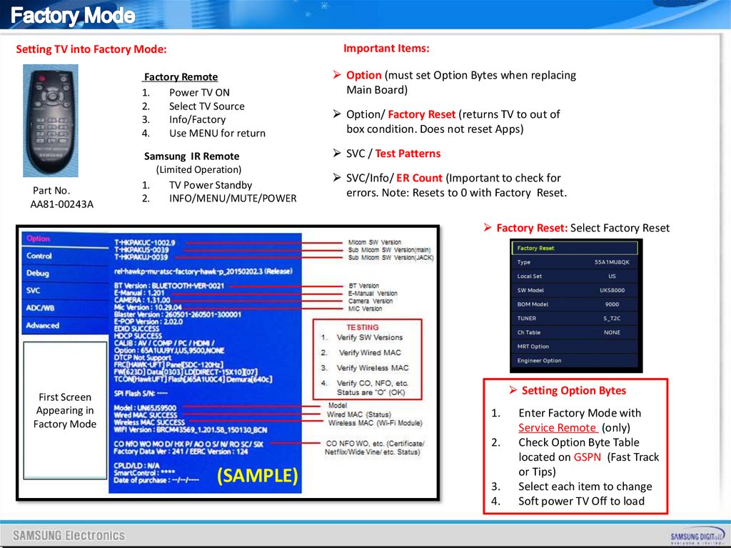
Important Items:Setting TV into Factory Mode:
Part No.
AA81-00243A
Factory Remote
1.
Power TV ON
2.
Select TV Source
3.
Info/Factory
4.
Use MENU for return
Option (must set Option Bytes when replacing
Main Board)
Samsung IR Remote
(Limited Operation)
1.
TV Power Standby
2.
INFO/MENU/MUTE/POWER
SVC / Test Patterns
Option/ Factory Reset (returns TV to out of
box condition. Does not reset Apps)
SVC/Info/ ER Count (Important to check for
errors. Note: Resets to 0 with Factory Reset.
Factory Reset: Select Factory Reset
Setting Option Bytes
First Screen
Appearing in
Factory Mode
1.
2.
(SAMPLE)
3.
4.
Enter Factory Mode with
Service Remote (only)
Check Option Byte Table
located on GSPN (Fast Track
or Tips)
Select each item to change
Soft power TV Off to load
39.
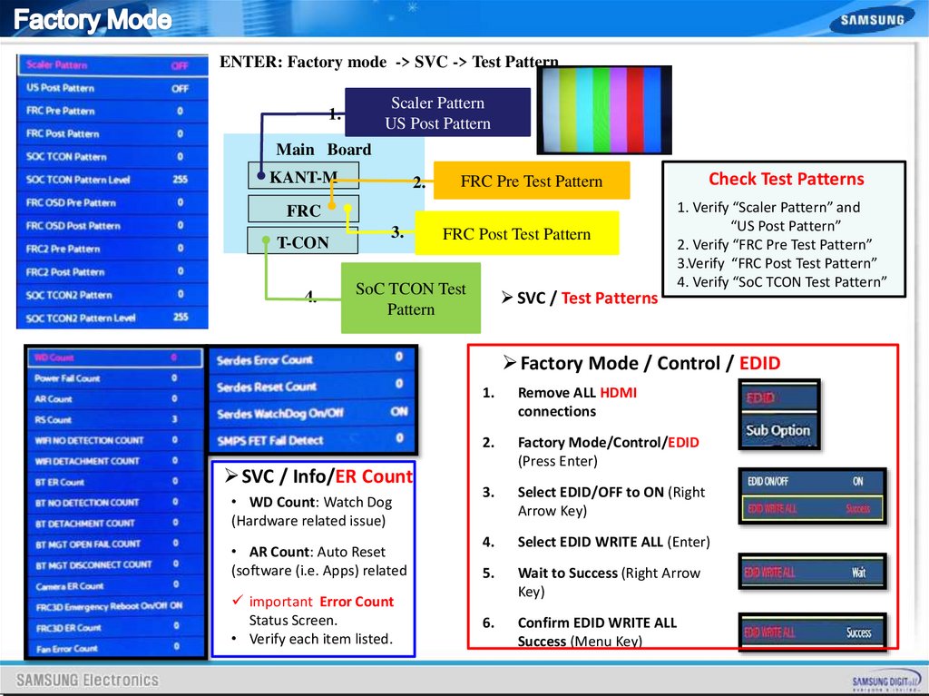
ENTER: Factory mode -> SVC -> Test PatternScaler Pattern
US Post Pattern
1.
Main Board
KANT-M
2.
FRC
T-CON
4.
3.
Check Test Patterns
FRC Pre Test Pattern
FRC Post Test Pattern
SoC TCON Test
Pattern
SVC / Test Patterns
1. Verify “Scaler Pattern” and
“US Post Pattern”
2. Verify “FRC Pre Test Pattern”
3.Verify “FRC Post Test Pattern”
4. Verify “SoC TCON Test Pattern”
Factory Mode / Control / EDID
1.
Remove ALL HDMI
connections
2.
Factory Mode/Control/EDID
(Press Enter)
• WD Count: Watch Dog
(Hardware related issue)
3.
Select EDID/OFF to ON (Right
Arrow Key)
• AR Count: Auto Reset
(software (i.e. Apps) related
4.
Select EDID WRITE ALL (Enter)
5.
Wait to Success (Right Arrow
Key)
6.
Confirm EDID WRITE ALL
Success (Menu Key)
SVC / Info/ER Count
important Error Count
Status Screen.
• Verify each item listed.
40.
41.
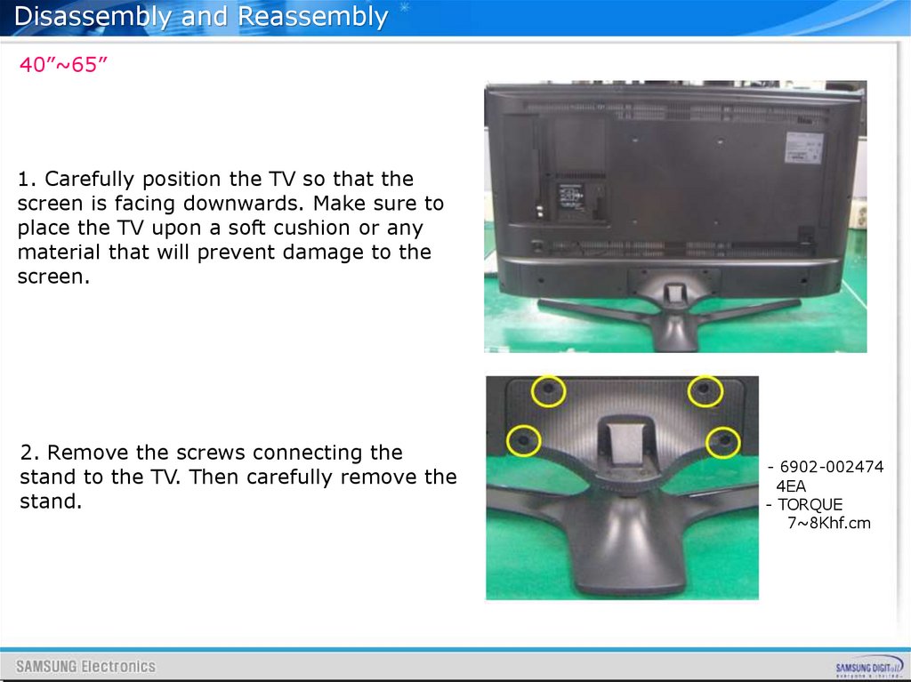
Disassembly and Reassembly40”~65”
1. Carefully position the TV so that the
screen is facing downwards. Make sure to
place the TV upon a soft cushion or any
material that will prevent damage to the
screen.
2. Remove the screws connecting the
stand to the TV. Then carefully remove the
stand.
- 6902-002474
4EA
- TORQUE
7~8Khf.cm
42.
Disassembly and Reassembly40”~65”
3. Remove the screws for the 'Rear
Cover'. Then carefully remove the
'Rear Cover'.
- 6001-002755
18EA
- TORQUE
7~8Khf.cm
4. Remove the Electric tapes shown
on the images.
※When assembling the TV, the electric
tapes must be applied on the same
locations. Please remember to take a
picture of where the tapes were first
applied.
43.
Disassembly and Reassembly40”~65”
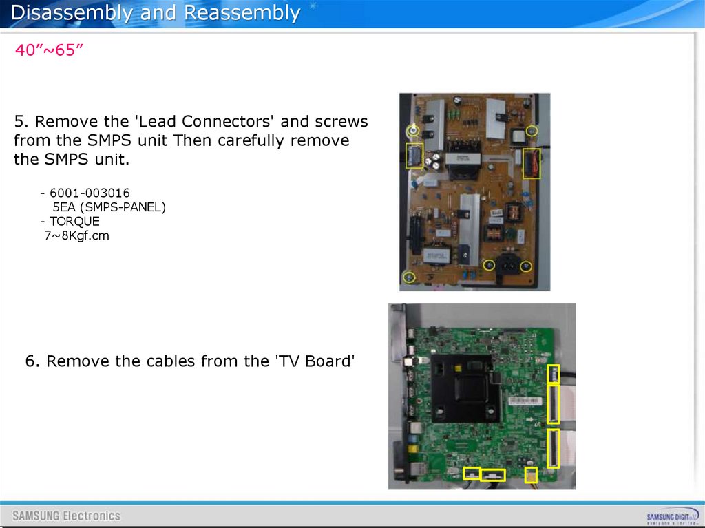
5. Remove the 'Lead Connectors' and screws
from the SMPS unit Then carefully remove
the SMPS unit.
- 6001-003016
5EA (SMPS-PANEL)
- TORQUE
7~8Kgf.cm
6. Remove the cables from the 'TV Board'
44.
Disassembly and Reassembly40”~65”
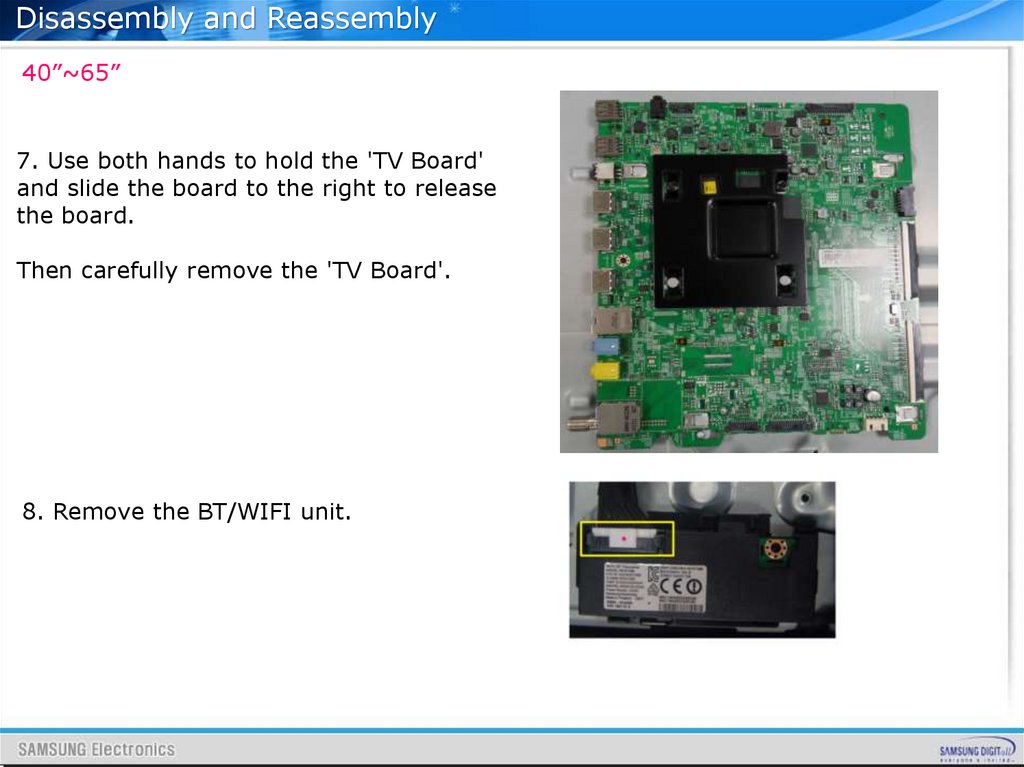
7. Use both hands to hold the 'TV Board'
and slide the board to the right to release
the board.
Then carefully remove the 'TV Board'.
8. Remove the BT/WIFI unit.
45.
Disassembly and Reassembly40”~65”
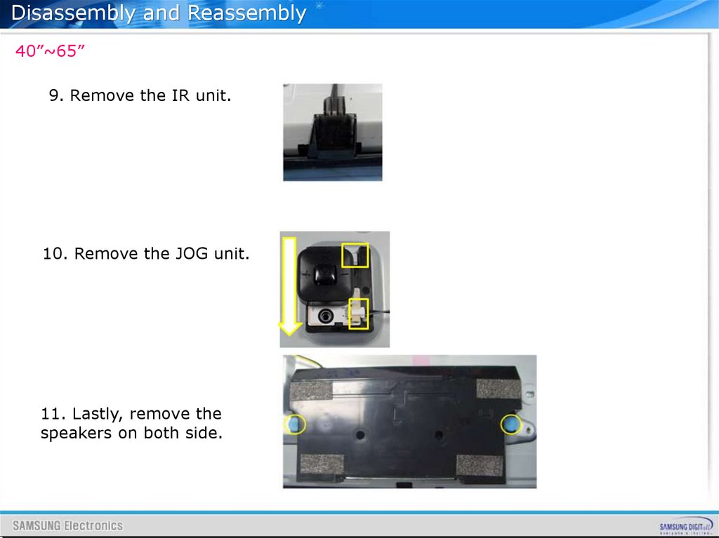
9. Remove the IR unit.
10. Remove the JOG unit.
11. Lastly, remove the
speakers on both side.
46.
Disassembly and Reassembly40”~65”
12. Completely Disassembly