


 electronics
Similar presentations:


 Wireless Audio - Soundbar ’2017 SAMSUNG ELECTRONICS CO.,LTD. VD R&D GROUP")

LCD TV LB350-650 Training manual. Inside of New Models
1.
LCD TVLB350-650
TRAINING MANUAL
2.
Inside ofNew Models
3.
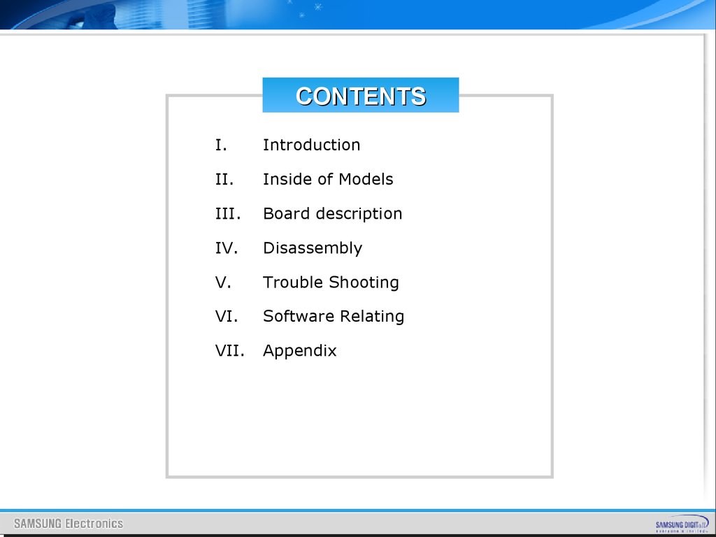
CONTENTSI.
Introduction
II.
Inside of Models
III.
Board description
IV.
Disassembly
V.
Trouble Shooting
VI.
Software Relating
VII.
Appendix
4.
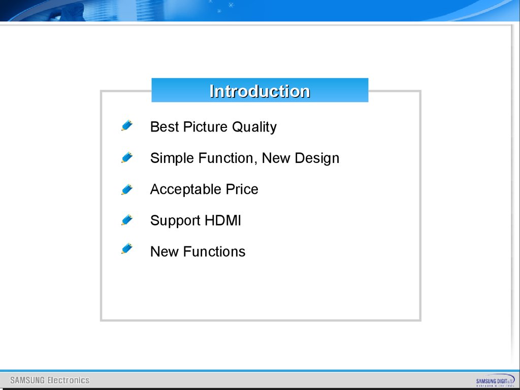
IntroductionBest Picture Quality
Simple Function, New Design
Acceptable Price
Support HDMI
New Functions
5.
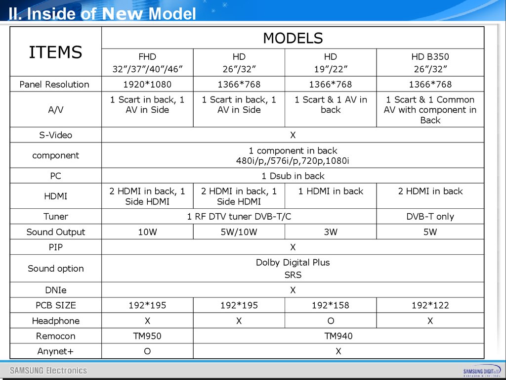
II. Inside of New ModelITEMS
MODELS
FHD
32”/37”/40”/46”
HD
26”/32”
HD
19”/22”
HD B350
26”/32”
Panel Resolution
1920*1080
1366*768
1366*768
1366*768
A/V
1 Scart in back, 1
AV in Side
1 Scart in back, 1
AV in Side
1 Scart & 1 AV in
back
1 Scart & 1 Common
AV with component in
Back
S-Video
X
component
1 component in back
480i/p,/576i/p,720p,1080i
PC
1 Dsub in back
HDMI
2 HDMI in back, 1
Side HDMI
Tuner
Sound Output
2 HDMI in back, 1
Side HDMI
1 HDMI in back
1 RF DTV tuner DVB-T/C
10W
5W/10W
2 HDMI in back
DVB-T only
3W
PIP
X
Sound option
Dolby Digital Plus
SRS
DNIe
X
5W
PCB SIZE
192*195
192*195
192*158
192*122
Headphone
X
X
O
X
Remocon
TM950
TM940
Anynet+
O
X
6.
Remote Controller TypeTOOLS [RF]
Picture Size
Picture Mode
Sound Mode
TM950
TM940
TOOLS [PC]
POWER
TV
Sleep Timer
Sound Mode
Sleep Timer
Energy Saving
Energy Saving
Dual I-II
Auto Adjustment
MUTE
TOOLS [HDMI, AV,
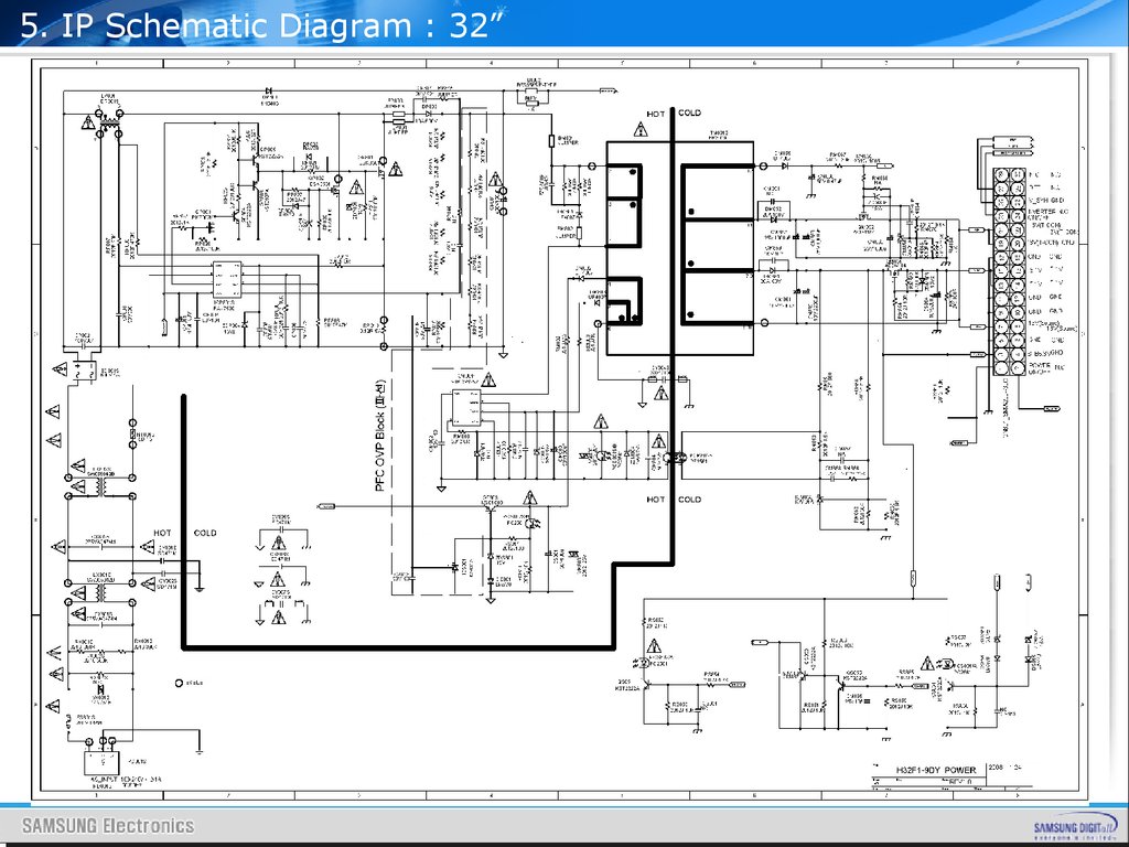
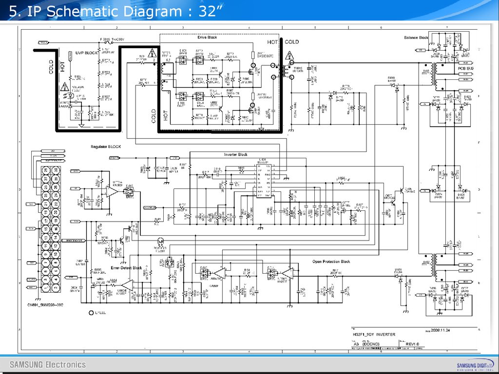
Scart, Component]
SOURCE
P
Picture Size
MUTE
TOOLS [HDMI,
AV, Scart,
Component]
Picture Mode
CHLIST
MENU
TOOLS
FAV.CH
Sound Mode
RETURN
Sleep Timer
Sleep Timer
Energy Saving
SRS TruSurround
HD
TOOLS [RF]
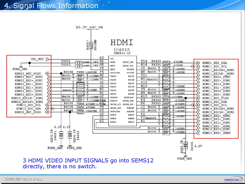
Energy Saving
TOOLS [PC]
Picture Size
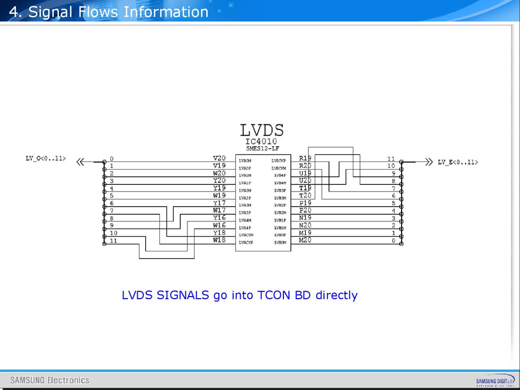
Picture Mode
Sound Mode
Sleep Timer
SRS TruSurround
HD
Energy Saving
Auto Adjustment
PRE-CH
PRE-CH
Add to Favorite
Sound Mode
TV
Picture Mode
SRS TruSurround
HD
Picture Mode
POWER
INFO
TTX/MIX
EXIT
GUIDE
SUBT.
SOURCE
CHLIST
MENU
P
FAV.CH
TOOLS
RETURN
INFO
EXIT
Picture Mode
Sound Mode
TTX/MIX
SRS
P.SIZE
Sleep Timer
DUAL
GUIDE
SUBT.
Energy Saving
Add to Favorite
7.
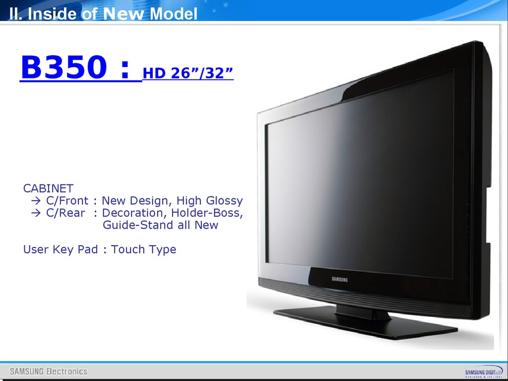
II. Inside of New ModelB350 :
HD 26”/32”
CABINET
C/Front : New Design, High Glossy
C/Rear : Decoration, Holder-Boss,
Guide-Stand all New
User Key Pad : Touch Type
8.
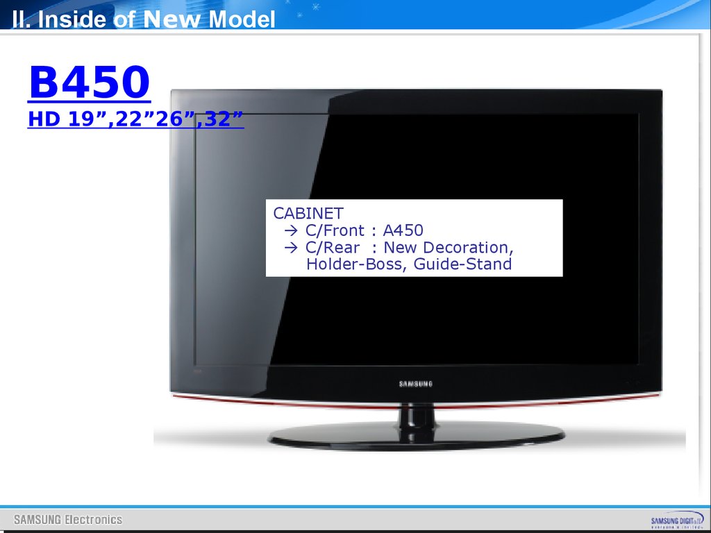
II. Inside of New ModelB450
HD 19”,22”26”,32”
CABINET
C/Front : A450
C/Rear : New Decoration,
Holder-Boss, Guide-Stand
9.
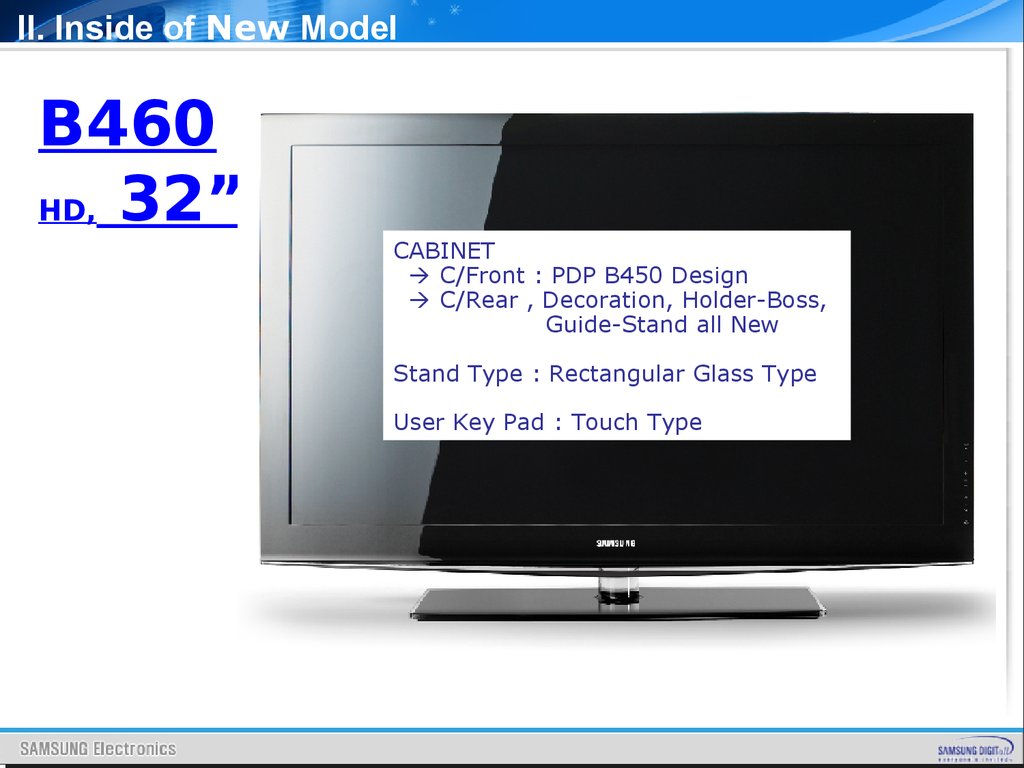
II. Inside of New ModelB460
HD, 32”
CABINET
C/Front : PDP B450 Design
C/Rear , Decoration, Holder-Boss,
Guide-Stand all New
Stand Type : Rectangular Glass Type
User Key Pad : Touch Type
10.
II. Inside of New ModelB530
FHD 32”,37”,40”,46”
CABINET
C/Front : A550 P3
C/Rear, New Decoration,
Holder-Boss, Guide-Stand
Stand : Rectangular Mold-Stand
11.
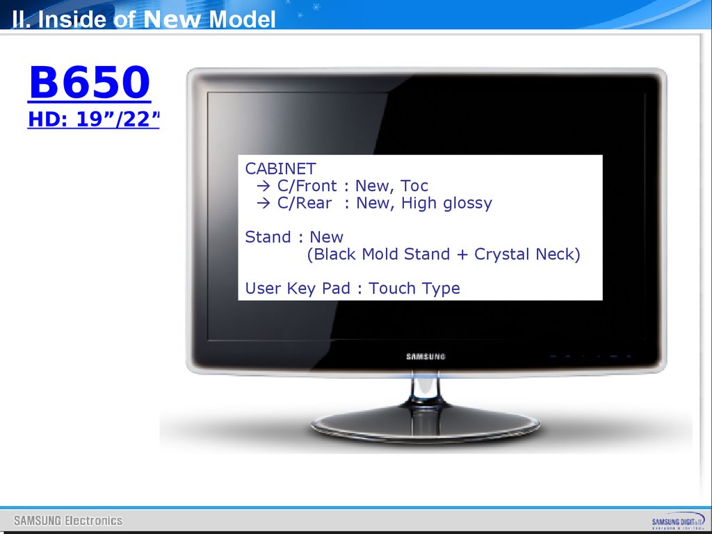
II. Inside of New ModelB650
HD: 19”/22”
CABINET
C/Front : New, Toc
C/Rear : New, High glossy
Stand : New
(Black Mold Stand + Crystal Neck)
User Key Pad : Touch Type
12.
II. Inside of New ModelControl & Connection Panel
New Model
13.
II. Inside of New ModelLast year Model
14.
II. Inside of New ModelControl & Connection Panel
15.
II. Inside of New ModelControl & Connection Panel
16.
II. Inside of New ModelControl & Connection Panel
17.
II. Inside of New Model18.
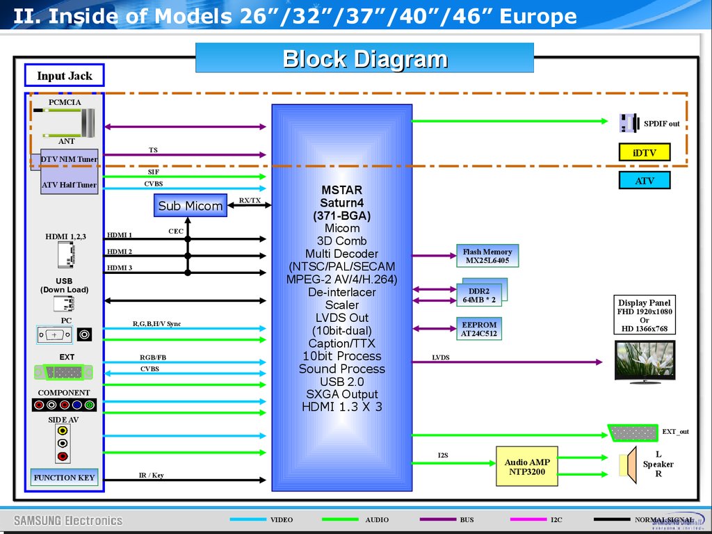
II. Inside of Models 26”/32”/37”/40”/46” EuropeBlock Diagram
Input Jack
PCMCIA
SPDIF out
ANT
TS
iDTV
DTV NIM Tuner
SIF
CVBS
ATV Half Tuner
Sub Micom
HDMI 1,2,3
CEC
HDMI 1
HDMI 2
HDMI 3
USB
(Down Load)
PC
EXT
R,G,B,H/V Sync
RGB/FB
CVBS
COMPONENT
RX/TX
MSTAR
Saturn4
(371-BGA)
Micom
3D Comb
Multi Decoder
(NTSC/PAL/SECAM
MPEG-2 AV/4/H.264)
De-interlacer
Scaler
LVDS Out
(10bit-dual)
Caption/TTX
10bit Process
Sound Process
USB 2.0
SXGA Output
HDMI 1.3 X 3
ATV
Flash Memory
MX25L6405
DDR2
64MB * 2
Display Panel
FHD 1920x1080
Or
HD 1366x768
EEPROM
AT24C512
LVDS
SIDE AV
EXT_out
I2S
FUNCTION KEY
IR / Key
VIDEO
AUDIO
L
Speaker
R
Audio AMP
NTP3200
BUS
I2C
NORMAL SIGNAL
19.
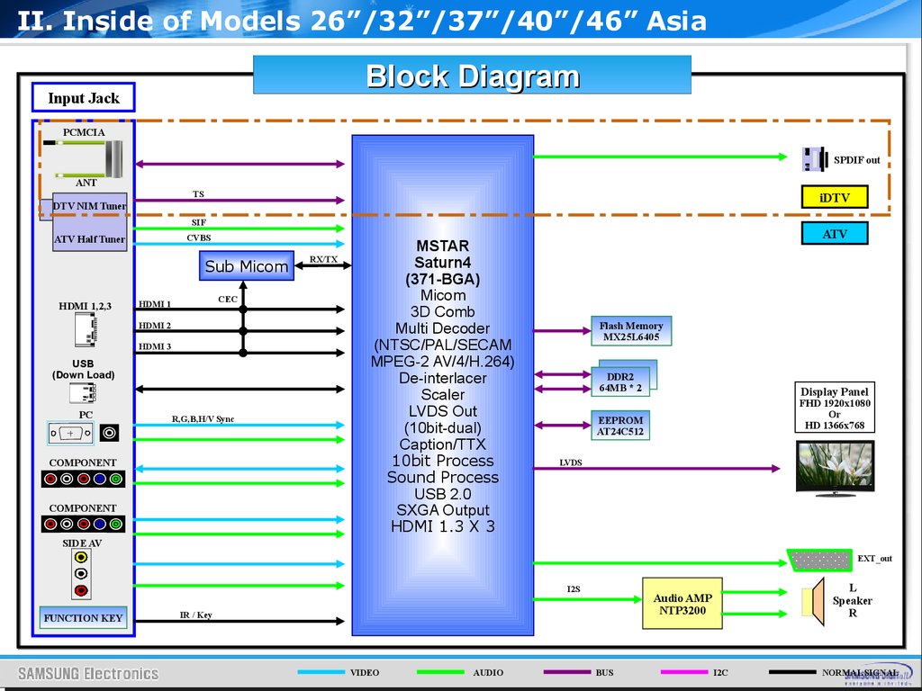
II. Inside of Models 26”/32”/37”/40”/46” AsiaBlock Diagram
Input Jack
PCMCIA
SPDIF out
ANT
TS
iDTV
DTV NIM Tuner
SIF
CVBS
ATV Half Tuner
Sub Micom
HDMI 1,2,3
CEC
HDMI 1
HDMI 2
HDMI 3
USB
(Down Load)
PC
R,G,B,H/V Sync
COMPONENT
COMPONENT
RX/TX
MSTAR
Saturn4
(371-BGA)
Micom
3D Comb
Multi Decoder
(NTSC/PAL/SECAM
MPEG-2 AV/4/H.264)
De-interlacer
Scaler
LVDS Out
(10bit-dual)
Caption/TTX
10bit Process
Sound Process
USB 2.0
SXGA Output
HDMI 1.3 X 3
ATV
Flash Memory
MX25L6405
DDR2
64MB * 2
Display Panel
FHD 1920x1080
Or
HD 1366x768
EEPROM
AT24C512
LVDS
SIDE AV
EXT_out
I2S
FUNCTION KEY
IR / Key
VIDEO
AUDIO
L
Speaker
R
Audio AMP
NTP3200
BUS
I2C
NORMAL SIGNAL
20.
II. Inside of Model 19”/22” EuropeBlock Diagram
Input Jack
PCMCIA
SPDIF out
ANT
TS
iDTV
DTV NIM Tuner
SIF
CVBS
ATV Half Tuner
Sub Micom
HDMI 1
CEC
HDMI 1
USB
(Down Load)
PC
EXT
R,G,B,H/V Sync
RGB/FB
CVBS
COMPONENT
RX/TX
MSTAR
Saturn4
(371-BGA)
Micom
3D Comb
Multi Decoder
(NTSC/PAL/SECAM
MPEG-2 AV/4/H.264)
De-interlacer
Scaler
LVDS Out
(10bit-dual)
Caption/TTX
10bit Process
Sound Process
USB 2.0
SXGA Output
HDMI 1.3 X 3
ATV
Flash Memory
MX25L6405
DDR2
64MB * 2
Display Panel
FHD 1920x1080
Or
HD 1366x768
EEPROM
AT24C512
LVDS
MAX9728
Head Phone
AV
EXT_out
I2S
FUNCTION KEY
IR / Key
VIDEO
AUDIO
L
Speaker
R
Audio AMP
NTP3200
BUS
I2C
NORMAL SIGNAL
21.
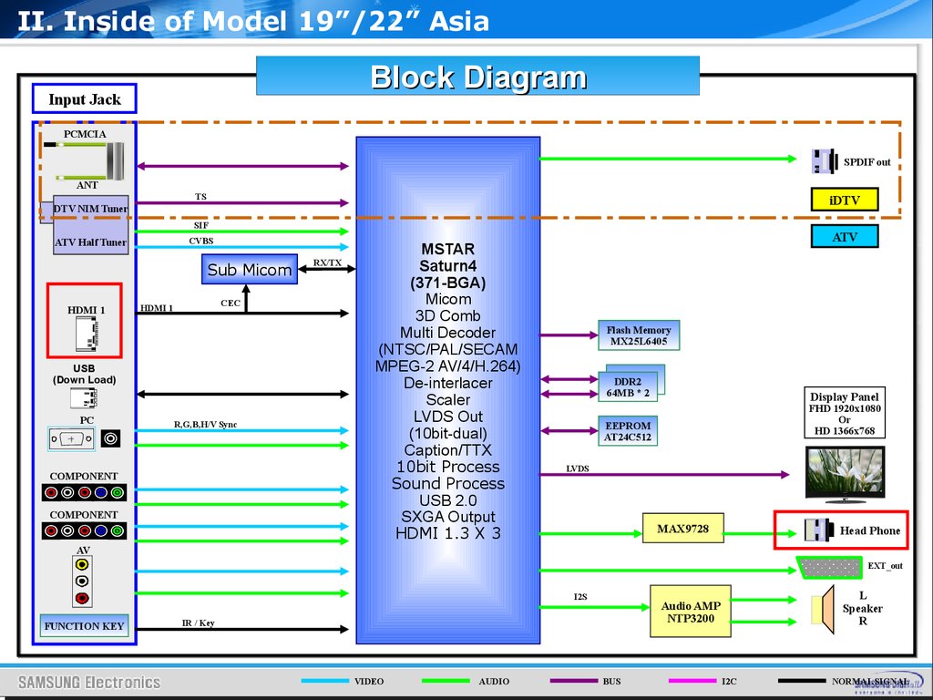
II. Inside of Model 19”/22” AsiaBlock Diagram
Input Jack
PCMCIA
SPDIF out
ANT
TS
iDTV
DTV NIM Tuner
SIF
CVBS
ATV Half Tuner
Sub Micom
HDMI 1
CEC
HDMI 1
USB
(Down Load)
PC
R,G,B,H/V Sync
COMPONENT
COMPONENT
RX/TX
MSTAR
Saturn4
(371-BGA)
Micom
3D Comb
Multi Decoder
(NTSC/PAL/SECAM
MPEG-2 AV/4/H.264)
De-interlacer
Scaler
LVDS Out
(10bit-dual)
Caption/TTX
10bit Process
Sound Process
USB 2.0
SXGA Output
HDMI 1.3 X 3
ATV
Flash Memory
MX25L6405
DDR2
64MB * 2
Display Panel
FHD 1920x1080
Or
HD 1366x768
EEPROM
AT24C512
LVDS
MAX9728
Head Phone
AV
EXT_out
I2S
FUNCTION KEY
IR / Key
VIDEO
AUDIO
L
Speaker
R
Audio AMP
NTP3200
BUS
I2C
NORMAL SIGNAL
22.
II. Inside of B350 Models 26”/32”Block Diagram
Input Jack
PCMCIA
SPDIF out
ANT
TS
iDTV
DTV NIM Tuner
SIF
CVBS
ATV Half Tuner
HDMI 1,2
HDMI 1
HDMI 2
USB
(Down Load)
PC
EXT
R,G,B,H/V Sync
RGB/FB
CVBS
COMPONENT
MSTAR
Saturn4
(371-BGA)
Micom
3D Comb
Multi Decoder
(NTSC/PAL/SECAM
MPEG-2 AV/4/H.264)
De-interlacer
Scaler
LVDS Out
(10bit-dual)
Caption/TTX
10bit Process
Sound Process
USB 2.0
SXGA Output
HDMI 1.3 X 3
ATV
Flash Memory
MX25L6405
DDR2
64MB * 2
Display Panel
FHD 1920x1080
Or
HD 1366x768
EEPROM
AT24C512
LVDS
EXT_out
I2S
FUNCTION KEY
IR / Key
VIDEO
AUDIO
L
Speaker
R
Audio AMP
NTP3200
BUS
I2C
NORMAL SIGNAL
23.
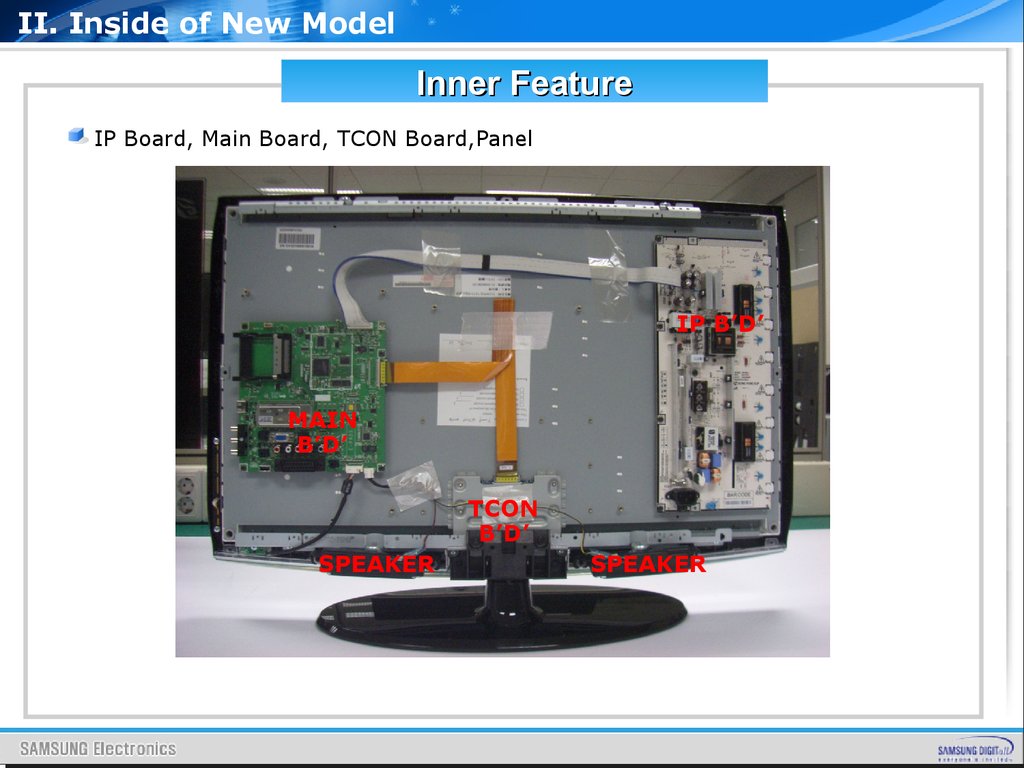
II. Inside of New ModelInner Feature
IP Board, Main Board, TCON Board,Panel
IP B’D’
MAIN
B’D’
TCON
B’D’
SPEAKER
SPEAKER
24.
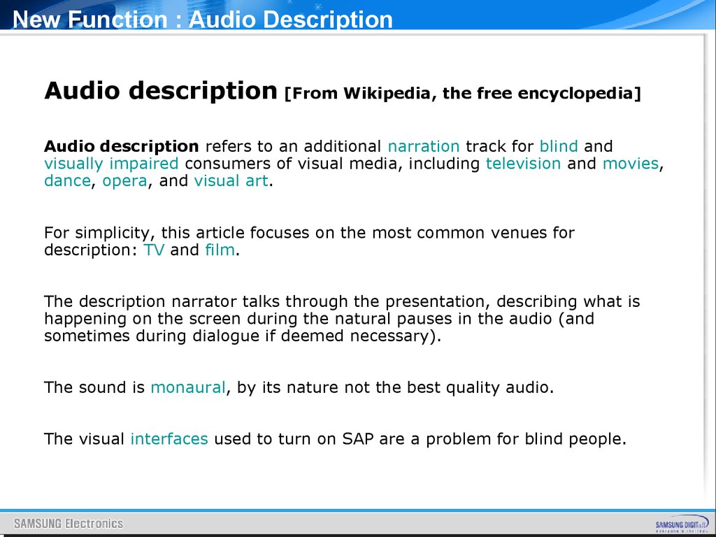
New Function : Audio DescriptionAudio description [From Wikipedia, the free encyclopedia]
Audio description refers to an additional narration track for blind and
visually impaired consumers of visual media, including television and movies,
dance, opera, and visual art.
For simplicity, this article focuses on the most common venues for
description: TV and film.
The description narrator talks through the presentation, describing what is
happening on the screen during the natural pauses in the audio (and
sometimes during dialogue if deemed necessary).
The sound is monaural, by its nature not the best quality audio.
The visual interfaces used to turn on SAP are a problem for blind people.
25.
New Function : Audio Description26.
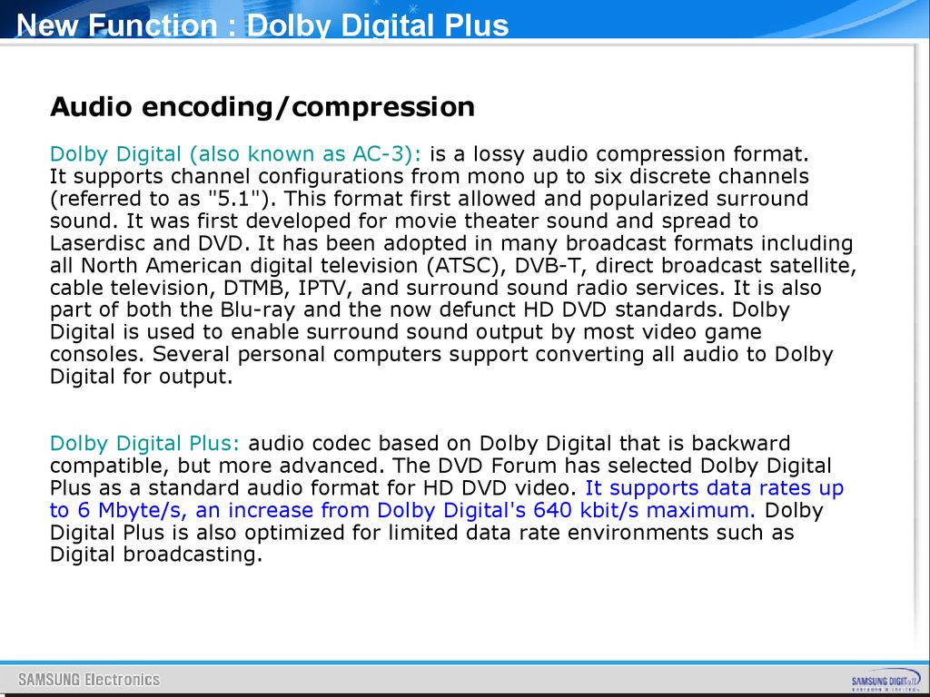
New Function : Dolby Digital PlusAudio encoding/compression
Dolby Digital (also known as AC-3): is a lossy audio compression format.
It supports channel configurations from mono up to six discrete channels
(referred to as "5.1"). This format first allowed and popularized surround
sound. It was first developed for movie theater sound and spread to
Laserdisc and DVD. It has been adopted in many broadcast formats including
all North American digital television (ATSC), DVB-T, direct broadcast satellite,
cable television, DTMB, IPTV, and surround sound radio services. It is also
part of both the Blu-ray and the now defunct HD DVD standards. Dolby
Digital is used to enable surround sound output by most video game
consoles. Several personal computers support converting all audio to Dolby
Digital for output.
Dolby Digital Plus: audio codec based on Dolby Digital that is backward
compatible, but more advanced. The DVD Forum has selected Dolby Digital
Plus as a standard audio format for HD DVD video. It supports data rates up
to 6 Mbyte/s, an increase from Dolby Digital's 640 kbit/s maximum. Dolby
Digital Plus is also optimized for limited data rate environments such as
Digital broadcasting.
27.
New Function : SRS TruSurround HDDialog Clarity. Audio creators today have more sound tools than ever to
work with, and more channels to put sound in. So naturally, they create rich,
dense audio for any purpose—movies, TV, music and games. Problem is, with
such heavily layered audio tracks, sometimes the vocals and dialog get lost
in the shuffle … or buried under sound effects. Dialog Clarity boosts the
frequency range of the human voice in a way that makes the human voice
rise above the audio effects, so you can hear clearly every word you’re
supposed to hear.
Immersive Surround Sound. This is the core technology of all the
TruSurround suites, and it processes any multichannel input, sending it to
two or three TV speakers after some very sophisticated processing. This
allows the listener to perceive enveloping surround sound from just the TV
speakers or external speaker bar. Rear and surround channels are processed
separately from front channels, and through our study of psychoacoustics
and knowing the difference between how sound is perceived front to back,
we process and adjust the surround channels’ waveforms so they are
perceived as coming from behind the listener.
, and the restoration really is magic.
28.
New Function : SRS TruSurround HDImproved Bass. We know small speakers cannot reproduce deep bass. It’s
physically impossible. But bass sounds are always accompanied by
overtones, and if your ears are given all the overtones, your perception will
fill in the ‘missing fundamental.’ SRS patented bass technology was
developed based on an amazing combination of psychoacoustic
understanding and technical know-how, managing to restore the sensation of
deep bass. It identifies the signals that cannot be reproduced, and restores
and boosts the overtones. It’s all in your head, courtesy of some nifty audio
wave processing, and the restoration really is magic.
High Frequency Clarity. Techniques used in digital compression or
broadcast transmission can reduce the clarity of audio content, leaving you
with a rather lackluster audio experience. SRS’ premium high definition
technology restores clarity by enhancing the high frequency content, bringing
into focus the rain falling or wind howling in a movie scene or the cymbals
and acoustic guitar strumming in your favorite song.
29.
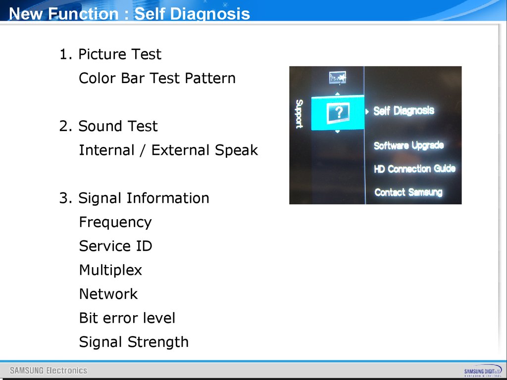
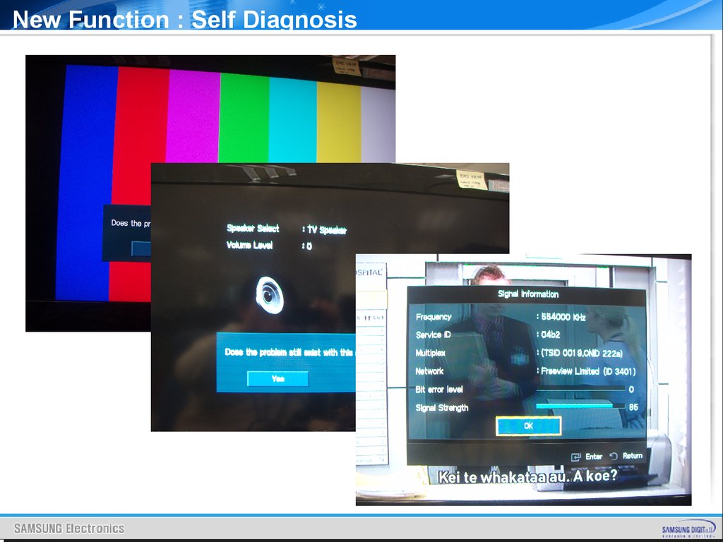
New Function : Self Diagnosis1. Picture Test
Color Bar Test Pattern
2. Sound Test
Internal / External Speak
3. Signal Information
Frequency
Service ID
Multiplex
Network
Bit error level
Signal Strength
30.
New Function : Self Diagnosis31.
New Function : Alternative Software32.
OSD Menu TreeProject Name:
Saturn4 DVB
Created:
Product:
LCD TV
System:
DVB(2009)
Date:
2008-11-26
OSD MENU
TREE
33.
II. Inside of New ModelKey parts
SCALER : SEMS12
SOUND AMP : NTP3200
34.
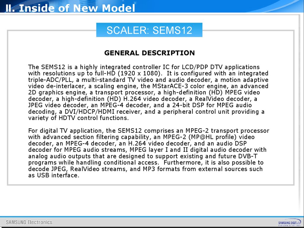
Ⅱ. Inside of New ModelSCALER: SEMS12
GENERAL DESCRIPTION
The SEMS12 is a highly integrated controller IC for LCD/PDP DTV applications
with resolutions up to full-HD (1920 x 1080). It is configured with an integrated
triple-ADC/PLL, a multi-standard TV video and audio decoder, a motion adaptive
video de-interlacer, a scaling engine, the MStarACE-3 color engine, an advanced
2D graphics engine, a transport processor, a high-definition (HD) MPEG video
decoder, a high-definition (HD) H.264 video decoder, a RealVideo decoder, a
JPEG video decoder, an MPEG-4 decoder, and a 24-bit DSP for MPEG audio
decoding, a DVI/HDCP/HDMI receiver, and a peripheral control unit providing a
variety of HDTV control functions.
For digital TV application, the SEMS12 comprises an MPEG-2 transport processor
with advanced section filtering capability, an MPEG-2 (MP@HL profile) video
decoder, an MPEG-4 decoder, an H.264 video decoder, and an audio DSP
decoder for MPEG audio streams, MPEG layer I and II digital audio decoder with
analog audio outputs that are designed to support existing and future DVB-T
programs while handling conditional access. Furthermore, it is also possible to
decode JPEG, RealVideo streams, and MP3 formats from external sources such
as USB interface.
35.
Ⅱ. Inside of New ModelSCALER: SEMS12
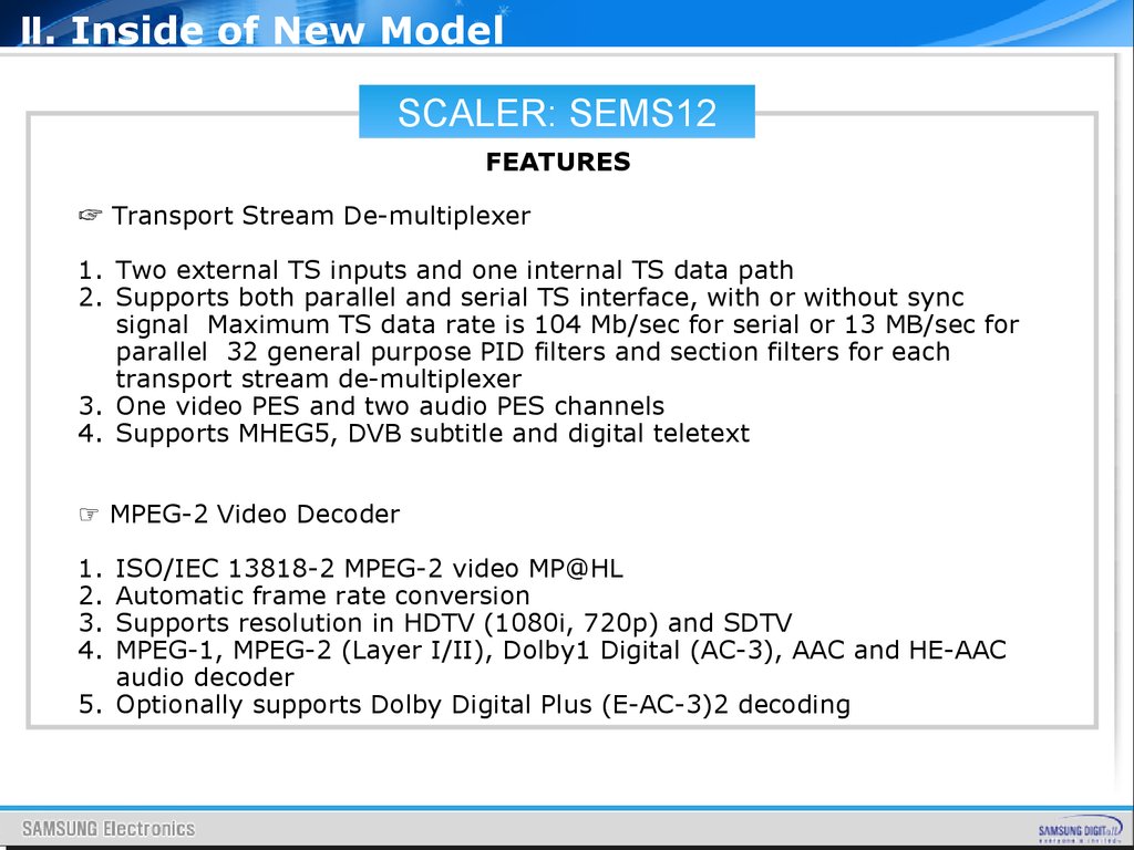
FEATURES
☞ Transport Stream De-multiplexer
1. Two external TS inputs and one internal TS data path
2. Supports both parallel and serial TS interface, with or without sync
signal Maximum TS data rate is 104 Mb/sec for serial or 13 MB/sec for
parallel 32 general purpose PID filters and section filters for each
transport stream de-multiplexer
3. One video PES and two audio PES channels
4. Supports MHEG5, DVB subtitle and digital teletext
☞ MPEG-2 Video Decoder
1.
2.
3.
4.
ISO/IEC 13818-2 MPEG-2 video MP@HL
Automatic frame rate conversion
Supports resolution in HDTV (1080i, 720p) and SDTV
MPEG-1, MPEG-2 (Layer I/II), Dolby1 Digital (AC-3), AAC and HE-AAC
audio decoder
5. Optionally supports Dolby Digital Plus (E-AC-3)2 decoding
36.
Ⅱ. Inside of New ModelSCALER: SEMS12
☞ MPEG-4 Video Decoder
1. ISO/IEC 14496-2 MPEG-4 ASP video decoding
2. Supports resolution in HDTV (1080p@30fps) for MPEG-4
☞ H.264 Decoder
1. Fully compliant with ITU-T H.264, ISO/IEC 14496-10 (main and high
profile up to level 4.0)
2. Supports all DVB, ATSC, HDTV, DVD, VCD resolutions (e.g. 1080p,
1080i, 720p, D1)
3. Supports picture size from 80x96 pixel to 1920x1088 pixel
4. Decodes up to 1080p@30 fps
5. Reads streams from Transport and from files
6. Supports stream types of CABAC and CAVLC
7. Processing of ES and PES streams, extraction and provision of time
stamps
8. Allegro H.264 certification test suite proven
9. ITU-T H.264 conformance tests proven
10.Error detection and concealment
37.
Ⅱ. Inside of New ModelSCALER: SEMS12
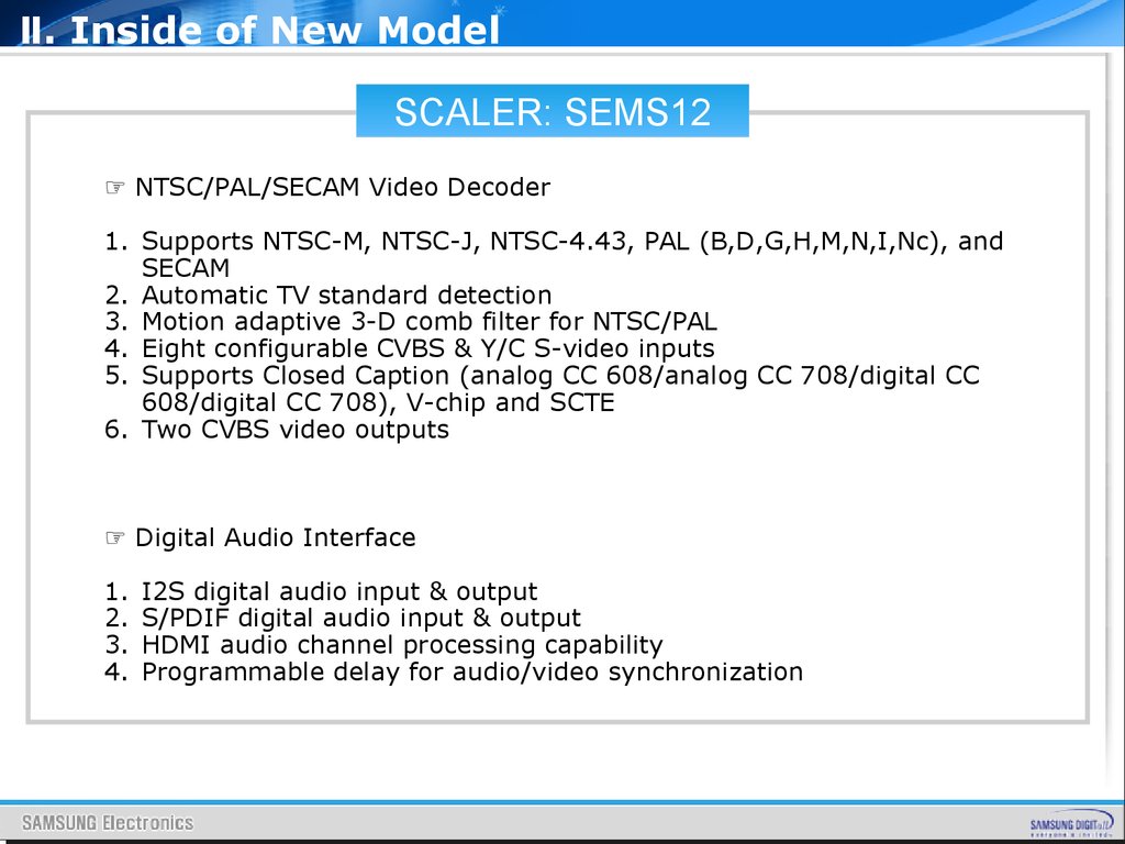
☞ NTSC/PAL/SECAM Video Decoder
1. Supports NTSC-M, NTSC-J, NTSC-4.43, PAL (B,D,G,H,M,N,I,Nc), and
SECAM
2. Automatic TV standard detection
3. Motion adaptive 3-D comb filter for NTSC/PAL
4. Eight configurable CVBS & Y/C S-video inputs
5. Supports Closed Caption (analog CC 608/analog CC 708/digital CC
608/digital CC 708), V-chip and SCTE
6. Two CVBS video outputs
☞ Digital Audio Interface
1.
2.
3.
4.
I2S digital audio input & output
S/PDIF digital audio input & output
HDMI audio channel processing capability
Programmable delay for audio/video synchronization
38.
Ⅱ. Inside of New ModelSCALER: SEMS12
☞ Multi-Standard TV Sound Processor
1. Supports BTSC/A2/EIA-J demodulation in NTSC and
A2/NICAM/FM/AM demodulation in PAL
2. Supports MTS Mode Mono/Stereo/SAP in BTSC/ EIA-J and
Mono/Stereo/Dual in A2/NICAM
3. L/R audio line-in x6 and SIF audio input
4. L/R speaker and 2 additional L/R audio line-out
5. Built-in audio sampling rate conversion (SRC)
6. Built-in audio output DAC’s
7. Supports audio description (AD)
8. Audio processing for loudspeaker channel, including volume,
balance, mute, tone, EQ, virtual stereo/surround, and treble/bass
9. Supports MP3 decoding
10.Optionally supports Dolby Digital (AC-3) encoding at SPDIF
output
11.Optional advanced sound3 available (Dolby, SRS4, BBE5… etc)
39.
Ⅱ. Inside of New ModelSCALER: SEMS12
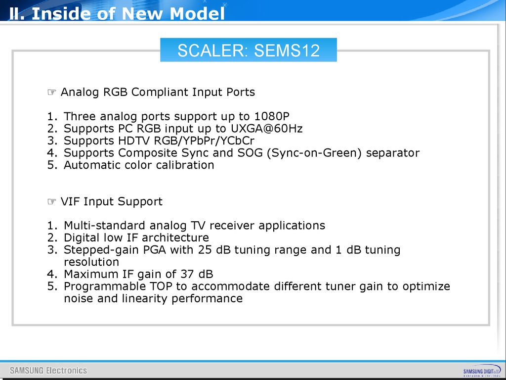
☞ Analog RGB Compliant Input Ports
1.
2.
3.
4.
5.
Three analog ports support up to 1080P
Supports PC RGB input up to UXGA@60Hz
Supports HDTV RGB/YPbPr/YCbCr
Supports Composite Sync and SOG (Sync-on-Green) separator
Automatic color calibration
☞ VIF Input Support
1. Multi-standard analog TV receiver applications
2. Digital low IF architecture
3. Stepped-gain PGA with 25 dB tuning range and 1 dB tuning
resolution
4. Maximum IF gain of 37 dB
5. Programmable TOP to accommodate different tuner gain to optimize
noise and linearity performance
40.
Ⅱ. Inside of New ModelSCALER: SEMS12
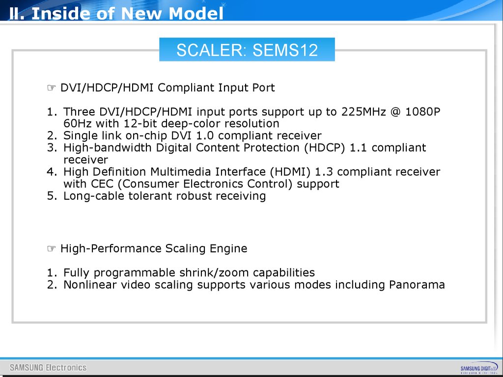
☞ DVI/HDCP/HDMI Compliant Input Port
1. Three DVI/HDCP/HDMI input ports support up to 225MHz @ 1080P
60Hz with 12-bit deep-color resolution
2. Single link on-chip DVI 1.0 compliant receiver
3. High-bandwidth Digital Content Protection (HDCP) 1.1 compliant
receiver
4. High Definition Multimedia Interface (HDMI) 1.3 compliant receiver
with CEC (Consumer Electronics Control) support
5. Long-cable tolerant robust receiving
☞ High-Performance Scaling Engine
1. Fully programmable shrink/zoom capabilities
2. Nonlinear video scaling supports various modes including Panorama
41.
Ⅱ. Inside of New ModelSCALER: SEMS12
☞ Video Processing & Conversion
1. 3-D motion adaptive video de-interlacers with edge-oriented adaptive
algorithm for smooth low-angle edges
2. Automatic 3:2 pull-down & 2:2 pull-down detection and recovery
3. MStar 3rd Generation Advanced Color Engine (MStarACE-3) automatic
picture enhancement gives:
a. Brilliant and fresh color
b. Intensified contrast and details
c. Vivid skin tone
d. Sharp edge
e. Enhanced depth of field perception
f. Accurate and independent color control
4. sRGB compliance allows end-user to experience the same colors as
viewed on CRTs and other displays
5. 3-channel gamma curve adjustment
6. 10-bit internal data processing
42.
Ⅱ. Inside of New ModelSCALER: SEMS12
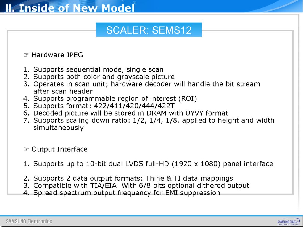
☞ Hardware JPEG
1. Supports sequential mode, single scan
2. Supports both color and grayscale picture
3. Operates in scan unit; hardware decoder will handle the bit stream
after scan header
4. Supports programmable region of interest (ROI)
5. Supports format: 422/411/420/444/422T
6. Decoded picture will be stored in DRAM with UYVY format
7. Supports scaling down ratio: 1/2, 1/4, 1/8, applied to height and width
simultaneously
☞ Output Interface
1. Supports up to 10-bit dual LVDS full-HD (1920 x 1080) panel interface
2. Supports 2 data output formats: Thine & TI data mappings
3. Compatible with TIA/EIA With 6/8 bits optional dithered output
4. Spread spectrum output frequency for EMI suppression
43.
Ⅱ. Inside of New ModelSOUND AMP:NTP3200
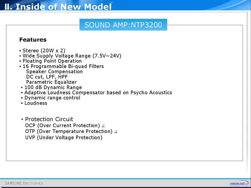
Features
▪
▪
▪
▪
Stereo (20W ⅹ 2)
Wide Supply Voltage Range (7.5V~24V)
Floating Point Operation
16 Programmable Bi-quad Filters
Speaker Compensation
DC cut, LPF, HPF
Parametric Equalizer
▪ 100 dB Dynamic Range
▪ Adaptive Loudness Compensator based on Psycho Acoustics
▪ Dynamic range control
▪ Loudness
▪ Protection Circuit
OCP (Over Current Protection)
OTP (Over Temperature Protection)
UVP (Under Voltage Protection)
44.
Ⅱ. Inside of New ModelSOUND AMP:NTP3200
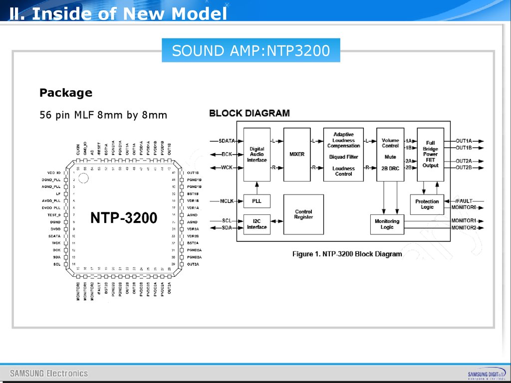
Description
The NTP-3200 is a single chip full digital audio amplifier including power
stage for stereo amplifier system. NTP-3200 is integrated with versatile
digital audio signal processing functions, high-performance, high-fidelity
fully digital PWM modulator and two high-power full bridge MOSFET
power stages.
The NTP-3200 receives digital serial audio data with sampling frequency
from 8KHz to 192KHz. It delivers 2 x 20 watt in stereo mode without heat
sink. The NTP-3200 has mixer and Bi-Quad filters which can be used to
implement the essential audio signal processing functions like loudness
control, loud speaker response compensation and parametric equalizers.
All the functions of the NTP-3200 can be controlled by internal register
values via I2C host interface bus.
45.
Ⅱ. Inside of New ModelSOUND AMP:NTP3200
Package
56 pin MLF 8mm by 8mm
46.
Ⅱ. Inside of New ModelSOUND AMP:NTP3200
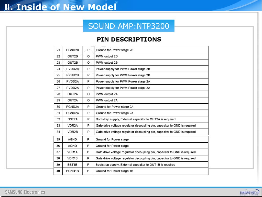
PIN DESCRIPTIONS
47.
Ⅱ. Inside of New ModelSOUND AMP:NTP3200
PIN DESCRIPTIONS
48.
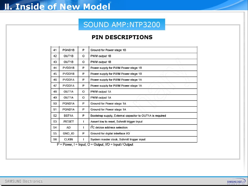
Ⅱ. Inside of New ModelSOUND AMP:NTP3200
PIN DESCRIPTIONS
49.
Ⅲ. Board descriptionBOARD
DESCRIPTION
50.
Ⅲ. Board descriptionCONTENTS
1.
MAIN BOARD LAYOUT
2.
MAIN BOARD PIN CHARACTERISTIC
3.
IP BOARD INPUT CHARACTERISTIC
4.
POWER OUTPUT CHARACTERISTIC
5.
INVERTER OUTPUT CHARACTERISTIC
6.
ENVIRONMENTAL CHARACTERISTIC
7.
IP BOARD LAYOUT
8.
IP BOARD PIN CHARACTERISTIC
51.
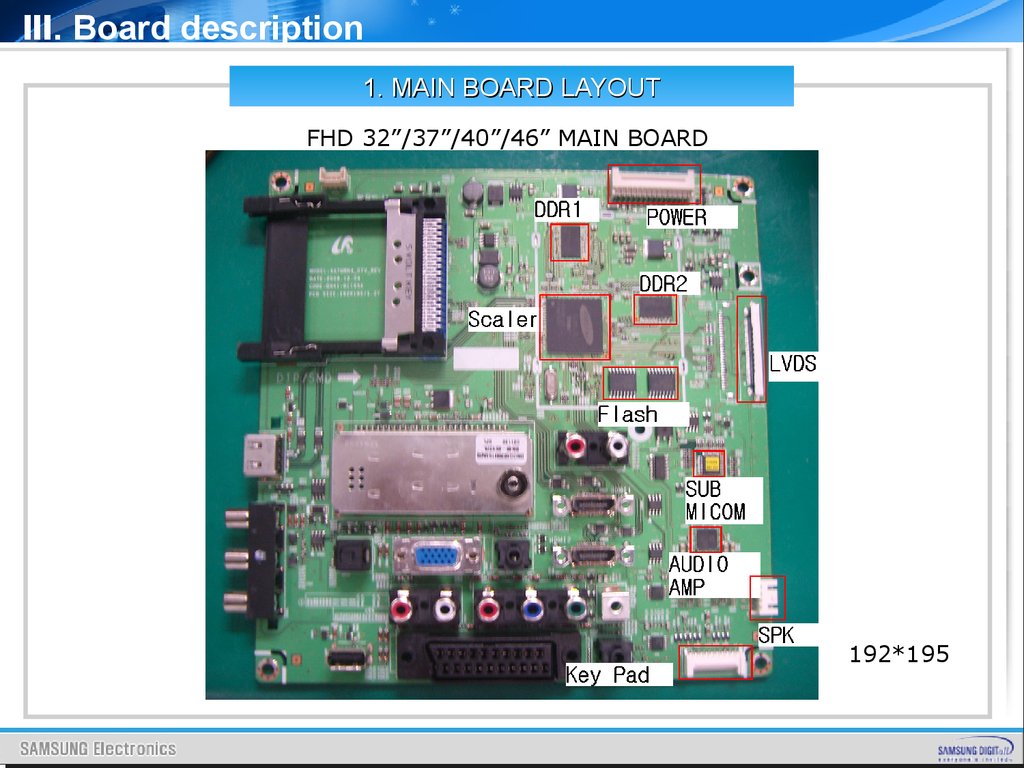
Ⅲ. Board description1. MAIN BOARD LAYOUT
FHD 32”/37”/40”/46” MAIN BOARD
192*195
52.
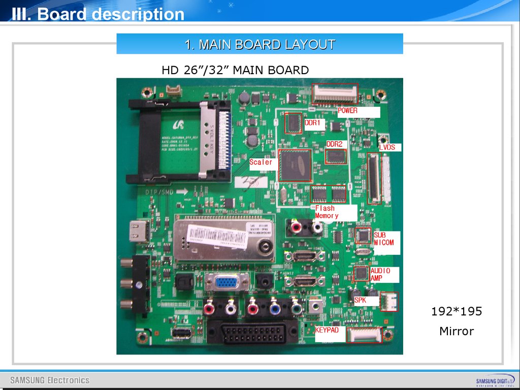
Ⅲ. Board description1. MAIN BOARD LAYOUT
HD 26”/32” MAIN BOARD
192*195
Mirror
53.
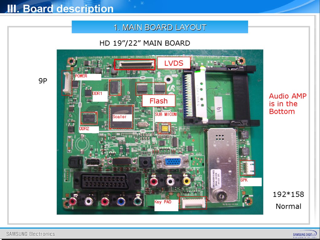
Ⅲ. Board description1. MAIN BOARD LAYOUT
HD 19”/22” MAIN BOARD
LVDS
9P
Flash
Audio AMP
is in the
Bottom
192*158
Normal
54.
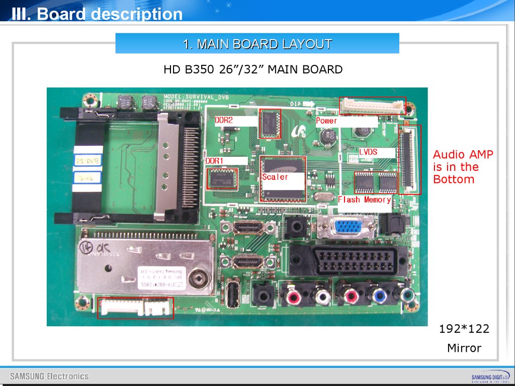
Ⅲ. Board description1. MAIN BOARD LAYOUT
HD B350 26”/32” MAIN BOARD
Audio AMP
is in the
Bottom
192*122
Mirror
55.
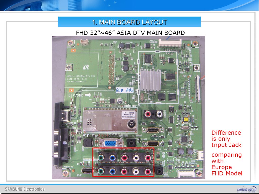
1. MAIN BOARD LAYOUTFHD 32”~46” ASIA DTV MAIN BOARD
Difference
is only
Input Jack
comparing
with
Europe
FHD Model
56.
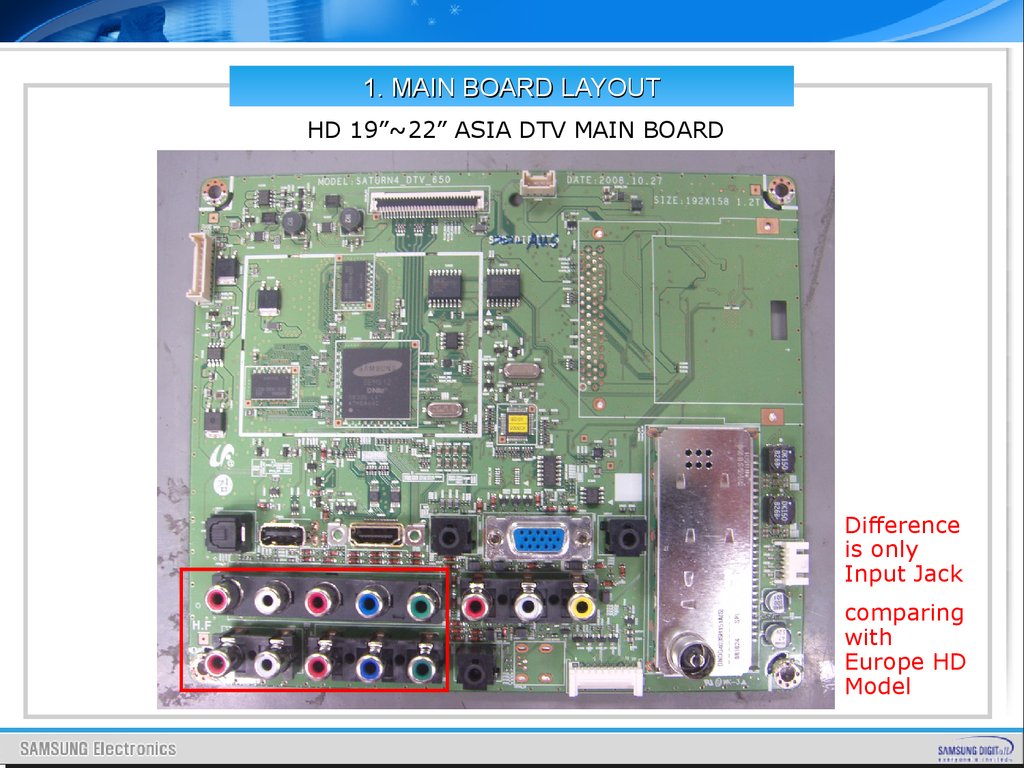
1. MAIN BOARD LAYOUTHD 19”~22” ASIA DTV MAIN BOARD
Difference
is only
Input Jack
comparing
with
Europe HD
Model
57.
Ⅲ. Board description2. MAIN BOARD PIN CHARACTERISTIC
Main Board power supply : 26” ~ 46”
PIN
1
2
3
4
5
6
7
8
9
10
11
12
13
14
NAME
HSYN
C
SW_POWER
GND
A5V
GND
GND
B13VS
B13VS
GND
GND
GND
GND
B5V
B5V
PIN
15
16
17
18
19
20
21
22
23
24
25
26
NAME
B5V
B5V
GND
GND
GND
B13V
B13V
B13V
ANA_DIMMIN
G
SW_INVERTER
GND
PWM_DIMMING
PIN
27
28
29
30
NAME
NC
LAMP_DETEC
T
NC
NC
Main Board power supply : B350 26” ~ 32”
12
13
14
15
16
SW_INV
Dimming
LAMP_DET
GND
GND
PIN
1
2
3
4
5
6
7
8
9
NAME
SW_POWER
A13V
GND
GND
GND
A5V
A5V
SW_POWER
SW_INVERTER
Main Board power supply : 19” ~ 22”
PIN
1
2
3
4
5
6
7
8
9
10
11
NAME
SW_POWE
R
A5V
GND
A13V
GND
GND
A5V
A5V
GND
A13V
A11V
SPEAKER CONNECTOR
PIN
1
2
3
4
NAME
L- OUT
L+ OUT
R- OUT
R+ OUT
58.
Ⅲ. Board descriptionDimming
Analog Dimming ; Current Amplitude Control
PWM Dimming
1. I-PWM ; DC(0~3.3V) signal
2. E-PWM ; Pulse signal
ON/OFF
①
I-PWM
②
E-PWM
③
GND
④
DET_5V
⑤
-
I-PWM
(0~3.3v)
+
PWM IC
LX1691A
(4 pin DD_CLK)
COMP
.
OSC
Sync
Sync + duty
Sync Ctr
Internal PWM
External
PWM
59.
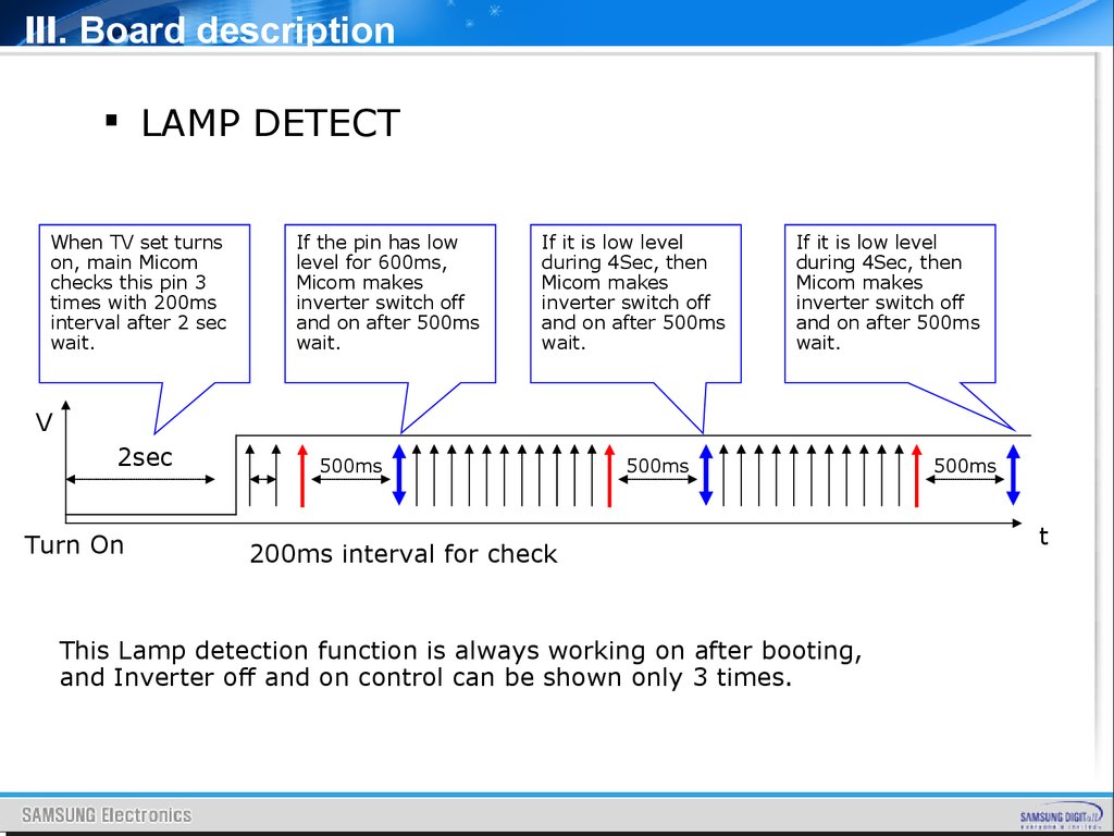
Ⅲ. Board descriptionLAMP DETECT
When TV set turns
on, main Micom
checks this pin 3
times with 200ms
interval after 2 sec
wait.
If the pin has low
level for 600ms,
Micom makes
inverter switch off
and on after 500ms
wait.
If it is low level
during 4Sec, then
Micom makes
inverter switch off
and on after 500ms
wait.
If it is low level
during 4Sec, then
Micom makes
inverter switch off
and on after 500ms
wait.
V
2sec
Turn On
500ms
500ms
200ms interval for check
This Lamp detection function is always working on after booting,
and Inverter off and on control can be shown only 3 times.
500ms
t
60.
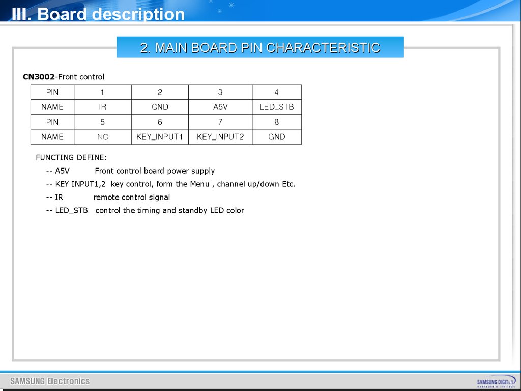
Ⅲ. Board description2. MAIN BOARD PIN CHARACTERISTIC
CN3002-Front control
PIN
1
2
3
4
NAME
IR
GND
A5V
LED_STB
PIN
5
6
7
8
NAME
NC
KEY_INPUT1
KEY_INPUT2
GND
FUNCTING DEFINE:
-- A5V
Front control board power supply
-- KEY INPUT1,2 key control, form the Menu , channel up/down Etc.
-- IR
-- LED_STB
remote control signal
control the timing and standby LED color
61.
Ⅲ. Board description2. MAIN BOARD PIN CHARACTERISTIC
CN6001_T - HD LVDS Digital Signal
PIN
1
2
3
4
5
6
NAME
PANEL_VCC
PANEL_VCC
PANEL_VCC
PANEL_VCC
PANEL_VCC
NC
PIN
7
8
9
10
11
12
NAME
GND
GND
RESET_TCON
GND
NC
GND
PIN
13
14
15
16
17
18
NAME
LVDS_TX3+
LVDS_TX3-
GND
LVDS_TXCLK+
LVDS_TXCLK-
GND
PIN
19
20
21
22
23
24
NAME
LVDS_TX2+
LVDS_TX2-
GND
LVDS_TX1+
LVDS_TX1-
GND
PIN
25
26
27
28
29
30
NAME
LVDS_TX0+
LVDS_TX0-
GND
SDA_TCON
SCL_TCON
WPN
FANET: Reads the T-CON BD EEPROM
Reduces the tact time including W/B,
F/Option setting and Protects service error
62.
Ⅲ. Board description1.Sequence Spec_ Power
Rising time _V = 0.9* V _max
AC 220V On
(Phase :0 도 )
Stand By
+5V
Power_ On
A
B
+5V
+13V
(+ 5V / +13V )
C
There is no spec about
Which voltage is faster.
D
Inverter_ On
Lamp
Current
Spec
MIN (msec)
MAX (msec)
A
100
1200
B
10
500
C
0.01
20m
D
10
300
63.
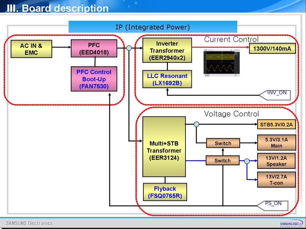
Ⅲ. Board descriptionIP (Integrated Power)
AC IN &
EMC
PFC
(EED4018)
Inverter
Transformer
(EER2940x2)
PFC Control
Boot-Up
(FAN7530)
LLC Resonant
(LX1692B)
Current Control
1300V/140mA
INV_ON
Voltage Control
STB5.3V/0.2A
Multi+STB
Transformer
(EER3124)
Flyback
(FSQ0765R)
Switch
5.3V/3.1A
Main
Switch
13V/1.2A
Speaker
13V/2.7A
T-con
PS_ON
64.
Ⅲ. Board description3. IP BOARD INPUT CHARCTERISTIC
3. INPUT CHARACTERISTICS
3.1 INPUT VOLTAGE RANGE 90Vac TO 264Vac , SINGLE PHASE.
NORMAL VOLTAGE: 100-240Vac
3.2 INPUT FREQUENCY RANGE 47Hz TO 63Hz.
NORMAL FREQUENCY: 50-60Hz
3.3 MAX INPUT AC CURRENT 2.0Arms @90VAC.
3.4 INRUSH CURRENT PEAK INRUSH CURRENT AT ANY ALLOWABLE OPERATING
TEMPERATURE SHALL NOT OPEN LINE FUSE, RECIFIER DIODE
OR CAUSE PERMANENT DAMAGE TO THE SUPPLY.
3.5 DPMS DISSAPATION LESS THAN 0.9 WATT AT 5V/40mA, AT 230Vac/60Hz.
OR NO LOAD 0.5W MAX AT 230Vac/60Hz
65.
Ⅲ. Board description4. POWER OUTPUT CHARACTERISTIC
4. POWER OUTPUT CHARACTERISTICS
4.1 . Power Output Voltage
Min ( Vrms )
NOM ( Vrms )
Max ( Vrms )
+13Vdc
12.5
13.0
13.2
+5.3Vdc
5.03
5.3
5.56
+5.3VSBdc
5.03
5.3
5.56
Parameter
The output voltage is measured at the connector at the output end of the
cable.
4.2 . Power Output Current
Min ( Arms )
NOM ( Arms )
Max ( Arms )
+13Vdc
0.2
-
1.6
+5.3Vdc
0.5
-
2
+5.3VSBdc
0.01
-
0.6
Parameter
The minimum and maximum continuous output current are listed in this section
66.
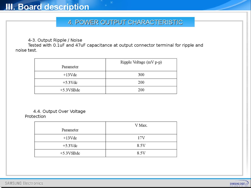
Ⅲ. Board description4. POWER OUTPUT CHARACTERISTIC
4-3. Output Ripple / Noise
Tested with 0.1uF and 47uF capacitance at output connector terminal for ripple and
noise test.
Ripple Voltage (mV p-p)
Parameter
+13Vdc
300
+5.3Vdc
200
+5.3VSBdc
200
4.4. Output Over Voltage
Protection
V Max.
Parameter
+13Vdc
17V
+5.3Vdc
8.5V
+5.3VSBdc
8.5V
67.
Ⅲ. Board description4. POWER OUTPUT CHARACTERISTIC
4.5. Output Over Current Protection
Parameter
A Min.
+13Vdc
2.5A
+5.3Vdc
2.8A
+5.3VSBdc
1.5A
4.6. Output Power And Turn-on Delay
The turn-on delay from application of AC input power to the establishment of rated DC
power
voltage should not exceed 3 seconds@100Vac under any conditions at CC mode test .
4.7. Output Voltage Hold-up Time
When the power supply is operated at 100% of maximum continuous output load , the
minimum
output hold-up time after loss of input power shall be 20.0mS for AC input voltage
(100Vac /
60Hz ) and at 45-degrees cut angle
68.
Ⅲ. Board description5. INVERTER OUTPUT CHARACTERISTIC
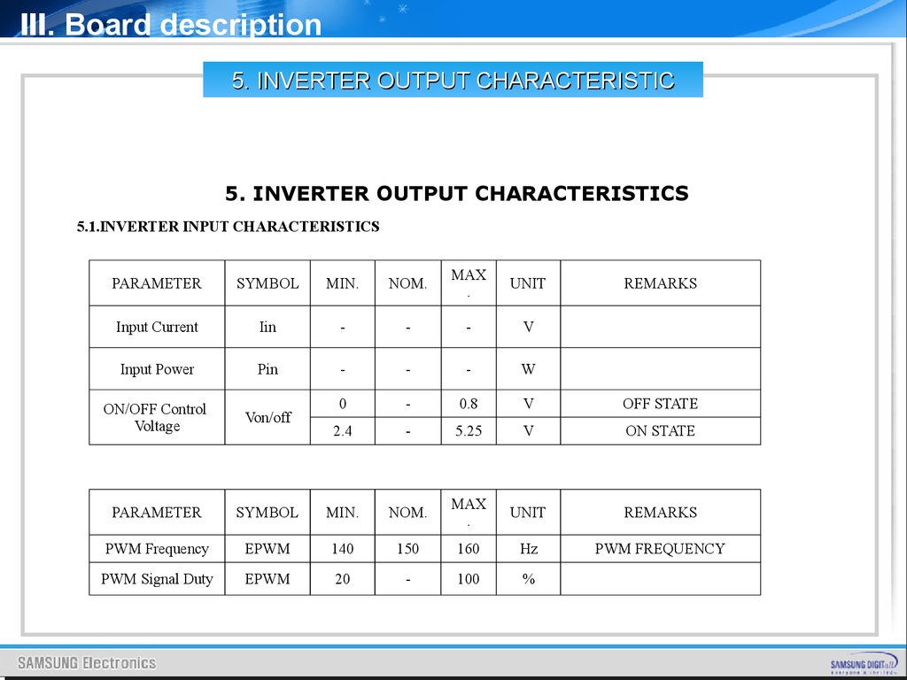
5. INVERTER OUTPUT CHARACTERISTICS
5.1.INVERTER INPUT CHARACTERISTICS
PARAMETER
SYMBOL
MIN.
NOM.
MAX
.
UNIT
Input Current
Iin
-
-
-
V
Input Power
Pin
-
-
-
W
ON/OFF Control
Voltage
Von/off
0
-
0.8
V
OFF STATE
2.4
-
5.25
V
ON STATE
PARAMETER
SYMBOL
MIN.
NOM.
MAX
.
UNIT
REMARKS
PWM Frequency
EPWM
140
150
160
Hz
PWM FREQUENCY
PWM Signal Duty
EPWM
20
-
100
%
REMARKS
69.
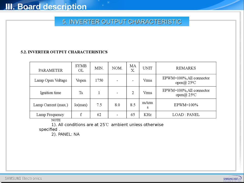
Ⅲ. Board description5. INVERTER OUTPUT CHARACTERISTIC
5.2. INVERTER OUTPUT CHARACTERISTICS
PARAMETER
SYMB
OL
MIN.
NOM.
MA
X.
UNIT
REMARKS
Lamp Open Voltage
Vopen
1750
-
-
Vrms
EPWM=100%,All connector
open@ 250C
Ignition time
Ts
1
-
2
Vrms
EPWM=100%,All connector
open@ 250C
Lamp Current (max.)
Io(max)
7.5
8.0
8.5
mArm
s
EPWM=100%
Lamp Frequency
f
62
-
65
KHz
LOAD : PANEL
NOTE
1). All conditions are at 25℃ ambient unless otherwise
specified .
2). PANEL: NA
70.
Ⅲ. Board description6. ENVIRONMENTAL CHARACTERISTIC
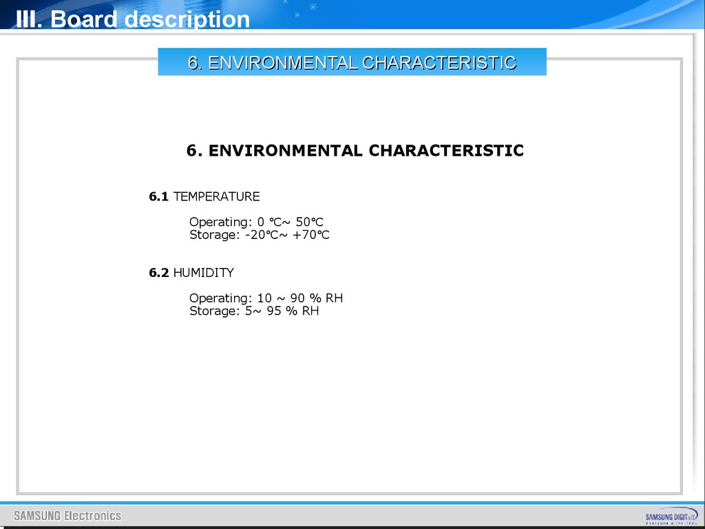
6. ENVIRONMENTAL CHARACTERISTIC
6.1 TEMPERATURE
Operating: 0 ℃~ 50℃
Storage: -20℃~ +70℃
6.2 HUMIDITY
Operating: 10 ~ 90 % RH
Storage: 5~ 95 % RH
71.
Ⅲ. Board description7. Power BOARD LAYOUT
19” SMPS Board
DC
Regulation
Inverter
Transformer
AC INPUT
72.
Ⅲ. Board description7. POWER BOARD LAYOUT
22” SMPS Board
Inverter
DC
Regulation
Transformer
AC INPUT
73.
Ⅲ. Board description7. POWER BOARD LAYOUT
26” IP Board
Inverter
Supply Part
PFC Coil
DC
Regulation
AC INPUT
74.
Ⅲ. Board description7. POWER BOARD LAYOUT
32” IP Board
Inverter
Supply Part
PFC Coil
DC
Regulation
AC INPUT
75.
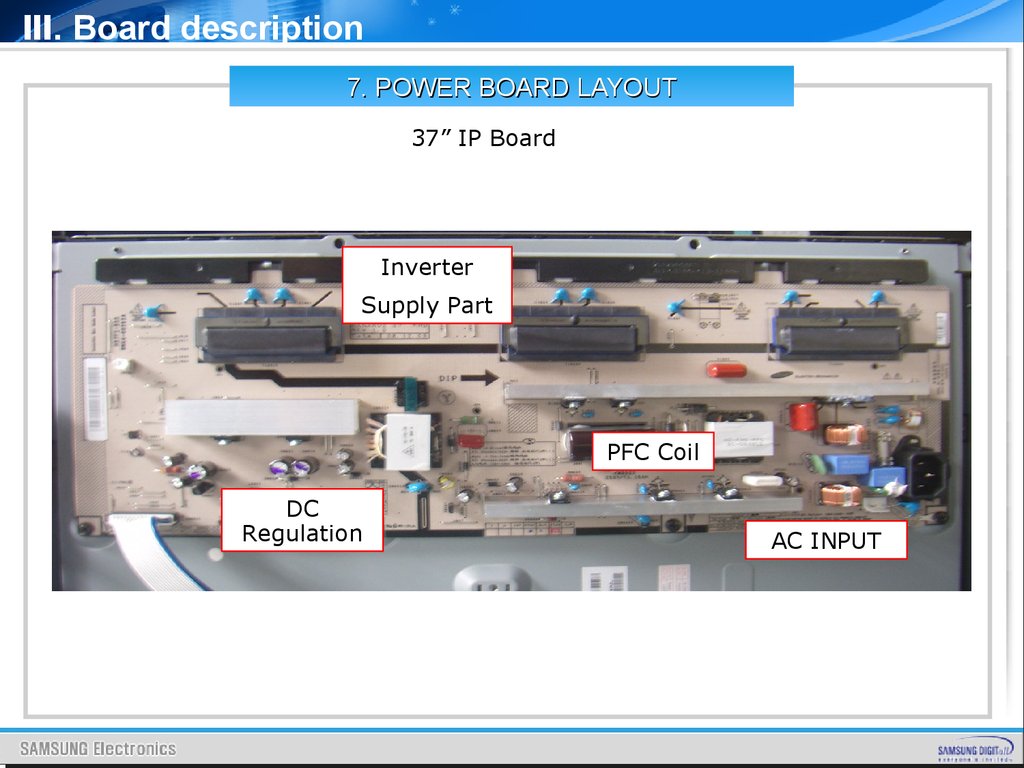
Ⅲ. Board description7. POWER BOARD LAYOUT
37” IP Board
Inverter
Supply Part
PFC Coil
DC
Regulation
AC INPUT
76.
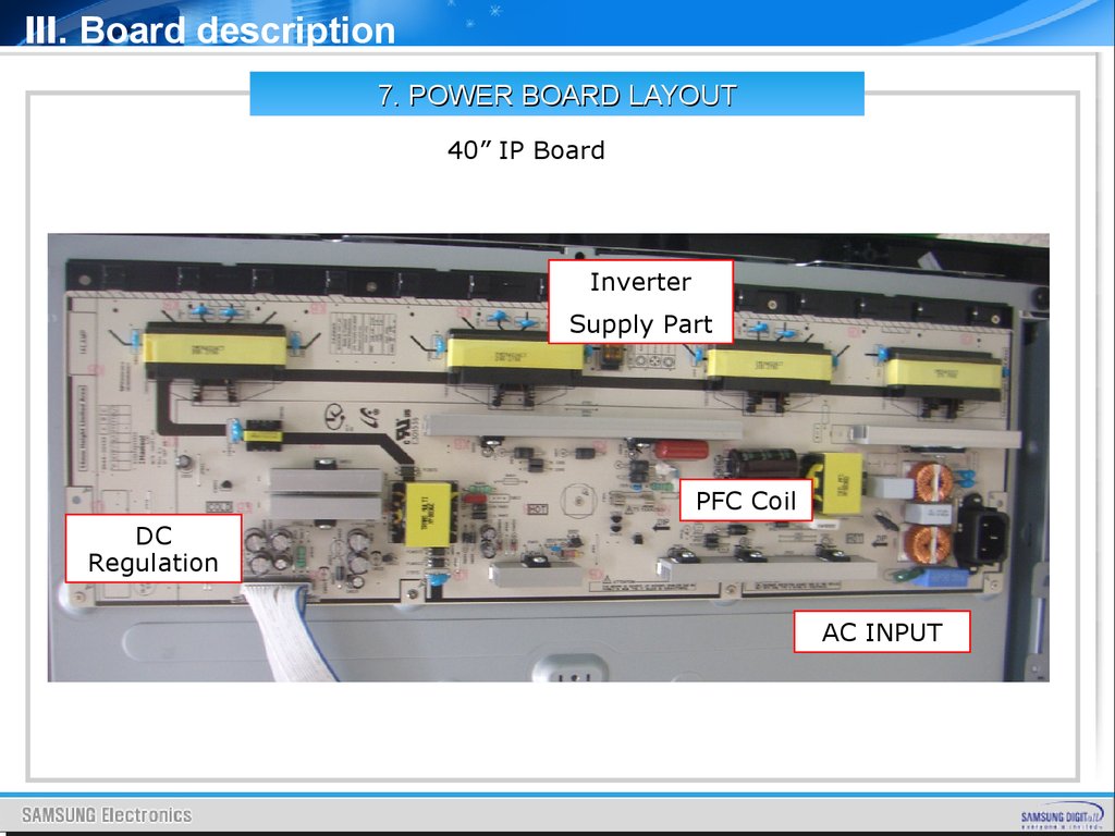
Ⅲ. Board description7. POWER BOARD LAYOUT
40” IP Board
Inverter
Supply Part
PFC Coil
DC
Regulation
AC INPUT
77.
Ⅲ. Board description7. POWER BOARD LAYOUT
46” SMPS Board
Inverter
Supply Part
DC
Regulation
PFC Coil
AC INPUT
78.
Ⅲ. Board description8. IP BOARD PIN CHARACTERISTIC
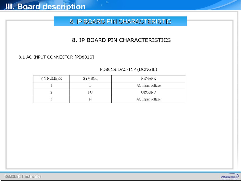
8. IP BOARD PIN CHARACTERISTICS
8.1 AC INPUT CONNECTOR [PD801S]
PD801S:DAC-11P (DONGIL)
PIN NUMBER
SYMBOL
REMARK
1
L
AC Input voltage
2
FG
GROUND
3
N
AC Input voltage
79.
Ⅲ. Board description8. IP BOARD PIN CHARACTERISTIC
8.2 POWER OUTPUT CONNECOTR PIN ASSIGNMENT[CNM801]
CN802:SMW200-30C(YEONHO)
PIN NUMBER
SYMBOL
REMARK
1
POWER ON/OFF
POWER SUPPLY ON/OFF
2
H-Sync
NC
3
5VSB
4,5,6
GND
7,8
13V(Sound)
9,10,11,12
GND
13,14,15,16
5.3V
17,18
GND
19
13V(MAIN)
20
GND
21,22
13V(MAIN)
+13V DC OUTPUT
23
Inverter ON/OFF
BLU ON/OFF
24
IPWM
NC
25
EPWM
20~100%
26
GND
S-GND
27
LAMP_DET
ERROR (Normal: Hi ; Abnormal :Low)
28,29,30
NC
NC
+13V DC OUTPUT
+5.3V DC OUTPUT
+13V DC OUTPUT
80.
Ⅲ. Board description8. IP BOARD PIN CHARACTERISTIC
Test Condition of the circuit [Jig Test]
81.
Ⅲ. Board description8. IP BOARD PIN CHARACTERISTIC
GENERAL REQUIREMENT OF WORLDWIDE STANDARD
1. MEET SAFETY REQUIRMENT.
UL60065, CSA C22.2 NO.60065, IEC 60065 FOR UL,CUL,CB,EK.
2. IMMUNITY TEST (EN55024)
- IEC61000-4-2 ELECTROSTATIC DISCHARGE LMMUNITY TEST (ESD) Level 4 Criterion B
(1) AIR DISCHARGE TEST(WITH SYSTEM) ±2KV, ±4KV, ±8KV, ±15KV.
(2) CONTACT DISCHARGE TEST(WITH SYSTEM) ±2KV, ±4KV, ±8KV.
- IEC61000-4-3 Radio Frequency Electromagnetic Field Immunity Test (RS): Level 2,
criterion A. (WITH SYSTEM)
- IEC61000-4-4 Electrical Fast Transient/Burst Immunity Test (EFT) Level 2 1KV/5KHz
on AC power port for 1 minute, criterion B. (WITH SYSTEM)
- IEC61000-4-5 Surge Immunity Test (PLD) (WITH SYSTEM)
(1) L to N 1.0KV/1.2*50uS, criterion B.
(2) L/N to FG 2.0KV/1.2*50uS, criterion B.
- IEC61000-4-6 Conducted Disturbances Induced by Radio-Frequency Field Immunity
Test (CS) Level 2 criterion A. (WITH SYSTEM)
- IEC61000-4-11 Voltage Dips and Voltage Interruptions Immunity Test
(1) Criterion B for > 95%, 0.5period Voltage Dips.
(2) Criterion C for > 30%, 25period Voltage Dips;> 95%, 250period Voltage Interruptions.
82.
IV. DisassemblyDISASSEMBLY
83.
IV. Disassembly84.
IV. Disassembly85.
IV. Disassembly86.
IV. Disassembly87.
V. Trouble ShootingCONTENTS
I.
Power Trouble Shooting
II.
Analog Part
III.
Digital Part
IV.
Sound Part
V.
Flow Chart & Waveforms
VI.
White Balance
88.
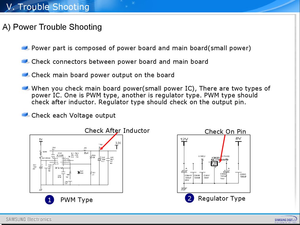
V. Trouble ShootingA) Power Trouble Shooting
Power part is composed of power board and main board(small power)
Check connectors between power board and main board
Check main board power output on the board
When you check main board power(small power IC), There are two types of
power IC. One is PWM type, another is regulator type. PWM type should
check after inductor. Regulator type should check on the output pin.
Check each Voltage output
Check After Inductor
1
PWM Type
Check On Pin
2
Regulator Type
89.
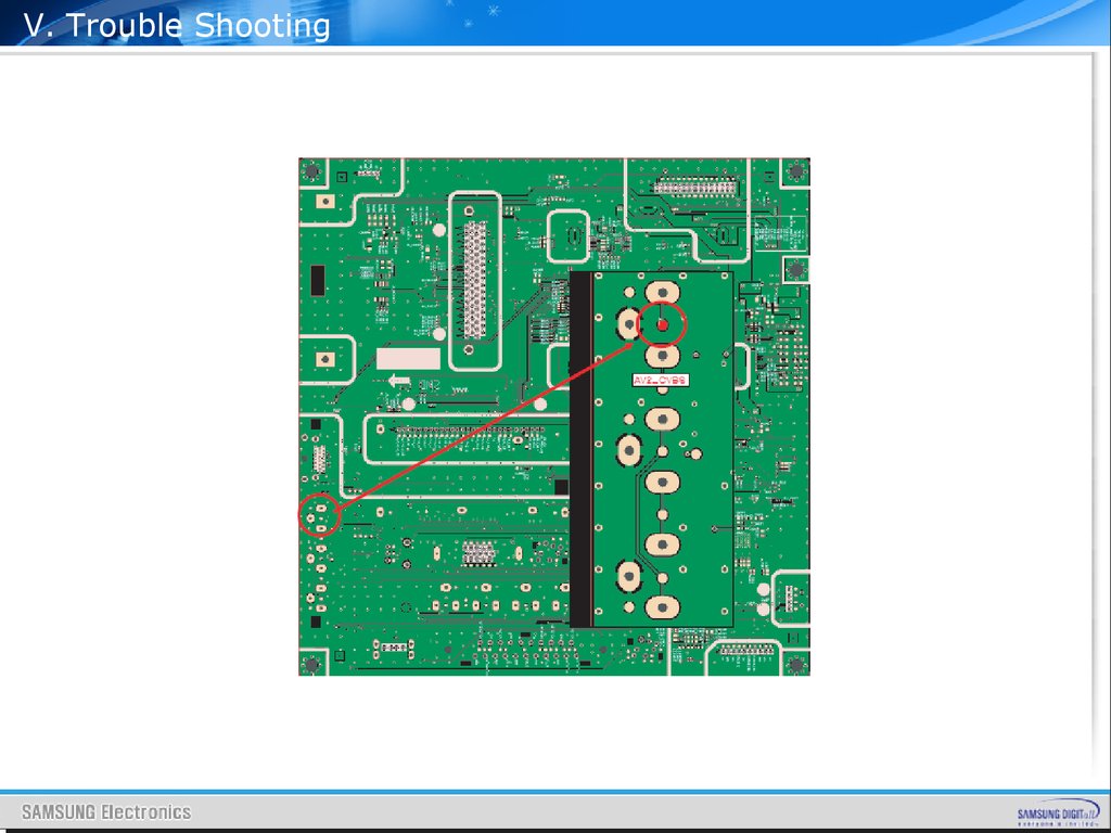
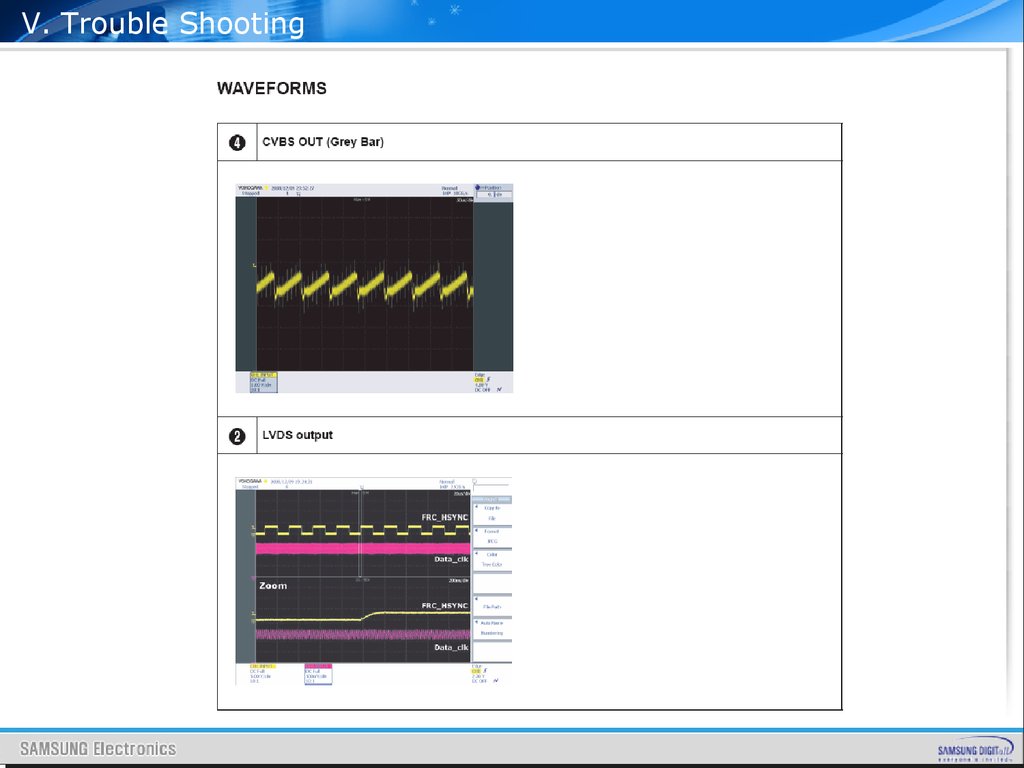
V. Trouble ShootingB) Analog Part
It is easy to check analog video signal than digital video signal
Use reference signal input ( EX. 16 Gray)
Check Signal Level and sync
Check Signal path until input of Video decoder
( Tuner → Switch → Video Decoder, AV Connecter → Switch → Video
Decoder, Scart → Switch → Video Decoder )
Gray Level
H-sync
16 Gray Patten
16 Gray Wave Form
90.
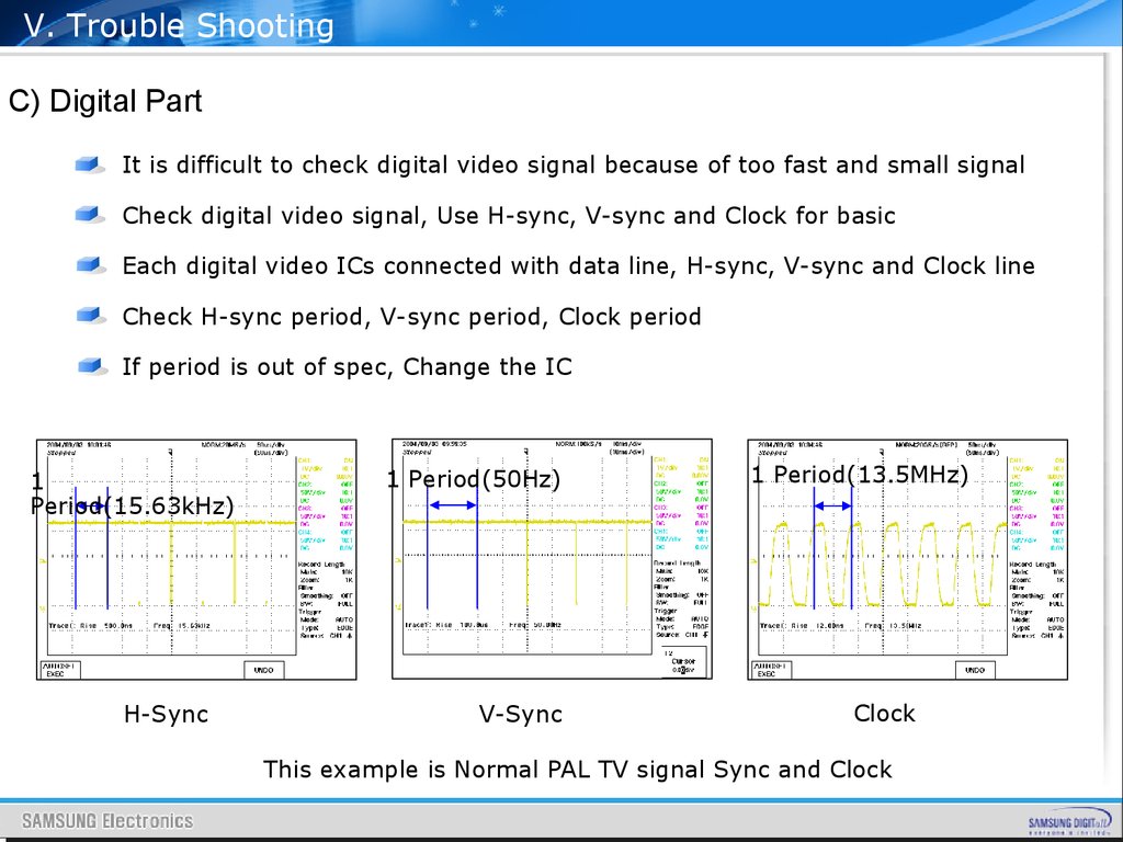
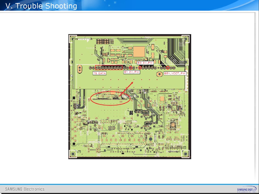
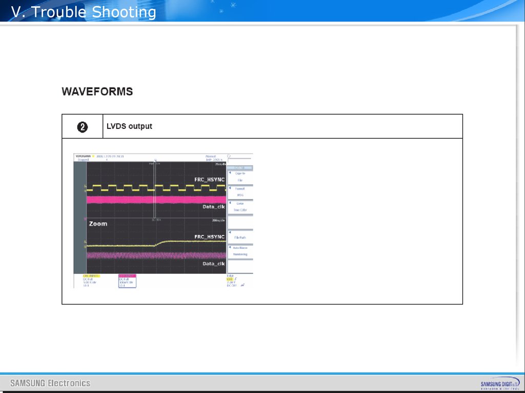
V. Trouble ShootingC) Digital Part
It is difficult to check digital video signal because of too fast and small signal
Check digital video signal, Use H-sync, V-sync and Clock for basic
Each digital video ICs connected with data line, H-sync, V-sync and Clock line
Check H-sync period, V-sync period, Clock period
If period is out of spec, Change the IC
1
Period(15.63kHz)
H-Sync
1 Period(50Hz)
V-Sync
1 Period(13.5MHz)
Clock
This example is Normal PAL TV signal Sync and Clock
91.
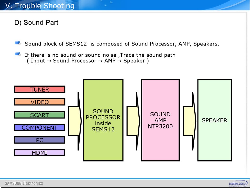
V. Trouble ShootingD) Sound Part
Sound block of SEMS12 is composed of Sound Processor, AMP, Speakers.
If there is no sound or sound noise ,Trace the sound path
( Input → Sound Processor → AMP → Speaker )
TUNER
VIDEO
SCART
COMPONENT
PC
HDMI
SOUND
PROCESSOR
inside
SEMS12
SOUND
AMP
NTP3200
SPEAKER
92.
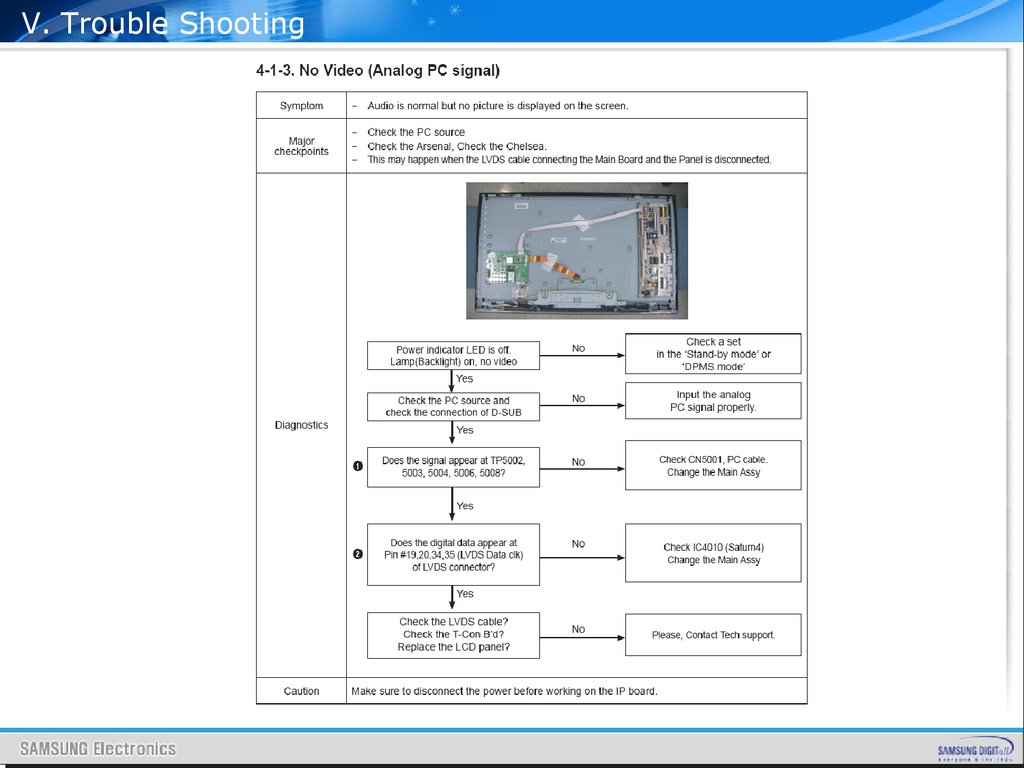
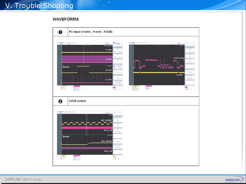
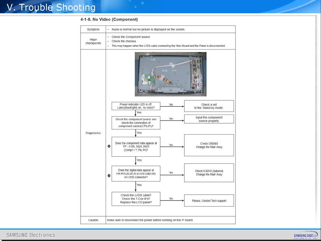
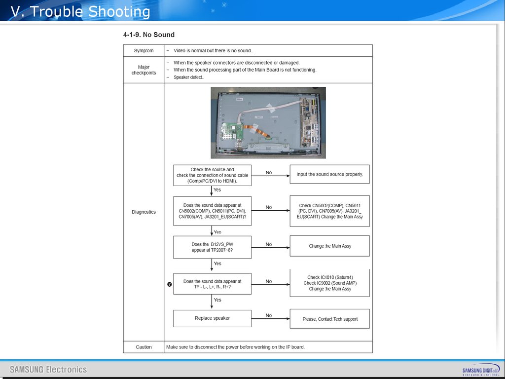
V. Trouble Shooting93.
V. Trouble Shooting94.
V. Trouble Shooting95.
V. Trouble Shooting96.
V. Trouble Shooting97.
V. Trouble Shooting98.
V. Trouble Shooting99.
V. Trouble Shooting100.
V. Trouble Shooting101.
V. Trouble Shooting102.
V. Trouble Shooting103.
V. Trouble Shooting104.
V. Trouble Shooting105.
V. Trouble Shooting106.
V. Trouble Shooting107.
V. Trouble Shooting108.
V. Trouble Shooting109.
V. Trouble Shooting110.
V. Trouble Shooting111.
V. Trouble Shooting112.
V. Trouble Shooting113.
V. Trouble Shooting114.
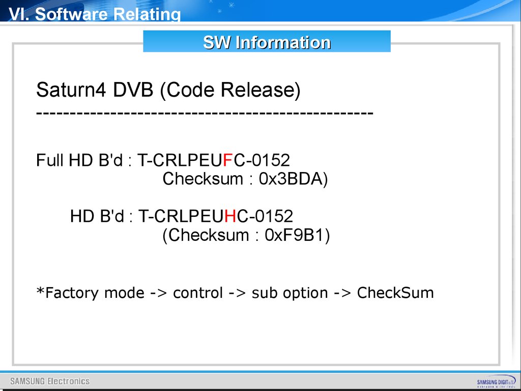
VI. Software RelatingSW Information
Saturn4 DVB (Code Release)
-------------------------------------------------Full HD B'd : T-CRLPEUFC-0152
Checksum : 0x3BDA)
HD B'd : T-CRLPEUHC-0152
(Checksum : 0xF9B1)
*Factory mode -> control -> sub option -> CheckSum
115.
VI. Software RelatingSW upgrade
*Please unzip this file to your HDD
*Copy the directory to root of USB memory
and follow next page actions
*The folder has these files
116.
VI. Software RelatingSW upgrade
117.
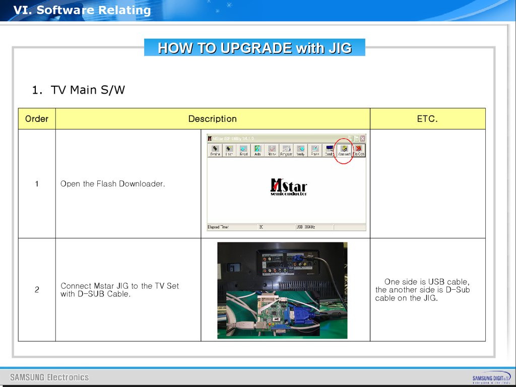
VI. Software RelatingHOW TO UPGRADE with JIG
1. TV Main S/W
Order
Description
ETC.
1
Open the Flash Downloader.
2
Connect Mstar JIG to the TV Set
with D-SUB Cable.
One side is USB cable,
the another side is D-Sub
cable on the JIG.
118.
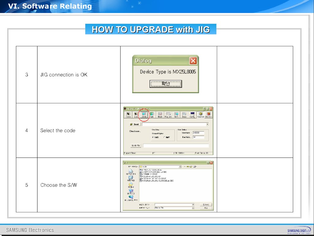
VI. Software RelatingHOW TO UPGRADE with JIG
3
JIG connection is OK
4
Select the code
5
Choose the S/W
119.
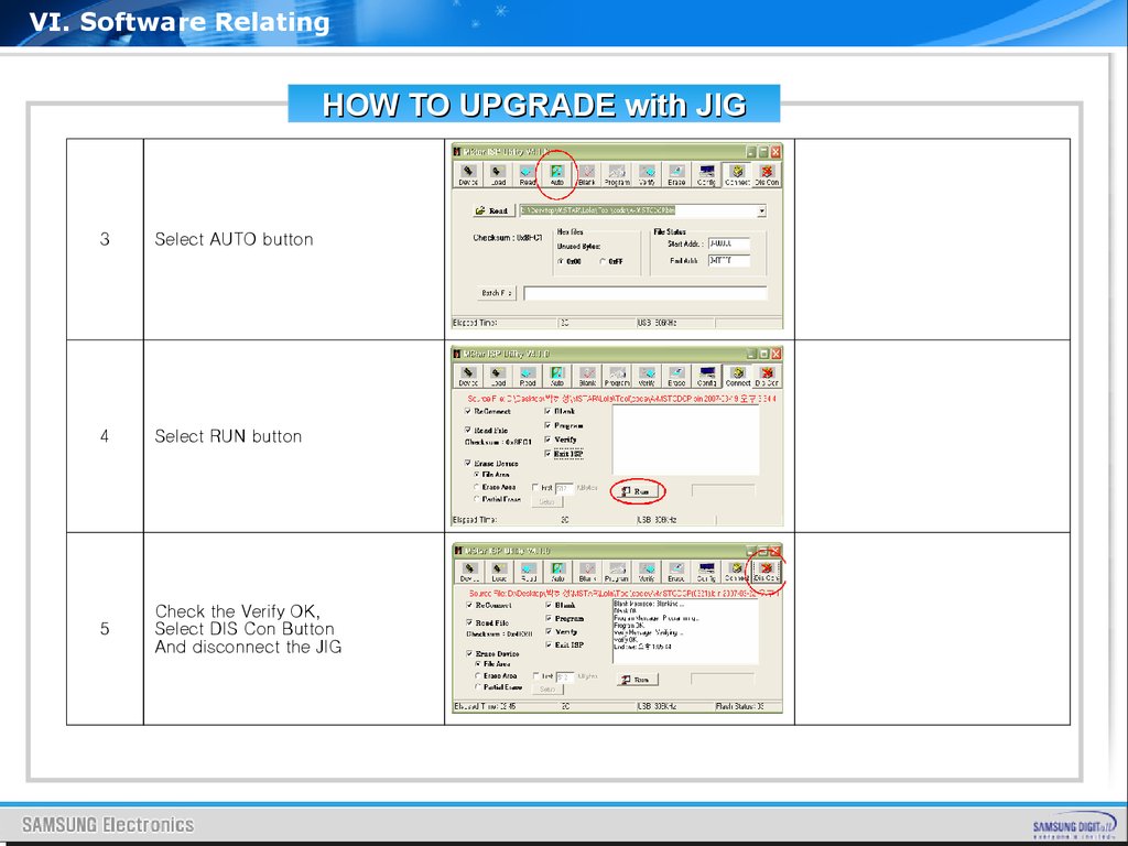
VI. Software RelatingHOW TO UPGRADE with JIG
3
Select AUTO button
4
Select RUN button
5
Check the Verify OK,
Select DIS Con Button
And disconnect the JIG
120.
Appendix1. Feature & Specification
2. PC timing of FHD & HD
3. Comparison of User key pad
4. Signal Flows Information
5. IP Schematic Diagram
121.
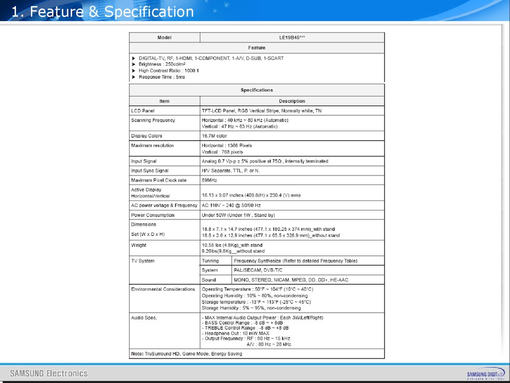
1. Feature & Specification122.
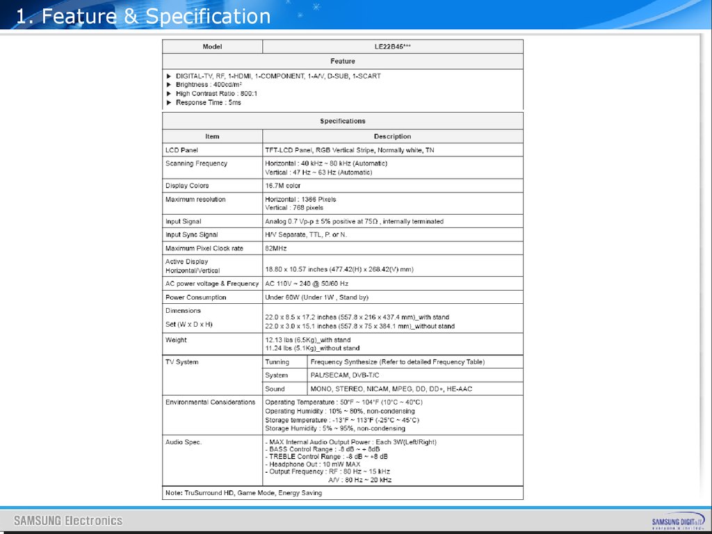
1. Feature & Specification123.
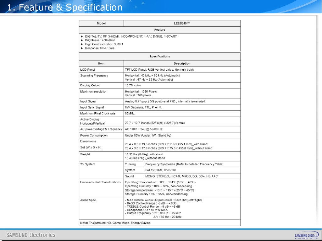
1. Feature & Specification124.
1. Feature & Specification125.
1. Feature & Specification126.
1. Feature & Specification127.
1. Feature & Specification128.
1. Feature & Specification129.
2. PC TimingDisplay Mode
New FHD TV
No
Originator
Resolution
Horizontal
Frequency
(kHz)
Vertical Frequency
(Hz)
Pixel Clock
(MHz)
Sync Polarity
(H/V)
PC
HDMI
1
IBM
640 x 350
70Hz
O
O
31.469
70.086
25.175
+/-
2
VESA DMT
640 x 480
60Hz
O
O
31.469
59.940
25.175
-/-
3
MAC
640 x 480
67Hz
O
O
35.000
66.667
30.240
-/-
72Hz
O
O
37.861
72.809
31.500
-/-
75Hz
O
O
37.500
75.000
31.500
-/-
4
VESA DMT
640 x 480
5
6
IBM
720 x 400
70Hz
O
O
31.469
70.087
28.322
-/+
7
VESA CVT
720 x 576
60Hz
O
O
35.910
59.950
32.750
-/+
8
VESA DMT
800 x 600
60Hz
O
O
37.879
60.317
40.000
+/+
72Hz
O
O
48.077
72.188
50.000
+/+
VESA DMT
800 x 600
75Hz
O
O
46.875
75.000
49.500
+/+
75Hz
O
O
49.726
74.551
57.284
-/-
60Hz
O
O
48.363
60.004
65.000
-/-
70Hz
O
O
56.476
70.069
75.000
-/-
9
10
11
MAC
832 x 624
VESA DMT
1024 x 768
12
13
14
VESA DMT
1024 x 768
75Hz
O
O
60.023
75.029
78.750
+/+
15
VESA CVT
1152 x 864
60Hz
O
O
53.783
59.959
81.750
-/+
16
VESA DMT
1152 x 864
75Hz
O
O
67.500
75.000
108.000
+/+
17
MAC
1152 x 870
75Hz
O
O
68.681
75.062
100.000
-/-
18
VESA CVT
60Hz
O
O
44.772
59.855
74.500
-/+
19
VESA GTF
70Hz
O
O
52.500
70.000
`
-/+
20
VESA CVT
75Hz
O
O
56.456
74.777
95.750
-/+
60Hz
O
O
49.702
59.810
83.500
-/+
75Hz
O
O
62.795
74.934
106.500
-/+
1280 x 720
1280 x 720
21
1280 x 800
22
VESA DMT
23
1280 x 960
60Hz
O
O
60.000
60.000
108.000
+/+
24
VESA CVT
1280 x 960
75Hz
O
O
75.231
74.857
130.000
-/+
25
VESA DMT
1280 x 1024
60Hz
O
O
63.981
60.020
108.000
+/+
26
VESA GTF
1280 x 1024
70Hz
O
O
74.620
70.000
128.943
-/-
27
1280 x 1024
75Hz
O
O
79.976
75.025
135.000
+/+
28
1360 x 768
60Hz
O
O
47.712
60.015
85.500
+/+
60Hz
O
O
55.935
59.887
106.500
-/+
75Hz
O
O
70.635
74.984
136.750
-/+
1680 x 1050
60Hz
O
O
65.290
59.954
146.250
-/+
1600 x 1200
60Hz
O
O
75.000
60.000
162.000
+/+
29
VESA DMT
1440 x 900
30
31
32
VESA DMT
130.
2. PC TimingDisplay Mode
No
Originator
New HD TV
Resolution
PC
HDMI
Horizontal
Frequency
(kHz)
Vertical
Frequency
(Hz)
Pixel Clock
(MHz)
Sync
Polarity
(H/V)
1
IBM
640 x 350
70Hz
O
O
31.469
70.086
25.175
+/-
2
VESA DMT
640 x 480
60Hz
O
O
31.469
59.940
25.175
-/-
3
MAC
640 x 480
67Hz
O
O
35.000
66.667
30.240
-/-
VESA DMT
640 x 480
72Hz
O
O
37.861
72.809
31.500
-/-
75Hz
O
O
37.500
75.000
31.500
-/-
6
IBM
720 x 400
70Hz
O
O
31.469
70.087
28.322
-/+
7
VESA CVT
720 x 576
60Hz
O
O
35.910
59.950
32.750
-/+
8
VESA DMT
800 x 600
60Hz
O
O
37.879
60.317
40.000
+/+
VESA DMT
800 x 600
72Hz
O
O
48.077
72.188
50.000
+/+
75Hz
O
O
46.875
75.000
49.500
+/+
MAC
832 x 624
75Hz
O
O
49.726
74.551
57.284
-/-
VESA DMT
1024 x 768
60Hz
O
O
48.363
60.004
65.000
-/-
70Hz
O
O
56.476
70.069
75.000
-/-
14
VESA DMT
1024 x 768
75Hz
O
O
60.023
75.029
78.750
+/+
18
VESA CVT
60Hz
O
O
44.772
59.855
74.500
-/+
19
VESA GTF
70Hz
O
O
52.500
70.000
89.040
-/+
17
VESA CVT
1280 x 720
75Hz
O
O
56.456
74.777
95.750
-/+
18
VESA DMT
1360 x 768
60Hz
O
O
47.712
60.015
85.500
+/+
4
5
9
10
11
12
13
1280 x 720
131.
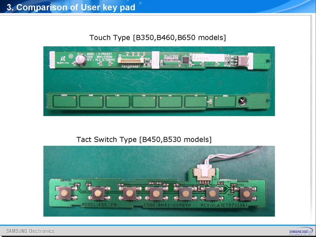
3. Comparison of User key padTouch Type [B350,B460,B650 models]
Tact Switch Type [B450,B530 models]
132.
4. Signal Flows InformationContents
1.
2.
3.
4.
5.
6.
7.
PC Input
Tuner Input
Component Input
HDMI Input
SCART Input
AV Input
SEMS12 Input & Output
-.AUDIO
-.CVBS & RGB Analog
-.HDMI
-.DDR
-.CI
-.LVDS Output
8. Sound AMP
133.
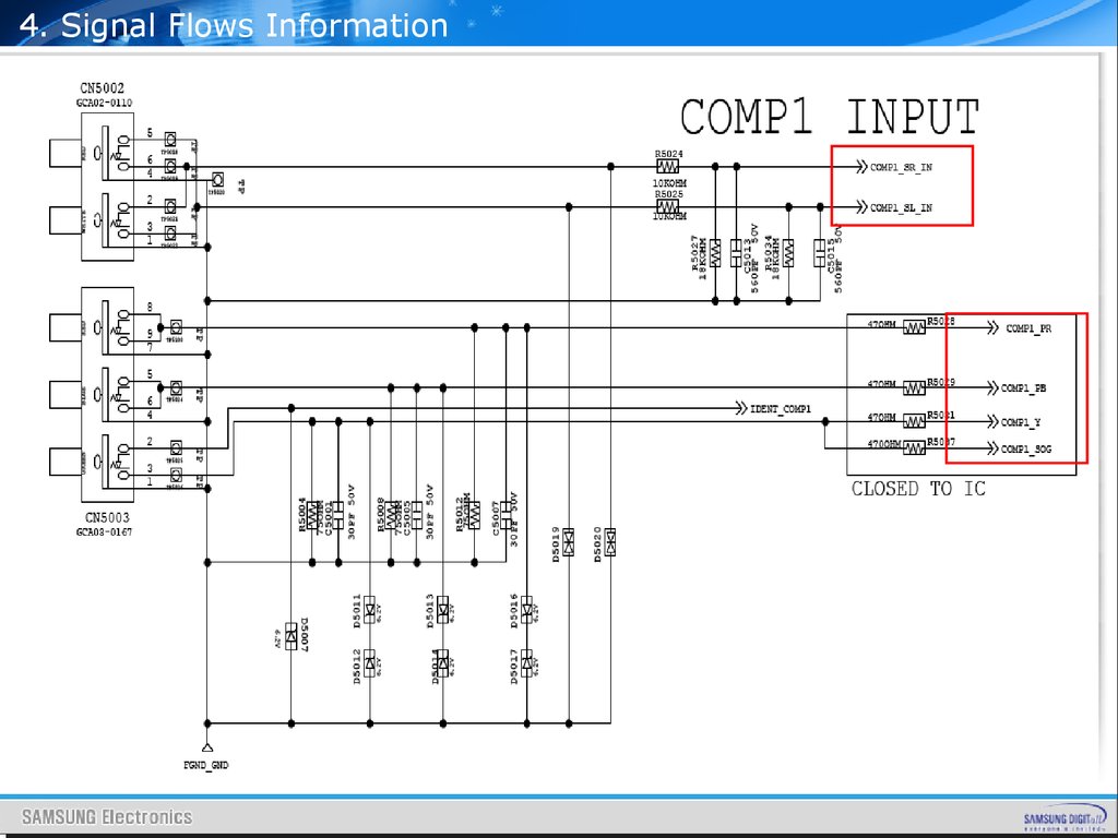
4. Signal Flows Information134.
4. Signal Flows Information135.
4. Signal Flows Information136.
4. Signal Flows Information137.
4. Signal Flows Information138.
4. Signal Flows Information139.
4. Signal Flows InformationTuner, AV, SCART,
COMPONENT ALL
SOUND INPUT
SIGNALS go into
SEMS12 directly,
there is no switch.
140.
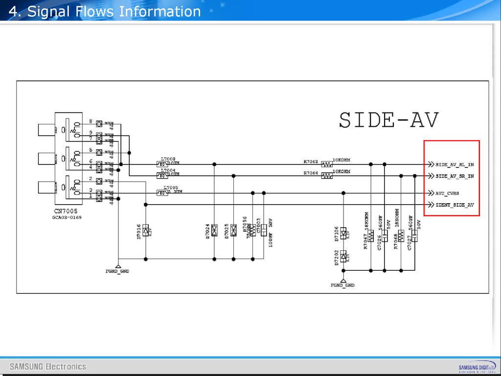
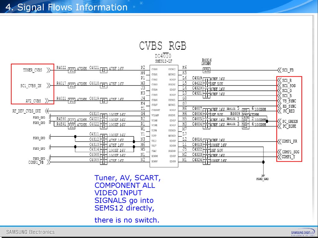
4. Signal Flows InformationTuner, AV, SCART,
COMPONENT ALL
VIDEO INPUT
SIGNALS go into
SEMS12 directly,
there is no switch.
141.
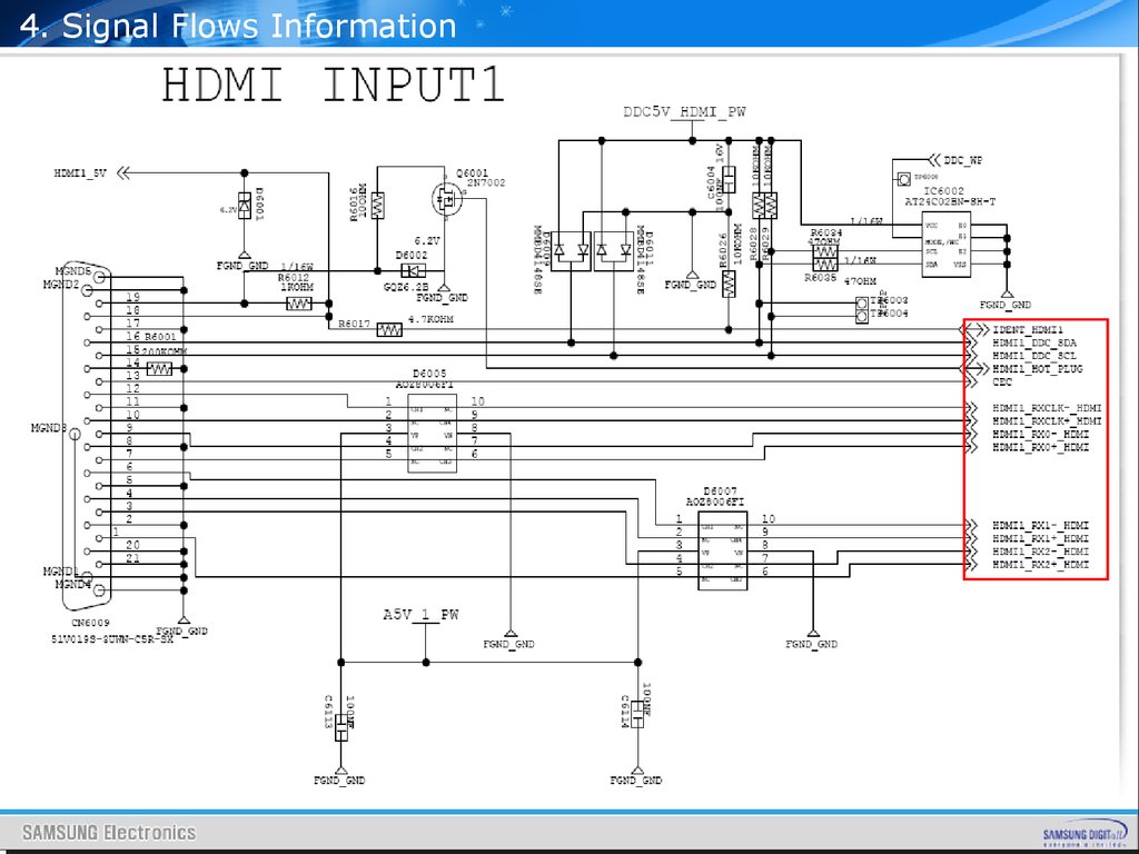
4. Signal Flows Information3 HDMI VIDEO INPUT SIGNALS go into SEMS12
directly, there is no switch.
142.
4. Signal Flows InformationDDR SIGNALS go into SEMS12 directly
143.
4. Signal Flows InformationCI SIGNALS go into SEMS12 directly
144.
4. Signal Flows InformationLVDS SIGNALS go into TCON BD directly
145.
4. Signal Flows InformationSOUND SIGNALS go into NTP3200
from SEMS12 and go out speakers
directly.
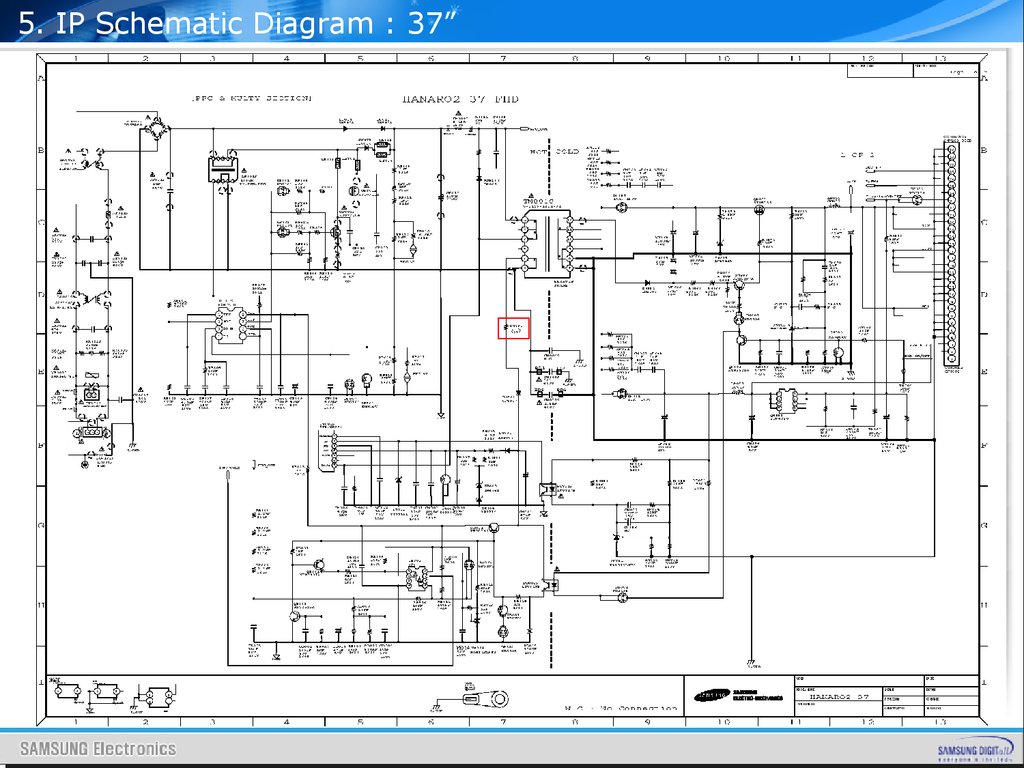
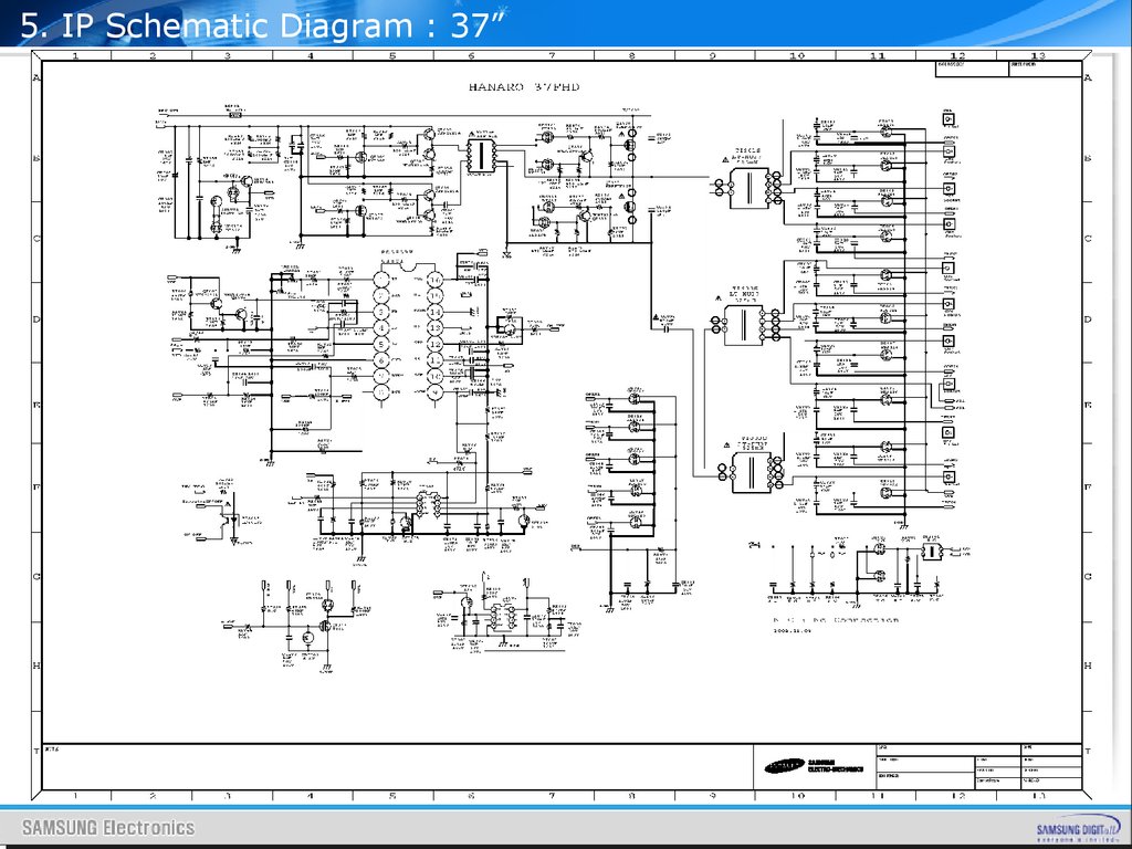
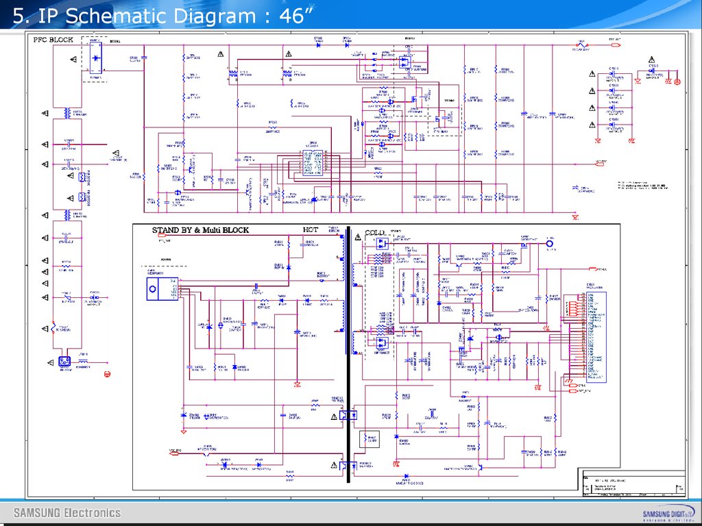
146.
5. IP Schematic DiagramContents
1. 32” IP Schematic Diagram
2. 37” IP Schematic Diagram
3. 40” IP Schematic Diagram
4. 46” IP Schematic Diagram