


 electronics
Similar presentations:


 Wireless Audio - Soundbar ’2017 SAMSUNG ELECTRONICS CO.,LTD. VD R&D GROUP")

Training book
1.
PDP Training Manual2.
Agenda1. P450 Training
2. Disassembly
3. Trouble shooting
4.Appendix
-. PC Timming
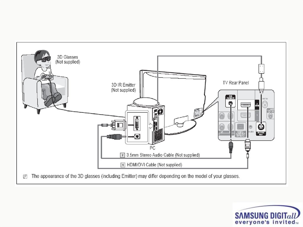
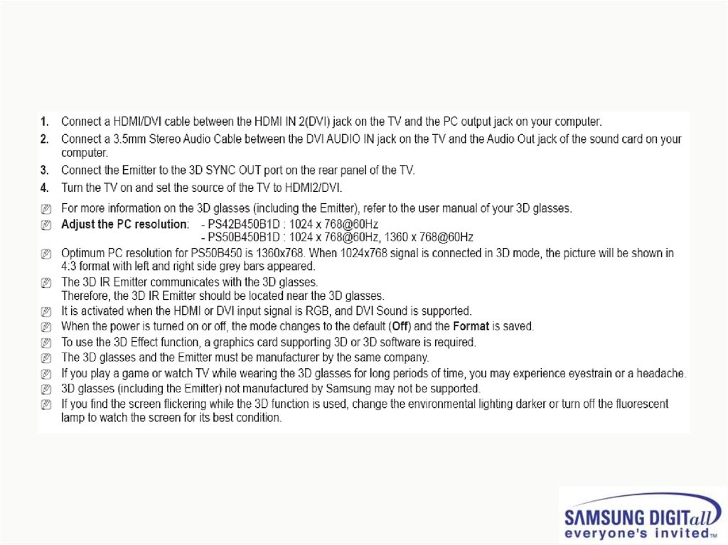
-. 3D Function
3.
1. PB450 Training4.
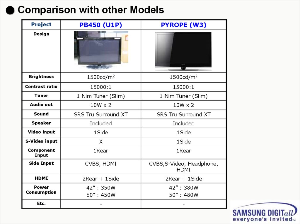
● Comparison with other ModelsPB450 (U1P)
PYROPE (W3)
Brightness
1500cd/m2
1500cd/m2
Contrast ratio
15000:1
15000:1
Tuner
1 Nim Tuner (Slim)
1 Nim Tuner (Slim)
Audio out
10W x 2
10W x 2
Sound
SRS Tru Surround XT
SRS Tru Surround XT
Speaker
Included
Included
Video input
1Side
1Side
S-Video input
X
1Side
Component
Input
1Rear
1Rear
Side Input
CVBS, HDMI
CVBS,S-Video, Headphone,
HDMI
HDMI
2Rear + 1Side
2Rear + 1Side
Power
Consumption
42” : 350W
50” : 450W
42” : 380W
50” : 480W
Etc.
-
-
Project
Design
5.
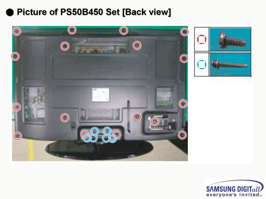
● Picture of PS50B450 Set [Back view]6.
● Picture of P450 42” U1P PDP Module [Back view]7.
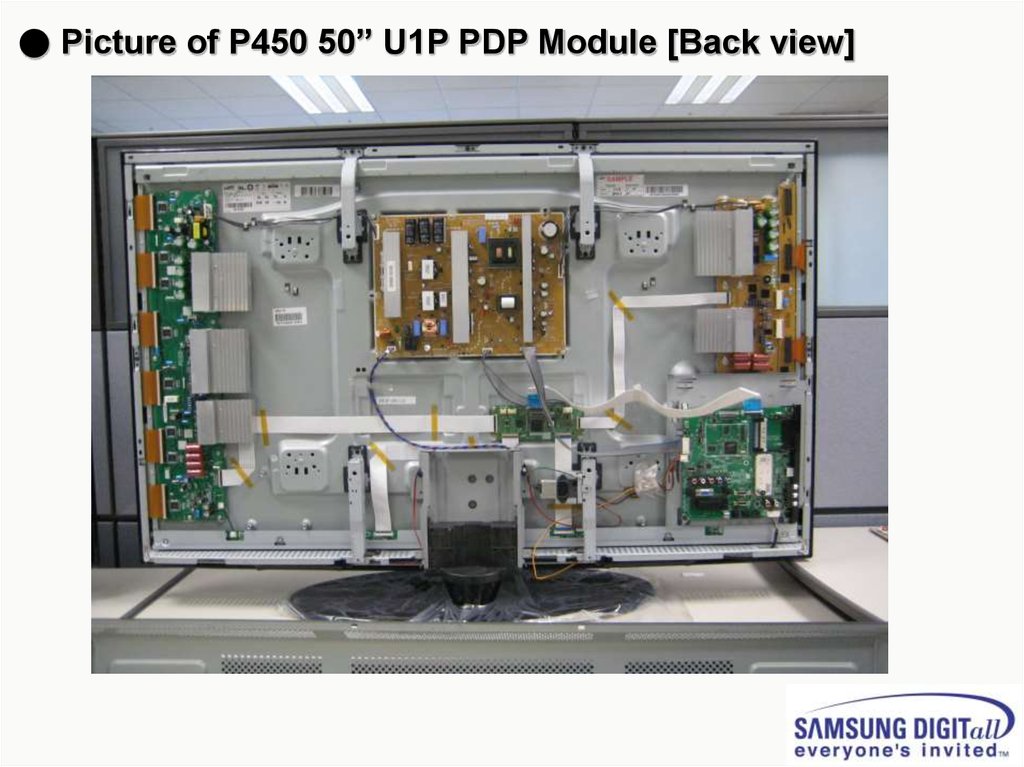
● Picture of P450 50” U1P PDP Module [Back view]8.
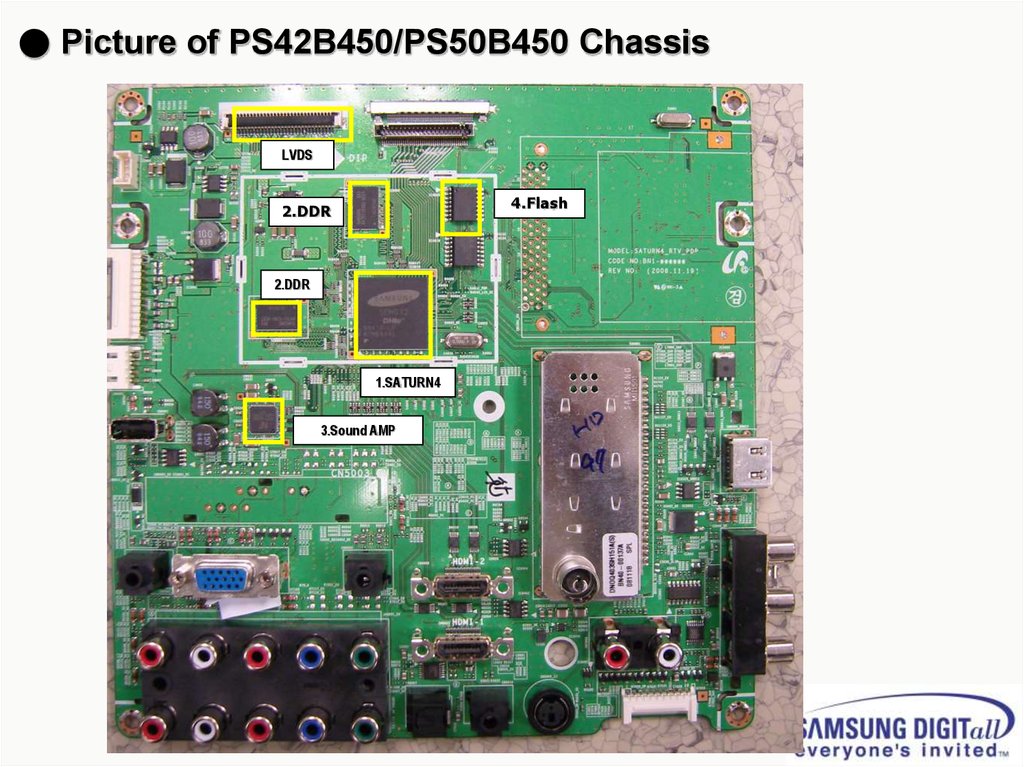
● Picture of PS42B450/PS50B450 ChassisLVDS
4.Flash
2.DDR
2.DDR
1.SATURN4
3.Sound AMP
9.
1IC5001
IC-LCD
CONTROLLER
SEMS01,LQFP,256P,30x30mm,PLASTIC,3.3V,2.2W,0to+70C,TR
2
IC6001
IC-VIDEO
PROCESS
S4LF119X01,PBGA,208P,17x17mm,PLASTIC,3.6V,0to+70C,TR,FBEx
3
IC7001
IC-DECODER
UPD61211GM-104-GAA-A,QFP,216P,24x24mm,PLASTIC,3.3V,700mA,0to+70C,TR
4
IC3001
IC-VIDEO
SWITCH
SiI9185CTU,QFP,80P,3.3V,0 to +70C,PLASTIC,TR
5
IC5201
IC-DDR
SDRAM
EM6A9160TS0A-5G,DDR
SDRAM,128Mbit,8Mx16,TSOP2,66P,22.22x10.16mm,5nS,2.375/2.625V,0to+70C,90mA
TR
6
IC7002
IC-DRAM
HYB25D256163CE,DDR,256Mbit,16Mx16Bit,TSOP,66P,22.22x10.16mm,4ns,2.5/2.7V,
-,0to+7
7
IC2001
IC-POWE
AMP
NTP3100,QFN56,56P,8x8mm,DUAL,PLASTIC,24V,40W,-10to+85C
10.
● Calibration (Component/HDMI/AV/PC)■ White Balance – Calibration
If picture color is wrong, do calibration first.
Execute calibration in Factory Mode (AV mode example):
1. Source : VIDEO (AV mode)
2. Setting Video Mode (Timing) : PAL Video (MODE : #2)
3. Setting pattern : Pattern #24 (Chess Pattern)
4. Use Equipment : K-7256 or Equipment of equality level
5. Work order:
1) Enter Factory Mode and select “2. WB Adjust“ -> “Calibration”
2) Select "AV CALIBRATION" and press the right button on the remocon (
)
3) After completing calibration, the “Success…” message will be displayed next by “AV CALIBRATION”
For Component/HDMI mode use resolution of 1280x720/60Hz (MODE: #6)
For PC mode use resolution of 1024x768/60Hz (MODE: #21)
11.
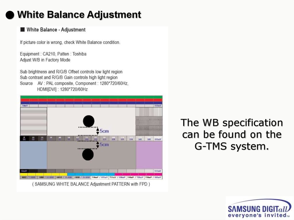
● White Balance AdjustmentThe WB specification
can be found on the
G-TMS system.
12.
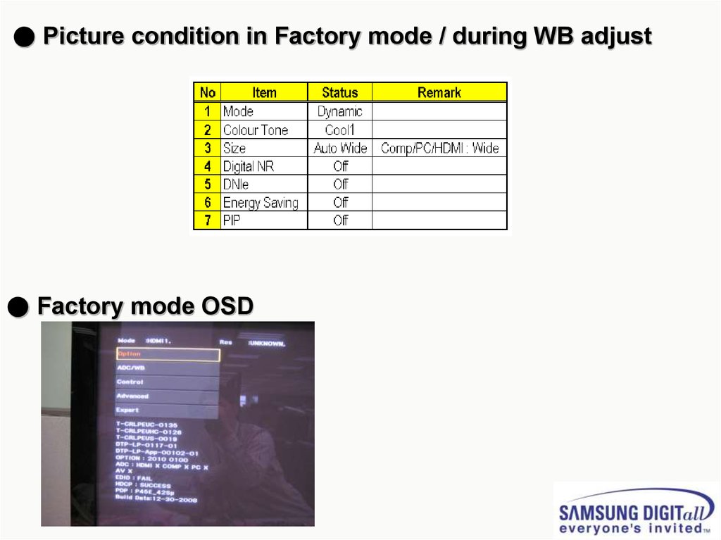
● Picture condition in Factory mode / during WB adjust● Factory mode OSD
13.
14.
15.
16.
17.
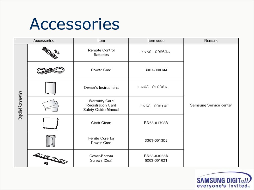
Accessories18.
2. Disassembly19.
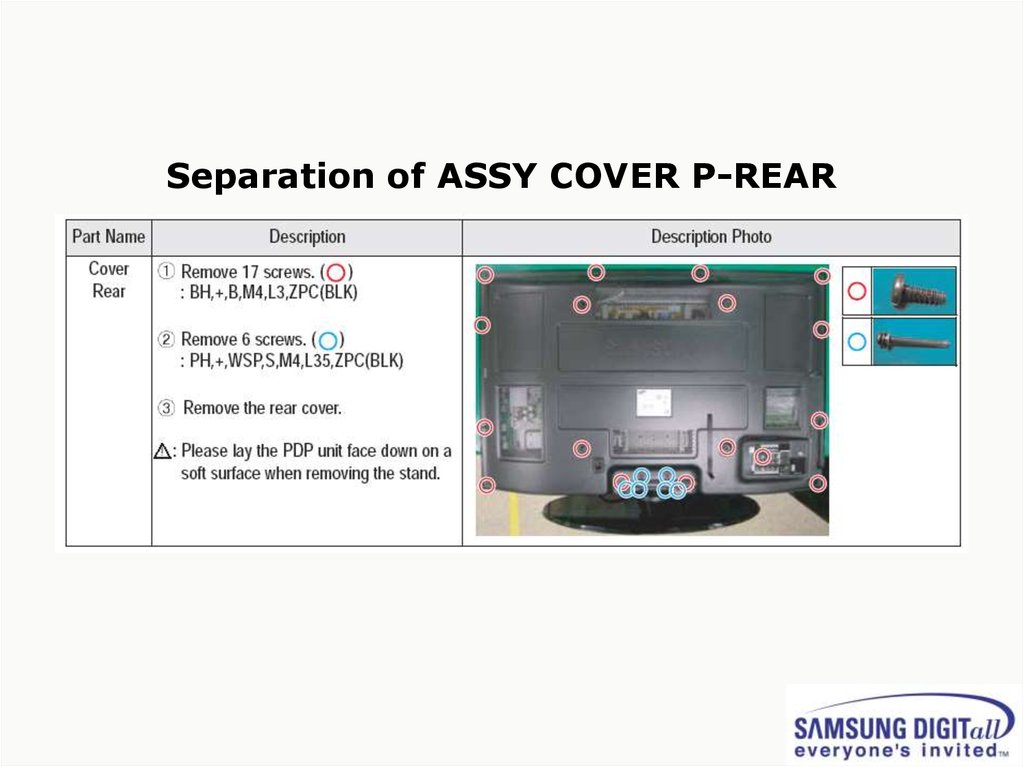
Separation of ASSY COVER P-REAR20.
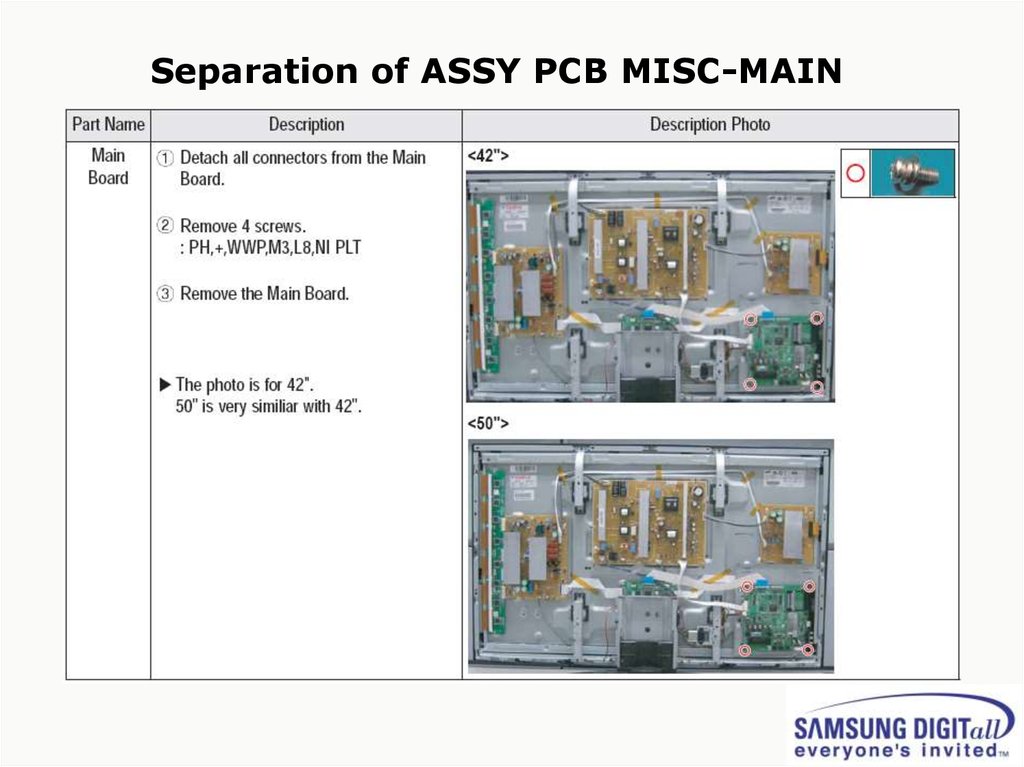
Separation of ASSY PCB MISC-MAIN21.
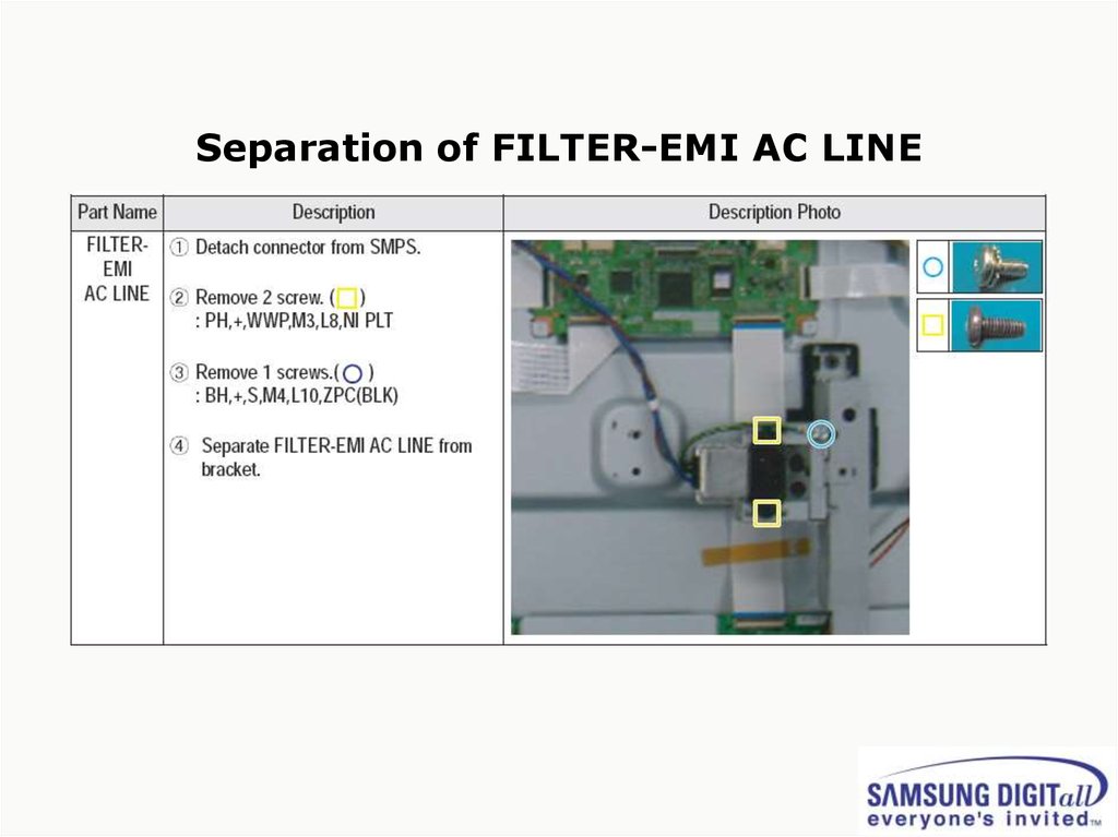
Separation of FILTER-EMI AC LINE22.
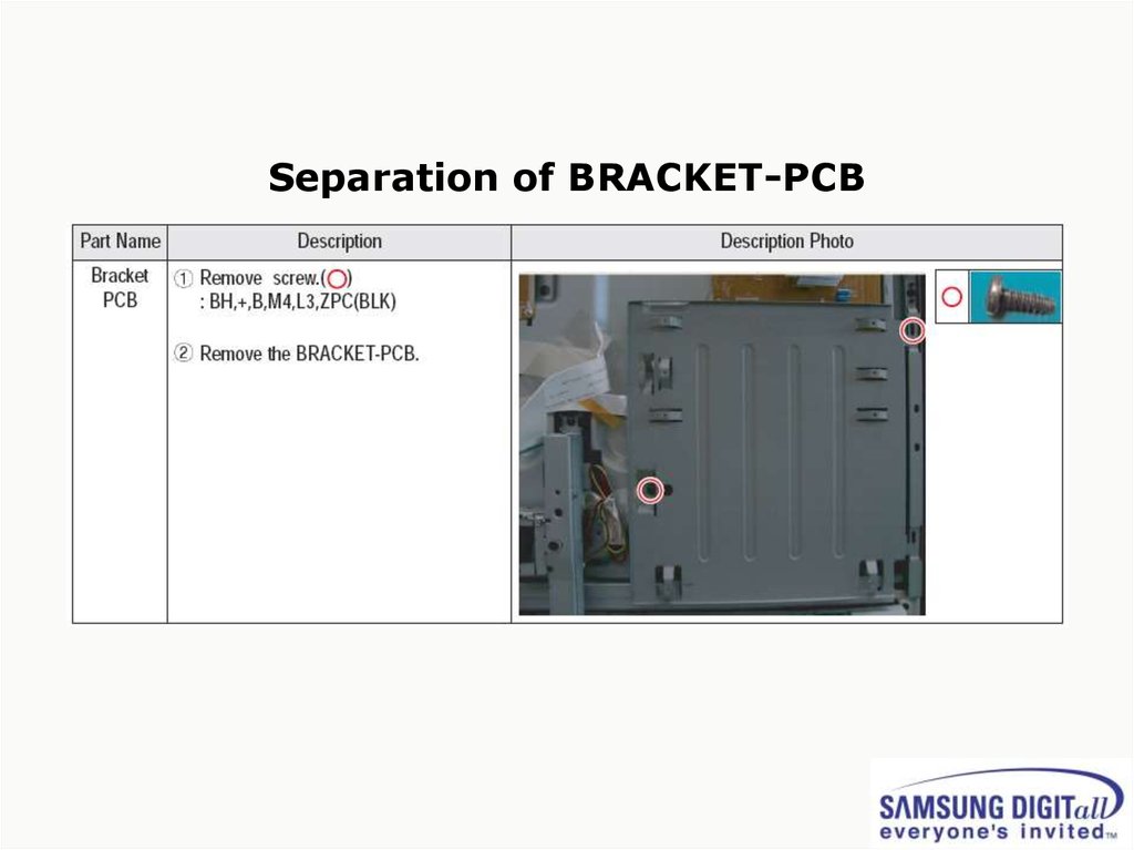
Separation of BRACKET-PCB23.
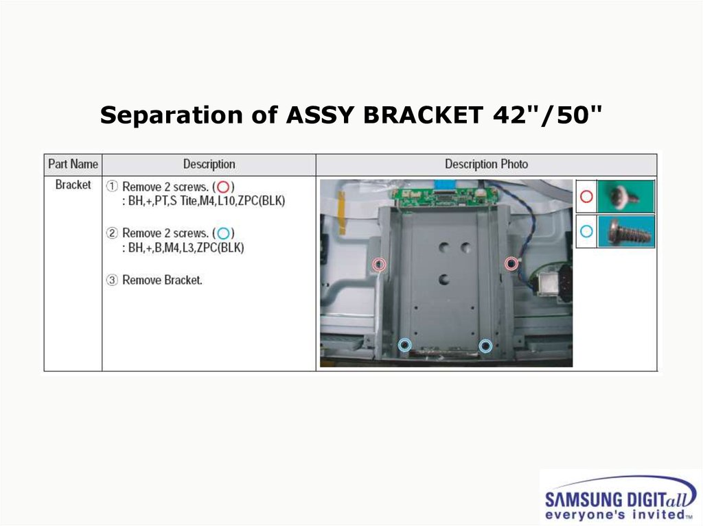
Separation of ASSY BRACKET 42"/50"24.
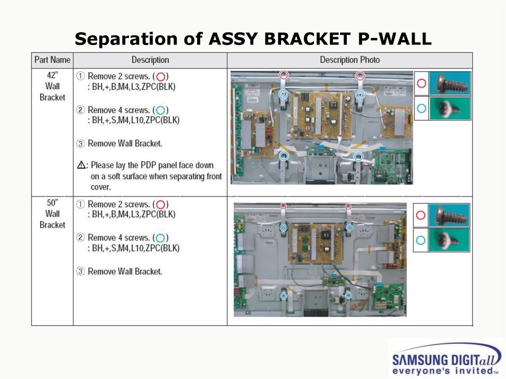
Separation of ASSY BRACKET P-WALL25.
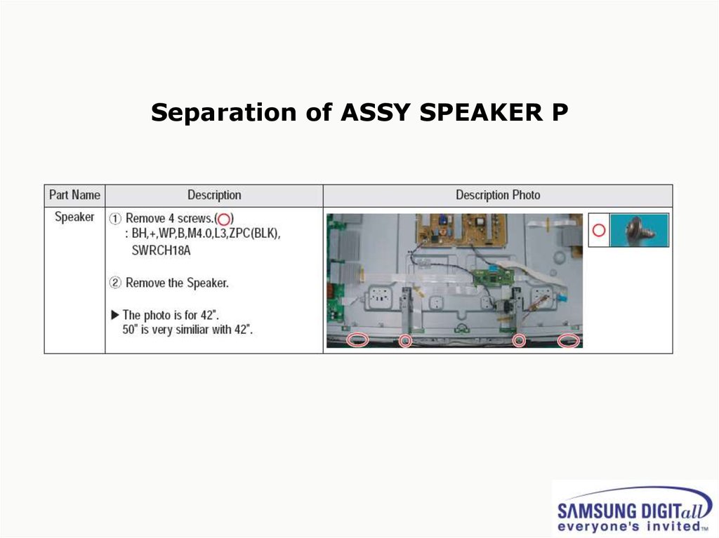
Separation of ASSY SPEAKER P26.
Separation of SMPS-PDP TV27.
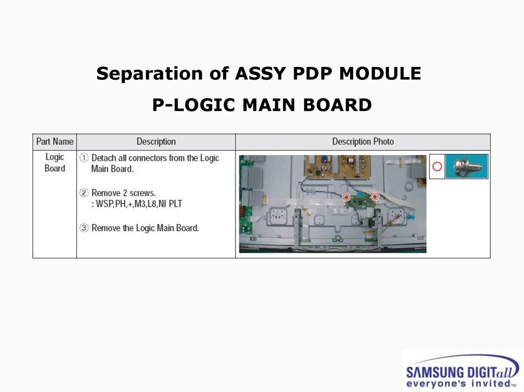
Separation of ASSY PDP MODULEP-LOGIC MAIN BOARD
28.
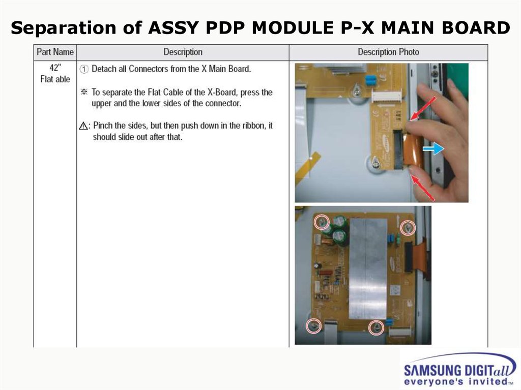
Separation of ASSY PDP MODULE P-X MAIN BOARD29.
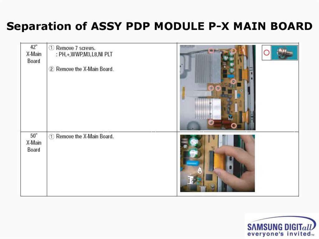
Separation of ASSY PDP MODULE P-X MAIN BOARD30.
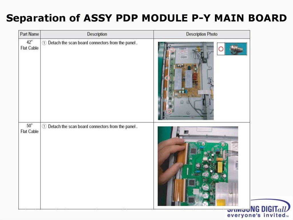
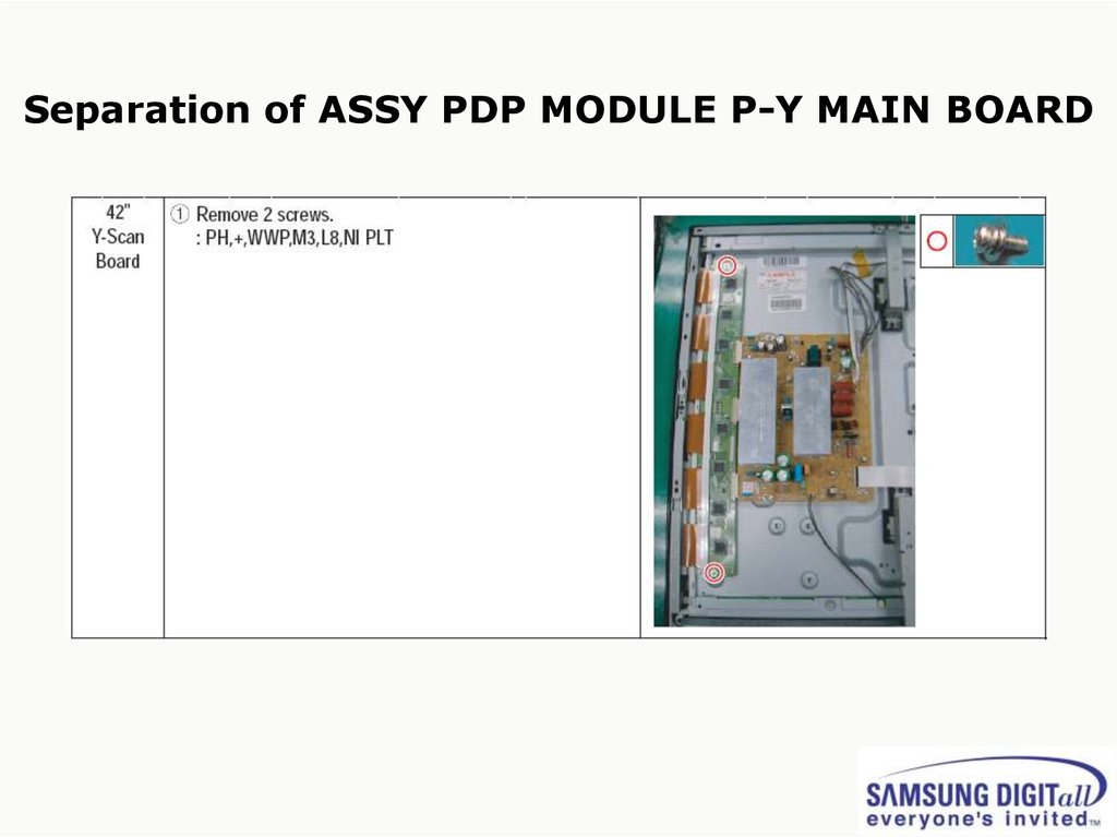
Separation of ASSY PDP MODULE P-Y MAIN BOARD31.
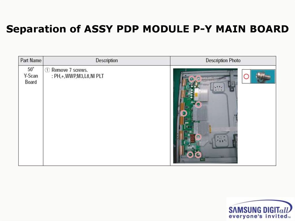
Separation of ASSY PDP MODULE P-Y MAIN BOARD32.
Separation of ASSY PDP MODULE P-Y MAIN BOARD33.
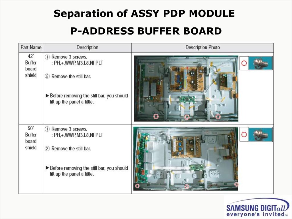
Separation of ASSY PDP MODULEP-ADDRESS BUFFER BOARD
34.
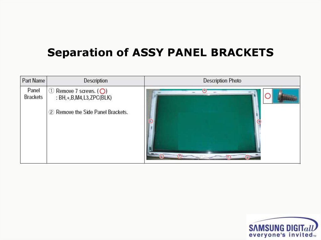
Separation of ASSY PANEL BRACKETS35.
3. Trouble shooting36.
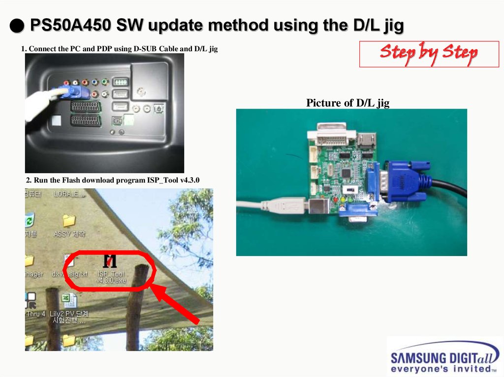
● PS50A450 SW update method using the D/L jig1. Connect the PC and PDP using D-SUB Cable and D/L jig
Step by Step
Picture of D/L jig
D-SUB Cable
2. Run the Flash download program ISP_Tool v4.3.0
37.
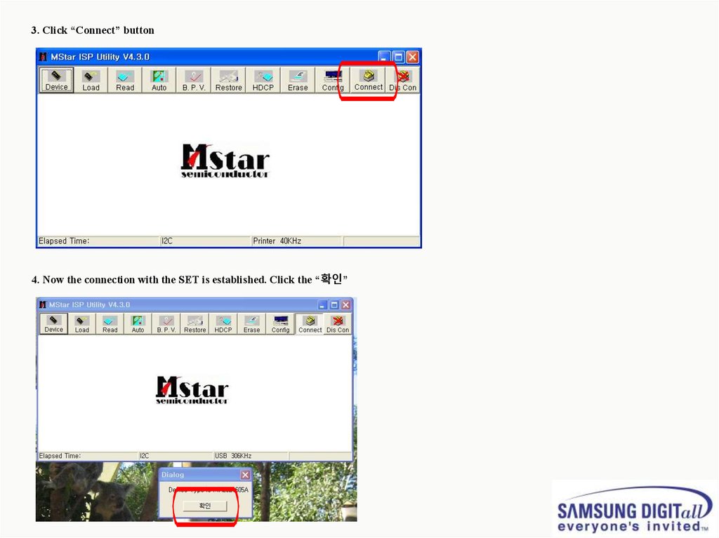
3. Click “Connect” button4. Now the connection with the SET is established. Click the “확인”
38.
5. Connect the Power cord and click “Read”①
②
6. Click the new “Read” button
39.
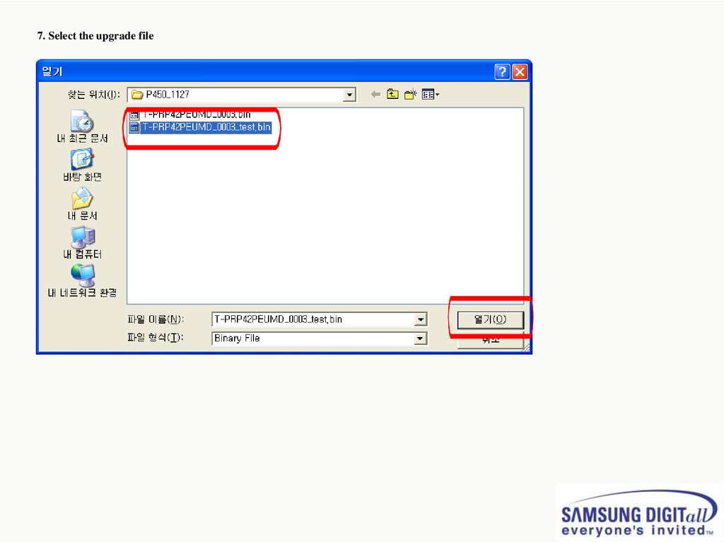
7. Select the upgrade file40.
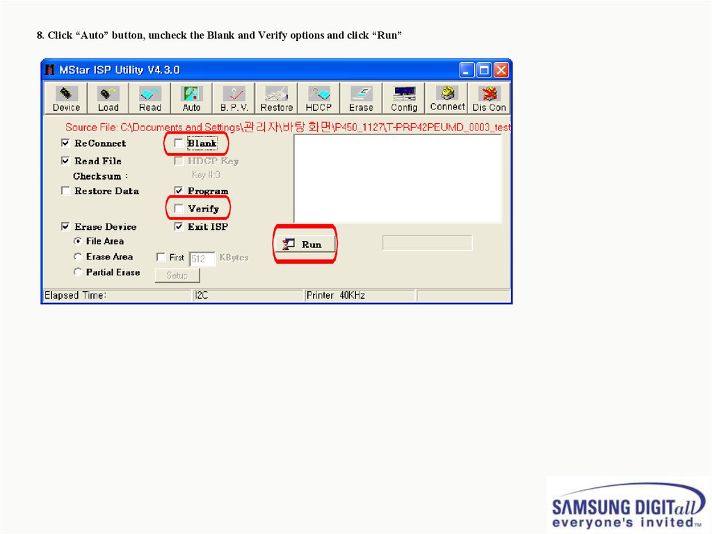
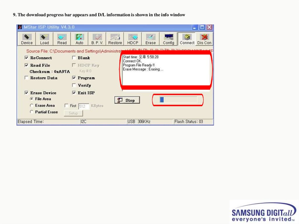
8. Click “Auto” button, uncheck the Blank and Verify options and click “Run”①
41.
9. The download progress bar appears and D/L information is shown in the info window42.
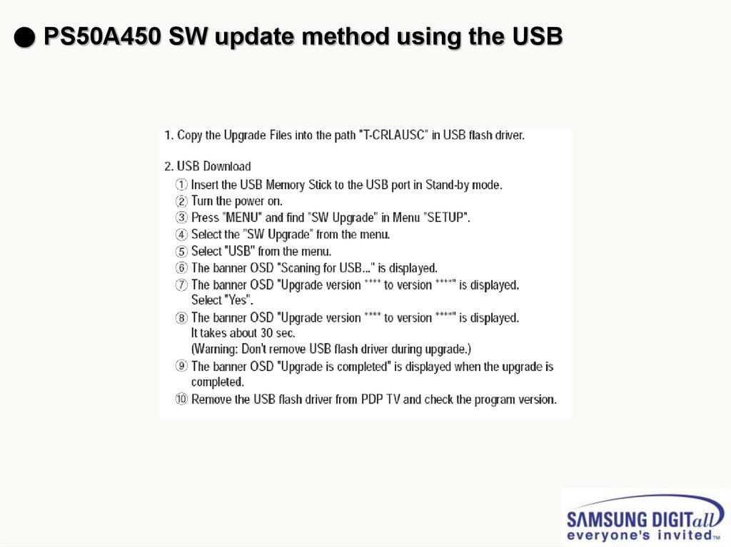
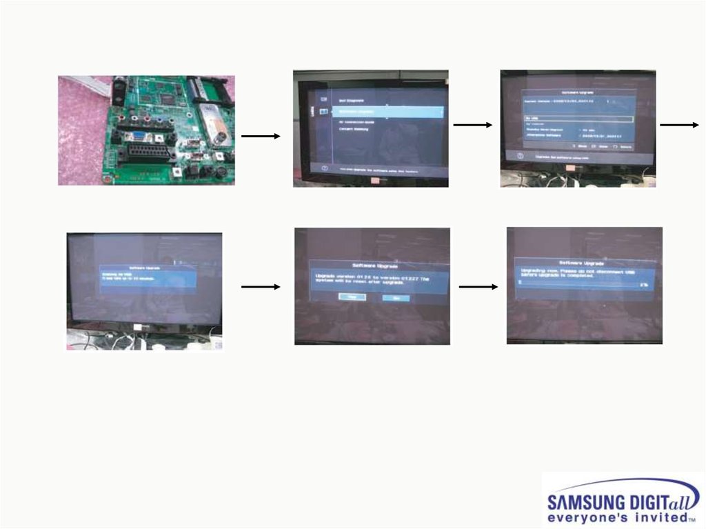
● PS50A450 SW update method using the USB43.
44.
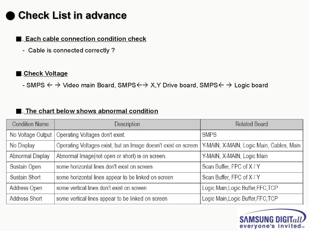
● Check List in advance■. Each cable connection condition check
- Cable is connected correctly ?
■.Check Voltage
- SMPS Video main Board, SMPS X,Y Drive board, SMPS Logic board
■. The chart below shows abnormal condition
45.
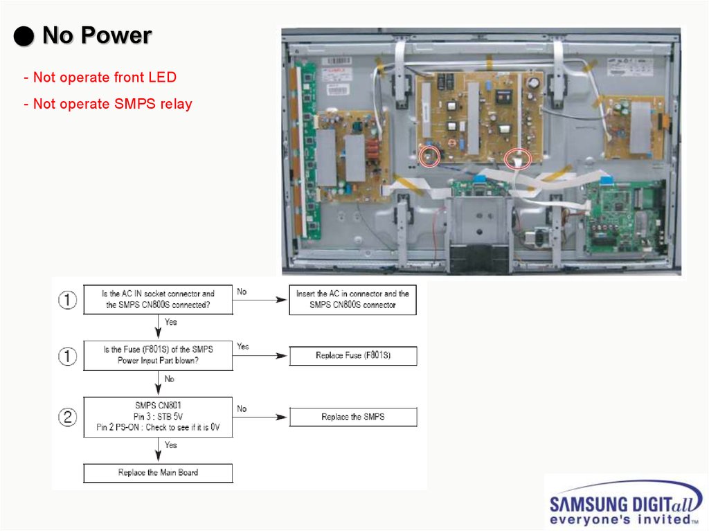
● No Power- Not operate front LED
- Not operate SMPS relay
46.
● SMPS relay on <-> off continually- Operate Protection circuit because
-of some Ass’y problem
47.
● No display but sound is normal- X or Y or Logic or Y Buffer board is abnormal
- SMPS output Voltage is abnormal
48.
● No sound but display is normal- Speaker wire is not connect
- Video main board sound part defect
- Speaker part defect
- Volume level is “0”(Non-sense)
49.
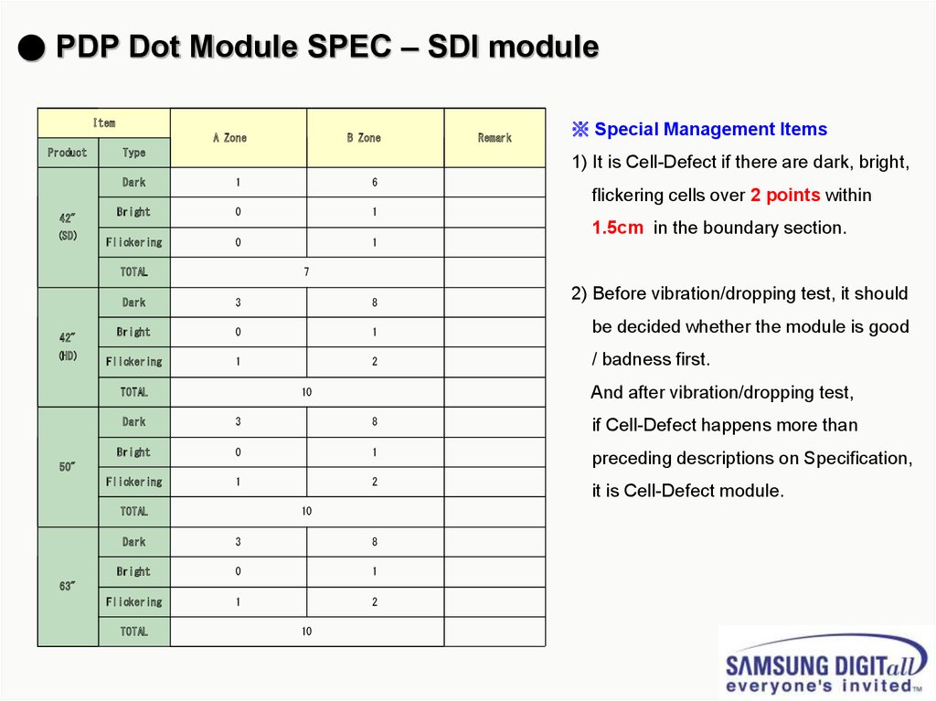
● PDP Dot Module SPEC – SDI moduleItem
A Zone
Product
B Zone
Type
Remark
※ Special Management Items
1) It is Cell-Defect if there are dark, bright,
Dark
1
6
Bright
0
1
Flickering
0
1
flickering cells over 2 points within
42"
(SD)
TOTAL
42"
(HD)
1.5cm in the boundary section.
7
Dark
3
8
2) Before vibration/dropping test, it should
Bright
0
1
be decided whether the module is good
Flickering
1
2
/ badness first.
TOTAL
And after vibration/dropping test,
10
Dark
3
8
if Cell-Defect happens more than
Bright
0
1
preceding descriptions on Specification,
Flickering
1
2
50"
TOTAL
10
Dark
3
8
Bright
0
1
Flickering
1
2
63"
TOTAL
10
it is Cell-Defect module.
50.
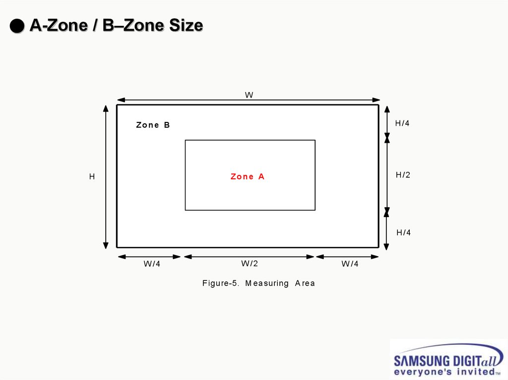
● A-Zone / B–Zone SizeW
H/4
Zone B
H
H/2
Zone A
H/4
W /4
W /2
F igure-5. M easuring A rea
W /4