


 electronics
Similar presentations:

")


Training Manual
1.
대외
보존기한
비
3년
31 Series
BX 2231/B X 2331/BX 2431
Training M anual
TS DR R &D G roup
MONITOR Lab
2.
C ontentsProduct Overview
OSD Adjustment
Circuit Description
Assembly and Disassembly
Troubleshooting
How to Execute Code
Etc.
3.
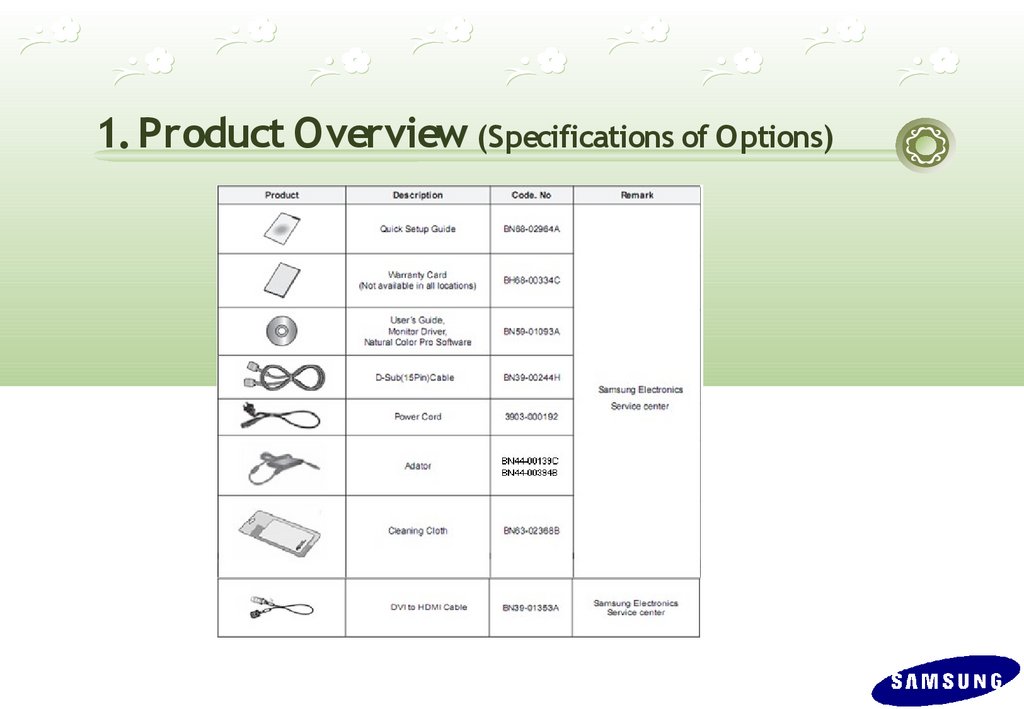
1. Product Overview (Specifications of Options)4.
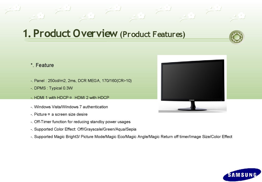
1. Product Overview (Product Features)*. Feature
-. Panel : 250cd/m2, 2ms, DCR MEGA, 170/160(CR>10)
-. DPMS : Typical 0.3W
-. HDMI 1 with HDCP HDMI 2 with HDCP
-. Windows Vista/Windows 7 authentication
-. Picture a screen size desire
-. Off-Timer function for reducing standby power usages
-. Supported Color Effect: Off/Grayscale/Green/Aqua/Sepia
-. Supported Magic Bright3/ Picture Mode/Magic Eco/Magic Angle/Magic Return off timer/Image Size/Color Effect
5.
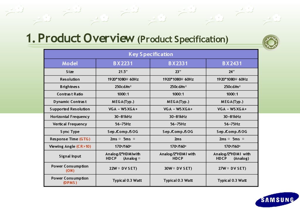
1. Product Overview (Product Specification)K ey S pecification
M odel
B X2231
B X2331
B X2431
S ize
21.5”
23”
24”
R es olution
1920*1080@ 60Hz
1920*1080@ 60Hz
1920*1080@ 60Hz
B rig htnes s
250cd/m 2
250cd/m2
250cd/m2
C ontras t R atio
1000:1
1000:1
1000:1
Dynamic C ontras t
M EG A(Typ.)
M EG A(Typ.)
M EG A(Typ.)
S upported R es olution
VG A ~ WS XGA+
VG A ~ WS XG A+
VG A ~ WS XG A+
Horizontal Frequency
30~81kHz
30~81kHz
30~81kHz
Vertical Frequency
56~75Hz
56~75Hz
56~75Hz
S ync Type
S ep./C omp./S OG
S ep./C omp./S OG
S ep./C omp./S OG
R es pons e Time (G TG )
2ms 5ms
2ms
2ms 5ms
Viewing Ang le (C R >10)
170o/160o
170o/160o
170o/160o
S ig nal Input
Analog /2*HDM Iwith
HDC P
(Analog
Analog /2*HDM I with
HDC P
Analog /2*HDM I with
HDC P
(Analog )
Power C ons umption
(ON)
22W DV S ET)
30W DV S ET)
27W DV S ET)
Typical 0.3 Watt
Typical 0.3 Watt
Power C ons umption
(DPM S )
Typical 0.3 Watt
6.
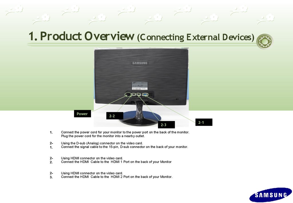
1. Product Overview (C onnecting External Devices)Power
2-2
2-3
1.
Connect the power cord for your monitor to the power port on the back of the monitor.
Plug the power cord for the monitor into a nearby outlet.
21.
Using the D-sub (Analog) connector on the video card.
Connect the signal cable to the 15-pin, D-sub connector on the back of your monitor.
22.
Using HDMI connector on the video card.
Connect the HDMI Cable to the HDMI 1 Port on the back of your Monitor
23.
Using HDMI connector on the video card.
Connect the HDMI Cable to the HDMI 2 Port on the back of your Monitor.
2-1
7.
1. Product Overview(Supported Display M odes)
BX 2231/BX 2331/BX 2431
8.
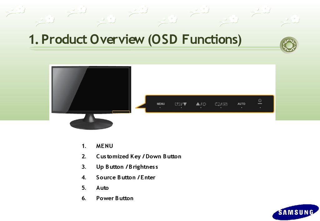
1. Product Overview (OSD Functions)1.
ME NU
2.
C us tomized K ey / Down B utton
3.
Up B utton / B rig htnes s
4.
S ource B utton / E nter
5.
Auto
6.
Power B utton
9.
1. Product Overview (OSD Functions)(1)
(2)
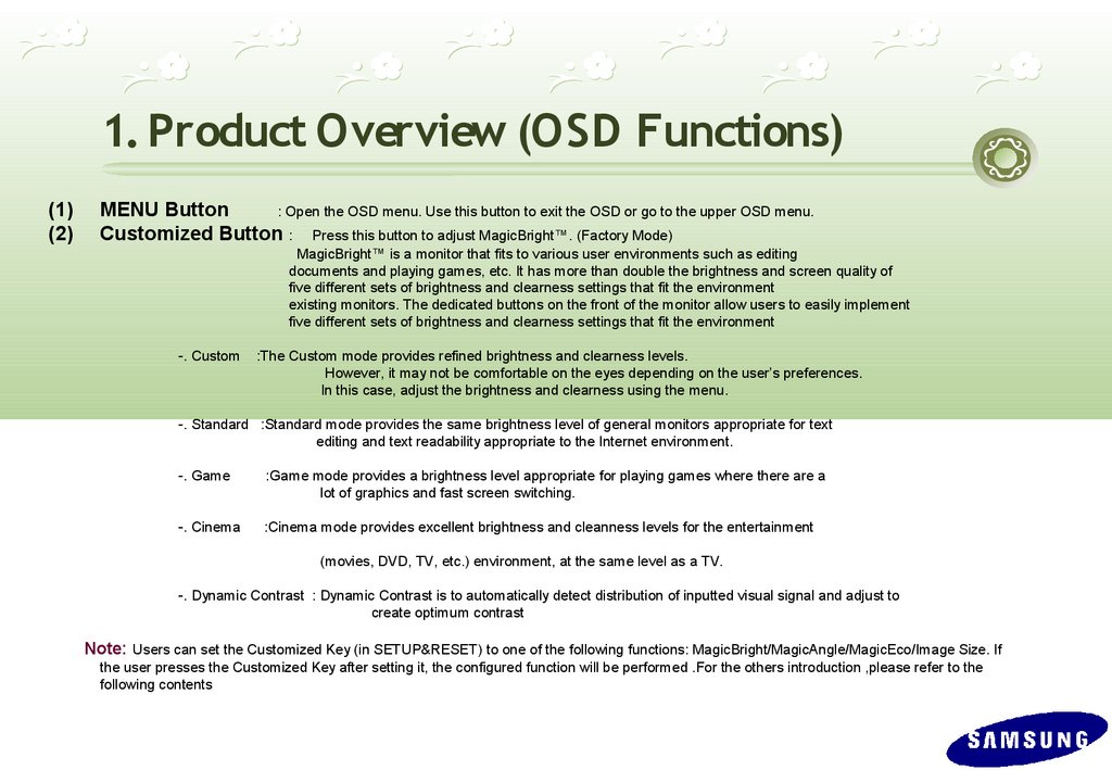
MENU Button
: Open the OSD menu. Use this button to exit the OSD or go to the upper OSD menu.
Customized Button : Press this button to adjust MagicBright™. (Factory Mode)
MagicBright™ is a monitor that fits to various user environments such as editing
documents and playing games, etc. It has more than double the brightness and screen quality of
five different sets of brightness and clearness settings that fit the environment
existing monitors. The dedicated buttons on the front of the monitor allow users to easily implement
five different sets of brightness and clearness settings that fit the environment
-. Custom
:The Custom mode provides refined brightness and clearness levels.
However, it may not be comfortable on the eyes depending on the user’s preferences.
In this case, adjust the brightness and clearness using the menu.
-. Standard :Standard mode provides the same brightness level of general monitors appropriate for text
editing and text readability appropriate to the Internet environment.
-. Game
:Game mode provides a brightness level appropriate for playing games where there are a
lot of graphics and fast screen switching.
-. Cinema
:Cinema mode provides excellent brightness and cleanness levels for the entertainment
(movies, DVD, TV, etc.) environment, at the same level as a TV.
-. Dynamic Contrast : Dynamic Contrast is to automatically detect distribution of inputted visual signal and adjust to
create optimum contrast
Note: Users can set the Customized Key (in SETUP&RESET) to one of the following functions: MagicBright/MagicAngle/MagicEco/Image Size. If
the user presses the Customized Key after setting it, the configured function will be performed .For the others introduction ,please refer to the
following contents
10.
1. Product Overview (OSD Functions)(2) Customized Button :
P res s this button to adjus t P icture M ode when s elect AV M ode by HD M I Input.
P icture M ode is a monitor that fits to various us er environments s uch as editing documents and playing
games , etc. It has more than double the brightness and s creen quality of exis ting monitors . The dedicated
buttons on the front of the monitor allow us ers to eas ily implement five different s ets of brightness and clearness
s ettings that fit the environment.
-. D ynamic
: S elect this mode to view a sharper image than in S tandard mode.
-. S tandard
: S elect this mode when the surroundings are bright. This also provides a sharp image.
-. M ovie
-. C ustom
: S elect this mode when the surroundings are dark. This will save power and reduce eye.
fatigue.
: S elect this mode when you want to adjust the image according to your preferences.
Note: Us ers can set the C us tomized Key(in S E TUP &R E S E T) to one of the following functions:M agicBright/M agicAngle/M agicE co/Imagie S ize
P C M ode P ictureM ode/M agicAngle/M agicE co/Imagie S ize AV M ode .
If the user presses the C us tom ized Key after setting it, the configured function will be performed .For the others introduction ,please
refer to the following contents .
11.
1. Product Overview (OSD Hidden K ey)1) Customized Key / Down Button
2) Up Button / Brightness
3) Source Button / Enter
: Us e this button to move around the O S D menu or change the value.
: Us e this button to adjus t the brightnes s of the s creen when Analog/D VI input.
Use this button to adjust the volume of the HD M I s ound when HD M I input.
: P res s this button to s elect a function and video source.
4) Auto Button
: If Button is press ed. Auto adjus tment function operates automatically.
(O nly in analog mode)
5) Power Button
: P ress this button to turn the monitor on or off.
12.
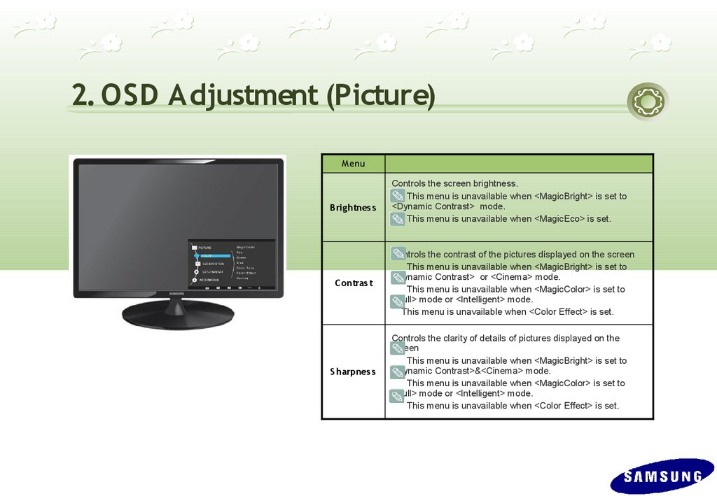
2. OSD Adjustment (Picture)M enu
B rig htnes s
C ontras t
S harpnes s
Controls the screen brightness.
This menu is unavailable when <MagicBright> is set to
<Dynamic Contrast> mode.
This menu is unavailable when <MagicEco> is set.
Controls the contrast of the pictures displayed on the screen
This menu is unavailable when <MagicBright> is set to
<Dynamic Contrast> or <Cinema> mode.
This menu is unavailable when <MagicColor> is set to
<Full> mode or <Intelligent> mode.
This menu is unavailable when <Color Effect> is set.
Controls the clarity of details of pictures displayed on the
screen
This menu is unavailable when <MagicBright> is set to
<Dynamic Contrast>&<Cinema> mode.
This menu is unavailable when <MagicColor> is set to
<Full> mode or <Intelligent> mode.
This menu is unavailable when <Color Effect> is set.
13.
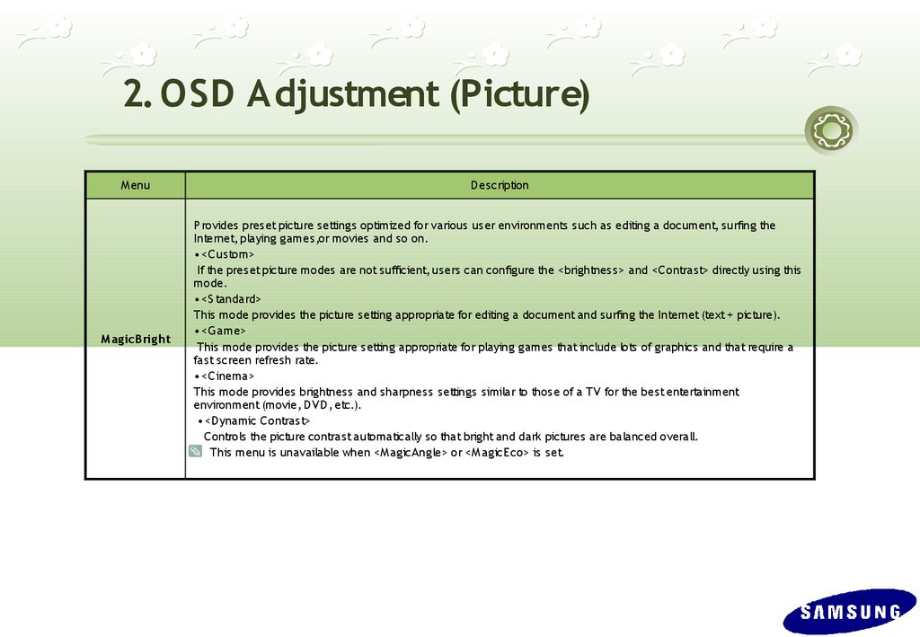
2. OSD Adjustment (Picture)M enu
D escription
M ag icB rig ht
P rovides pres et picture s ettings optimized for various us er environments s uch as editing a document, surfing the
Internet, playing games,or movies and so on.
• <C us tom>
If the pres et picture modes are not sufficient, users can configure the <brightnes s> and <C ontrast> directly using this
mode.
• <S tandard>
This mode provides the picture setting appropriate for editing a document and surfing the Internet (text + picture).
• <G ame>
This mode provides the picture s etting appropriate for playing games that include lots of graphics and that require a
fas t screen refresh rate.
• <C inema>
This mode provides brightness and s harpnes s settings similar to those of a TV for the best entertainment
environment (movie, D VD , etc.).
• <D ynamic C ontrast>
C ontrols the picture contrast automatically s o that bright and dark pictures are balanced overall.
This menu is unavailable when <M agicAngle> or <M agicE co> is s et.
14.
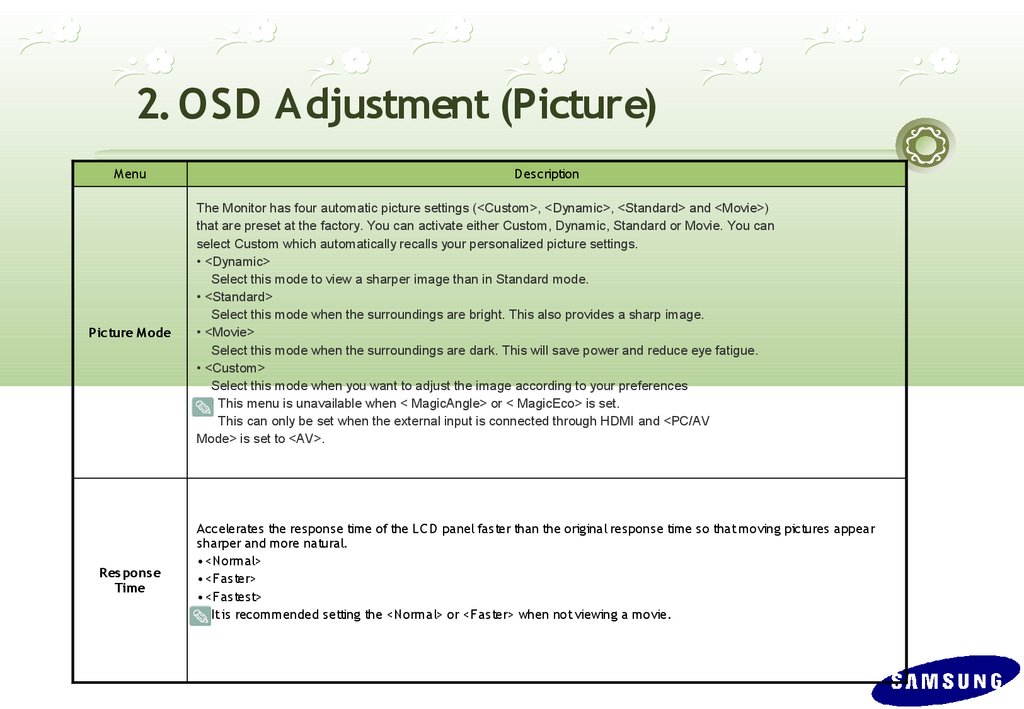
2. OSD Adjustment (Picture)M enu
Picture M ode
R es pons e
Time
D escription
The Monitor has four automatic picture settings (<Custom>, <Dynamic>, <Standard> and <Movie>)
that are preset at the factory. You can activate either Custom, Dynamic, Standard or Movie. You can
select Custom which automatically recalls your personalized picture settings.
• <Dynamic>
Select this mode to view a sharper image than in Standard mode.
• <Standard>
Select this mode when the surroundings are bright. This also provides a sharp image.
• <Movie>
Select this mode when the surroundings are dark. This will save power and reduce eye fatigue.
• <Custom>
Select this mode when you want to adjust the image according to your preferences
This menu is unavailable when < MagicAngle> or < MagicEco> is set.
This can only be set when the external input is connected through HDMI and <PC/AV
Mode> is set to <AV>.
Accelerates the response time of the LC D panel fas ter than the original response time so that moving pictures appear
sharper and more natural.
• <Normal>
• <Fas ter>
• <Fas test>
It is recommended setting the <Normal> or <Fas ter> when not viewing a movie.
15.
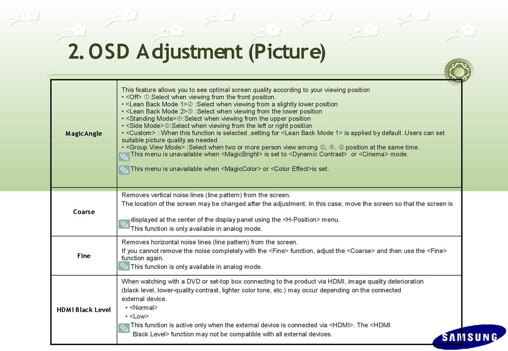
2. OSD Adjustment (Picture)M ag icAng le
This feature allows you to see optimal screen quality according to your viewing position
• <Off> ①:Select when viewing from the front position.
• <Lean Back Mode 1>② :Select when viewing from a slightly lower position
• <Lean Back Mode 2>③ :Select when viewing from the lower position
• <Standing Mode>④:Select when viewing from the upper position
• <Side Mode>⑤:Select when viewing from the left or right position
• <Custom> : When this function is selected ,setting for <Lean Back Mode 1> is applied by default .Users can set
suitable picture quality as needed
• <Group View Mode> :Select when two or more person view among ①, ④, ⑤ position at the same time.
This menu is unavailable when <MagicBright> is set to <Dynamic Contrast> or <Cinema> mode.
This menu is unavailable when <MagicColor> or <Color Effect>is set.
Removes vertical noise lines (line pattern) from the screen.
The location of the screen may be changed after the adjustment. In this case, move the screen so that the screen is
C oars e
displayed at the center of the display panel using the <H-Position> menu.
This function is only available in analog mode.
Fine
HDM I B lack Level
Removes horizontal noise lines (line pattern) from the screen.
If you cannot remove the noise completely with the <Fine> function, adjust the <Coarse> and then use the <Fine>
function again.
This function is only available in analog mode.
When watching with a DVD or set-top box connecting to the product via HDMI, image quality deterioration
(black level, lower-quality contrast, lighter color tone, etc.) may occur depending on the connected
external device.
• <Normal>
• <Low>
This function is active only when the external device is connected via <HDMI>. The <HDMI
Black Level> function may not be compatible with all external devices.
16.
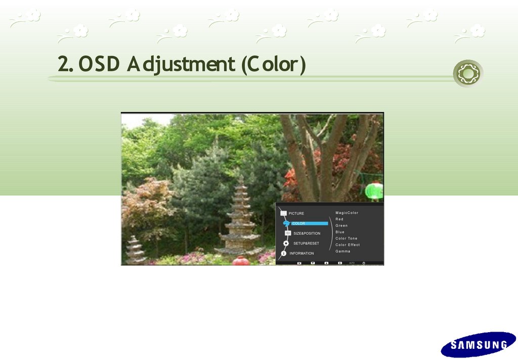
2. OSD Adjustment (C olor)17.
2. OSD Adjustment (C olor)M enu
D escription
M ag icC olor
Expresses natural colors more clearly without changing the picture quality using proprietary digital picture quality improvement
technology developed by Samsung Electronics.
• <Off> - Turns the MagicColor function off.
• <Demo> - You can compare the pictures processed by MagicColor with the original pictures.
• <Full> - Provides a clearer picture including areas corresponding to skin color.
• <Intelligent> - Improves the chroma of pictures except for areas corresponding to skin color.
This menu is unavailable when <MagicAngle> is set.
This menu is unavailable when <Color Effect> is set.
R ed
You can adjust the red color value of pictures according to your preference.
This menu is unavailable when <MagicColor> is set to <Full> mode or <Intelligent> mode.
This menu is unavailable when <Color Effect> is set.
G reen
You can adjust the green color value of pictures according to your preference.
This menu is unavailable when <MagicColor> is set to <Full> mode or <Intelligent> mode.
This menu is unavailable when <Color Effect> is set.
B lue
You can adjust the blue color value of pictures according to your preference.
This menu is unavailable when <MagicColor> is set to <Full> mode or <Intelligent> mode.
This menu is unavailable when <Color Effect> is set.
C olor Tone
You can set the color temperature according to your preference.
• <Cool> - Sets the color temperature of the screen to a cooler color.
• <Normal> - Sets the color temperature of the screen to the standard color temperature.
• <Warm> - Sets the color temperature of the screen to a warmer color.
• <Custom> - Select this menu to set the color temperature manually. If you do not like the preset color temperatures, you can
manually adjust the colors of <Color Effect>.
This menu is unavailable when <MagicColor> is set to <Full> mode or <Intelligent> mode.
This menu is unavailable when <MagicAngle> is set.
This menu is unavailable when <Color Effect> is set.
18.
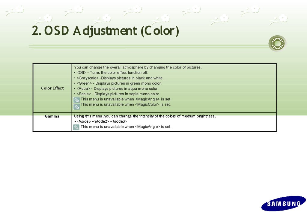
2. OSD Adjustment (C olor)C olor Effect
G amma
You can change the overall atmosphere by changing the color of pictures.
• <Off> - Turns the color effect function off.
• <Grayscale> -Displays pictures in black and white.
• <Green> - Displays pictures in green mono color.
• <Aqua> - Displays pictures in aqua mono color.
• <Sepia> - Displays pictures in sepia mono color.
This menu is unavailable when <MagicAngle> is set.
This menu is unavailable when <MagicColor> is set.
Us ing this menu, you can change the intens ity of the colors of medium brightness .
• <M odel>-<M ode2>-<M ode3>
This menu is unavailable when <MagicAngle> is set.
19.
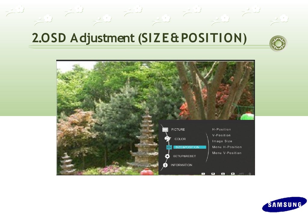
2.OSD Adjustment (SI Z E& POSI TI ON)20.
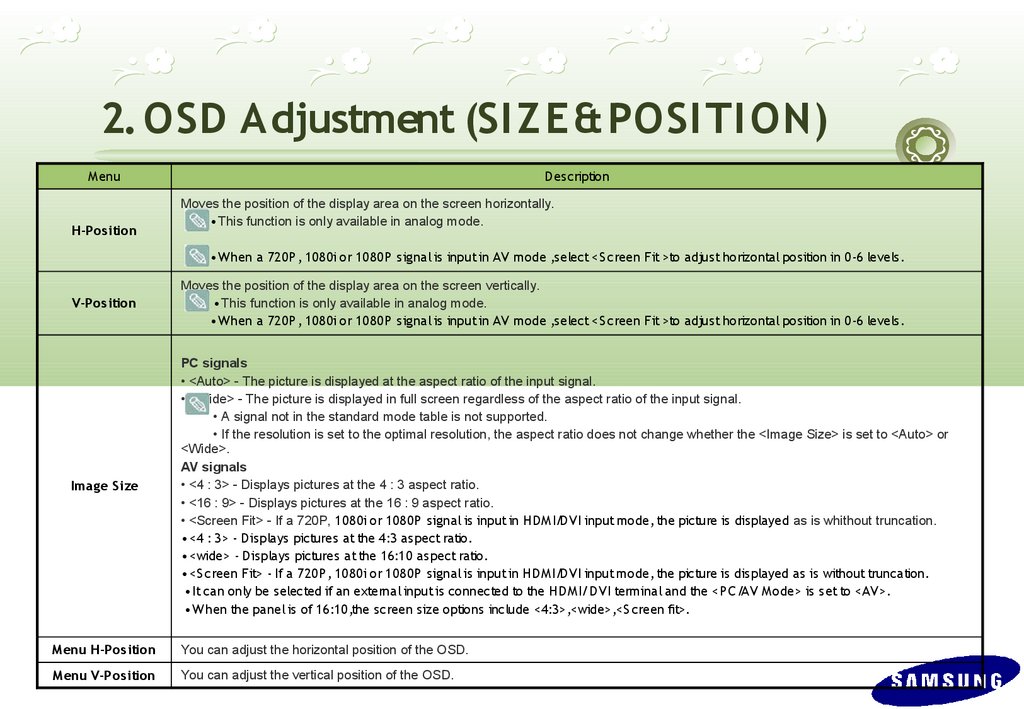
2. OSD Adjustment (SI Z E& POSI TI ON)M enu
H-Pos ition
D es cription
Moves the position of the display area on the screen horizontally.
• This function is only available in analog mode.
• W hen a 720P , 1080i or 1080P s ignal is input in AV mode ,s elect <S creen Fit >to adjus t horizontal pos ition in 0-6 levels .
V-Pos ition
Moves the position of the display area on the screen vertically.
• This function is only available in analog mode.
• W hen a 720P , 1080i or 1080P s ignal is input in AV mode ,s elect <S creen Fit >to adjus t horizontal pos ition in 0-6 levels .
Imag e S ize
PC signals
• <Auto> - The picture is displayed at the aspect ratio of the input signal.
• <Wide> - The picture is displayed in full screen regardless of the aspect ratio of the input signal.
• A signal not in the standard mode table is not supported.
• If the resolution is set to the optimal resolution, the aspect ratio does not change whether the <Image Size> is set to <Auto> or
<Wide>.
AV signals
• <4 : 3> - Displays pictures at the 4 : 3 aspect ratio.
• <16 : 9> - Displays pictures at the 16 : 9 aspect ratio.
• <Screen Fit> - If a 720P, 1080i or 1080P s ignal is input in HD M I/D VI input mode, the picture is displayed as is whithout truncation.
• <4 : 3> - D isplays pictures at the 4:3 aspect ratio.
• <wide> - D isplays pictures at the 16:10 aspect ratio.
• <S creen Fit> - If a 720P , 1080i or 1080P s ignal is input in HD M I/D VI input mode, the picture is displayed as is without truncation.
• It can only be selected if an external input is connected to the HD M I/D VI terminal and the <P C /AV M ode> is s et to <AV>.
• W hen the panel is of 16:10,the s creen size options include <4:3>,<wide>,<S creen fit>.
M enu H-Pos ition
You can adjust the horizontal position of the OSD.
M enu V-Pos ition
You can adjust the vertical position of the OSD.
21.
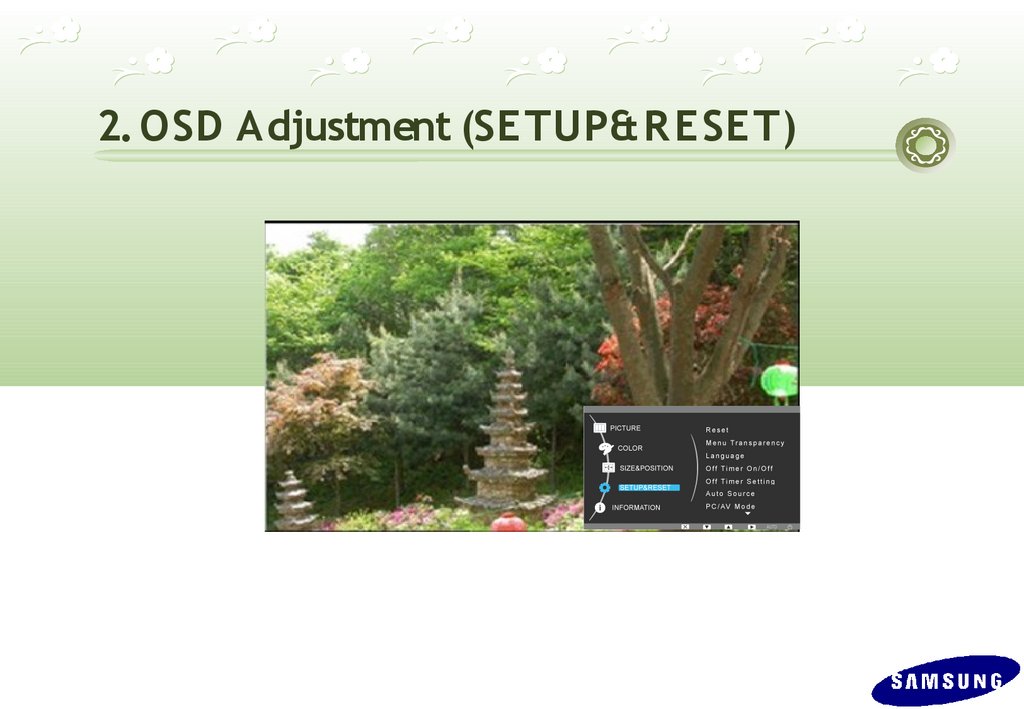
2. OSD Adjustment (SETUP& R E SE T)22.
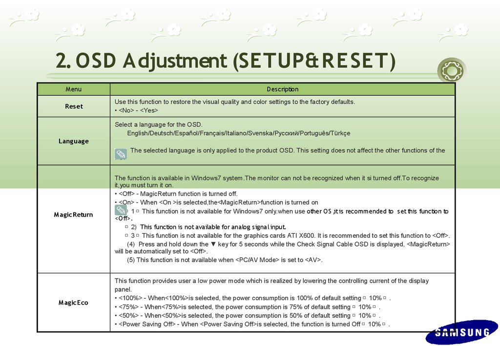
2. OSD Adjustment (SETUP& R ESET)M enu
R es et
D escription
Use this function to restore the visual quality and color settings to the factory defaults.
• <No> - <Yes>
Select a language for the OSD.
English/Deutsch/Español/Français/Italiano/Svenska/Русский/Português/Türkçe
Lang uag e
PC.
M ag icR eturn
M ag icE co
The selected language is only applied to the product OSD. This setting does not affect the other functions of the
The function is available in Windows7 system.The monitor can not be recognized when it si turned off.To recognize
it,you must turn it on.
• <Off> - MagicReturn function is turned off.
• <On> - When <On >is selected,the<MagicReturn>function is turned on
1 This function is not available for Windows7 only.when use other O S ,it is recommended to set this function to
<O ff>.
2) This function is not available for analog signal input.
3 This function is not available for the graphics cards ATI X600. It is recommended to set this function to <Off>.
(4) Press and hold down the ▼ key for 5 seconds while the Check Signal Cable OSD is displayed, <MagicReturn>
will be automatically set to <Off>.
(5) This function is not available when <PC/AV Mode> is set to <AV>.
This function provides user a low power mode which is realized by lowering the controlling current of the display
panel.
• <100%> - When<100%>is selected, the power consumption is 100% of default setting 10% .
• <75%> - When<75%>is selected, the power consumption is 75% of default setting 10% .
• <50%> - When<50%>is selected, the power consumption is 50% of default setting 10% .
• <Power Saving Off> - When <Power Saving Off>is selected, the function is turned Off 10% .
23.
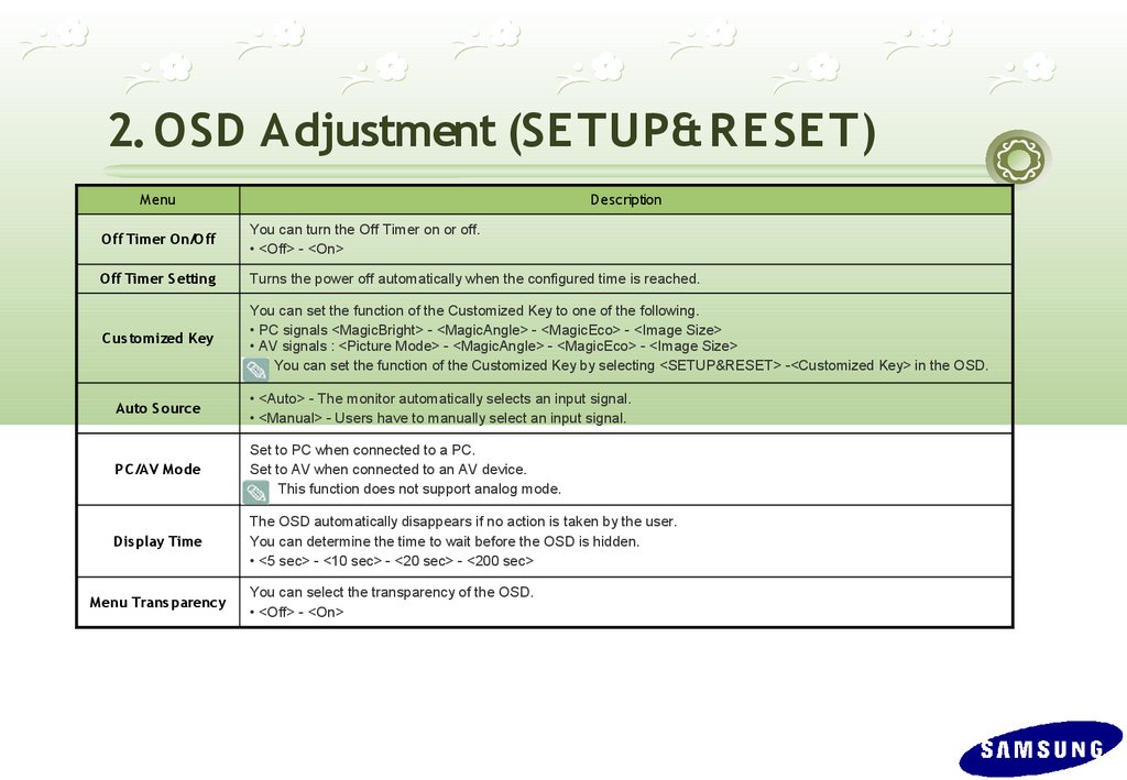
2. OSD Adjustment (SETUP& R ESET)M enu
D escription
Off Timer On/Off
You can turn the Off Timer on or off.
• <Off> - <On>
Off Timer S etting
Turns the power off automatically when the configured time is reached.
C us tomized K ey
You can set the function of the Customized Key to one of the following.
• PC signals <MagicBright> - <MagicAngle> - <MagicEco> - <Image Size>
• AV signals : <Picture Mode> - <MagicAngle> - <MagicEco> - <Image Size>
You can set the function of the Customized Key by selecting <SETUP&RESET> -<Customized Key> in the OSD.
Auto S ource
• <Auto> - The monitor automatically selects an input signal.
• <Manual> - Users have to manually select an input signal.
PC /AV M ode
Set to PC when connected to a PC.
Set to AV when connected to an AV device.
This function does not support analog mode.
Dis play Time
The OSD automatically disappears if no action is taken by the user.
You can determine the time to wait before the OSD is hidden.
• <5 sec> - <10 sec> - <20 sec> - <200 sec>
M enu Trans parency
You can select the transparency of the OSD.
• <Off> - <On>
24.
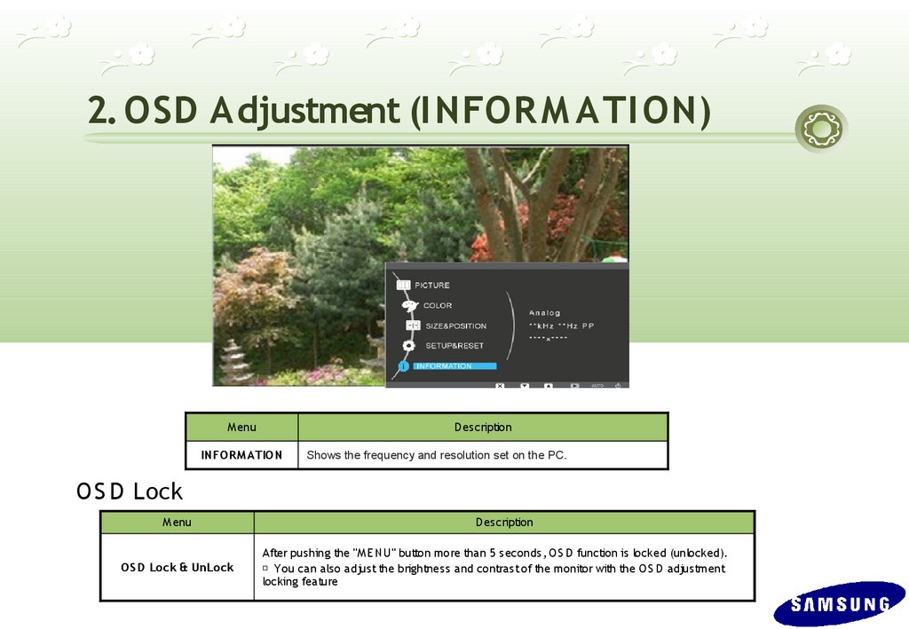
2. OSD Adjustment (I NFOR M ATI ON)M enu
D es cription
INFOR M ATION
Shows the frequency and resolution set on the PC.
O S D Lock
M enu
OS D Lock & UnLock
D es cription
After pus hing the "M E NU" button more than 5 seconds, O S D function is locked (unlocked).
※ You can als o adjust the brightness and contras t of the monitor with the O S D adjustment
locking feature
25.
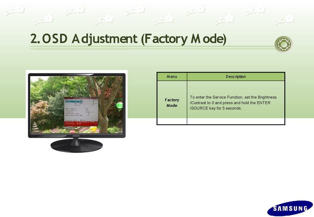
2. OSD Adjustment (Factory M ode)M enu
Factory
M ode
D escription
To enter the Service Function, set the Brightness
/Contrast to 0 and press and hold the ENTER
/SOURCE key for 5 seconds.
26.
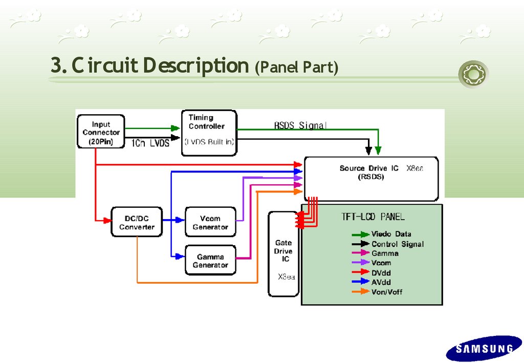
3. C ircuit Description (Product Structure)1. Panel Part
S ee
P roduct S pecifications.
2. Mai n Boar d Par t
Receives external PC analog signals, and then outputs the video signals to
the panel using a Scaler and also outputs the same signals as external input.
3. LED DRI VER
LED
DRIVER
4. Function B utton
Transfers the input signals where the Function button is used to the main
board and displays the LE D .
27.
3. C ircuit Description (New Part)*. Scaler(MSTR)
SE979LMRD-LF
Use a type of scaler with an embedded MCU core.
-. Detailed Specifications
On-Chip Microcontroller
On-Chip OSD Controller
LVDS/RSDS Transmitters
128-QFP Package / 3.3V/1.8V suppliers
28.
3. C ircuit Description (Panel Part)29.
3. C ircuit Description (Panel Part)* PROTECTION*
LAMP(Inverter) PROTECION
=> The protection is activated if there is no feedback because the lamp connector
is disconnected or the lamp is cracked.
=> The over voltage protection starts as a lamp protection if the output voltage of
the inverter transformer is high.
Power Protection
=> All panel protection (OVP/OCP) operates in Auto Recovery mode. When the
panel is stopped temporarily due to a protection issue, it powers the panel on again
to resume the operation after the problem is cleared.
However, as an exception, in the case of a thermal protection issue, the panel can
only operate normally if the power is turned off and is fully discharged and turned on
again. This is controlled by a function designed in the power IC.
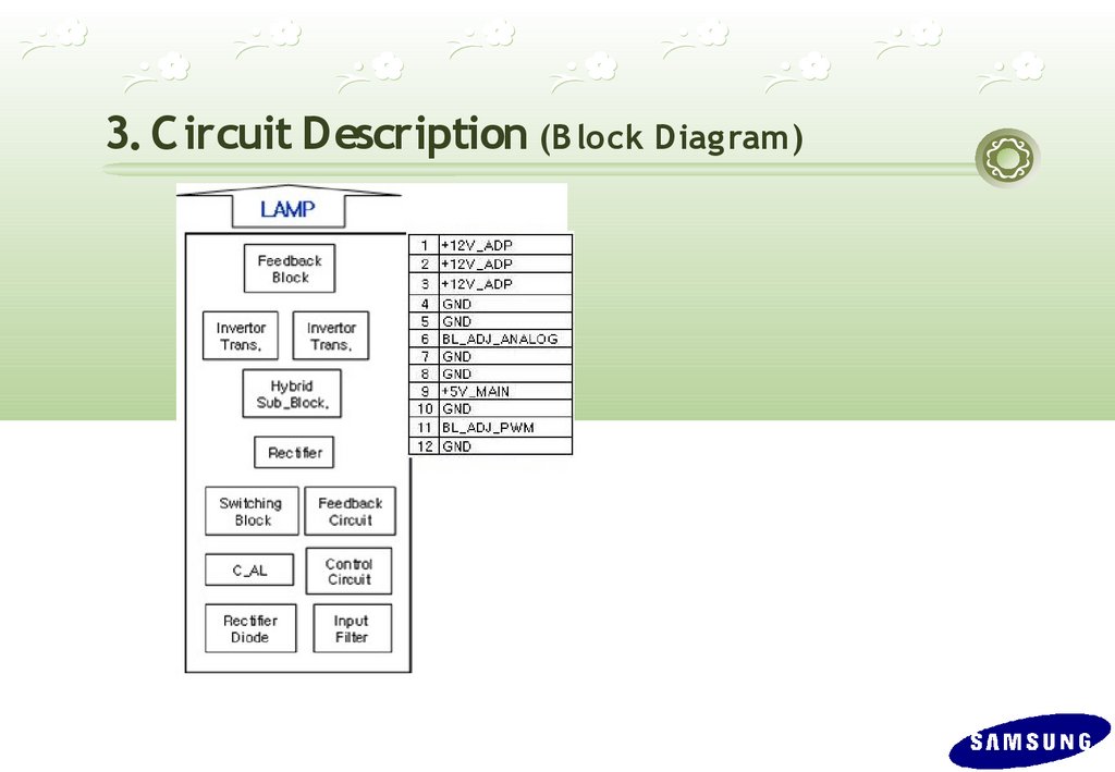
30.
3. C ircuit Description (B lock Diag ram)31.
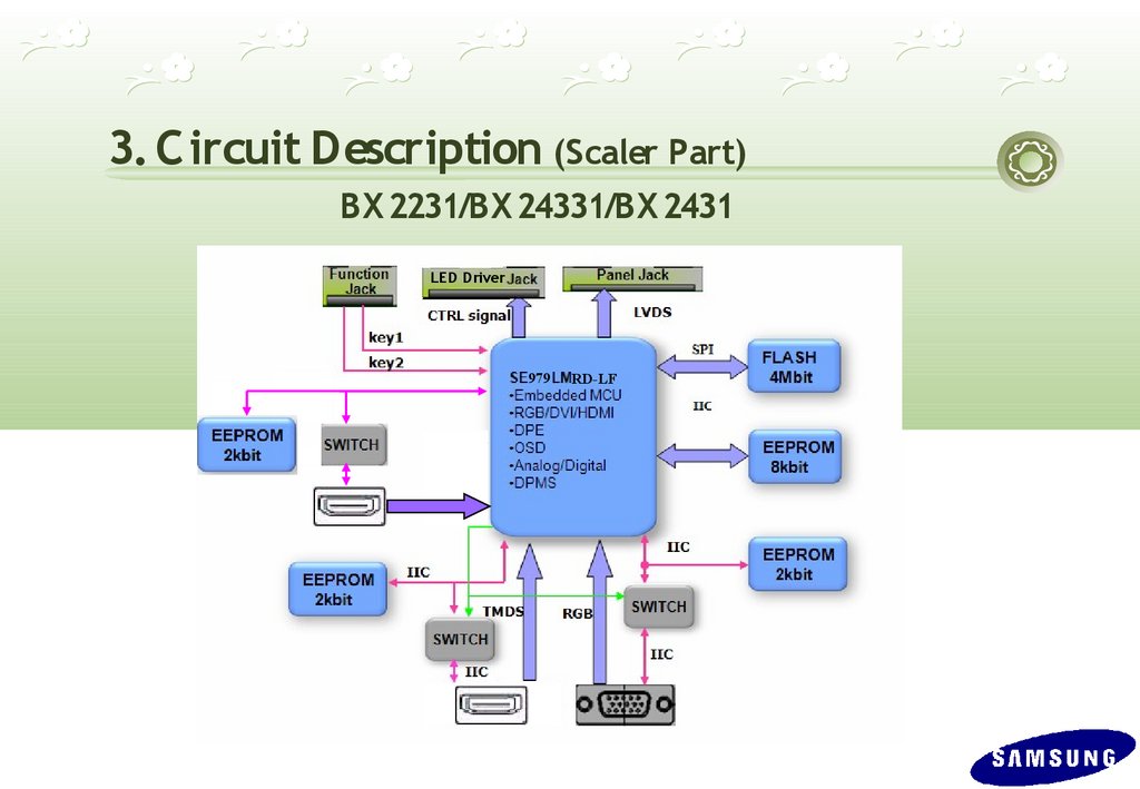
3. C ircuit Description (Scaler Part)BX 2231/BX 24331/BX 2431
LED Driver
979
RD-LF
32.
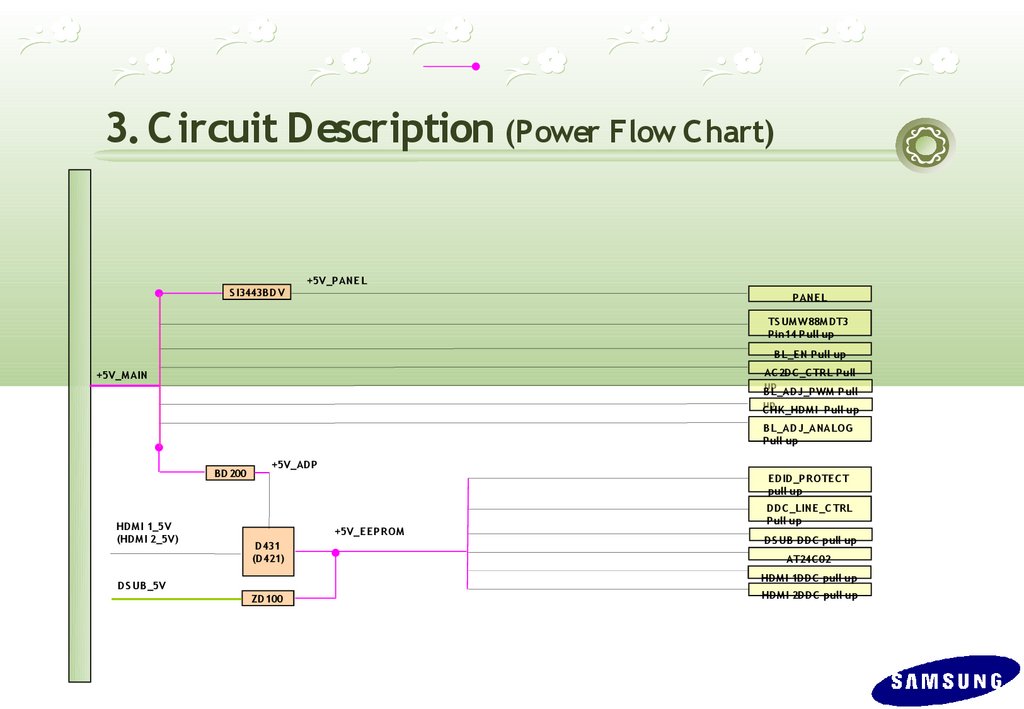
3. C ircuit Description (Power Flow C hart)S I3443B DV
+5V_PANE L
PANE L
TS UM W 88M DT3
Pin14 Pull up
B L_E N Pull up
AC 2DC _C TR L Pull
up
B L_ADJ_PWM Pull
up
C HK _HDM I Pull up
+5V_M AIN
B L_ADJ_ANALOG
Pull up
B D200
HDM I 1_5V
(HDM I 2_5V)
+5V_ADP
E DID_PR OTE C T
pull up
+5V_E E PR OM
D431
(D421)
DDC _LINE _C TR L
Pull up
DS UB DDC pull up
AT24C 02
HDM I 1DDC pull up
DS UB _5V
ZD100
HDM I 2DDC pull up
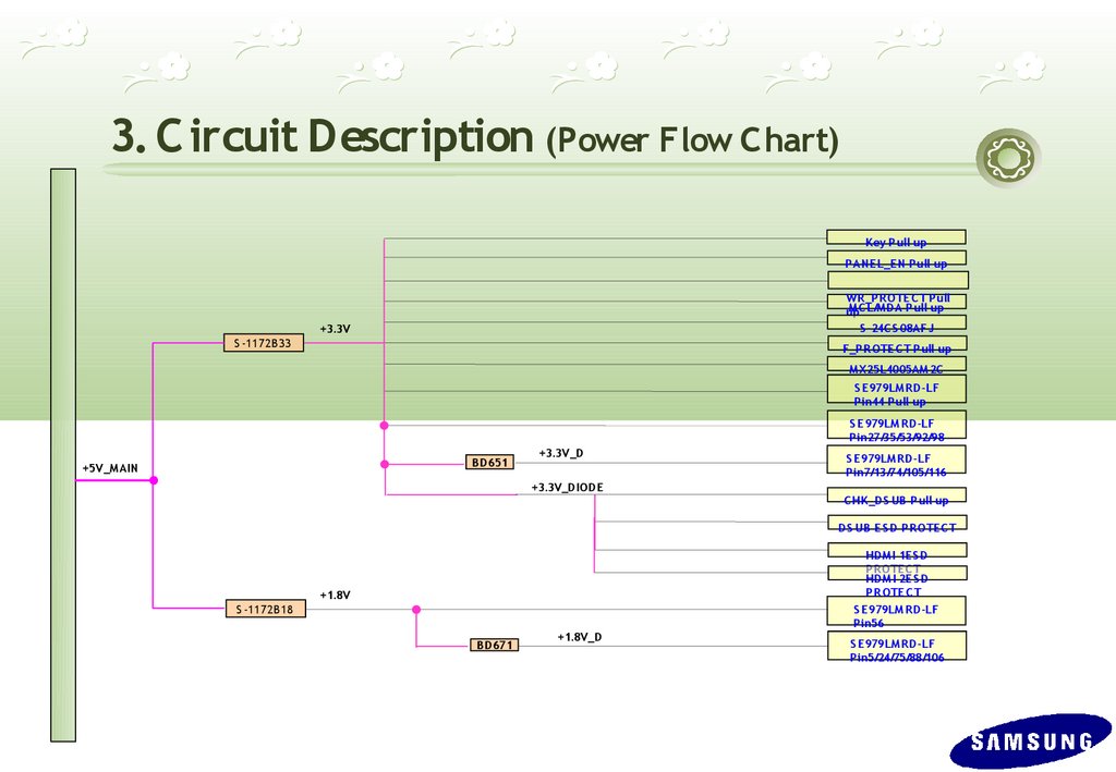
33.
3. C ircuit Description (Power Flow C hart)Key P ull up
P ANE L_EN Pull up
WR _PR OTE C T Pull
M C L/M DA Pull up
up
S -24C S 08AFJ
+3.3V
S -1172B 33
F_PR OTE C T Pull up
M X25L4005AM 2C
S E 979LM R D-LF
Pin44 P ull up
S E 979LM R D-LF
Pin27/35/53/92/98
B D651
+5V_M AIN
+3.3V_D
S E 979LM R D-LF
Pin7/13/74/105/116
+3.3V_DIODE
C HK _DS UB Pull up
DS UB E S D PR OTE C T
HDM I 1E S D
PR OTE C T
HDM I 2E S D
PR OTE C T
S E 979LM R D-LF
Pin56
+1.8V
S -1172B 18
B D671
+1.8V_D
S E 979LM R D-LF
Pin5/24/75/88/106
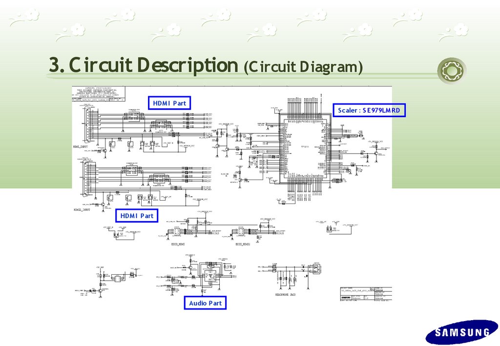
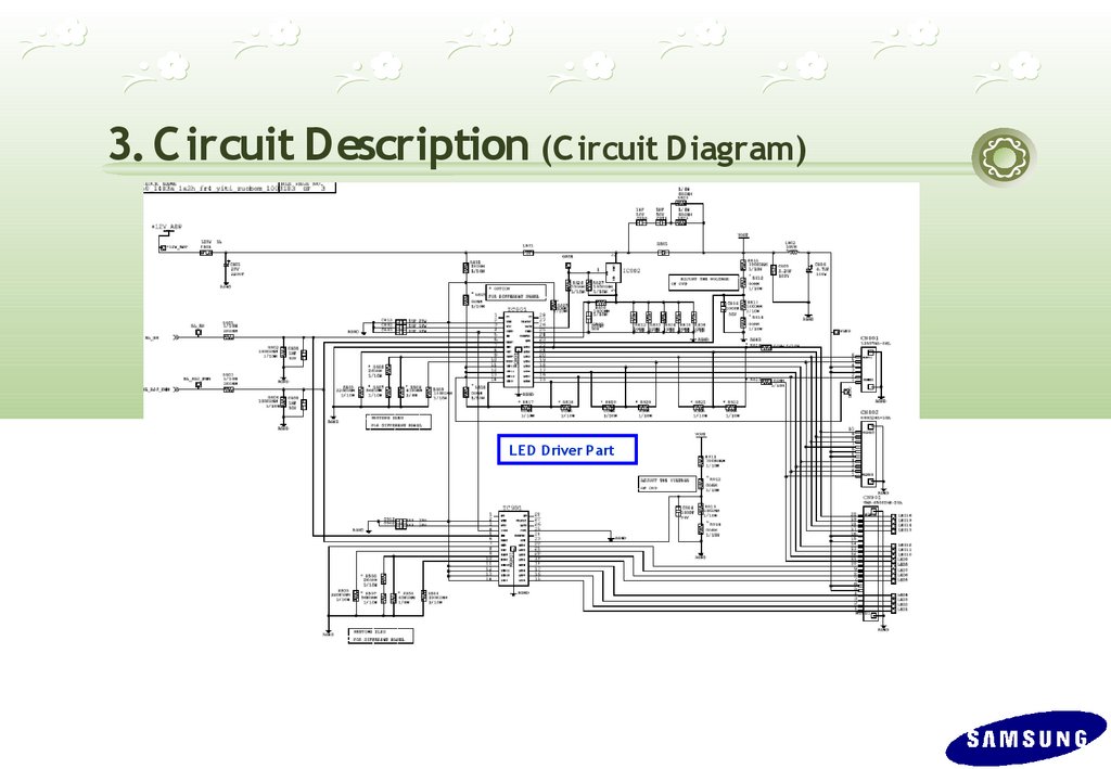
34.
3. C ircuit Description (C ircuit Diagram)HDM I Part
S caler : S E979LM R D
HDM I Part
Audio Part
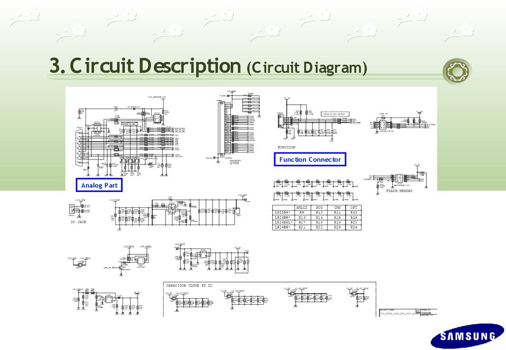
35.
3. C ircuit Description (C ircuit Diagram)Function C onnector
Analog Part
36.
3. C ircuit Description (C ircuit Diagram)LED Driver Part
37.
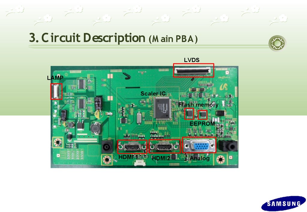
3. C ircuit Description (M ain PBA)LVDS
LAMP
Scaler IC
Flash memory
EEPROM
HDMI 1
HDMI2
Analog
38.
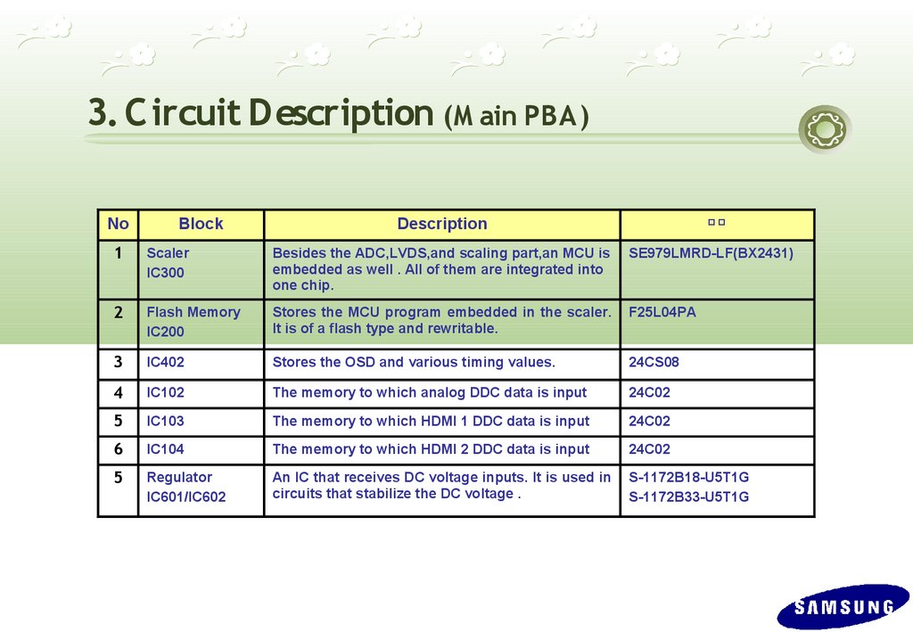
3. C ircuit Description (M ain PBA)No
Block
비고
Description
1
Scaler
IC300
Besides the ADC,LVDS,and scaling part,an MCU is
embedded as well . All of them are integrated into
one chip.
SE979LMRD-LF(BX2431)
2
Flash Memory
IC200
Stores the MCU program embedded in the scaler.
It is of a flash type and rewritable.
F25L04PA
3
IC402
Stores the OSD and various timing values.
24CS08
4
IC102
The memory to which analog DDC data is input
24C02
5
IC103
The memory to which HDMI 1 DDC data is input
24C02
6
IC104
The memory to which HDMI 2 DDC data is input
24C02
5
Regulator
IC601/IC602
An IC that receives DC voltage inputs. It is used in
circuits that stabilize the DC voltage .
S-1172B18-U5T1G
S-1172B33-U5T1G
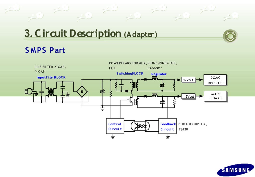
39.
3. C ircuit Description (Adapter)S MPS Part
LINE FILTE R ,X -C AP ,
Y-C AP
P O W E RTR ANS FO R M E R , D IO D E ,IND UC TO R ,
C apacitor
FE T
S witchingB LOC K
InputFilterB LOC K
R eg ulator
12V out
12V out
Cont r ol
Ci r cui t
Feedback P HO TO C O UP LE R ,
Ci r cui t
TL430
D C/A C
INV ERTER
M A IN
B OA RD
40.
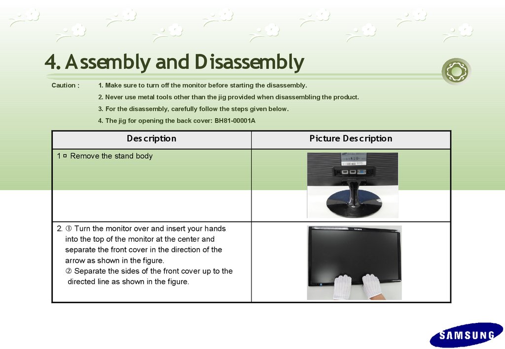
4. Assembly and DisassemblyCaution :
1. Make sure to turn off the monitor before starting the disassembly.
2. Never use metal tools other than the jig provided when disassembling the product.
3. For the disassembly, carefully follow the steps given below.
4. The jig for opening the back cover: BH81-00001A
Des cription
1 、 Remove the stand body
2. ① Turn the monitor over and insert your hands
into the top of the monitor at the center and
separate the front cover in the direction of the
arrow as shown in the figure.
② Separate the sides of the front cover up to the
directed line as shown in the figure.
Picture Des cription
41.
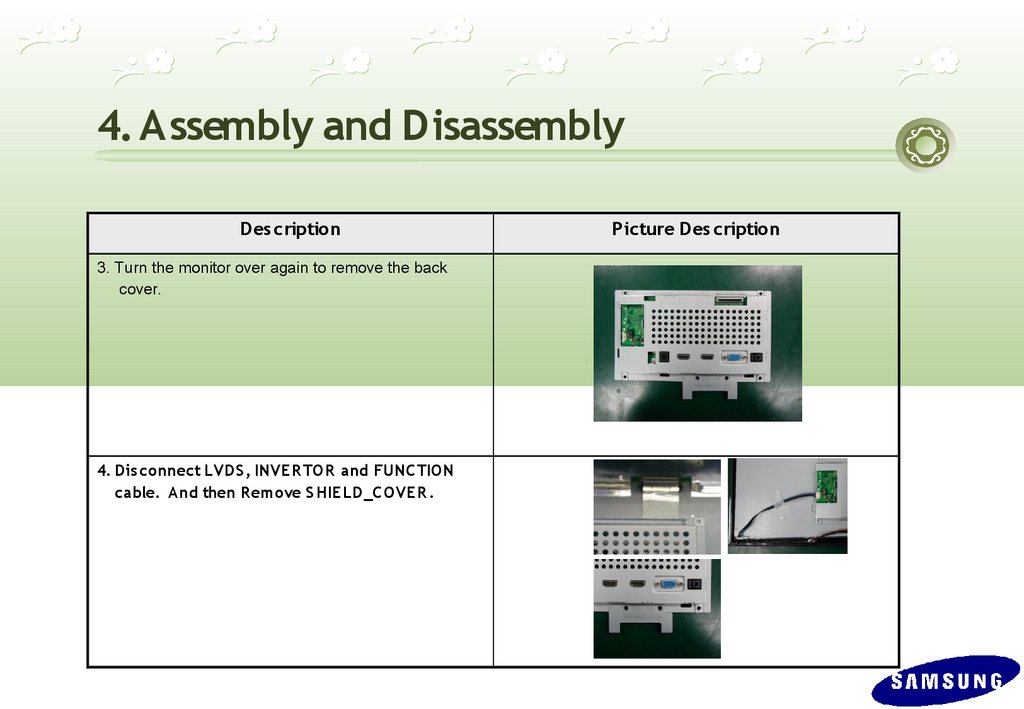
4. Assembly and DisassemblyDes cription
3. Turn the monitor over again to remove the back
cover.
4. Dis connect LVDS , INVER TOR and FUNC TION
cable. And then R emove S HIE LD_C OVER .
Picture Des cription
42.
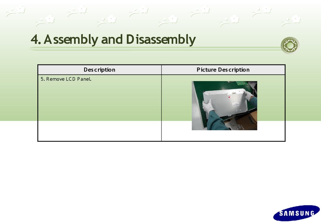
4. Assembly and DisassemblyDes cription
5. R emove LC D P anel.
Picture Des cription
43.
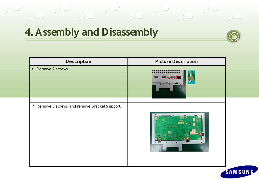
4. Assembly and DisassemblyDes cription
6. R emove 2 screws.
7. R emove 3 screws and remove B racket S upport.
Picture Des cription
44.
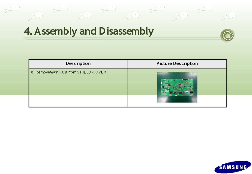
4. Assembly and DisassemblyDes cription
8. R emoveM ain P C B from S HIE LD -C O VE R .
Picture Des cription
45.
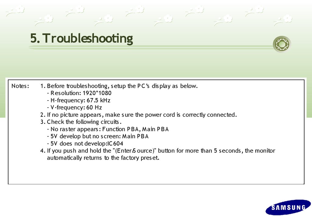
5. TroubleshootingNotes:
1. Before troubleshooting, s etup the P C ’s dis play as below.
- R es olution: 1920*1080
- H-frequency: 67.5 kHz
- V-frequency: 60 Hz
2. If no picture appears, make sure the power cord is correctly connected.
3. C heck the following circuits .
- No raster appears : Function P BA, M ain P B A
- 5V develop but no screen: M ain P B A
- 5V does not develop:IC 604
4. If you pus h and hold the "(E nter/S ource)" button for more than 5 seconds , the monitor
automatically returns to the factory pres et.
46.
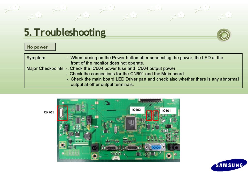
5. TroubleshootingNo power
Symptom
: -. When turning on the Power button after connecting the power, the LED at the
front of the monitor does not operate.
Major Checkpoints: -. Check the IC604 power fuse and IC604 output power.
-. Check the connections for the CN601 and the Main board.
-. Check the main board LED Driver part and check also whether there is any abnormal
output at other output terminals.
C N901
IC 602
IC 601
47.
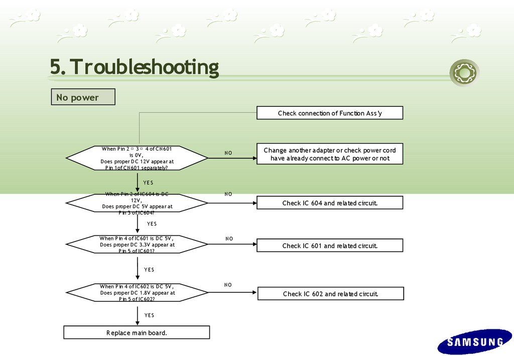
5. TroubleshootingNo power
C heck connection of Function Ass’y
W hen P in 2 3 4 of C N601
is 0V,
D oes proper D C 12V appear at
P in 1of C N601 s eparately?
NO
C hange another adapter or check power cord
have already connect to AC power or not
YE S
W hen P in 2 of IC 604 is D C
12V,
D oes proper D C 5V appear at
P in 3 of IC 604?
NO
C heck IC 604 and related circuit.
YE S
W hen P in 4 of IC 601 is DC 5V,
D oes proper DC 3.3V appear at
P in 5 of IC 601?
NO
C heck IC 601 and related circuit.
YE S
W hen P in 4 of IC 602 is D C 5V,
D oes proper D C 1.8V appear at
P in 5 of IC 602?
YES
R eplace main board.
NO
C heck IC 602 and related circuit.
48.
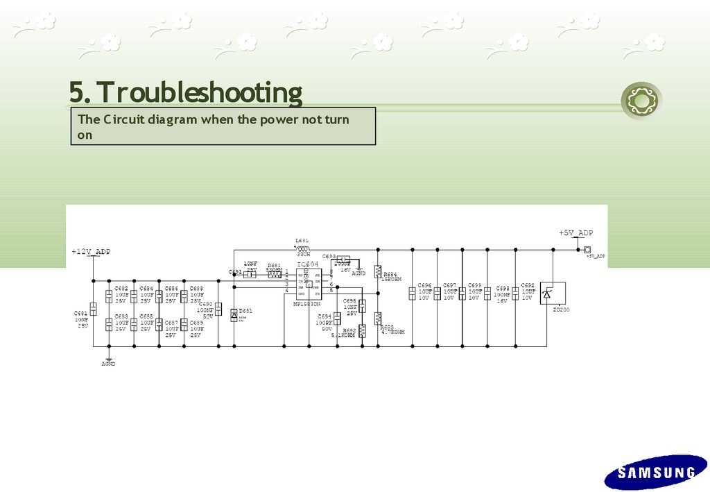
5. TroubleshootingThe C ircuit diag ram when the power not turn
on
49.
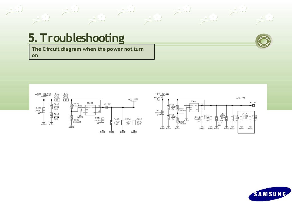
5. TroubleshootingThe C ircuit diag ram when the power not turn
on
50.
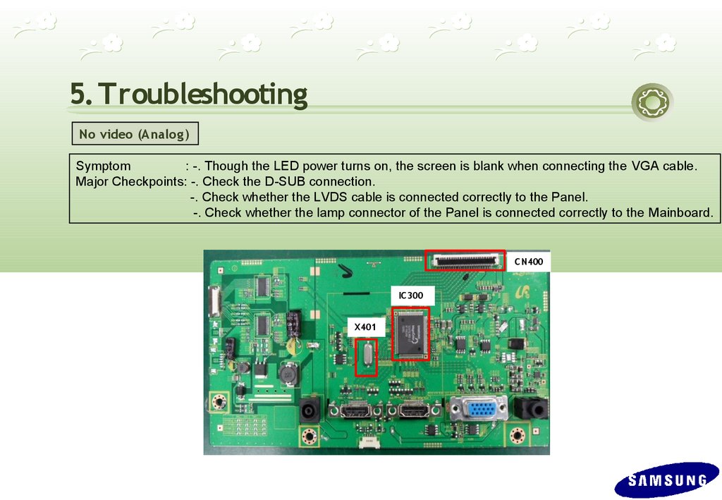
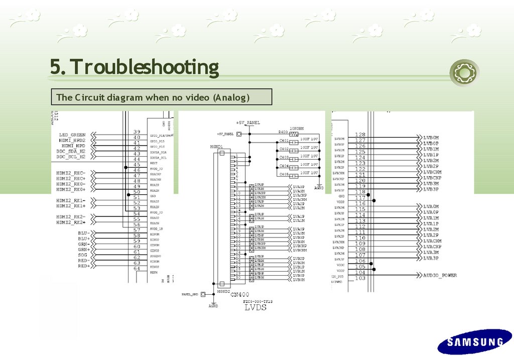
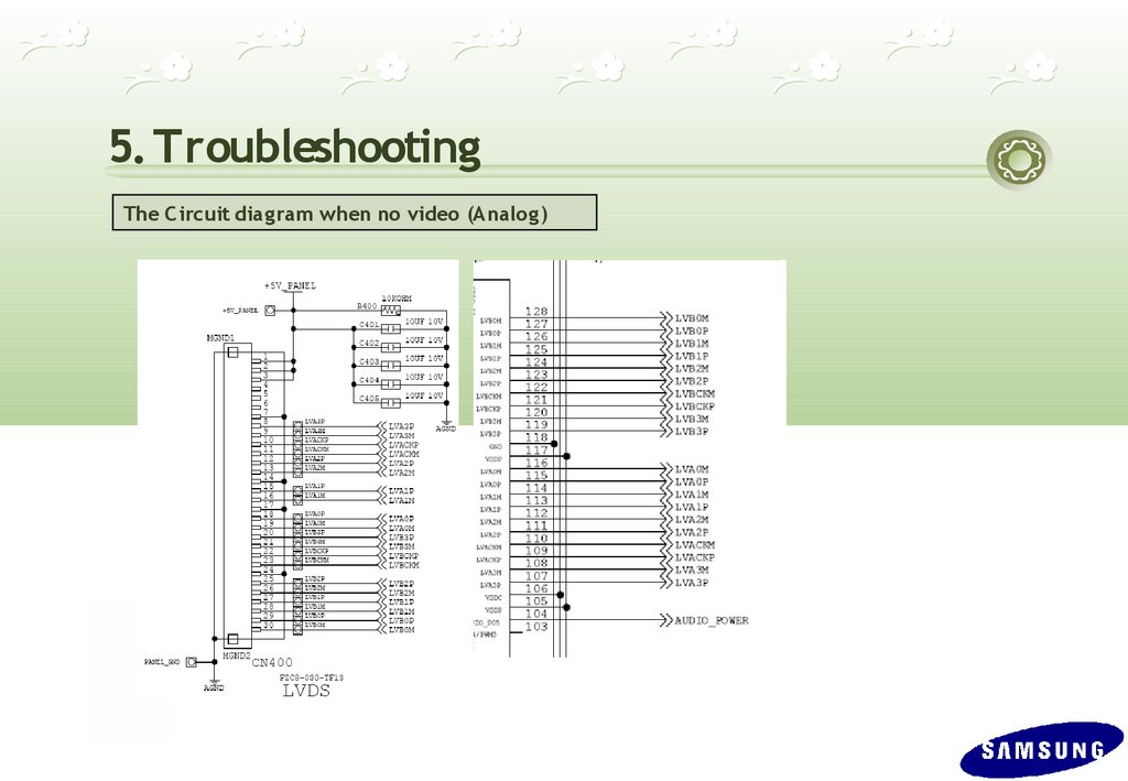
5. TroubleshootingNo video (Analog )
Symptom
: -. Though the LED power turns on, the screen is blank when connecting the VGA cable.
Major Checkpoints: -. Check the D-SUB connection.
-. Check whether the LVDS cable is connected correctly to the Panel.
-. Check whether the lamp connector of the Panel is connected correctly to the Mainboard.
C N400
IC 300
X401
51.
5. TroubleshootingNo video (Analog )
C heck the s ignal cables and the
connections .
Is X401 os cillating
correctly?
1
NO
R eplace or check related circuit.
YE S
2
Do the R GB input
appear at R 106
R 110 R 113,?
NO
C heck Input part
YE S
D oes the Hs ync , 3
V sync input appear at
pin 66,67 of IC 400,
res pectively?
NO
C heck IC 400 and related circuit.
YE S
D o output s ignals
appear at pin 8 to 30 of
C N400?
NO
C heck C N400 and related circuit.
YE S
There are D C 5V at pin
1,2, and 3 of C N400?
YE S
R eplace LC D panel
NO
C heck +5V_P anel and B L_E N s ignal.
52.
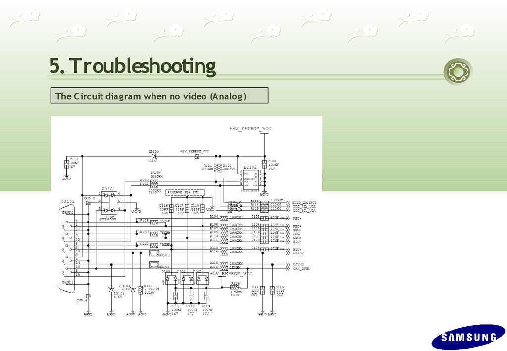
5. TroubleshootingThe C ircuit diag ram when no video (Analog )
53.
5. TroubleshootingThe C ircuit diag ram when no video (Analog )
54.
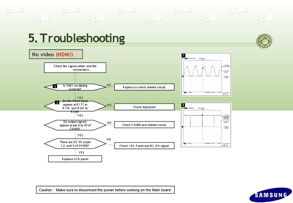
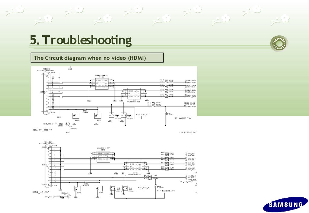
5. TroubleshootingNo video (HDMI)
Symptom
: -. Though the LED power turns on, the screen is blank when connecting the HDMI cable.
Major Checkpoints: -. Check the HDMI connection.
-. Check whether the LVDS cable is connected correctly to the Panel.
-. Check whether the lamp connector of the Panel is connected correctly to the LED Driver.
C N400
IC 300
X401
55.
5. TroubleshootingNo video (HDM I)
C heck the s ignal cables and the
connections .
Is X401 os cillating
correctly?
1
2
YE S
Do the HDM I input
appear at R 171 to
R 176 and R 241 to
R 246?
YE S
D o output s ignals
appear at pin 8 to 30 of
C N400?
NO
NO
NO
R eplace or check related circuit.
C heck Input part
C heck C N400 and related circuit.
YE S
There are D C 5V at pin
1,2, and 3 of C N400?
NO
C heck +5V_P anel and B L_E N s ignal.
YE S
R eplace LC D panel
Caution : Make sure to disconnect the power before working on the Main board.
56.
5. TroubleshootingThe C ircuit diag ram when no video (HDM I)
57.
5. TroubleshootingThe C ircuit diag ram when no video (Analog )
58.
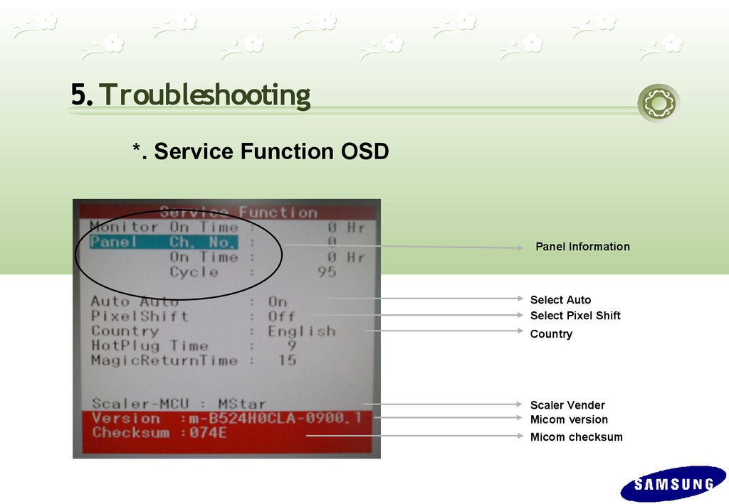
5. Troubleshooting*. Service Function OSD
Panel Information
Select Auto
Select Pixel Shift
Country
Scaler Vender
Micom version
Micom checksum
59.
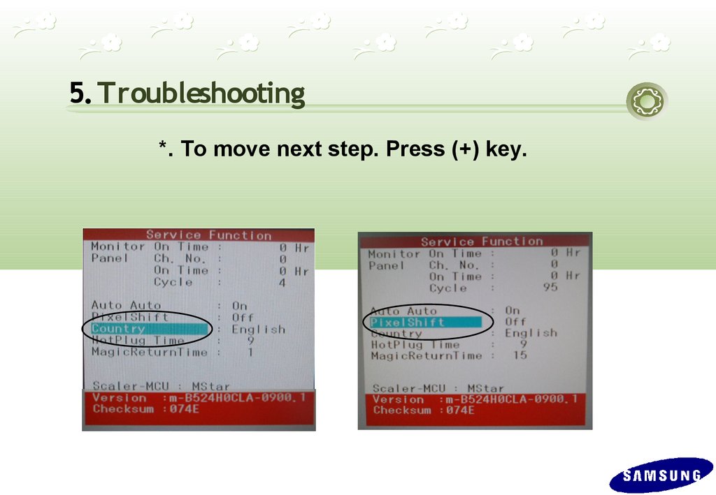
5. Troubleshooting*. To move next step. Press (+) key.
60.
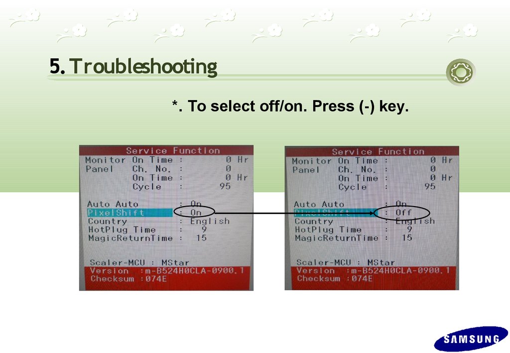
5. Troubleshooting*. To select off/on. Press (-) key.
61.
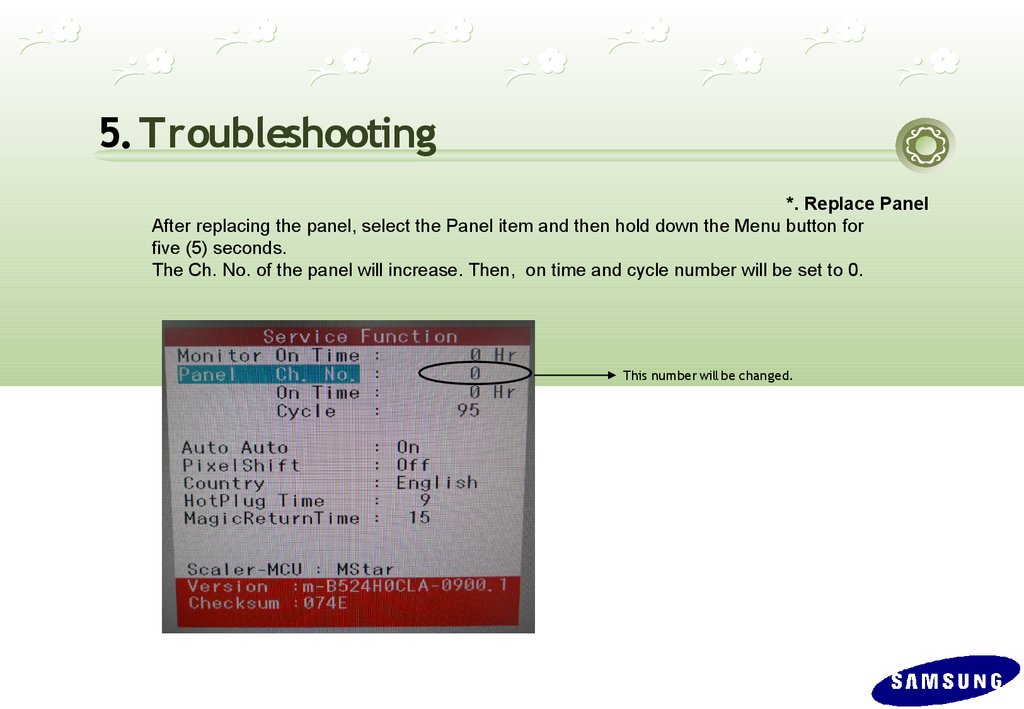
5. Troubleshooting*. Replace Panel
After replacing the panel, select the Panel item and then hold down the Menu button for
five (5) seconds.
The Ch. No. of the panel will increase. Then, on time and cycle number will be set to 0.
This number will be changed.
62.
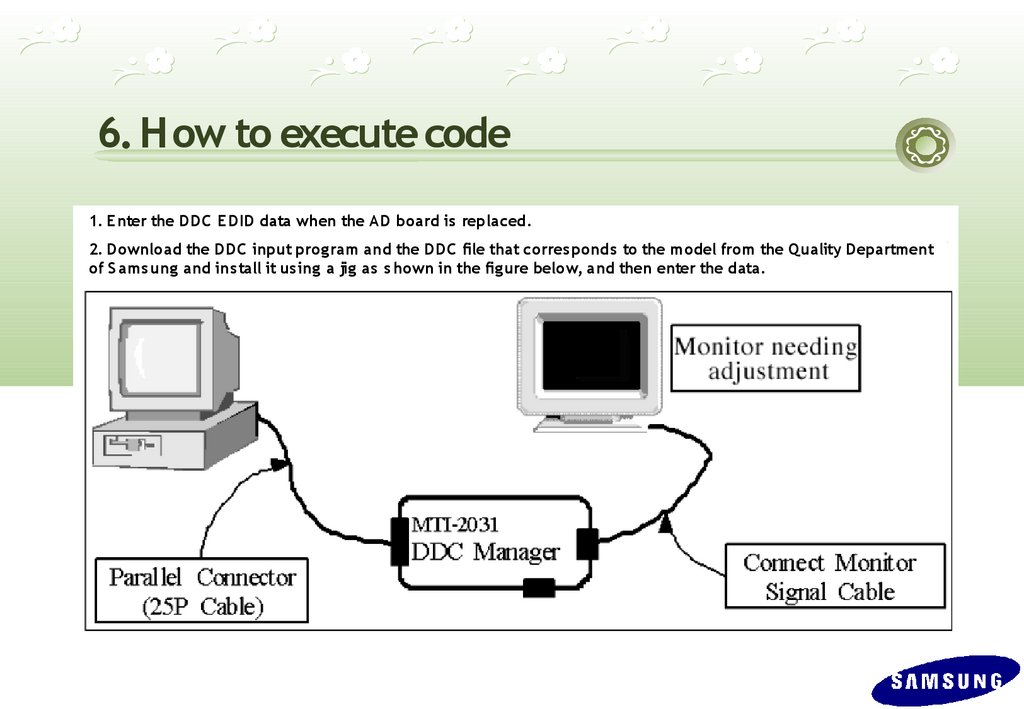
6. How to execute code1. E nter the DDC EDID data when the AD board is replaced.
2. Download the DDC input prog ram and the DDC file that corres ponds to the model from the Quality Department
of S ams ung and ins tall it us ing a jig as s hown in the fig ure below, and then enter the data.
C N703
63.
6. How to execute code (DDC )1
3
2
4
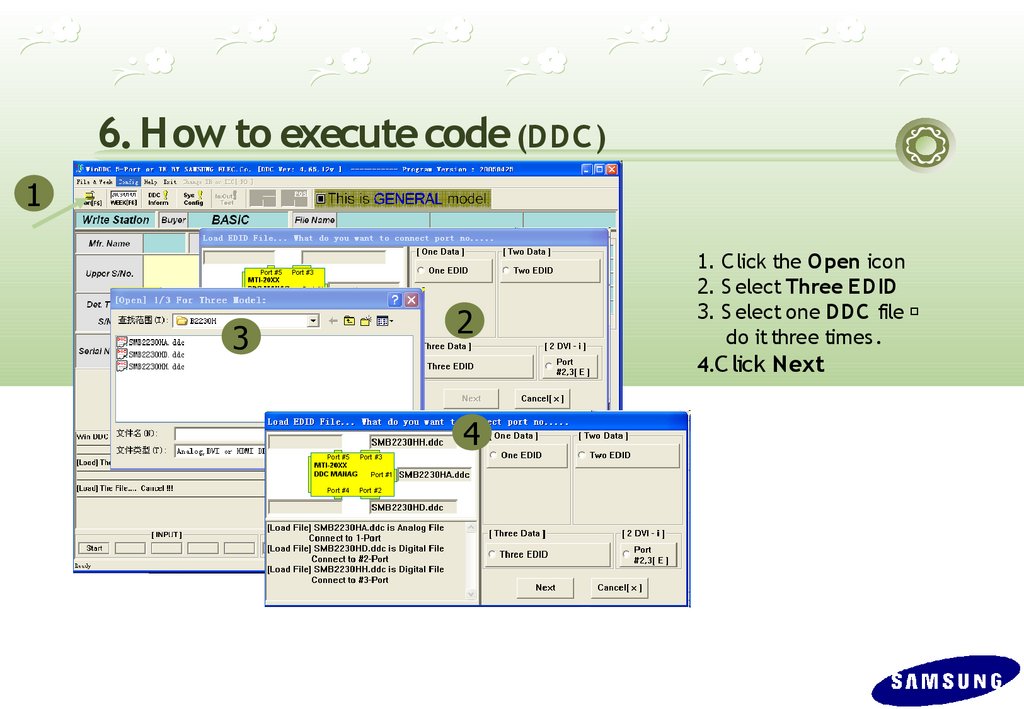
1. C lick the Open icon
2. S elect Three E DID
3. S elect one DDC file
do it three times .
4.C lick Next
64.
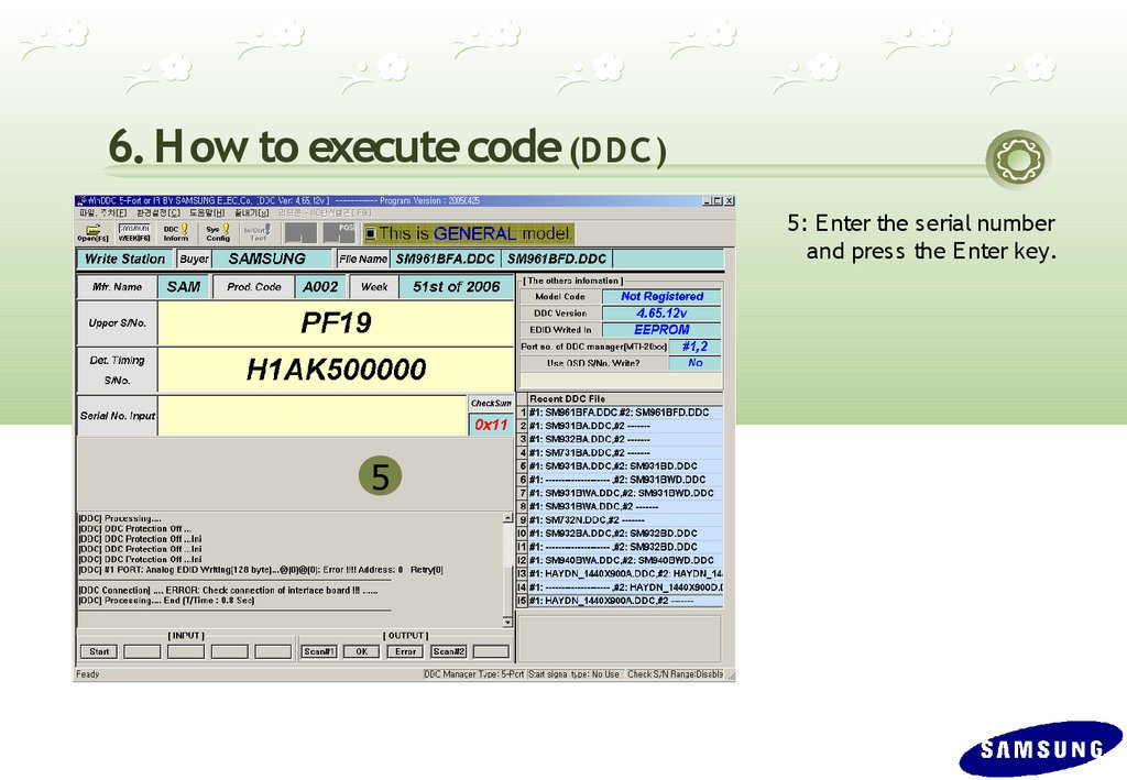
6. How to execute code (DDC )5: E nter the serial number
and pres s the E nter key.
5
65.
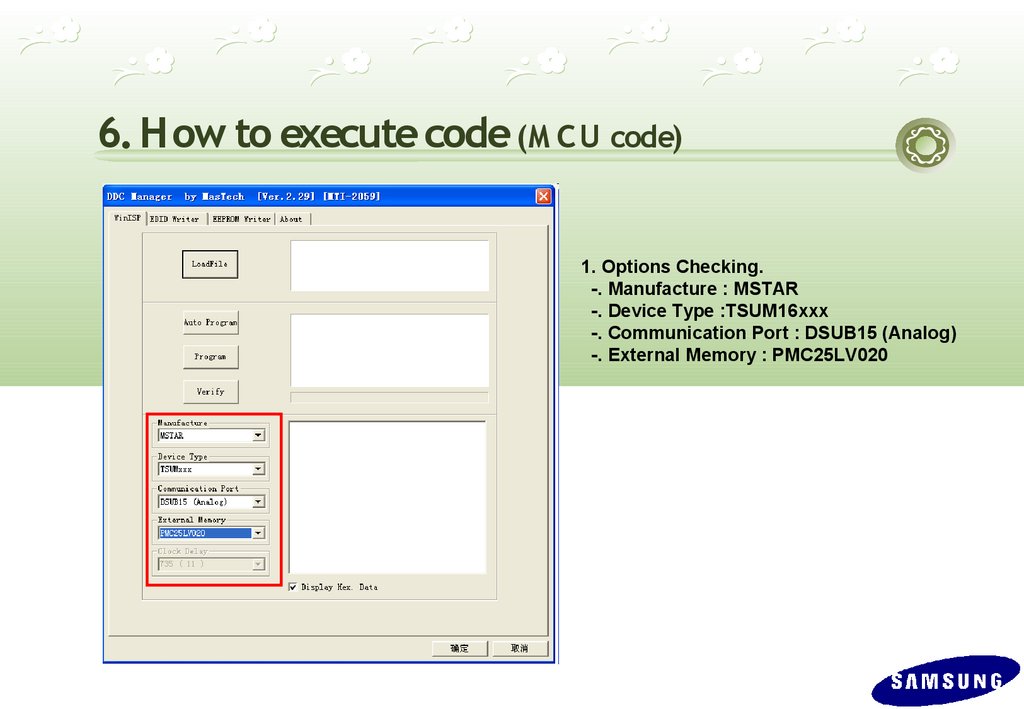
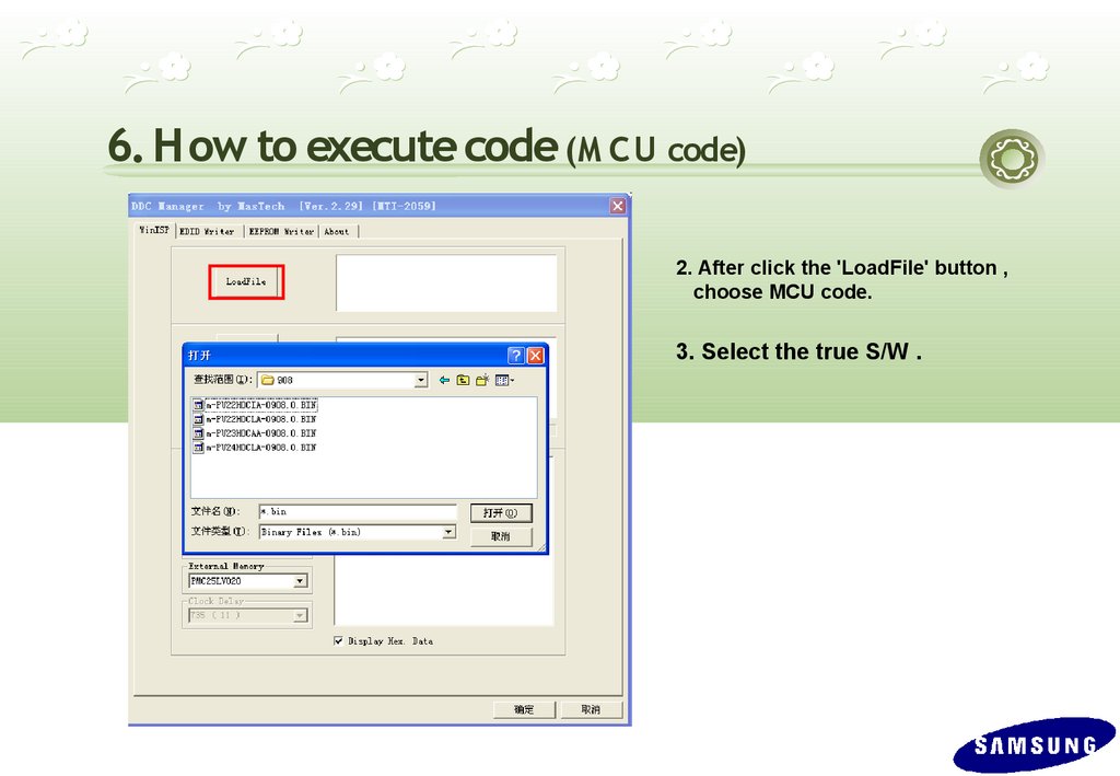
6. How to execute code (M C U code)1. Options Checking.
-. Manufacture : MSTAR
-. Device Type :TSUM16xxx
-. Communication Port : DSUB15 (Analog)
-. External Memory : PMC25LV020
66.
6. How to execute code (M C U code)2. After click the 'LoadFile' button ,
choose MCU code.
3. Select the true S/W .
67.
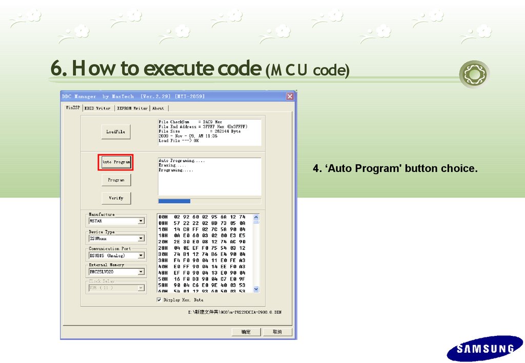
6. How to execute code (M C U code)4. ‘Auto Program' button choice.
68.
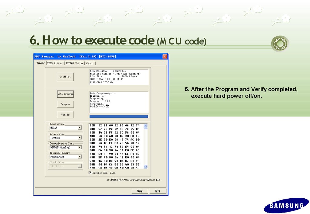
6. How to execute code (M C U code)5. After the Program and Verify completed,
execute hard power off/on.
69.
7. etc. (After replacing M ain PBA)You have to
E D ID input (Analog and HD M I)
Firmware install – M IC O M S /W input(use
D D C manager)
P C Auto C olor Adjust
-.select language “E nglish” in O S D , then
hold
down E nter key for 5 seconds
Factory R eset
-.setting to C ontrast and B rightness ‘0’.
-.P us h the E nter more than 5 seconds
-.select R eset.