


 electronics
Similar presentations:


Service Manual No-Frost
1.
Service ManualNo-Frost
Combi-Refrigerator
Models:
FR-417W
FR-417S
FR-415W
FR-415S
2. CONTENTS
1. SPECIFICATIONS2. EXTERNAL VIEW
3. EXTERNAL PARTS LIST
4. MACHINE ROOM VIEW
5. REFRIGERANT CYCLE
6. TEMPERATURES DIAGRAMS
7. WIRING DIAGRAMS
8. PCB CIRCUIT DIAGRAMS
9. COMPONENTS DISASSEMBLY PICTURES
10. DOOR POSITION CHANGE PROCESS
11. EXPLODE DRAWING
12. PARTS LIST
13. PCB CONTROL FUNCTION
1
3.
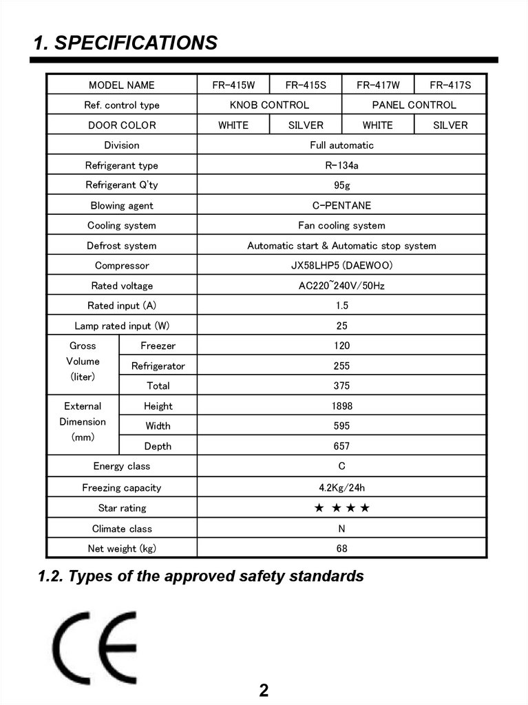
1. SPECIFICATIONSMODEL NAME
Ref. control type
DOOR COLOR
FR-415W
FR-415S
FR-417W
KNOB CONTROL
WHITE
FR-417S
PANEL CONTROL
SILVER
WHITE
SILVER
Division
Full automatic
Refrigerant type
R-134a
Refrigerant Q’ty
95g
Blowing agent
C-PENTANE
Cooling system
Fan cooling system
Defrost system
Automatic start & Automatic stop system
Compressor
JX58LHP5 (DAEWOO)
Rated voltage
AC220~240V/50Hz
Rated input (A)
1.5
Lamp rated input (W)
25
Gross
Volume
(liter)
External
Dimension
(mm)
Freezer
120
Refrigerator
255
Total
375
Height
1898
Width
595
Depth
657
Energy class
C
Freezing capacity
4.2Kg/24h
Star rating
★ ★★★
Climate class
N
Net weight (kg)
68
1.2. Types of the approved safety standards
2
4.
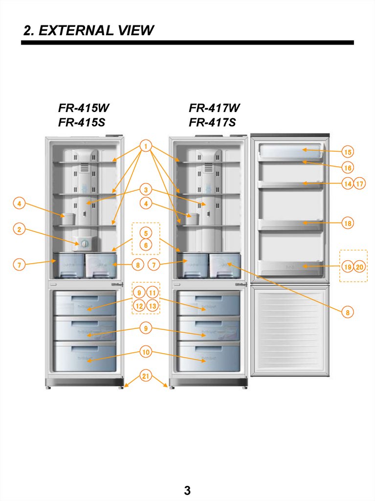
2. EXTERNAL VIEWFR-415W
FR-415S
FR-417W
FR-417S
1
15
16
14 17
3
4
4
18
2
5
6
7
8
7
9
11
19 20
12 13
8
9
10
21
3
5.
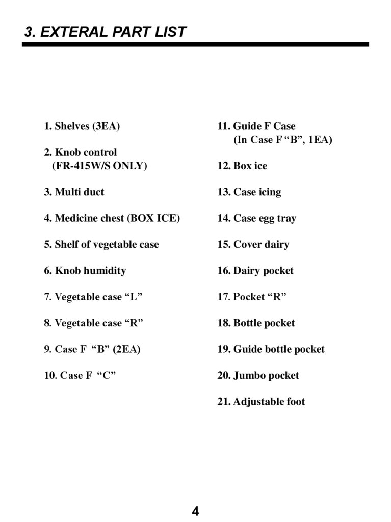
3. EXTERAL PART LIST1. Shelves (3EA)
11. Guide F Case
(In Case F “B”, 1EA)
2. Knob control
(FR-415W/S ONLY)
12. Box ice
3. Multi duct
13. Case icing
4. Medicine chest (BOX ICE)
14. Case egg tray
5. Shelf of vegetable case
15. Cover dairy
6. Knob humidity
16. Dairy pocket
7. Vegetable case “L”
17. Pocket “R”
8. Vegetable case “R”
18. Bottle pocket
9. Case F “B” (2EA)
19. Guide bottle pocket
10. Case F “C”
20. Jumbo pocket
21. Adjustable foot
4
6.
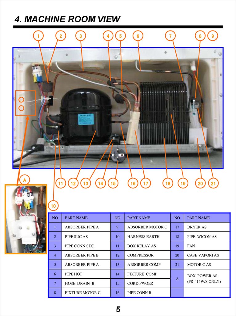
4. MACHINE ROOM VIEW1
2
A
11
3
12
4
13
14
5
15
6
16
7
17
18
19
8
9
20
21
10
NO
PART NAME
NO
PART NAME
NO
PART NAME
1
ABSORBER PIPE A
9
ABSORBER MOTOR C
17
DRYER AS
2
PIPE SUC AS
10
HARNESS EARTH
18
PIPE WICON AS
3
PIPE CONN SUC
11
BOX RELAY AS
19
FAN
4
ABSORBER PIPE B
12
COMPRESSOR
20
CASE VAPORI AS
5
ABSORBER PIPE A
13
ABSORBER COMP
21
MOTOR C AS
6
PIPE HOT
14
FIXTURE COMP
A
BOX POWER AS
(FR-415W/S ONLY)
7
HOSE DRAIN B
15
CORD PWOER
8
FIXTURE MOTOR C
16
PIPE CONN B
5
7.
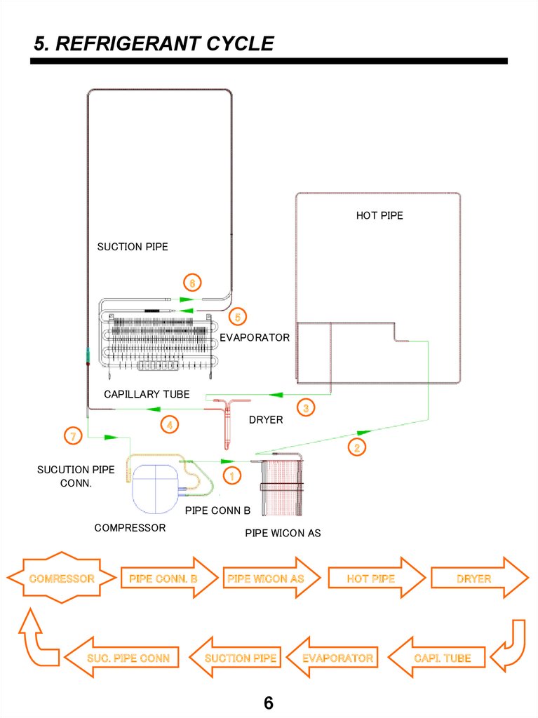
5. REFRIGERANT CYCLEHOT PIPE
SUCTION PIPE
6
5
EVAPORATOR
CAPILLARY TUBE
3
DRYER
4
7
2
SUCUTION PIPE
CONN.
1
PIPE CONN B
COMPRESSOR
COMRESSOR
PIPE CONN. B
SUC. PIPE CONN
PIPE WICON AS
PIPE WICON AS
SUCTION PIPE
6
HOT PIPE
EVAPORATOR
DRYER
CAPI. TUBE
8.
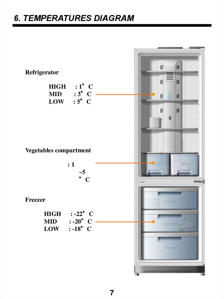
6. TEMPERATURES DIAGRAMRefrigerator
HIGH
MID
LOW
: 1°C
: 3°C
: 5°C
Vegetables compartment
:1
~5
°C
Freezer
HIGH
MID
LOW
: -22°C
: -20°C
: -18°C
7
9.
7. WIRING DIAGRAMS7.1. FR-417W/S
8
10.
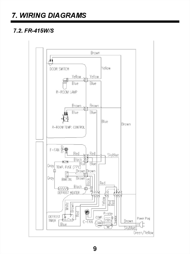
7. WIRING DIAGRAMS7.2. FR-415W/S
9
11.
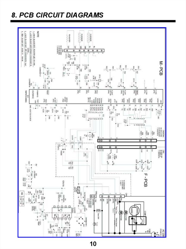
8. PCB CIRCUIT DIAGRAMS10
12.
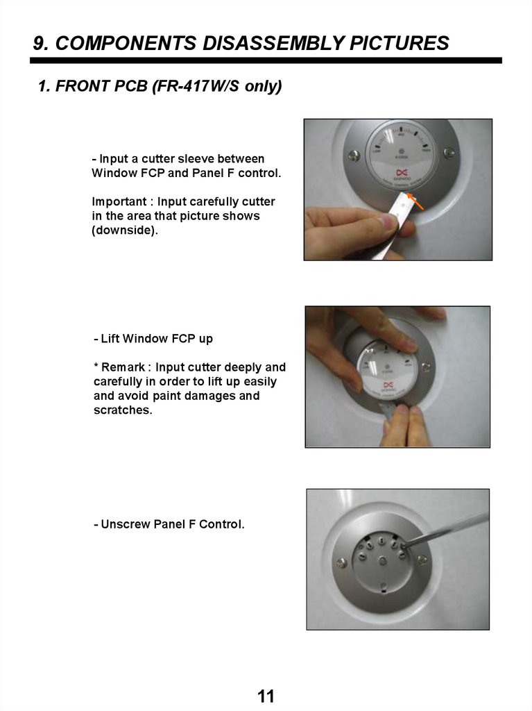
9. COMPONENTS DISASSEMBLY PICTURES1. FRONT PCB (FR-417W/S only)
- Input a cutter sleeve between
Window FCP and Panel F control.
Important : Input carefully cutter
in the area that picture shows
(downside).
- Lift Window FCP up
* Remark : Input cutter deeply and
carefully in order to lift up easily
and avoid paint damages and
scratches.
- Unscrew Panel F Control.
11
13.
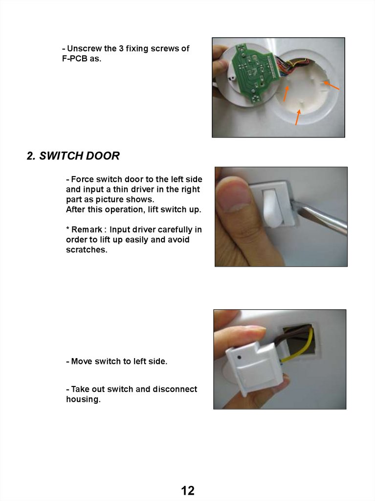
- Unscrew the 3 fixing screws ofF-PCB as.
2. SWITCH DOOR
- Force switch door to the left side
and input a thin driver in the right
part as picture shows.
After this operation, lift switch up.
* Remark : Input driver carefully in
order to lift up easily and avoid
scratches.
- Move switch to left side.
- Take out switch and disconnect
housing.
12
14.
3. M-PCB(FR-417W/S only)- Unscrew the 3 fixing screws of
cover PCB box.
- Disconnect all housings
connectors from M-PCB, and
force plastic locker of PCB box in
order to take out the PCB.
* Remake: In FR-417W/S models
forced defrost button is located in
M-PCB, so PCB box cover must
be disassembled.
4. RELAY BOX COVER
- Press relay box cover stopper
sleeve with a minus driver like
picture shows.
13
15.
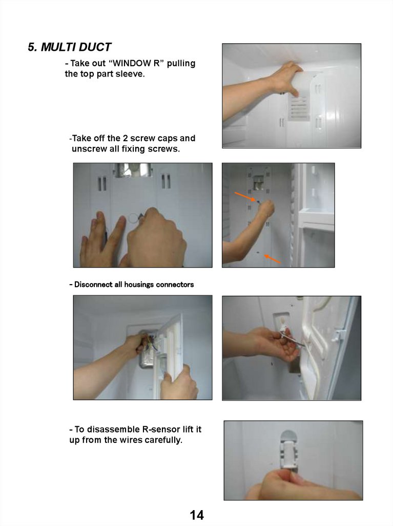
5. MULTI DUCT- Take out “WINDOW R” pulling
the top part sleeve.
-Take off the 2 screw caps and
unscrew all fixing screws.
- Disconnect all housings connectors
- To disassemble R-sensor lift it
up from the wires carefully.
14
16.
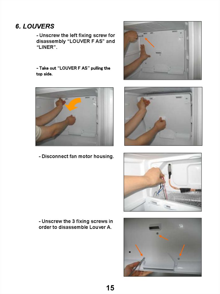
6. LOUVERS- Unscrew the left fixing screw for
disassembly “LOUVER F AS” and
“LINER”.
- Take out “LOUVER F AS” pulling the
top side.
- Disconnect fan motor housing.
- Unscrew the 3 fixing screws in
order to disassemble Louver A.
15
17.
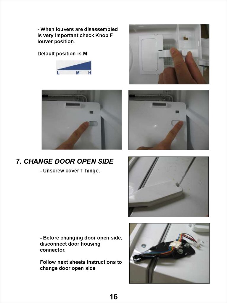
- When louvers are disassembledis very important check Knob F
louver position.
Default position is M
7. CHANGE DOOR OPEN SIDE
- Unscrew cover T hinge.
- Before changing door open side,
disconnect door housing
connector.
Follow next sheets instructions to
change door open side
16
18.
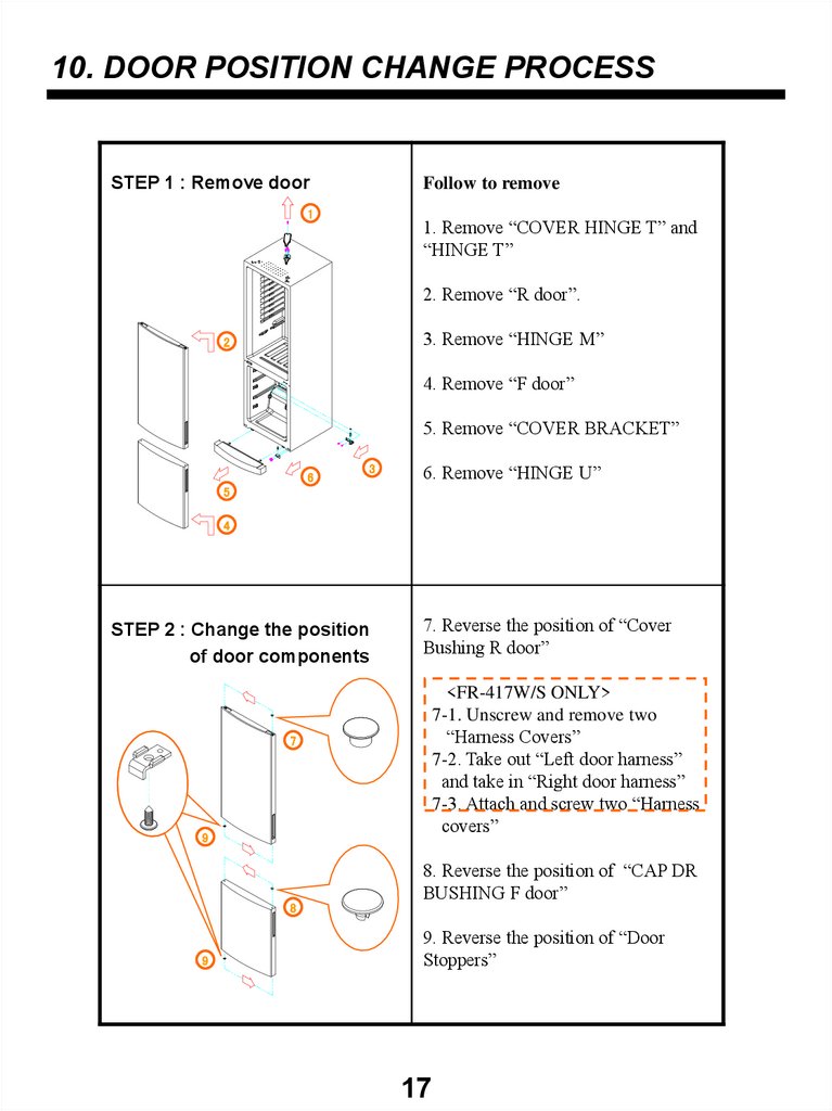
10. DOOR POSITION CHANGE PROCESSSTEP 1 : Remove door
Follow to remove
1
1. Remove “COVER HINGE T” and
“HINGE T”
2. Remove “R door”.
3. Remove “HINGE M”
2
4. Remove “F door”
5. Remove “COVER BRACKET”
6
3
6. Remove “HINGE U”
5
4
STEP 2 : Change the position
of door components
7. Reverse the position of “Cover
Bushing R door”
<FR-417W/S ONLY>
7-1. Unscrew and remove two
“Harness Covers”
7-2. Take out “Left door harness”
and take in “Right door harness”
7-3. Attach and screw two “Harness
covers”
7
9
8
9
8. Reverse the position of “CAP DR
BUSHING F door”
9. Reverse the position of “Door
Stoppers”
17
19.
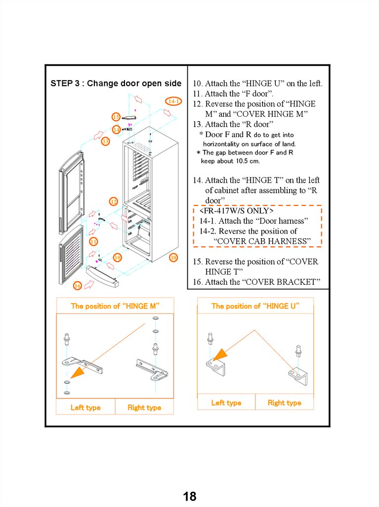
STEP 3 : Change door open side14-1
15
14
10. Attach the “HINGE U” on the left.
11. Attach the “F door”.
12. Reverse the position of “HINGE
M” and “COVER HINGE M”
13. Attach the “R door”
* Door F and R do to get into
13
horizontality on surface of land.
* The gap between door F and R
keep about 10.5 cm.
14. Attach the “HINGE T” on the left
of cabinet after assembling to “R
door”
<FR-417W/S ONLY>
14-1. Attach the “Door harness”
14-2. Reverse the position of
“COVER CAB HARNESS”
12
11
10
10
16
15. Reverse the position of “COVER
HINGE T”
16. Attach the “COVER BRACKET”
The position of “HINGE M”
Left type
The position of “HINGE U”
Left type
Right type
18
Right type
20.
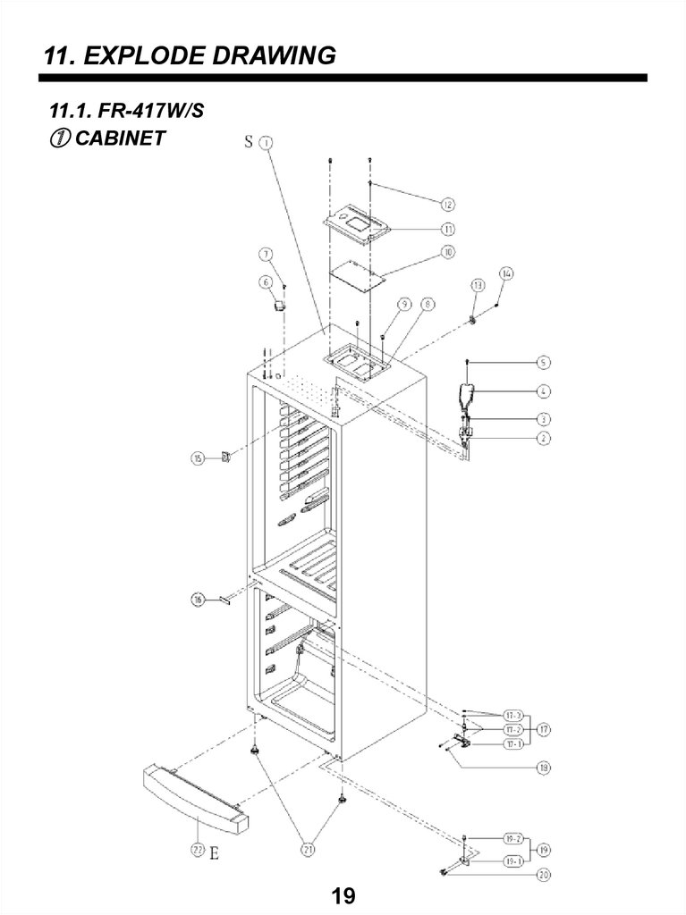
11. EXPLODE DRAWING11.1. FR-417W/S
① CABINET
19
21.
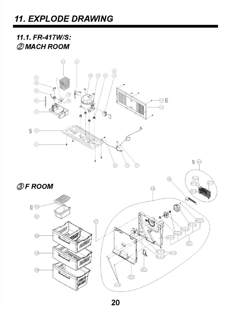
11. EXPLODE DRAWING11.1. FR-417W/S:
② MACH ROOM
③ F ROOM
20
22.
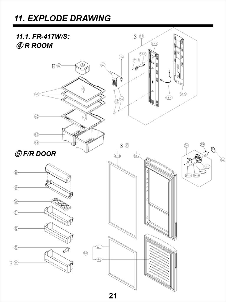
11. EXPLODE DRAWING11.1. FR-417W/S:
④ R ROOM
⑤ F/R DOOR
21
23.
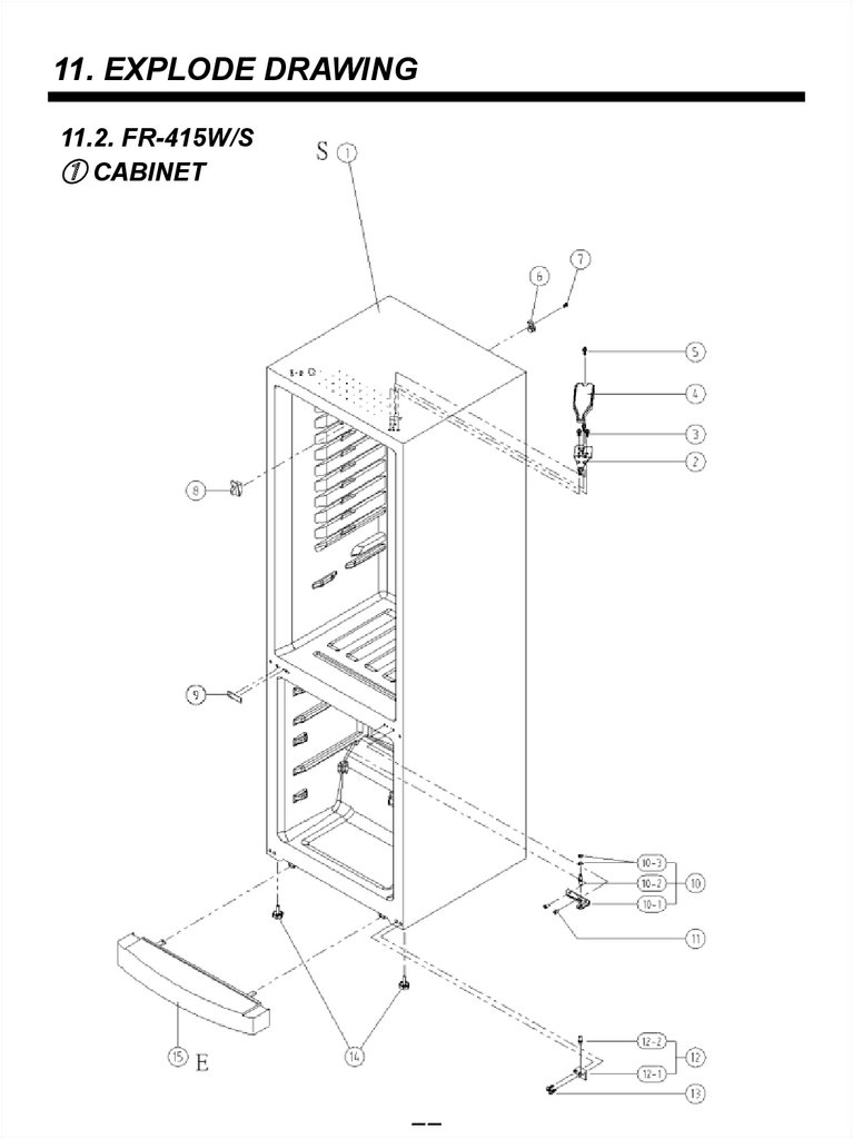
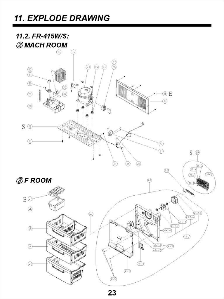
11. EXPLODE DRAWING11.2. FR-415W/S
① CABINET
22
24.
11. EXPLODE DRAWING11.2. FR-415W/S:
② MACH ROOM
③ F ROOM
23
25.
11. EXPLODE DRAWING11.2. FR-415W/S:
④ R ROOM
⑤ F/R DOOR
24
26.
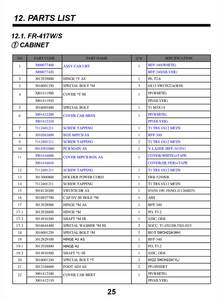
12. PARTS LIST12.1. FR-417W/S
① CABINET
NO
PART CODE
1
3000077400
PART NAME
ASSY CAB URT
Q’ty
1
3000077420
SEPCIFICATION
RFP-340(WHITE)
RFP-340(SILVER)
2
3012929000
HINGE *T AS
1
P0, T2.6
3
3016001250
SPECIAL BOLT *M
3
6X15 SWCH22A(WH)
4
3001411900
COVER *T HI
1
PP(WHITE)
3001411910
PP(SILVER)
5
3016003400
SPECIAL BOLT
1
T1 M5X14
6
3001412200
COVER CAB HRNS
1
PP(WHITE)
3001412210
PP(SILVER)
7
7112401211
SCREW TAPPING
1
T1 TRS 4X12 MFZN
8
3010563800
BOX M/PCB AS
1
RFP-340
9
7112401211
SCREW TAPPING
2
T1 TRS 4X12 MFZN
10
30143G1060
PCB MAIN AS
1
V-LAZER (RFP-341SV)
11
3001416600
COVER M/PCB BOX AS
1
COVER(WHITE)+TAPE
3001416610
COVER(SILVER)+TAPE
12
7112401211
SCREW TAPPING
1
T1 TRS 4X12 MFZN
13
3013000800
HOLDER POWER CORD
1
FRB-5250NB
14
7112401211
SCREW TAPPING
1
T1 TRS 4X12 MFZN
15
3018120200
SWITCH DR AS
1
83430-109-19(NO.411260025)
16
3010937700
CAP DV HI HOLE *M
1
ABS
17
3012928900
HINGE *M AS
1
RFP-340
17-1
3012928600
HINGE *M
1
PO, T3.2
17-2
3014910300
SHAFT *M HI
1
S20C, OD8
17-3
3016044400
SPECIAL WASHER *M HI
2
SGCC, T1.0XI.D8.5XO.D15
18
3016001250
SPECIAL BOLT *M
2
6X15 SWCH22A(WH)
19
3012929100
HINGE *U AS
1
RFP-340
19-1
3012928800
HINGE *U
1
PO, T3.2
19-2
3014910500
SHAFT *U HI
1
S20C, OD8
20
3016001240
SPECIAL BOLT *T
2
6X22 SWCH22A(YL)
21
3012104600
FOOT ADJ AS
2
PP+INSERT
22
3001412100
COVER CAB BRKT
1
PP(WHITE)
3001412110
PP(SILVER)
25
27.
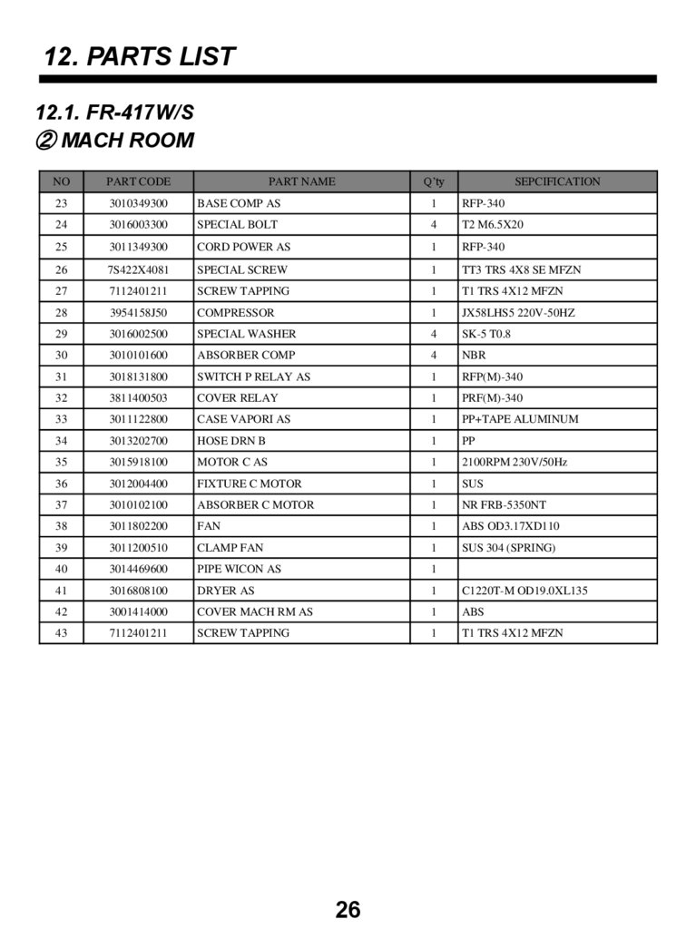
12. PARTS LIST12.1. FR-417W/S
② MACH ROOM
PART NAME
Q’ty
NO
PART CODE
23
3010349300
BASE COMP AS
1
RFP-340
24
3016003300
SPECIAL BOLT
4
T2 M6.5X20
25
3011349300
CORD POWER AS
1
RFP-340
26
7S422X4081
SPECIAL SCREW
1
TT3 TRS 4X8 SE MFZN
27
7112401211
SCREW TAPPING
1
T1 TRS 4X12 MFZN
28
3954158J50
COMPRESSOR
1
JX58LHS5 220V-50HZ
29
3016002500
SPECIAL WASHER
4
SK-5 T0.8
30
3010101600
ABSORBER COMP
4
NBR
31
3018131800
SWITCH P RELAY AS
1
RFP(M)-340
32
3811400503
COVER RELAY
1
PRF(M)-340
33
3011122800
CASE VAPORI AS
1
PP+TAPE ALUMINUM
34
3013202700
HOSE DRN B
1
PP
35
3015918100
MOTOR C AS
1
2100RPM 230V/50Hz
36
3012004400
FIXTURE C MOTOR
1
SUS
37
3010102100
ABSORBER C MOTOR
1
NR FRB-5350NT
38
3011802200
FAN
1
ABS OD3.17XD110
39
3011200510
CLAMP FAN
1
SUS 304 (SPRING)
40
3014469600
PIPE WICON AS
1
41
3016808100
DRYER AS
1
C1220T-M OD19.0XL135
42
3001414000
COVER MACH RM AS
1
ABS
43
7112401211
SCREW TAPPING
1
T1 TRS 4X12 MFZN
26
SEPCIFICATION
28.
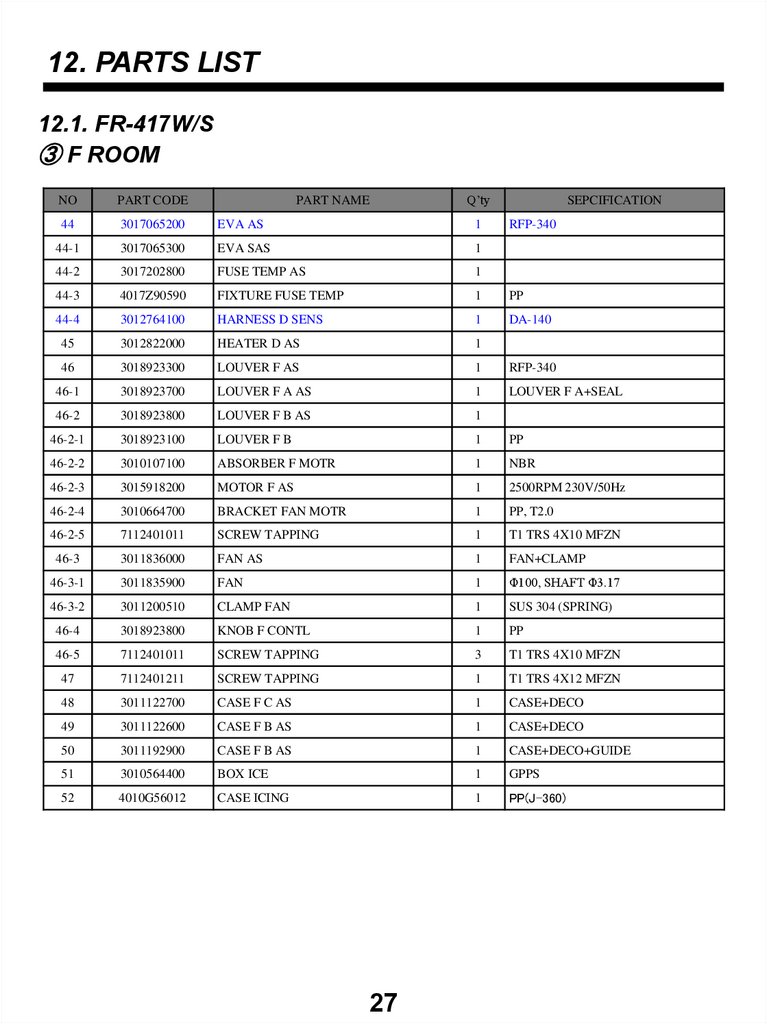
12. PARTS LIST12.1. FR-417W/S
③ F ROOM
PART NAME
Q’ty
NO
PART CODE
44
3017065200
EVA AS
1
44-1
3017065300
EVA SAS
1
44-2
3017202800
FUSE TEMP AS
1
44-3
4017Z90590
FIXTURE FUSE TEMP
1
PP
44-4
3012764100
HARNESS D SENS
1
DA-140
45
3012822000
HEATER D AS
1
46
3018923300
LOUVER F AS
1
RFP-340
46-1
3018923700
LOUVER F A AS
1
LOUVER F A+SEAL
46-2
3018923800
LOUVER F B AS
1
46-2-1
3018923100
LOUVER F B
1
PP
46-2-2
3010107100
ABSORBER F MOTR
1
NBR
46-2-3
3015918200
MOTOR F AS
1
2500RPM 230V/50Hz
46-2-4
3010664700
BRACKET FAN MOTR
1
PP, T2.0
46-2-5
7112401011
SCREW TAPPING
1
T1 TRS 4X10 MFZN
46-3
3011836000
FAN AS
1
FAN+CLAMP
46-3-1
3011835900
FAN
1
Φ100, SHAFT Φ3.17
46-3-2
3011200510
CLAMP FAN
1
SUS 304 (SPRING)
46-4
3018923800
KNOB F CONTL
1
PP
46-5
7112401011
SCREW TAPPING
3
T1 TRS 4X10 MFZN
47
7112401211
SCREW TAPPING
1
T1 TRS 4X12 MFZN
48
3011122700
CASE F C AS
1
CASE+DECO
49
3011122600
CASE F B AS
1
CASE+DECO
50
3011192900
CASE F B AS
1
CASE+DECO+GUIDE
51
3010564400
BOX ICE
1
GPPS
52
4010G56012
CASE ICING
1
PP(J-360)
27
SEPCIFICATION
RFP-340
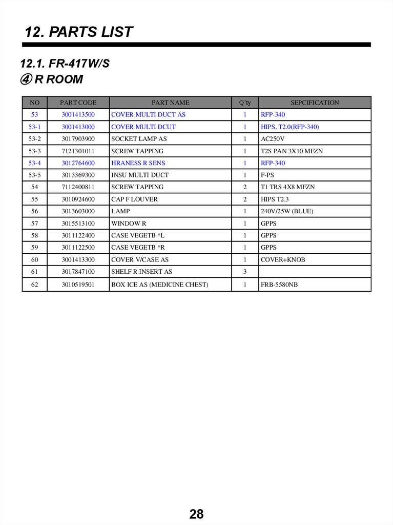
29.
12. PARTS LIST12.1. FR-417W/S
④ R ROOM
PART NAME
Q’ty
NO
PART CODE
53
3001413500
COVER MULTI DUCT AS
1
RFP-340
53-1
3001413000
COVER MULTI DCUT
1
HIPS, T2.0(RFP-340)
53-2
3017903900
SOCKET LAMP AS
1
AC250V
53-3
7121301011
SCREW TAPPING
1
T2S PAN 3X10 MFZN
53-4
3012764600
HRANESS R SENS
1
RFP-340
53-5
3013369300
INSU MULTI DUCT
1
F-PS
54
7112400811
SCREW TAPPING
2
T1 TRS 4X8 MFZN
55
3010924600
CAP F LOUVER
2
HIPS T2.3
56
3013603000
LAMP
1
240V/25W (BLUE)
57
3015513100
WINDOW R
1
GPPS
58
3011122400
CASE VEGETB *L
1
GPPS
59
3011122500
CASE VEGETB *R
1
GPPS
60
3001413300
COVER V/CASE AS
1
COVER+KNOB
61
3017847100
SHELF R INSERT AS
3
62
3010519501
BOX ICE AS (MEDICINE CHEST)
1
28
SEPCIFICATION
FRB-5580NB
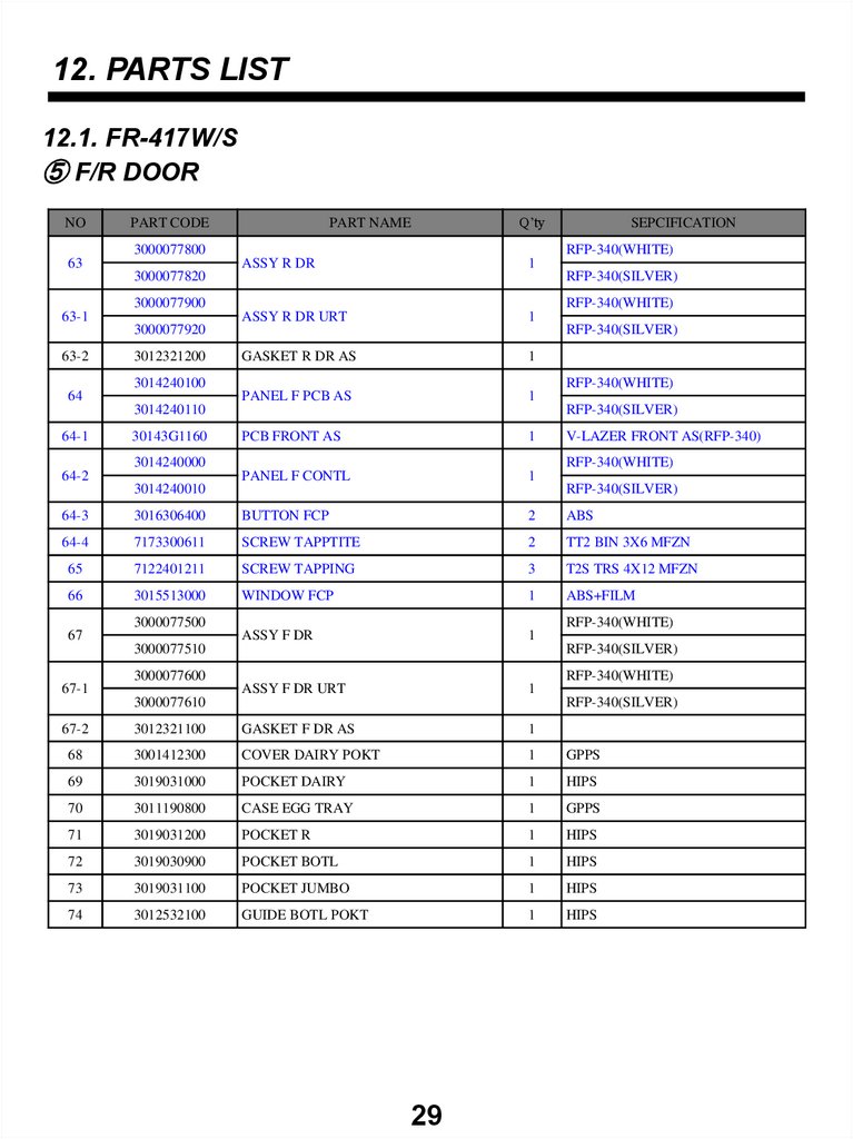
30.
12. PARTS LIST12.1. FR-417W/S
⑤ F/R DOOR
NO
PART CODE
PART NAME
Q’ty
3000077800
63
RFP-340(WHITE)
ASSY R DR
1
3000077820
RFP-340(SILVER)
3000077900
63-1
RFP-340(WHITE)
ASSY R DR URT
1
3000077920
63-2
3012321200
RFP-340(SILVER)
GASKET R DR AS
1
PANEL F PCB AS
1
3014240100
64
RFP-340(WHITE)
3014240110
64-1
30143G1160
RFP-340(SILVER)
PCB FRONT AS
1
PANEL F CONTL
1
3014240000
64-2
SEPCIFICATION
V-LAZER FRONT AS(RFP-340)
RFP-340(WHITE)
3014240010
RFP-340(SILVER)
64-3
3016306400
BUTTON FCP
2
ABS
64-4
7173300611
SCREW TAPPTITE
2
TT2 BIN 3X6 MFZN
65
7122401211
SCREW TAPPING
3
T2S TRS 4X12 MFZN
66
3015513000
WINDOW FCP
1
ABS+FILM
ASSY F DR
1
3000077500
67
RFP-340(WHITE)
3000077510
RFP-340(SILVER)
3000077600
67-1
RFP-340(WHITE)
ASSY F DR URT
1
3000077610
RFP-340(SILVER)
67-2
3012321100
GASKET F DR AS
1
68
3001412300
COVER DAIRY POKT
1
GPPS
69
3019031000
POCKET DAIRY
1
HIPS
70
3011190800
CASE EGG TRAY
1
GPPS
71
3019031200
POCKET R
1
HIPS
72
3019030900
POCKET BOTL
1
HIPS
73
3019031100
POCKET JUMBO
1
HIPS
74
3012532100
GUIDE BOTL POKT
1
HIPS
29
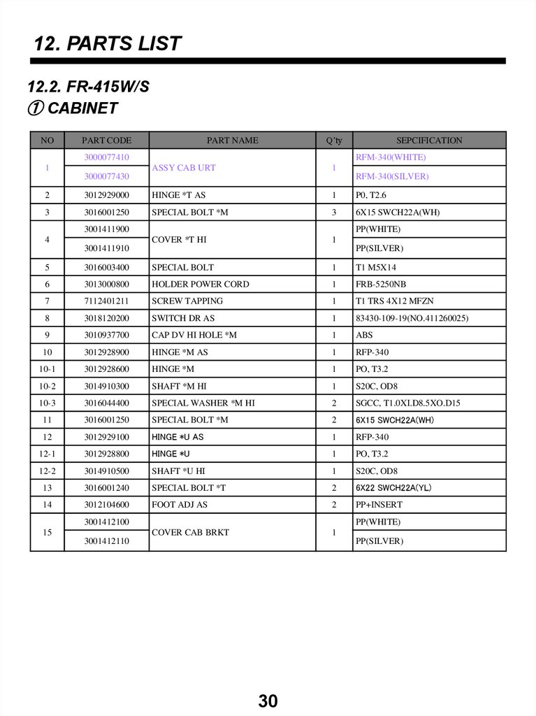
31.
12. PARTS LIST12.2. FR-415W/S
① CABINET
NO
PART CODE
PART NAME
Q’ty
3000077410
1
SEPCIFICATION
RFM-340(WHITE)
ASSY CAB URT
1
3000077430
RFM-340(SILVER)
2
3012929000
HINGE *T AS
1
P0, T2.6
3
3016001250
SPECIAL BOLT *M
3
6X15 SWCH22A(WH)
COVER *T HI
1
3001411900
4
PP(WHITE)
3001411910
PP(SILVER)
5
3016003400
SPECIAL BOLT
1
T1 M5X14
6
3013000800
HOLDER POWER CORD
1
FRB-5250NB
7
7112401211
SCREW TAPPING
1
T1 TRS 4X12 MFZN
8
3018120200
SWITCH DR AS
1
83430-109-19(NO.411260025)
9
3010937700
CAP DV HI HOLE *M
1
ABS
10
3012928900
HINGE *M AS
1
RFP-340
10-1
3012928600
HINGE *M
1
PO, T3.2
10-2
3014910300
SHAFT *M HI
1
S20C, OD8
10-3
3016044400
SPECIAL WASHER *M HI
2
SGCC, T1.0XI.D8.5XO.D15
11
3016001250
SPECIAL BOLT *M
2
6X15 SWCH22A(WH)
12
3012929100
HINGE *U AS
1
RFP-340
12-1
3012928800
HINGE *U
1
PO, T3.2
12-2
3014910500
SHAFT *U HI
1
S20C, OD8
13
3016001240
SPECIAL BOLT *T
2
6X22 SWCH22A(YL)
14
3012104600
FOOT ADJ AS
2
PP+INSERT
COVER CAB BRKT
1
3001412100
15
PP(WHITE)
3001412110
PP(SILVER)
30
32.
12. PARTS LIST12.2. FR-415W/S
② MACH ROOM
PART NAME
Q’ty
NO
PART CODE
16
3010349300
BASE COMP AS
1
RFP-340
17
3016003300
SPECIAL BOLT
4
T2 M6.5X20
18
3011349300
CORD POWER AS
1
RFP-340
19
7S422X4081
SPECIAL SCREW
1
TT3 TRS 4X8 SE MFZN
20
7112401211
SCREW TAPPING
1
T1 TRS 4X12 MFZN
21
3010563900
BOX POWER AS
1
RFM-340
22
7112401211
SCREW TAPPING
2
T1 TRS 4X12 MFZN
23
3954158J50
COMPRESSOR
1
JX58LHS5 220V-50HZ
24
3016002500
SPECIAL WASHER
4
SK-5 T0.8
25
3010101600
ABSORBER COMP
4
NBR
26
3018131800
SWITCH P RELAY AS
1
RFP(M)-340
27
3811400503
COVER RELAY
1
PRF(M)-340
28
3011122800
CASE VAPORI AS
1
PP+TAPE ALUMINUM
29
3013202700
HOSE DRN B
1
PP
30
3015918100
MOTOR C AS
1
2100RPM 230V/50Hz
31
3012004400
FIXTURE C MOTOR
1
SUS
32
3010102100
ABSORBER C MOTOR
1
NR FRB-5350NT
33
3011802200
FAN
1
ABS OD3.17XD110
34
3011200510
CLAMP FAN
1
SUS 304 (SPRING)
35
3014469600
PIPE WICON AS
1
36
3016808100
DRYER AS
1
C1220T-M OD19.0XL135
37
3001414000
COVER MACH RM AS
1
ABS
38
7112401211
SCREW TAPPING
1
T1 TRS 4X12 MFZN
31
SEPCIFICATION
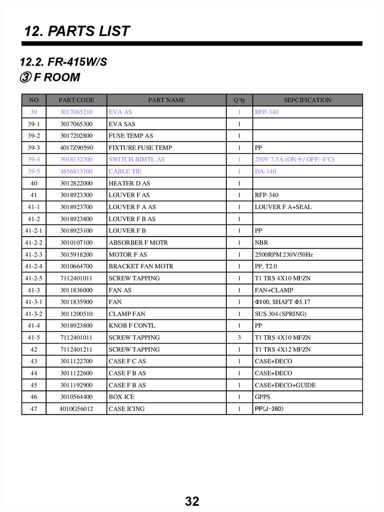
33.
12. PARTS LIST12.2. FR-415W/S
③ F ROOM
PART NAME
Q’ty
NO
PART CODE
39
3017065210
EVA AS
1
39-1
3017065300
EVA SAS
1
39-2
3017202800
FUSE TEMP AS
1
39-3
4017Z90590
FIXTURE FUSE TEMP
1
PP
39-4
3018132300
SWITCH BIMTL AS
1
250V 7.5A (ON:9 / OFF:-4℃)
39-5
4856813100
CABLE TIE
1
DA-140
40
3012822000
HEATER D AS
1
41
3018923300
LOUVER F AS
1
RFP-340
41-1
3018923700
LOUVER F A AS
1
LOUVER F A+SEAL
41-2
3018923800
LOUVER F B AS
1
41-2-1
3018923100
LOUVER F B
1
PP
41-2-2
3010107100
ABSORBER F MOTR
1
NBR
41-2-3
3015918200
MOTOR F AS
1
2500RPM 230V/50Hz
41-2-4
3010664700
BRACKET FAN MOTR
1
PP, T2.0
41-2-5
7112401011
SCREW TAPPING
1
T1 TRS 4X10 MFZN
41-3
3011836000
FAN AS
1
FAN+CLAMP
41-3-1
3011835900
FAN
1
Φ100, SHAFT Φ3.17
41-3-2
3011200510
CLAMP FAN
1
SUS 304 (SPRING)
41-4
3018923800
KNOB F CONTL
1
PP
41-5
7112401011
SCREW TAPPING
3
T1 TRS 4X10 MFZN
42
7112401211
SCREW TAPPING
1
T1 TRS 4X12 MFZN
43
3011122700
CASE F C AS
1
CASE+DECO
44
3011122600
CASE F B AS
1
CASE+DECO
45
3011192900
CASE F B AS
1
CASE+DECO+GUIDE
46
3010564400
BOX ICE
1
GPPS
47
4010G56012
CASE ICING
1
PP(J-360)
32
SEPCIFICATION
RFP-340
34.
12. PARTS LIST12.2. FR-415W/S
④ R ROOM
PART NAME
Q’ty
NO
PART CODE
48
3001413500
COVER MULTI DUCT AS
1
RFP-340
48-1
3001413000
COVER MULTI DCUT
1
HIPS, T2.0(RFP-340)
48-2
3017903900
SOCKET LAMP AS
1
AC250V
48-3
7121301011
SCREW TAPPING
1
T2S PAN 3X10 MFZN
48-4
3018305700
THERMOSTAT
1
RFM-340
48-5
3017903900
HARNESS THERMO AS
1
RFM-340
48-6
3013413600
KNOB R CONTL
1
HIPS
48-7
3013369300
INSU MULTI DUCT
1
F-PS
49
7112400811
SCREW TAPPING
2
T1 TRS 4X8 MFZN
50
3010924600
CAP F LOUVER
2
HIPS T2.3
51
3013603000
LAMP
1
240V/25W (BLUE)
52
3015513100
WINDOW R
1
GPPS
53
3011122400
CASE VEGETB *L
1
GPPS
54
3011122500
CASE VEGETB *R
1
GPPS
55
3001413300
COVER V/CASE AS
1
COVER+KNOB
56
3017847100
SHELF R INSERT AS
3
57
3010519501
BOX ICE AS (MEDICINE CHEST)
1
33
SEPCIFICATION
FRB-5580NB
35.
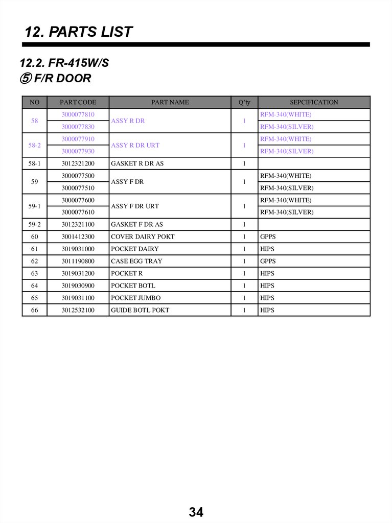
12. PARTS LIST12.2. FR-415W/S
⑤ F/R DOOR
NO
PART CODE
PART NAME
Q’ty
3000077810
58
RFM-340(WHITE)
ASSY R DR
1
3000077830
RFM-340(SILVER)
3000077910
58-2
RFM-340(WHITE)
ASSY R DR URT
1
3000077930
58-1
3012321200
RFM-340(SILVER)
GASKET R DR AS
1
ASSY F DR
1
3000077500
59
RFM-340(WHITE)
3000077510
RFM-340(SILVER)
3000077600
59-1
SEPCIFICATION
RFM-340(WHITE)
ASSY F DR URT
1
3000077610
RFM-340(SILVER)
59-2
3012321100
GASKET F DR AS
1
60
3001412300
COVER DAIRY POKT
1
GPPS
61
3019031000
POCKET DAIRY
1
HIPS
62
3011190800
CASE EGG TRAY
1
GPPS
63
3019031200
POCKET R
1
HIPS
64
3019030900
POCKET BOTL
1
HIPS
65
3019031100
POCKET JUMBO
1
HIPS
66
3012532100
GUIDE BOTL POKT
1
HIPS
34
36.
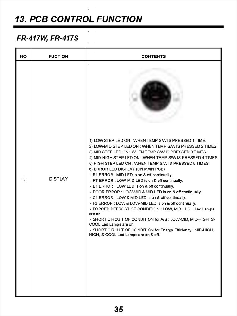
13. PCB CONTROL FUNCTIONFR-417W, FR-417S
NO
1.
FUCTION
DISPLAY
CONTENTS
1) LOW STEP LED ON : WHEN TEMP S/W IS PRESSED 1 TIME.
2) LOW-MID STEP LED ON : WHEN TEMP S/W IS PRESSED 2 TIMES.
3) MID STEP LED ON : WHEN TEMP S/W IS PRESSED 3 TIMES.
4) MID-HIGH STEP LED ON : WHEN TEMP S/W IS PRESSED 4 TIMES.
5) HIGH STEP LED ON : WHEN TEMP S/W IS PRESSED 5 TIMES.
6) ERROR LED DISPLAY (ON MAIN PCB)
- R1 ERROR : MID LED is on & off continually.
- RT ERROR : LOW-MID LED is on & off continually.
- D1 ERROR : LOW LED is on & off continually.
- DOOR ERROR : LOW-MID & MID LED is on & off continually.
- C1 ERROR : LOW & MID LED is on & off continually.
- F3 ERROR : LOW & LOW-MID LED is on & off continually.
- FORCED DEFROST OF CONDITION : LOW, MID, HIGH Led Lamps
are on.
- SHORT CIRCUIT OF CONDITION for A/S : LOW-MID, MID-HIGH, SCOOL Led Lamps are on.
- SHORT CIRCUIT OF CONDITION for Energy Efficiency : MID-HIGH,
HIGH, S-COOL Led Lamps are on & off.
35
37.
NOFUCTION
CONTENTS
1) TEMP. CONTROL SWITCH
1.1- TEMP. CONTROL
When TEMP CONTROL button is pressed, the led lamps MID,
MID-HIGH,HIGH,LOW,LOW-MID will be on in sequence.
TEMPERATURE will be set if the button doesn’t get pressed again
within 5 sec.
1.2- FORCED DEFROST : will be start when this button pushed for
over 5 seconds continuously.
1.3- SHORT CIRCUIT OPERATION : will be started and stopped when
this button pushed over 30 times.
2) TEMPERATURE CONTROL
2.1- COMP will be controlled by the on/off condition of each mode.
2.2- STEP DIFF of ROOM R : LOW/LOW-MID – 1.5 deg,
LOW-MID/MID – 1.5 deg,
MID/MID-HIGH – 2.0 deg,
MID-HIGH/HIGH – 2.0 deg
2.3- OFF point of ROOM R in MID position : 2.0°C
2.4- ON/OFF DIFF of ROOM R : 1.7°C
2.
TEMPERATURE
ADJUSTMENT
&
CONTROL
3) FORCED DEFROST
3.1- Defrost mode will be Started independent of the cycle.
3.2- The flow is same as the general defrost mode flow.
4) SHORT CIRCUIT OPERATION
4.1- COMP & FAN will be on independent of the operation condition.
4.2- The time limit of SHORT CIRCUIT OPERATION : 18 hrs
36
38.
NO3.
4.
5.
6.
7.
FUCTION
S-COOL
Determination of
DEFROST
DEFROST
MODE
INITIAL
DEFROST
PREVENTION
OF COMP
RESTART
CONTENTS
- Press S-COOL SWITCH and make S-COOL led lamp on.
- The time limit of S-COOL Mode : 40 minutes
OFF POINT : -7°C
- After reach OFF POINT, Operate “HIGH” mode until time limit.
1) Starting condition of Defrost Period
1.1- Accumulated running time of COMP : 6,8,10,12 hrs.
1.2- Running rate of COMP (per 2hrs of Accumulated running time) :
more than 80%
1.3- Accumulated running time of Door Open : 3 minutes.
1.4- Total time (COMP on time + COMP off time) : 60 hrs.
1.5- Room Temperature (RT) : more than 35°C
1.6- Errors of every kinds : R1, D1, F3, C1, RT/S, Door SW error.
2) Starting condition of Defrost Period
2.1- When satisfying the condition ‘1)’
2.2- Unless satisfying the condition ‘2.1’, when accumulated running
time of comp is 14hrs, defrost mode starts immediately.
2.3- Unless satisfying the condition ‘2.1, 2.2’, when total time (COMP on
time + COMP off time) is 60 hrs, defrost mode starts immediately.
1) General Defrost Mode
1.1- Start : By determination of defrost
1.2- Process : General operation – Heater on – Pause(4min) – General
operation – Heater defrosts: When the temperature at D-sensor is over
10°C, heater turns off – Limit time: 80 min (40 min on D Sensor
ERROR)
2) Forced Defrost Mode
2.1- Start: by press S-COOL for continuously and TEMP. CONTROL
button 5 times.
2.2- Process: same as General Defrost Mode
- Heater is supposed to be on Initial 30 seconds. (for TEST)
2.3- Display : led lamps ‘LOW-MID’, ‘MID-HIGH’, ‘S-COOL’ are on.
1) When power is on, if the temperature at the D-sensor is under 3.5°C,
then General Defrost Mode starts.
2) When initial defrost mode starts, heater will be on directly and defrost
mode will be started.
COMP. doesn’t work after COMP. turns off even though R-sensor is on
condition. (This is to protect comp.)
1) General operation : The COMP can’t be on within 6 min.
2) Operation of LOW RT : The COMP can’t be on within 30 min.
37
39.
NOFUCTION
CONTENTS
- ERROR DISPLAY
- When error happens, it is displayed on led lamp.
1) R1 ERROR (It happens when R-Sensor is OPEN or SHORT)
1.1- DISPLAY : MID LED is on & off continually.
1.2- CONTROL : Controlled by the condition of RT
(Unit : min)
RT/S TEMP
COMP. Operating TIME
(ON/OFF)
8.
9.
10.
ERROR
DISPLAY
&
CONTROL
SHORT CIRCUIT
TEST
FUNCTION
OF
TIME REDUCTION
~13°C ~19°C ~29°C 29°C~
6/34
10/30
16/24
20/20
1.3- CANCEL : when R-Sensor is working normally.
2) RT ERROR (It happens when RT-Sensor is OPEN or SHORT)
2.1- DISPLAY : LOW-MID LED is on & off continually.
2.2- CONTROL : The system is normally operating but the controlling by
RT-Sensor doesn’t work.
2.3- CANCEL : when RT-Sensor is working normally.
3) D1 ERROR (It happens when D-Sensor is OPEN or SHORT)
3.1- DISPLAY : LOW LED is on & off continually.
3.2- CONTROL : Return to next limit defrost time (80 min)
3.3- CANCEL : when D-Sensor is working normally.
4) DR ERROR
4.1- DISPLAY : LOW-MID,MID LED Lamps are on & off continually.
4.2- CONTROL : Deletion of function related door switch sensing
4.3- If door switch (open & close) is sensed, the error is terminated
automatically
5) C1 ERROR (When D-Sensor is more than -5°C, Comp operates over
3 hrs)
5.1- DISPLAY : LOW & MID LED Lamps are on & off continually.
5.2- CONTROL : The system is normally operating
5.3- CANCEL : When Comp is off, D-Sensor is less than -5°C.
6) F3 ERROR (Return to next limit defrost time (80 min))
6.1- DISPLAY : LOW & LOW-MID LED Lamps are on & off continually.
6.2- CONTROL : At Defrost Mode, Deletion of Pre-cool Mode.
6.3- CANCEL : Completion of defrost returned by D-Sensor.
1) START : by pressing TEMP CONTROL Button 30 times continuously.
2) CANCEL : the system generally operates after the limit time 18 hrs.
passes.
3) DISPLAY : LED lamps are LOW-MID, MID-HIGH, S-COOL on.
4) CONTROL : COMP & FAN will be on independent of the operating
condition. (There is no defrost mode on this test.)
1) HOW TO REDUCE
1 min : Click FAST KEY one time
30 min : If you press FAST KEY continuously, you can reduce 30
minutes on each 2.5 seconds with buzzer.
2) Practice Use : Can be applied to reduce needless time on test.
EX) function of stop for 6 min
38
40.
NO11.
FUCTION
CONTENTS
FUCTION
OF
LOW ROOM
1) Condition of LOW RT TEMP
1.1- LOW RT Period : RT SENSOR ≤ 19°C
1.2- DIFF of LOW ROOM RT : 1 deg (Hysterisys Diff)
2) Control
2.1- When Comp. is on, R-Sensor HTR is off.
When it passes 6 min after COMP is off. R-Sensor HTR is on until
COMP is on.
2.2- COMP can’t be on within 30 min after COMP is off.
2.3- Prevention time of COMP restart can change ; If satisfy ‘a’, ’b’
condition simultaneously, prevention time of COMP restart changes 6
min.
a. Accumulated running time of COMP passes 20 seconds after COMP
is off.
b. R-Sensor is more than ‘ON’ Point TEMP.
2.4- When it is not the mode of LOW ROOM TEMP or RT-Sensor is on
ERROR (open or short), R-Sensor HTR is off.
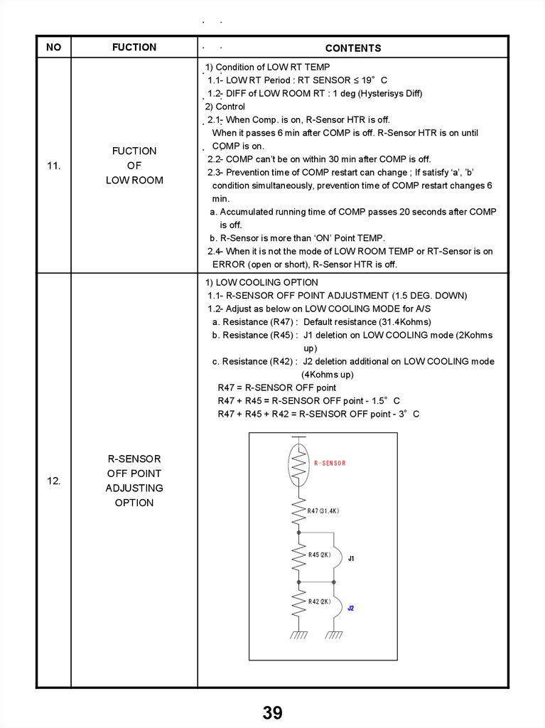
1) LOW COOLING OPTION
1.1- R-SENSOR OFF POINT ADJUSTMENT (1.5 DEG. DOWN)
1.2- Adjust as below on LOW COOLING MODE for A/S
a. Resistance (R47) : Default resistance (31.4Kohms)
b. Resistance (R45) : J1 deletion on LOW COOLING mode (2Kohms
up)
c. Resistance (R42) : J2 deletion additional on LOW COOLING mode
(4Kohms up)
R47 = R-SENSOR OFF point
R47 + R45 = R-SENSOR OFF point - 1.5°C
R47 + R45 + R42 = R-SENSOR OFF point - 3°C
12.
R-SENSOR
OFF POINT
ADJUSTING
OPTION
R -SEN SO R
R 47(31.4K )
R 45(2K )
J1
R 42(2K )
J2
39
41.
NOFUCTION
CONTENTS
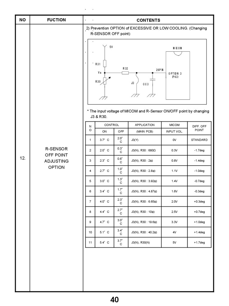
2) Prevention OPTION of EXCESSIVE OR LOW COOLING. (Changing
R-SENSOR OFF point)
5V
M IC O M
R 31
R 32
26P IN
Va
O P TIO N 3
(P 63)
R 30
J3
CC3
* The input voltage of MICOM and R-Sensor ON/OFF point by changing
J3 & R30.
N
O
12.
R-SENSOR
OFF POINT
ADJUSTING
OPTION
CONTROL
APPLICATION
MICOM
(MAIN PCB)
INPUT VOL.
ON
OFF
1
3.7°C
2.0°
C
J3(Y)
2
2.0°C
0.3°
C
3
2.3°C
4
DIFF. OFF
POINT
0V
STANDARD
J3(N), R30 : 680Ω
0.3V
-1.7deg
0.6°
C
J3(N), R30 : 2㏀
0.8V
-1.4deg
2.7°C
1.0°
C
J3(N), R30 : 2.8㏀
1.1V
-1.0deg
5
3.0°C
1.3°
C
J3(N), R30 : 3.92㏀
1.4V
-0.7deg
6
3.4°C
1.7°
C
J3(N), R30 : 4.87㏀
1.6V
-0.3deg
7
4.0°C
2.3°
C
J3(N), R30 : 6.65㏀
2.0V
+0.3deg
8
4.4°C
2.7°
C
J3(N), R30 : 10㏀
2.5V
+0.7deg
9
4.7°C
3.0°
C
J3(N), R30 : 19.6㏀
3.3V
+1.0deg
10
5.1°C
3.4°
C
J3(N), R30 : 40.2㏀
4V
+1.4deg
11
5.4°C
3.7°
C
J3(N), R30(N)
5V
+1.7deg
40
42.
NOFUCTION
CONTENTS
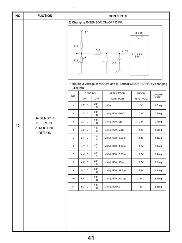
3) Changing R-SENSOR ON/OFF DIFF.
5V
M IC O M
R 25
R 28
27P IN
Va
O P TIO N 2
(P 64)
R 23
J4
CC6
* The input voltage of MICOM and R-Sensor ON/OFF DIFF. by changing
J4 & R64.
CONTROL
APPLICATION
MICOM
(MAIN PCB)
INPUT VOL.
NO
12.
R-SENSOR
OFF POINT
ADJUSTING
OPTION
ON
OFF
1
3.7°C
2.0°
C
J3(Y)
2
2.3°C
2.0°
C
3
2.7°C
4
ON/OFF
DIFF.
0V
1.7deg
J3(N), R30 : 680Ω
0.3V
0.3deg
2.0°
C
J3(N), R30 : 2㏀
0.8V
0.7deg
3.0°C
2.0°
C
J3(N), R30 : 2.8㏀
1.1V
1.0deg
5
3.4°C
2.0°
C
J3(N), R30 : 3.92㏀
1.4V
1.4deg
6
4.1°C
2.0°
C
J3(N), R30 : 4.87㏀
1.6V
2.1deg
7
4.4°C
2.0°
C
J3(N), R30 : 6.65㏀
2.0V
2.4deg
8
4.8°C
2.0°
C
J3(N), R30 : 10㏀
2.5V
2.8deg
9
5.1°C
2.0°
C
J3(N), R30 : 19.6㏀
3.3V
3.1deg
10
5.4°C
2.0°
C
J3(N), R30 : 40.2㏀
4V
3.5deg
11
5.7°C
2.0°
C
J3(N), R30(N)
5V
3.8deg
41