
 life safety
 electronics
Similar presentations:

")


M –Project Training Manual
1.
World-top 333 完成의 해Confidential
M –Project Training Manual
2005. 08. 24.
MWO Business Team
R&D Group
-1-
1
-1-
2.
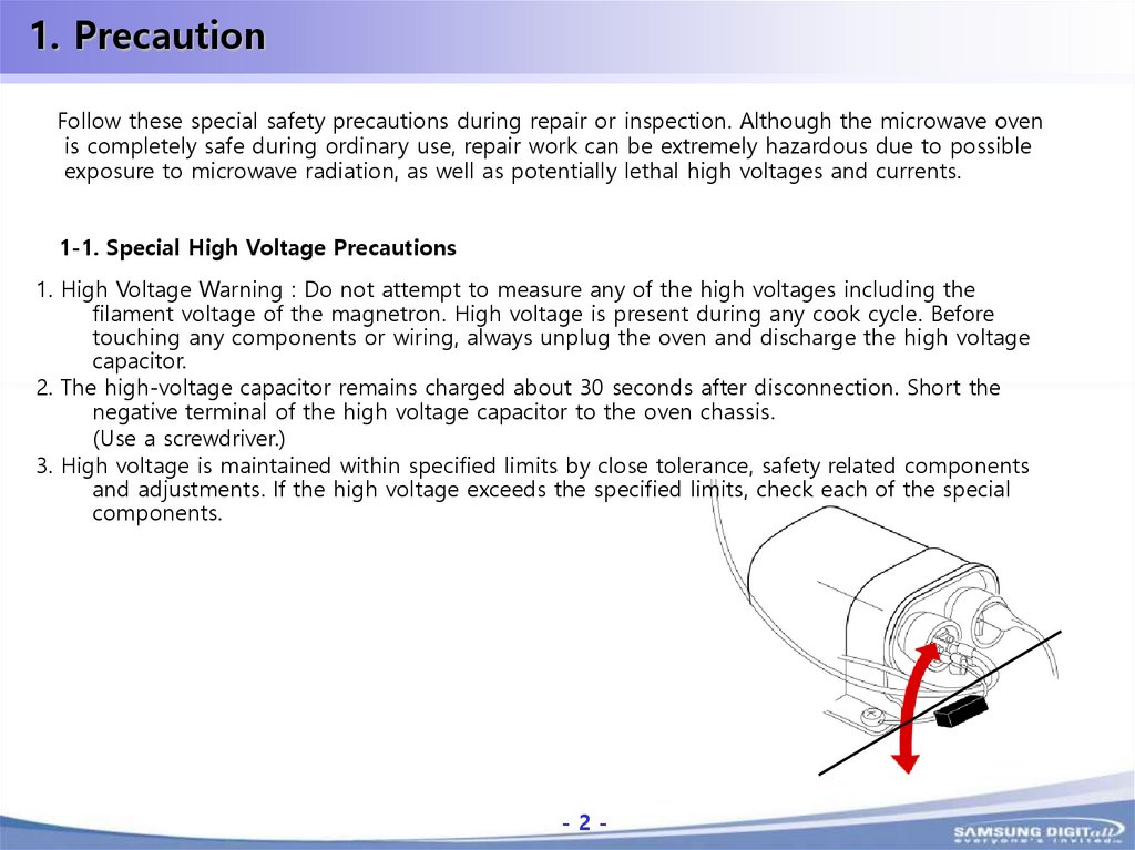
1. PrecautionFollow these special safety precautions during repair or inspection. Although the microwave oven
is completely safe during ordinary use, repair work can be extremely hazardous due to possible
exposure to microwave radiation, as well as potentially lethal high voltages and currents.
1-1. Special High Voltage Precautions
1. High Voltage Warning : Do not attempt to measure any of the high voltages including the
filament voltage of the magnetron. High voltage is present during any cook cycle. Before
touching any components or wiring, always unplug the oven and discharge the high voltage
capacitor.
2. The high-voltage capacitor remains charged about 30 seconds after disconnection. Short the
negative terminal of the high voltage capacitor to the oven chassis.
(Use a screwdriver.)
3. High voltage is maintained within specified limits by close tolerance, safety related components
and adjustments. If the high voltage exceeds the specified limits, check each of the special
components.
-2-
-2-
3.
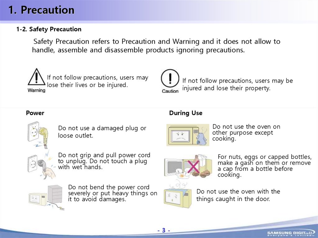
1. Precaution1-2. Safety Precaution
Safety Precaution refers to Precaution and Warning and it does not allow to
handle, assemble and disassemble products ignoring precautions.
If not follow precautions, users may
lose their lives or be injured.
If not follow precautions, users may be
injured and lose their property.
Power
During Use
Do not use the oven on
other purpose except
cooking.
Do not use a damaged plug or
loose outlet.
Do not grip and pull power cord
to unplug. Do not touch a plug
with wet hands.
For nuts, eggs or capped bottles,
make a gash on them or remove
a cap from a bottle before
cooking.
Do not bend the power cord
severely or put heavy things on
it to avoid damages.
-3-
Do not use the oven with the
things caught in the door.
-3-
4.
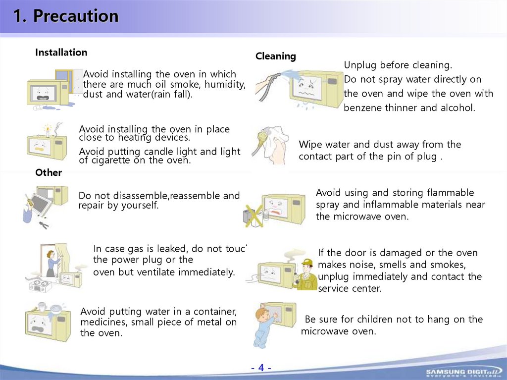
1. PrecautionInstallation
Cleaning
Avoid installing the oven in which
there are much oil smoke, humidity,
dust and water(rain fall).
Other
Avoid installing the oven in place
close to heating devices.
Avoid putting candle light and light
of cigarette on the oven.
Unplug before cleaning.
Do not spray water directly on
the oven and wipe the oven with
benzene thinner and alcohol.
Wipe water and dust away from the
contact part of the pin of plug .
Avoid using and storing flammable
spray and inflammable materials near
the microwave oven.
Do not disassemble,reassemble and
repair by yourself.
In case gas is leaked, do not touch
the power plug or the
oven but ventilate immediately.
Avoid putting water in a container,
medicines, small piece of metal on
the oven.
If the door is damaged or the oven
makes noise, smells and smokes,
unplug immediately and contact the
service center.
Be sure for children not to hang on the
microwave oven.
-4-
-4-
5.
1. Precaution1-3. Precaution before repair
1. In case the oven is operable, the leakage of electronic waves should be inspected before
service.
*If the leakage of microwave exceeds 5mW/cm2, call the service center.
2. Do not connect a power cord which does not have earth terminal.
3. Check if the cabinet is empty inside and there is a space to have a possible access to
dangerous electricity before service. (Ex: holes of lamp, ventilating holes etc.).
4. Service engineers are recommended to take off the watch while repairing MWO, and
check whether devices to prevent electric shock are properly installed and work well.
1-4. Precaution during repair
1. Do not operate the oven with the door open.
2. Make sure to earth the cavity always before testing all terminals, remove the earthed
wires last after the test.
3. Check the lead wire to be disconnected and power off always when inspecting the
connection of switches or transformers.
4. Parts should be replaced according to wiring diagram to avoid possible leakage of
microwave. Moreover, the parts such as primary and secondary interlock switches,
interlock monitor switch should be used according to specific specifications.
-5-
-5-
6.
1. Precaution1-4. Precaution during repair
5. If the fuse is blown by interlock monitor switch, replace all the following parts.
Primary switch, Door sensing switch, power relay and interlock monitor switch.
Check whether the specification of fuse is met.
6. Design Alteration Warning : Use exact replacement parts only which are specified in parts
lists and the drawings of this manual. It is very important for interlock switches described
above.
7. Do not alter or add to the electric or mechanical design in the process of repairing MWO.
Also, disconnect the power cord always before replacing all parts or reinstalling.
8. Some semiconductor(“solid state”) devices are easily damaged by static electricity.
Some components are called ESDs(ELECTROSTATICALLY SENSITIVE DEVICES).
They include the integrated circuits and field effect transistor. Make sure remove static
electricity by touching the earth generally before handing all semiconductor compartments or
assemblies.
9. To replace with parts having the same rating is more important in heat-resisting and
electrical insulation. Replacement parts have possible dangers of fire because they do not
have safety features unlike original parts against shocks, fires or other dangers.
-6-
-6-
7.
1. Precaution1-5. Precaution after repair
1. Do not connect the power cord which does not have earthed terminals.
2. Check if the cabinet is empty inside and there is a space to have a possible access to
dangerous electricity before service. (Ex: holes of lamp, ventilating holes etc.).
3. Check if the leakage of microwave exceeds 5mW/cm2 before returning the oven to customers.
4. Do not operate the oven by force with the door open.
-7-
-7-
8.
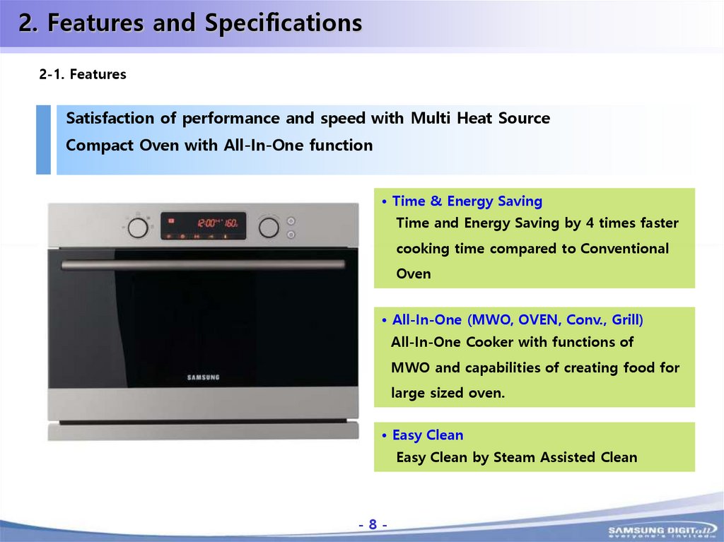
2. Features and Specifications2-1. Features
Satisfaction of performance and speed with Multi Heat Source
Compact Oven with All-In-One function
• Time & Energy Saving
Time and Energy Saving by 4 times faster
cooking time compared to Conventional
Oven
• All-In-One (MWO, OVEN, Conv., Grill)
All-In-One Cooker with functions of
MWO and capabilities of creating food for
large sized oven.
• Easy Clean
Easy Clean by Steam Assisted Clean
-8-
-8-
9.
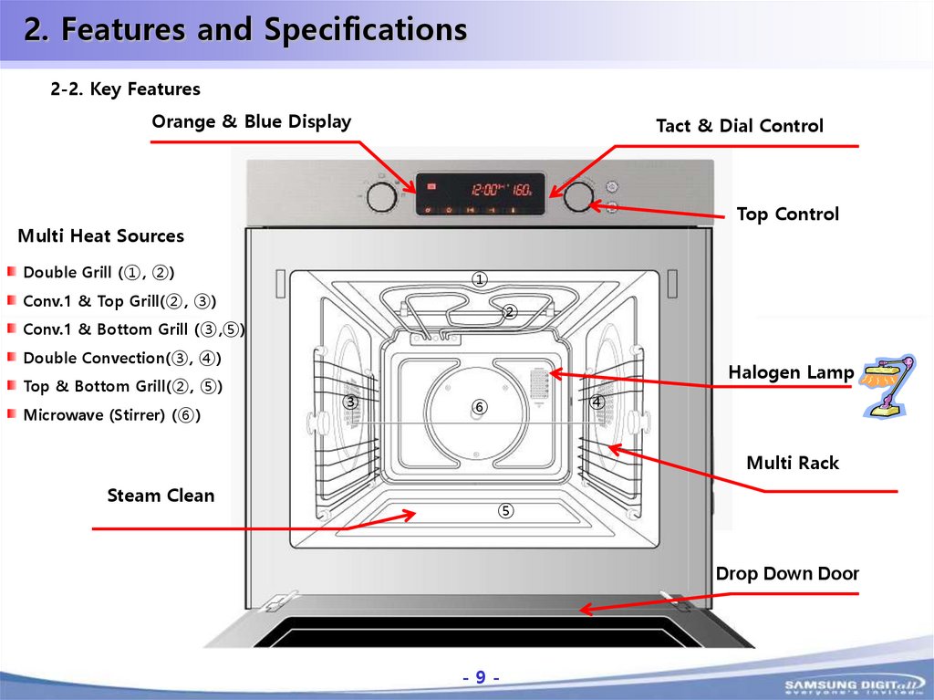
2. Features and Specifications2-2. Key Features
Orange & Blue Display
Tact & Dial Control
Top Control
Multi Heat Sources
Double Grill (①, ②)
①
Conv.1 & Top Grill(②, ③)
②
Conv.1 & Bottom Grill (③,⑤)
Double Convection(③, ④)
Top & Bottom Grill(②, ⑤)
Microwave (Stirrer) (⑥)
Halogen Lamp
③
④
⑥
Multi Rack
Steam Clean
⑤
Drop Down Door
-9-
-9-
10.
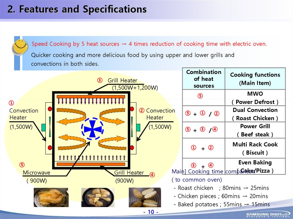
2. Features and SpecificationsSpeed Cooking by 5 heat sources → 4 times reduction of cooking time with electric oven.
Quicker cooking and more delicious food by using upper and lower grills and
convections in both sides.
Combination
of heat
sources
③ Grill Heater
(1,500W+1,200W)
①
Convection
Heater
(1,500W)
⑤
② Convection
Heater
(1,500W)
⑤ + ① /②
⑤ + ③ /④
① + ②
⑤
Microwave
( 900W)
Grill Heater ④
(900W)
- 10 -
Cooking functions
(Main Item)
MWO
( Power Defrost )
Dual Convection
( Roast Chicken )
Power Grill
( Beef steak )
Multi Rack Cook
( Biscuit )
Even Baking
③ + ④
( Cake/Pizza )
Main] Cooking time comparison
( to common oven)
- Roast chicken ; 80mins → 25mins
- Chicken pieces ; 60mins → 20mins
- Baked potatoes ; 55mins → 15mins
-10-
11.
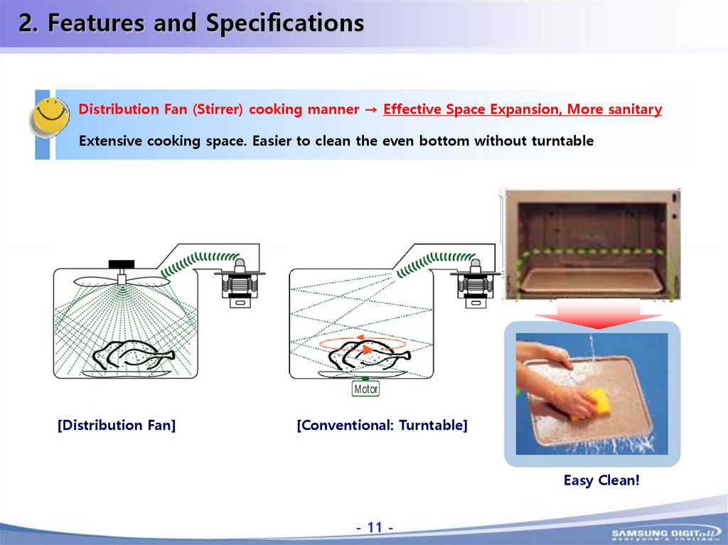
2. Features and SpecificationsDistribution Fan (Stirrer) cooking manner → Effective Space Expansion, More sanitary
Extensive cooking space. Easier to clean the even bottom without turntable
VS
[Distribution Fan]
[Conventional: Turntable]
Easy Clean!
- 11 -
-11-
12.
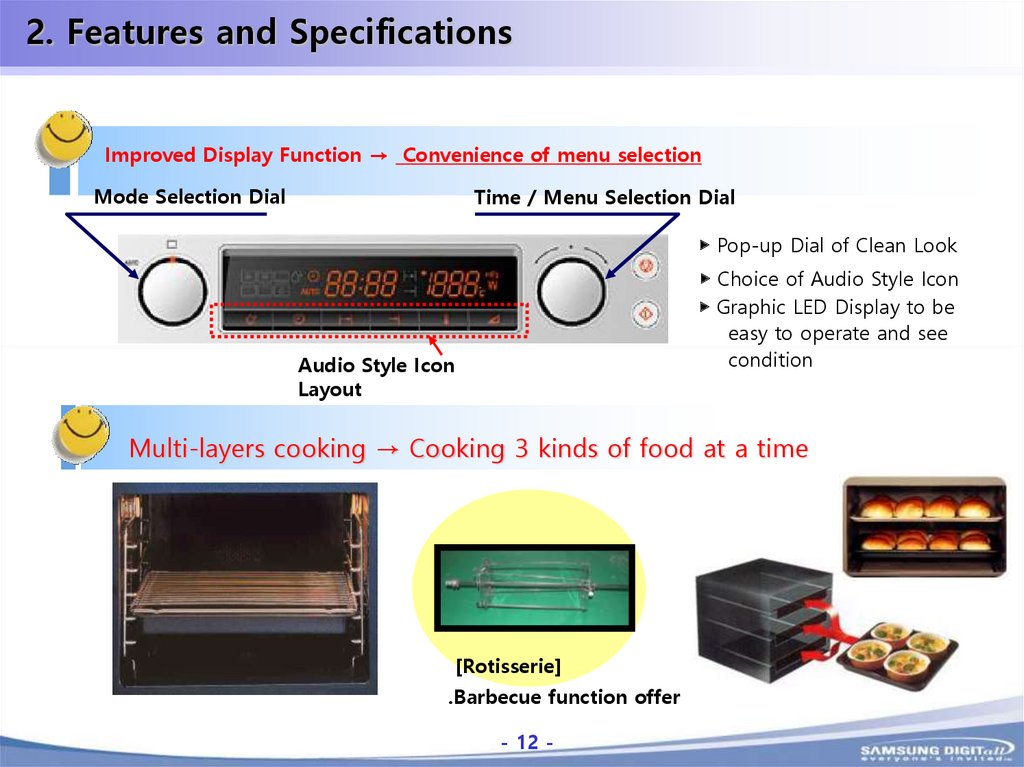
2. Features and SpecificationsImproved Display Function → Convenience of menu selection
Mode Selection Dial
Time / Menu Selection Dial
▶ Pop-up Dial of Clean Look
▶ Choice of Audio Style Icon
▶ Graphic LED Display to be
easy to operate and see
condition
Audio Style Icon
Layout
Multi-layers cooking → Cooking 3 kinds of food at a time
[Rotisserie]
.Barbecue function offer
- 12 -
-12-
13.
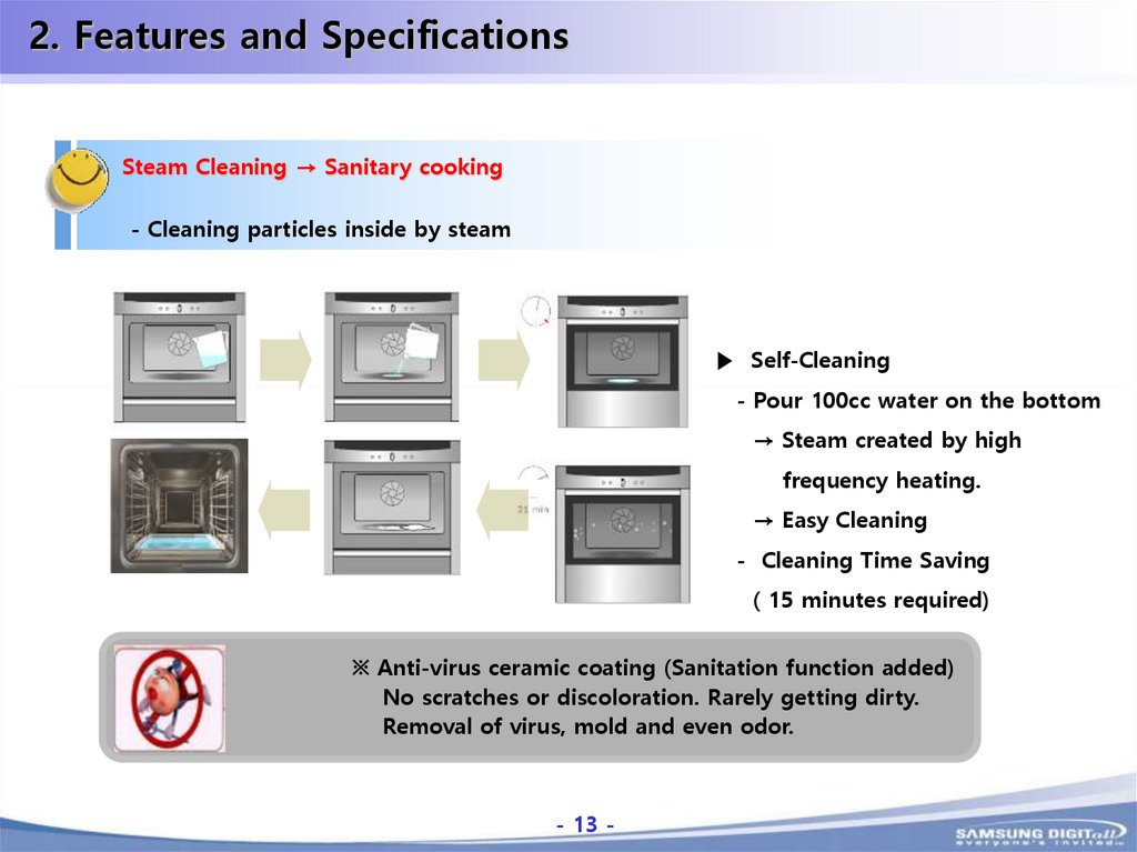
2. Features and SpecificationsSteam Cleaning → Sanitary cooking
- Cleaning particles inside by steam
▶ Self-Cleaning
- Pour 100cc water on the bottom
→ Steam created by high
frequency heating.
→ Easy Cleaning
- Cleaning Time Saving
( 15 minutes required)
※ Anti-virus ceramic coating (Sanitation function added)
No scratches or discoloration. Rarely getting dirty.
Removal of virus, mold and even odor.
- 13 -
-13-
14.
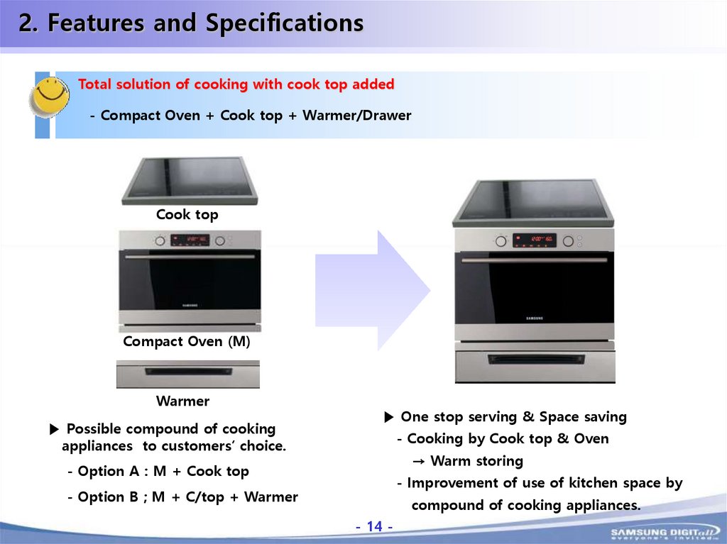
2. Features and SpecificationsTotal solution of cooking with cook top added
- Compact Oven + Cook top + Warmer/Drawer
Cook top
Compact Oven (M)
Warmer
▶ Possible compound of cooking
appliances to customers’ choice.
▶ One stop serving & Space saving
- Cooking by Cook top & Oven
→ Warm storing
- Option A : M + Cook top
- Improvement of use of kitchen space by
- Option B ; M + C/top + Warmer
compound of cooking appliances.
- 14 -
-14-
15.
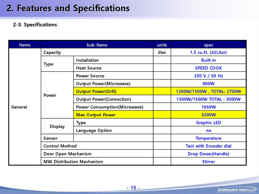
2. Features and Specifications2-3. Specifications
Items
Sub-items
Capacity
Type
General
Display
spec
liter
1.5 cu.ft. (42Liter)
Installation
Built-in
Heat Source
SPEED COOK
Power Source
230 V / 50 Hz
Output Power(Microwave)
Power
units
900W
Output Power(Grill)
1200W/1500W , TOTAL: 2700W
Output Power(Convection)
1500W/1500W TOTAL : 3000W
Power Consumption(Microwave)
1650W
Max Output Power
3200W
Type
Graphic LED
Language Option
no
Sensor
Temperature
Control Method
Tact with Encoder dial
Door Open Mechanism
Drop Down(Handle)
MW Distribution Mechanism
Stirrer
- 15 -
-15-
16.
2. Features and SpecificationsItems
Sub-items
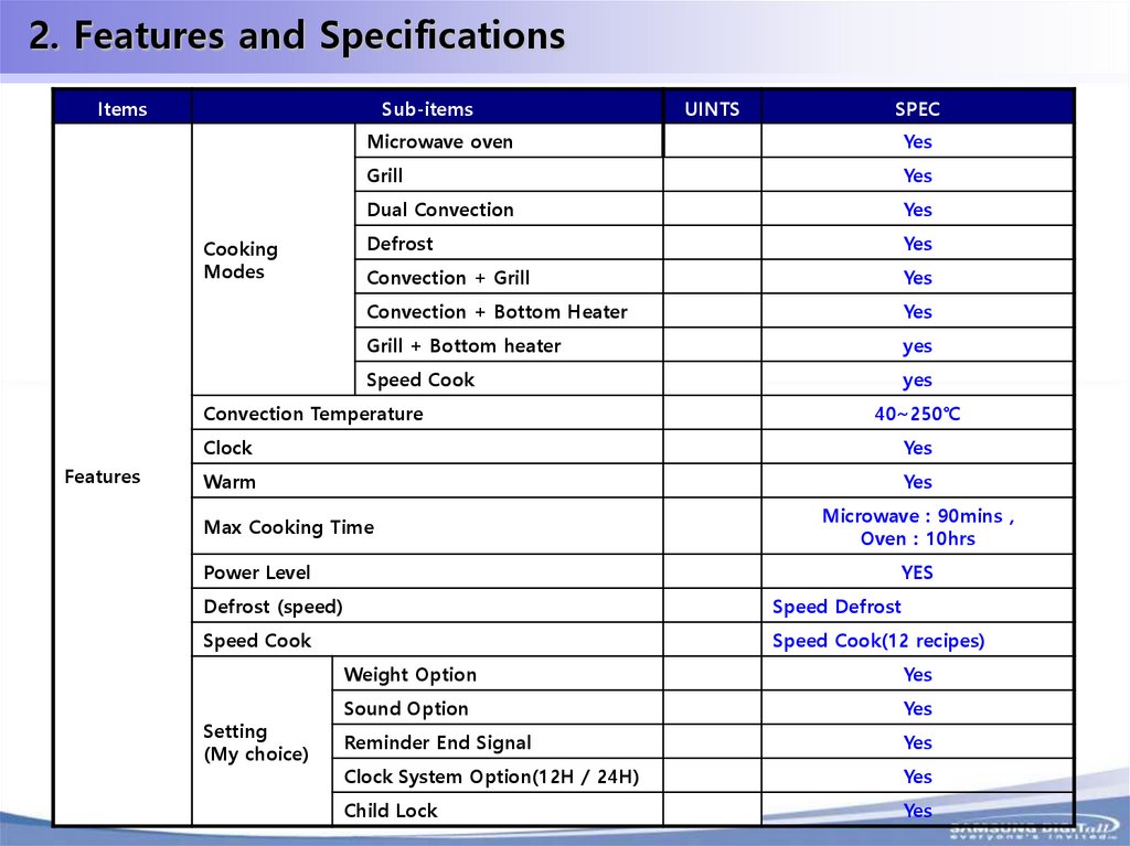
Cooking
Modes
UINTS
Microwave oven
Yes
Grill
Yes
Dual Convection
Yes
Defrost
Yes
Convection + Grill
Yes
Convection + Bottom Heater
Yes
Grill + Bottom heater
yes
Speed Cook
yes
Convection Temperature
Features
SPEC
40~250℃
Clock
Yes
Warm
Yes
Microwave : 90mins ,
Oven : 10hrs
Max Cooking Time
Power Level
YES
Defrost (speed)
Speed Defrost
Speed Cook
Speed Cook(12 recipes)
Setting
(My choice)
Weight Option
Yes
Sound Option
Yes
Reminder End Signal
Yes
Clock System Option(12H / 24H)
Yes
Child Lock
Yes
- 16 -
-16-
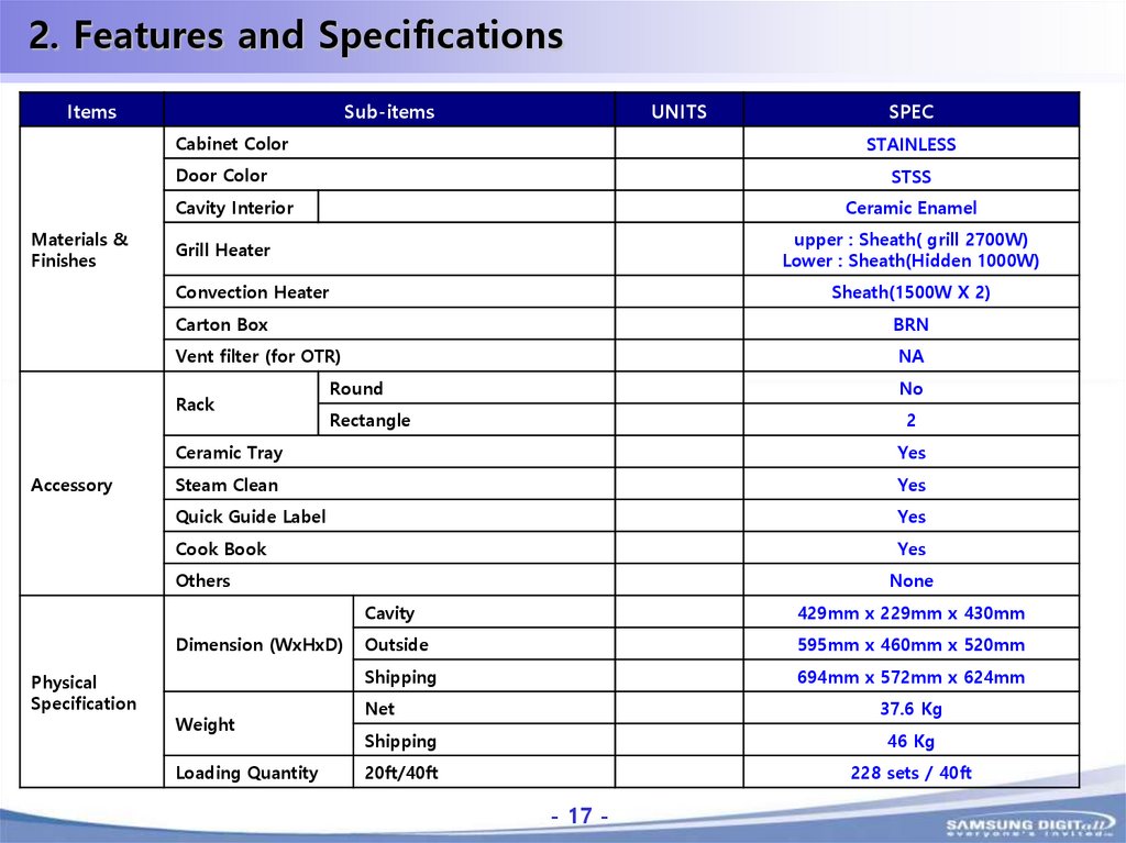
17.
2. Features and SpecificationsItems
Sub-items
UNITS
Cabinet Color
STAINLESS
Door Color
STSS
Cavity Interior
Materials &
Finishes
Ceramic Enamel
upper : Sheath( grill 2700W)
Lower : Sheath(Hidden 1000W)
Grill Heater
Convection Heater
Sheath(1500W X 2)
Carton Box
BRN
Vent filter (for OTR)
NA
Rack
Accessory
Round
No
Rectangle
2
Ceramic Tray
Yes
Steam Clean
Yes
Quick Guide Label
Yes
Cook Book
Yes
Others
Dimension (WxHxD)
Physical
Specification
SPEC
Weight
Loading Quantity
None
Cavity
429mm x 229mm x 430mm
Outside
595mm x 460mm x 520mm
Shipping
694mm x 572mm x 624mm
Net
37.6 Kg
Shipping
46 Kg
20ft/40ft
228 sets / 40ft
- 17 -
-17-
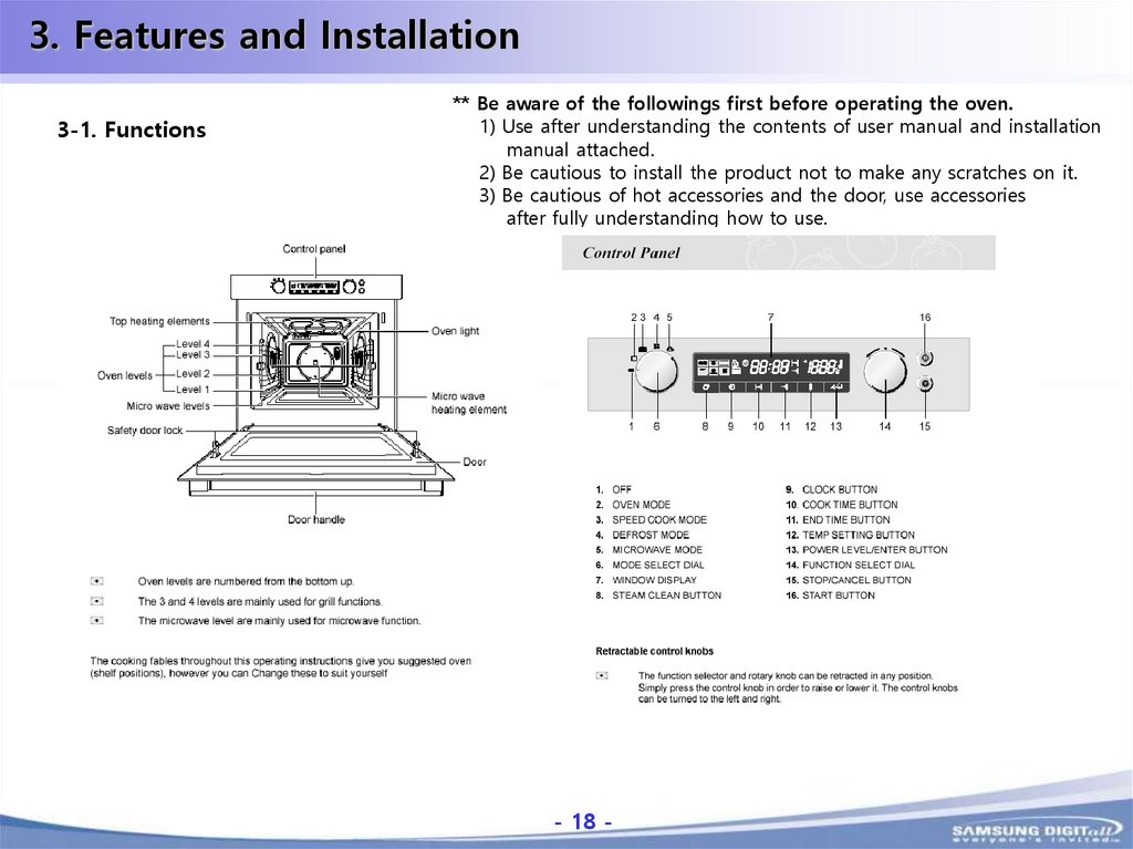
18.
3. Features and Installation3-1. Functions
** Be aware of the followings first before operating the oven.
1) Use after understanding the contents of user manual and installation
manual attached.
2) Be cautious to install the product not to make any scratches on it.
3) Be cautious of hot accessories and the door, use accessories
after fully understanding how to use.
- 18 -
-18-
19.
3. Features and Installation3-2. How to install the oven
* Click the icon below to see how to install the oven.
- 19 -
-19-
20.
4. Disassembly and Reassembly4-1. Preparations
Basically, the followings are required to disassemble and reassemble the oven.
1. Electric driver(Use Plus driver if there is not an electric driver) 2. 8mm vox driver
3. Star driver 4. Jig for assembly and disassembly of door provided by Samsung.
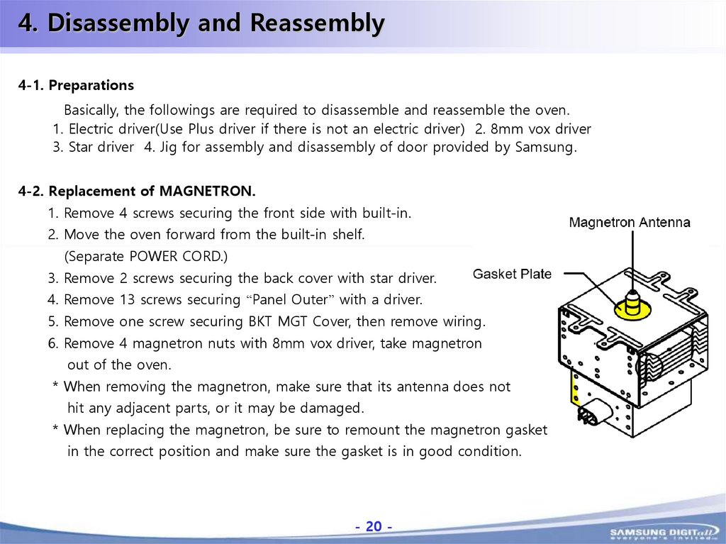
4-2. Replacement of MAGNETRON.
1. Remove 4 screws securing the front side with built-in.
2. Move the oven forward from the built-in shelf.
(Separate POWER CORD.)
3. Remove 2 screws securing the back cover with star driver.
4. Remove 13 screws securing “Panel Outer” with a driver.
5. Remove one screw securing BKT MGT Cover, then remove wiring.
6. Remove 4 magnetron nuts with 8mm vox driver, take magnetron
out of the oven.
* When removing the magnetron, make sure that its antenna does not
hit any adjacent parts, or it may be damaged.
* When replacing the magnetron, be sure to remount the magnetron gasket
in the correct position and make sure the gasket is in good condition.
- 20 -
-20-
21.
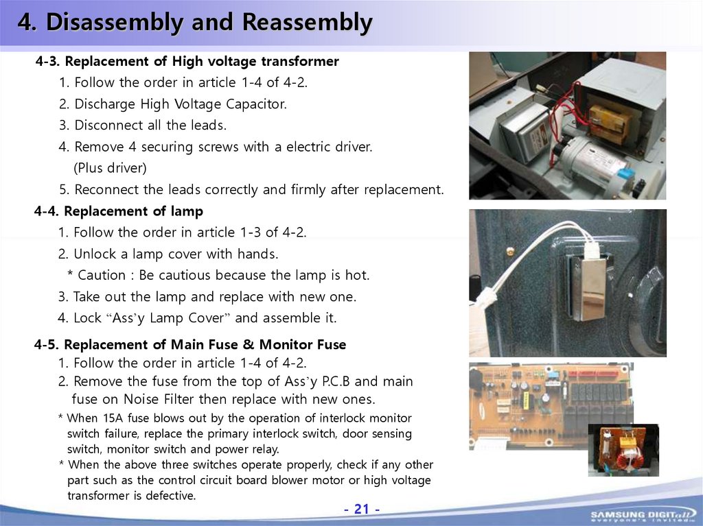
4. Disassembly and Reassembly4-3. Replacement of High voltage transformer
1. Follow the order in article 1-4 of 4-2.
2. Discharge High Voltage Capacitor.
3. Disconnect all the leads.
4. Remove 4 securing screws with a electric driver.
(Plus driver)
5. Reconnect the leads correctly and firmly after replacement.
4-4. Replacement of lamp
1. Follow the order in article 1-3 of 4-2.
2. Unlock a lamp cover with hands.
* Caution : Be cautious because the lamp is hot.
3. Take out the lamp and replace with new one.
4. Lock “Ass’y Lamp Cover” and assemble it.
4-5. Replacement of Main Fuse & Monitor Fuse
1. Follow the order in article 1-4 of 4-2.
2. Remove the fuse from the top of Ass’y P.C.B and main
fuse on Noise Filter then replace with new ones.
* When 15A fuse blows out by the operation of interlock monitor
switch failure, replace the primary interlock switch, door sensing
switch, monitor switch and power relay.
* When the above three switches operate properly, check if any other
part such as the control circuit board blower motor or high voltage
transformer is defective.
- 21 -
-21-
22.
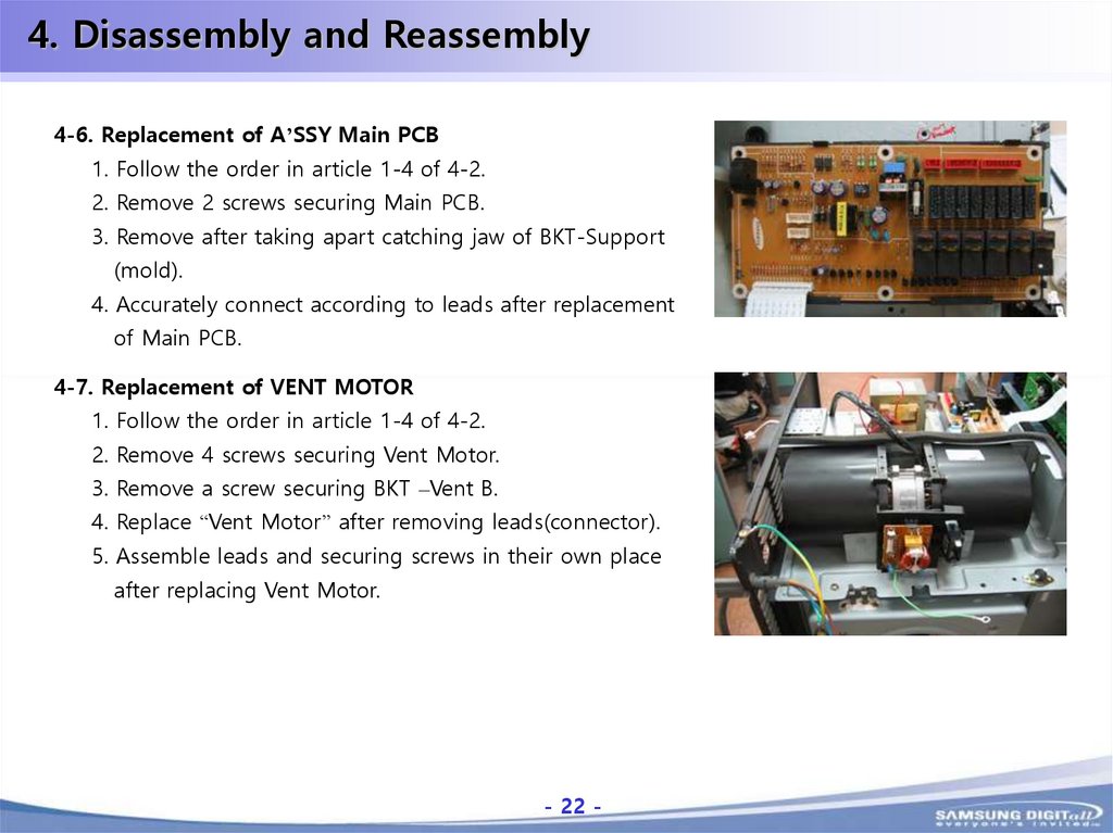
4. Disassembly and Reassembly4-6. Replacement of A’SSY Main PCB
1. Follow the order in article 1-4 of 4-2.
2. Remove 2 screws securing Main PCB.
3. Remove after taking apart catching jaw of BKT-Support
(mold).
4. Accurately connect according to leads after replacement
of Main PCB.
4-7. Replacement of VENT MOTOR
1. Follow the order in article 1-4 of 4-2.
2. Remove 4 screws securing Vent Motor.
3. Remove a screw securing BKT –Vent B.
4. Replace “Vent Motor” after removing leads(connector).
5. Assemble leads and securing screws in their own place
after replacing Vent Motor.
- 22 -
-22-
23.
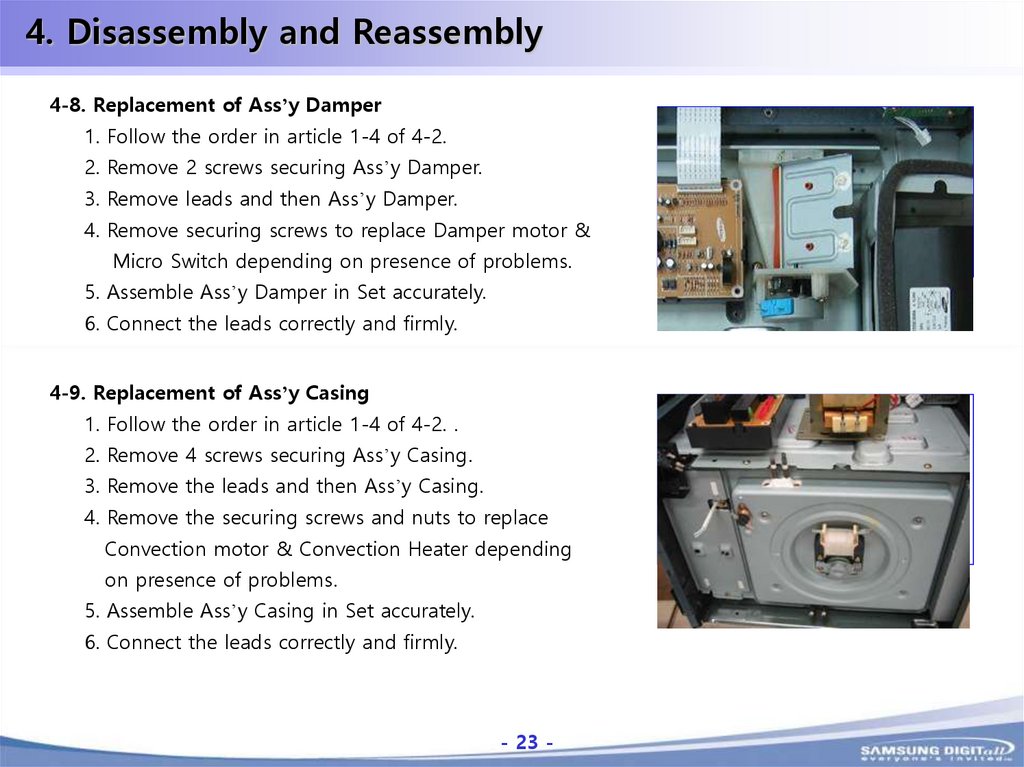
4. Disassembly and Reassembly4-8. Replacement of Ass’y Damper
1. Follow the order in article 1-4 of 4-2.
2. Remove 2 screws securing Ass’y Damper.
그림삽입
3. Remove leads and then Ass’y Damper.
4. Remove securing screws to replace Damper motor &
Micro Switch depending on presence of problems.
5. Assemble Ass’y Damper in Set accurately.
6. Connect the leads correctly and firmly.
4-9. Replacement of Ass’y Casing
1. Follow the order in article 1-4 of 4-2. .
2. Remove 4 screws securing Ass’y Casing.
그림삽입
3. Remove the leads and then Ass’y Casing.
4. Remove the securing screws and nuts to replace
Convection motor & Convection Heater depending
on presence of problems.
5. Assemble Ass’y Casing in Set accurately.
6. Connect the leads correctly and firmly.
- 23 -
-23-
24.
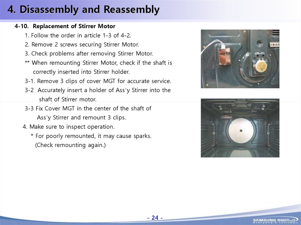
4. Disassembly and Reassembly4-10. Replacement of Stirrer Motor
1. Follow the order in article 1-3 of 4-2.
2. Remove 2 screws securing Stirrer Motor.
3. Check problems after removing Stirrer Motor.
** When remounting Stirrer Motor, check if the shaft is
correctly inserted into Stirrer holder.
3-1. Remove 3 clips of cover MGT for accurate service.
3-2 Accurately insert a holder of Ass’y Stirrer into the
shaft of Stirrer motor.
3-3 Fix Cover MGT in the center of the shaft of
Ass’y Stirrer and remount 3 clips.
4. Make sure to inspect operation.
* For poorly remounted, it may cause sparks.
(Check remounting again.)
- 24 -
-24-
25.
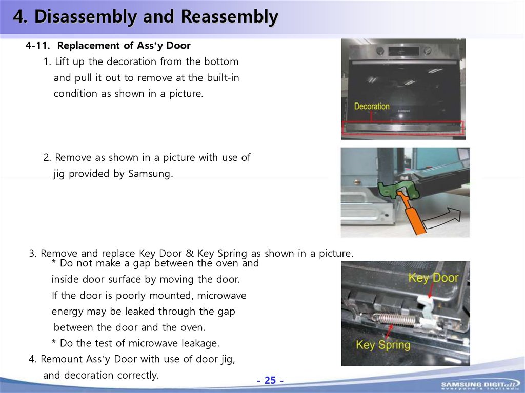
4. Disassembly and Reassembly4-11. Replacement of Ass’y Door
1. Lift up the decoration from the bottom
and pull it out to remove at the built-in
condition as shown in a picture.
2. Remove as shown in a picture with use of
jig provided by Samsung.
3. Remove and replace Key Door & Key Spring as shown in a picture.
* Do not make a gap between the oven and
inside door surface by moving the door.
If the door is poorly mounted, microwave
energy may be leaked through the gap
between the door and the oven.
* Do the test of microwave leakage.
4. Remount Ass’y Door with use of door jig,
and decoration correctly.
- 25 -
-25-
26.
5. Alignment and AdjustmentsPrecaution
1. High voltage is present at the high voltage terminals during any cook cycle.
2. It is neither necessary nor advisable to attempt measurement of the high voltage.
3. Before touching any oven components or wiring, always unplug the oven from its power
source and discharge the high voltage capacitor.
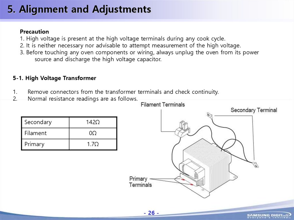
5-1. High Voltage Transformer
1.
2.
Remove connectors from the transformer terminals and check continuity.
Normal resistance readings are as follows.
Secondary
142Ω
Filament
0Ω
Primary
1.7Ω
- 26 -
-26-
27.
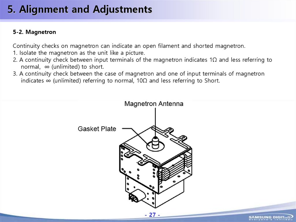
5. Alignment and Adjustments5-2. Magnetron
Continuity checks on magnetron can indicate an open filament and shorted magnetron.
1. Isolate the magnetron as the unit like a picture.
2. A continuity check between input terminals of the magnetron indicates 1Ω and less referring to
normal, ∞ (unlimited) to short.
3. A continuity check between the case of magnetron and one of input terminals of magnetron
indicates ∞ (unlimited) referring to normal, 10Ω and less referring to Short.
- 27 -
-27-
28.
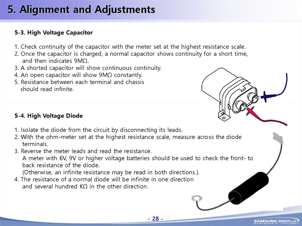
5. Alignment and Adjustments5-3. High Voltage Capacitor
1. Check continuity of the capacitor with the meter set at the highest resistance scale.
2. Once the capacitor is charged, a normal capacitor shows continuity for a short time,
and then indicates 9MΩ.
3. A shorted capacitor will show continuous continuity.
4. An open capacitor will show 9MΩ constantly.
5. Resistance between each terminal and chassis
should read infinite.
5-4. High Voltage Diode
1. Isolate the diode from the circuit by disconnecting its leads.
2. With the ohm-meter set at the highest resistance scale, measure across the diode
terminals.
3. Reverse the meter leads and read the resistance.
A meter with 6V, 9V or higher voltage batteries should be used to check the front- to
back resistance of the diode.
(Otherwise, an infinite resistance may be read in both directions.).
4. The resistance of a normal diode will be infinite in one direction
and several hundred KΩ in the other direction.
- 28 -
-28-
29.
5. Alignment and Adjustments5-5. Main relay and power control relay
The relays are located on the PCB ass’y. Isolate them from the main circuit by disconnecting
the leads. Operate the microwave oven with a water load in the oven. Set the power level to
high. Check continuity between terminals of the relays after the start pad is pressed.
5-6. Adjustment of Primary switch, Door sensing switch and monitor switch
Precaution
For continued protection against radiation hazard, replace parts in accordance with the wiring
diagram and be sure to use the correct part number for the following switches : Primary and
secondary interlock switches, and the interlock monitor switch (Replace all together). Then
follow the adjustment procedures below. After repair and adjustment, be sure to check the
continuity of all interlock switches and the interlock monitor switch.
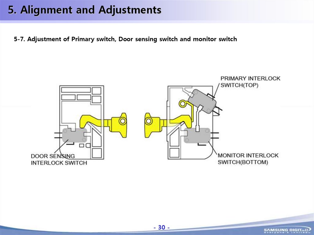
1.When mounting primary switch and interlock monitor switch to Latch body, consult the figure.
2.No specific adjustment during installation of primary switch and monitor switch to the latch
body is necessary.
3.When mounting the Latch Body to the oven assembly, adjust the Latch Body by moving it so
that the oven door will not have any play in it. Check for play in the door by pulling the door
assembly. Make sure that the latch keys move smoothly after adjustment is completed.
Completely tighten the screws holding the Latch Body to the oven assembly.
4.Reconnect to Monitor switch and check the continuity of the monitor circuit and all latch
switches again by following the components test procedures.
5.Confirm that the gap between the switch housing and the switch actuator is no more than
0.5mm when door is closed.
6.Interlock switch replacement – When replacing faulty switches, be sure switch mounting tabs
are not bent, broken or otherwise deficient in their ability to secure the switches in place.
- 29 -
-29-
30.
5. Alignment and Adjustments5-7. Adjustment of Primary switch, Door sensing switch and monitor switch
- 30 -
-30-
31.
5. Alignment and AdjustmentsCaution
Personnel should not allow exposure to microwave radiation from microwave generator or
other parts conducting microwave energy.
The output power of the magnetron can be measured by performing a water temperature rise test.
Equipment needed:
•Two 1 liter cylindrical borosilicate glass vessel (Outside diameter 190 mm)
•One glass thermometer with mercury column
NOTE: check line voltage under lead.
Low voltage will lower the magnetron output.
Make all temperature and time tests with accurate equipment.
1. Fill the one liter glass vessel with water.
2. Stir water in glass vessel with thermometer, and record glass vessel’s temperature(“T1”,10±1°C).
3. After moving the water into another glass vessel, place it in the center of the cooking tray.
Set the oven to high power and operate for 52 seconds exactly.
(3 seconds included as a holding time of magnetron.)
4. When heating is finished, stir the water again with the thermometer and measure the temperature.
2 ”).
5. Subtract T1 from T2. This will give you the water temperature rise(∆T).
- 31 -
(“T
-31-
32.
5. Alignment and Adjustments5-8. Magnetron output measurement
The output power of the magnetron can be measured by performing a
Caution
water temperature rise test.
Personnel should not allow
Equipment needed:
exposure to microwave
•Two 1 liter cylindrical borosilicate glass vessel
radiation from microwave
(Outside diameter 190 mm)
generator or other parts
•One glass thermometer with mercury column
conducting microwave
NOTE: Check line voltage under lead.
energy.
Low voltage will lower the magnetron output.
Make all temperature and time tests with accurate equipment.
1. Fill the one liter glass vessel with water.
2. Stir water in glass vessel with thermometer, and record glass vessel’s temperature(“T1”,10±1°C).
3. After moving the water into another glass vessel, place it in the center of the cooking tray.
Set the oven to high power and operate for 52 seconds exactly.
(3 seconds included as a holding time of magnetron.)
4. When heating is finished, stir the water again with the thermometer and measure the
temperature. (“T2 ”).
52 : Heating time(sec)
5. Subtract T1 from T2. This will give you the water temperature
49 : Counting time(sec)
rise(∆T).
4.187 : Coefficient for water
6. The output power is obtained by the following formula.
1000 : Water(cc)
4.187 x 1000 x ∆T + 0.55 x Mc x (T2 -T1)
∆T : Temperature rise (T2 –T1)
Output power =
Yo : Room temperature
49
Mc : Cylindrical borosilicate glass
weight
7. Normal temperature rise for this model is 9°C ~11°C at HIGH.
NOTE 1: Variations or errors in the test procedure will cause a variance in the temperature rise.
Additional power test should be made if temperature rise is marginal..
NOTE 2: Output power in W(watts) is computed by multiplying the temperature rise (step 5) by
a factor of 91 times of centigrade temperature.
- 32 -
-32-
33.
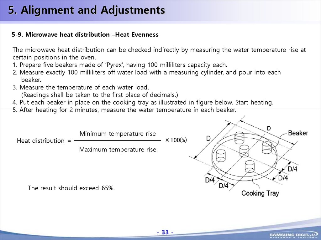
5. Alignment and Adjustments5-9. Microwave heat distribution –Heat Evenness
The microwave heat distribution can be checked indirectly by measuring the water temperature rise at
certain positions in the oven.
1. Prepare five beakers made of ‘Pyrex’, having 100 milliliters capacity each.
2. Measure exactly 100 milliliters off water load with a measuring cylinder, and pour into each
beaker.
3. Measure the temperature of each water load.
(Readings shall be taken to the first place of decimals.)
4. Put each beaker in place on the cooking tray as illustrated in figure below. Start heating.
5. After heating for 2 minutes, measure the water temperature in each beaker.
Heat distribution =
Minimum temperature rise
×100(%)
Maximum temperature rise
The result should exceed 65%.
- 33 -
-33-
34.
5. Alignment and Adjustments5-10. Procedure for measurement of microwave energy leakage
1. Pour 275±15cc of 20±5°C(68±9°F) water in a beaker which is graduated to 600cc,
and place the beaker in the center of the oven.
2.Start to operate the oven and measure the leakage by using a microwave energy survey meter.
3.Set survey meter with dual ranges to 2,450MHz.
4.When measuring the leakage, always use the 2 inch spacer cone with the probe.
Hold the probe perpendicular to the cabinet door.
Place the spacer cone of the probe on the door and/or cabinet door seam and move along the
seam. The door viewing window and the exhaust openings moving the probe in a clockwise
direction at a rate of 1 inch/sec.
If the leakage testing of the cabinet door seam is taken near a corner of the door, keep the probe
perpendicular to the areas making sure that the probe end at the base of the cone does not get
closer than 5 cm to any metal. If if gets closer than 5 cm, erroneous readings may result.
5. Measured leakage must be less than 4mW/cm2 after repair and adjustment.
Maximum allowable leakage is 5mW/cm2.
4mW/cm2 is used to allow for measurement and meter accuracy.
- 34 -
-34-
35.
5. Alignment and Adjustments5-10. Procedure for measurement of microwave energy leakage
1.Do not exceed the limited scale.
2. The test probe must be held on the grip of the handle, otherwise a false reading may result
when the operator’s hand is between the handle and the probe.
3.When high leakage is suspected, do not move the prove horizontally along the oven surface ;
this may cause damage to the probe.
4. Follow the recommendation of the manufacturer of the microwave energy survey meter.
After measuring microwave leakage
1. After adjustment and repair of a radiation preventing device, make a repair record for the
measured values, and keep the data.
2. If the radiation leakage is more than 4mW/cm2 after determining that all parts are in good
condition, functioning properly and the identical parts are replaced as listed in this manual notify
that fact to Central Service Center.
- 35 -
-35-
36.
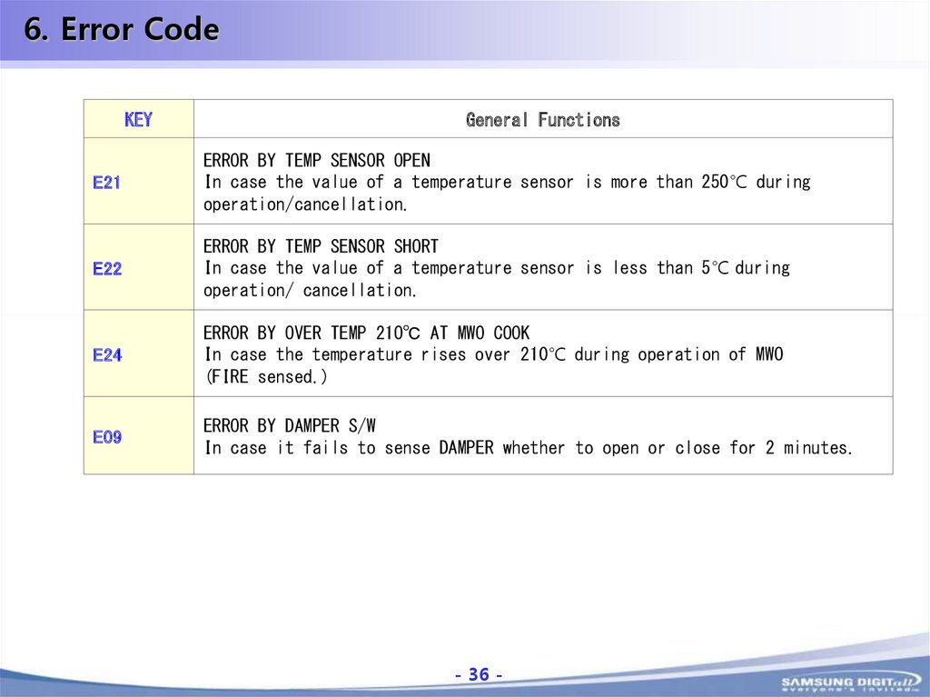
6. Error CodeKEY
General Functions
E21
ERROR BY TEMP SENSOR OPEN
In case the value of a temperature sensor is more than 250℃ during
operation/cancellation.
E22
ERROR BY TEMP SENSOR SHORT
In case the value of a temperature sensor is less than 5℃ during
operation/ cancellation.
E24
ERROR BY OVER TEMP 21O℃ AT MWO COOK
In case the temperature rises over 210℃ during operation of MWO
(FIRE sensed.)
E09
ERROR BY DAMPER S/W
In case it fails to sense DAMPER whether to open or close for 2 minutes.
- 36 -
-36-
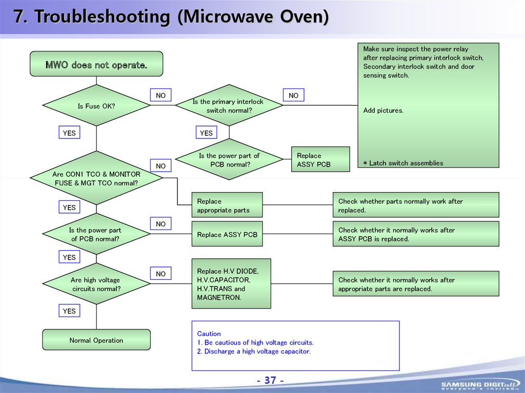
37.
7. Troubleshooting (Microwave Oven)Make sure inspect the power relay
after replacing primary interlock switch,
Secondary interlock switch and door
sensing switch.
MWO does not operate.
NO
Is Fuse OK?
YES
Is the primary interlock
switch normal?
NO
Add pictures.
YES
NO
Is the power part of
PCB normal?
Replace
ASSY PCB
* Latch switch assemblies
Are CON1 TCO & MONITOR
FUSE & MGT TCO normal?
YES
Is the power part
of PCB normal?
Replace
appropriate parts
Check whether parts normally work after
replaced.
Replace ASSY PCB
Check whether it normally works after
ASSY PCB is replaced.
Replace H.V DIODE,
H.V.CAPACITOR,
H.V.TRANS and
MAGNETRON.
Check whether it normally works after
appropriate parts are replaced.
NO
YES
Are high voltage
circuits normal?
NO
YES
Normal Operation
Caution
1. Be cautious of high voltage circuits.
2. Discharge a high voltage capacitor.
- 37 -
-37-
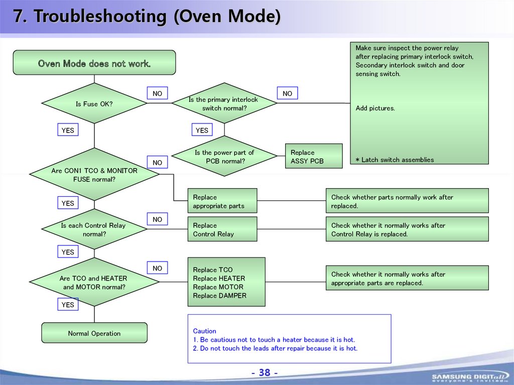
38.
7. Troubleshooting (Oven Mode)Make sure inspect the power relay
after replacing primary interlock switch,
Secondary interlock switch and door
sensing switch.
Oven Mode does not work.
NO
Is Fuse OK?
YES
Is the primary interlock
switch normal?
NO
Add pictures.
YES
NO
Is the power part of
PCB normal?
Replace
ASSY PCB
* Latch switch assemblies
Are CON1 TCO & MONITOR
FUSE normal?
YES
Is each Control Relay
normal?
NO
Replace
appropriate parts
Check whether parts normally work after
replaced.
Replace
Control Relay
Check whether it normally works after
Control Relay is replaced.
YES
NO
Are TCO and HEATER
and MOTOR normal?
Replace TCO
Replace HEATER
Replace MOTOR
Replace DAMPER
Check whether it normally works after
appropriate parts are replaced.
YES
Normal Operation
Caution
1. Be cautious not to touch a heater because it is hot.
2. Do not touch the leads after repair because it is hot.
- 38 -
-38-
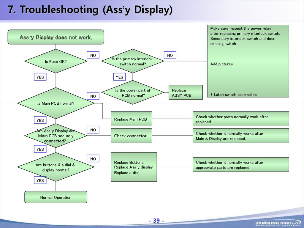
39.
7. Troubleshooting (Ass’y Display)Make sure inspect the power relay
after replacing primary interlock switch,
Secondary interlock switch and door
sensing switch.
Ass’y Display does not work.
NO
Is Fuse OK?
YES
Is the primary interlock
switch normal?
NO
Add pictures.
YES
NO
Is the power part of
PCB normal?
Replace
ASSY PCB
* Latch switch assemblies
Is Main PCB normal?
YES
Are Ass’y Display and
Main PCB securely
connected?
Replace Main PCB
Check whether parts normally work after
replaced.
Check connector
Check whether it normally works after
Main & Display are replaced.
Replace Buttons
Replace Ass’y display
Replace a dial
Check whether it normally works after
appropriate parts are replaced.
NO
YES
NO
Are buttons & a dial &
display normal?
YES
Normal Operation
- 39 -
-39-
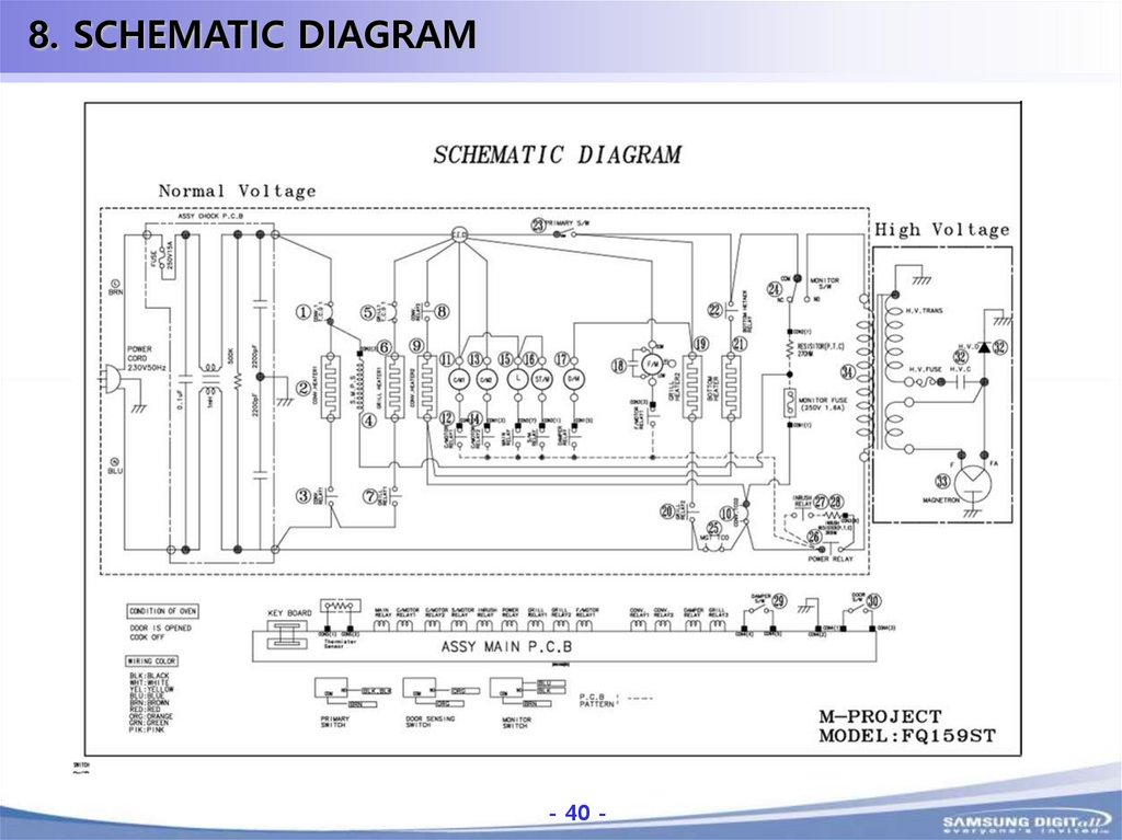
40.
8. SCHEMATIC DIAGRAM- 40 -
-40-
41.
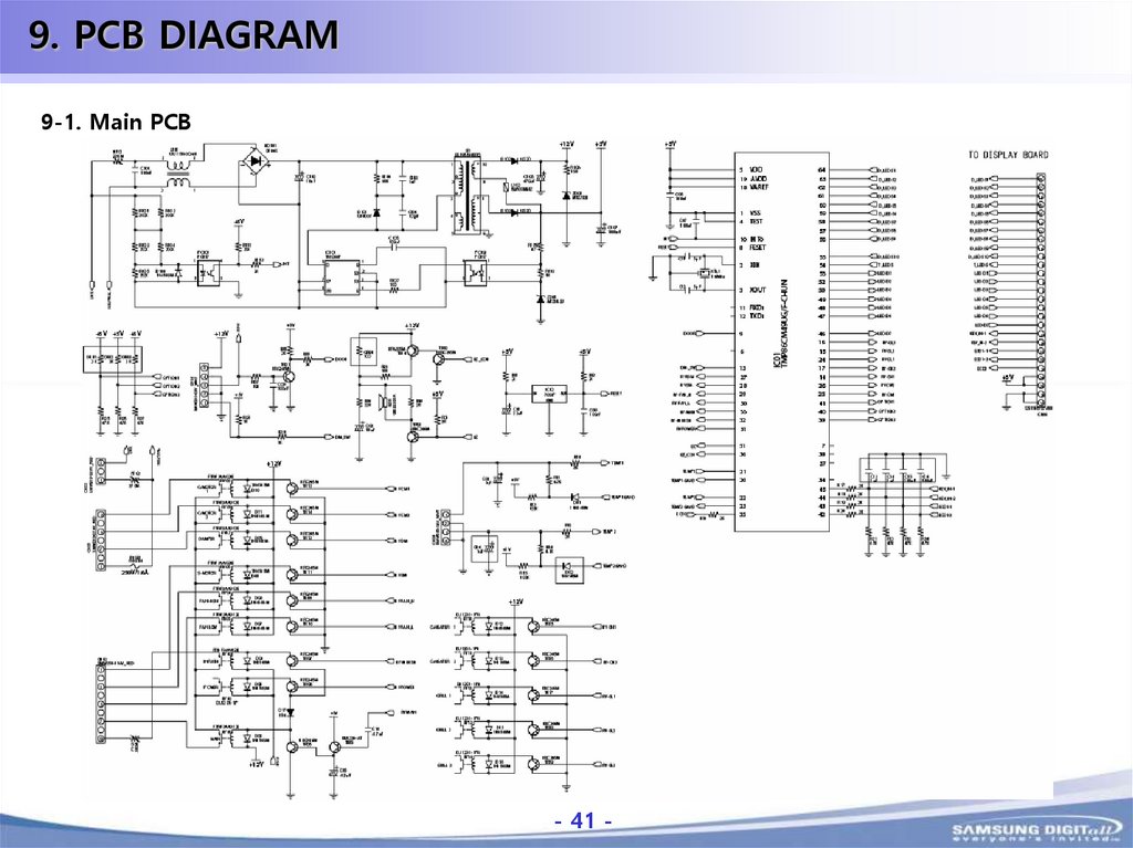
9. PCB DIAGRAM9-1. Main PCB
- 41 -
-41-
42.
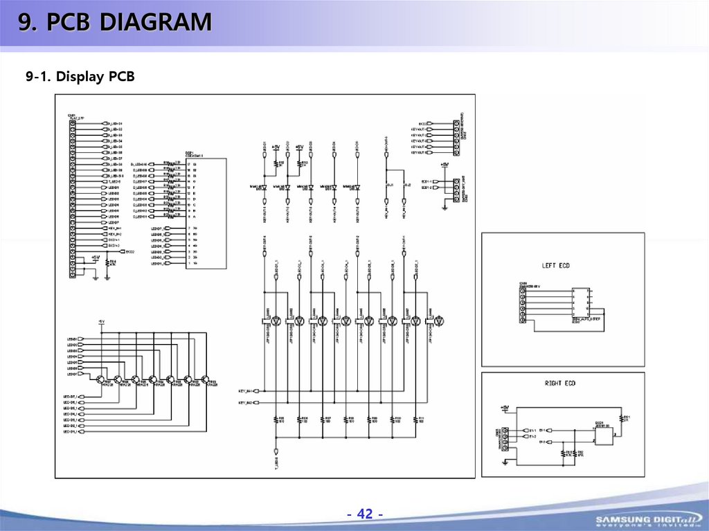
9. PCB DIAGRAM9-1. Display PCB
- 42 -
-42-
43.
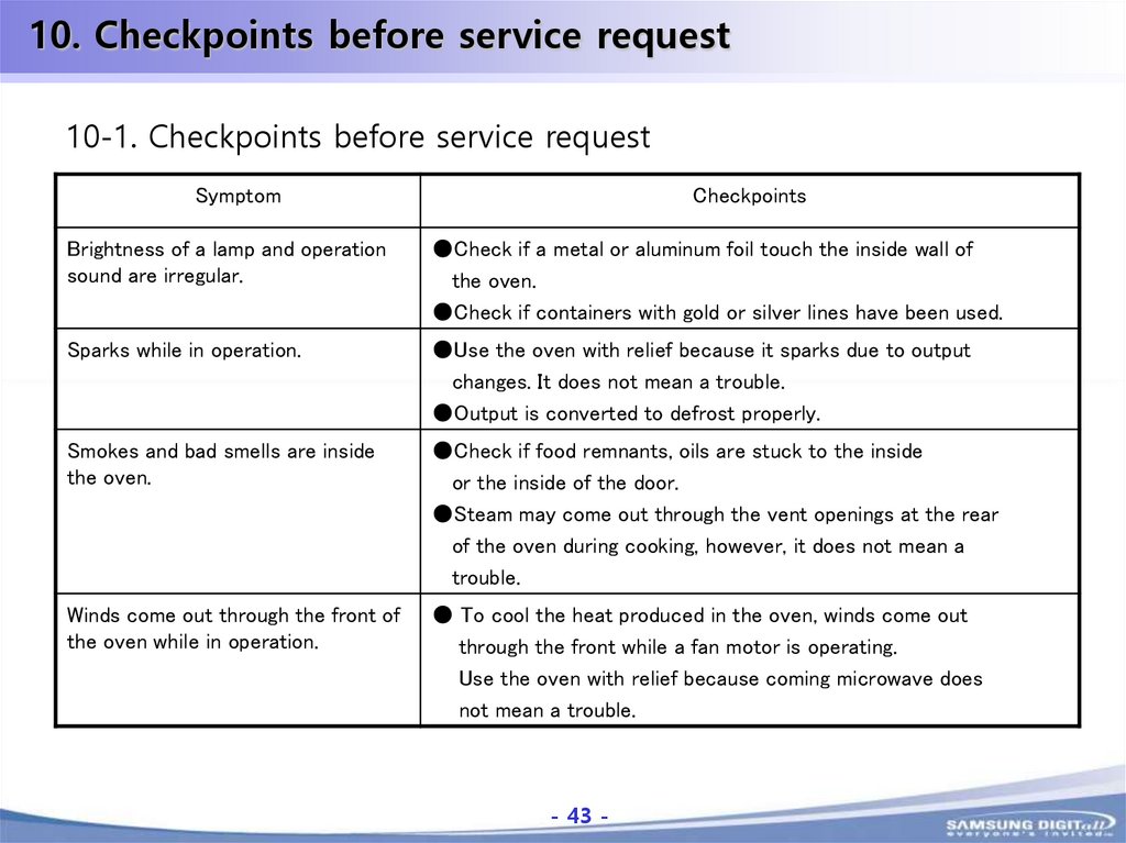
10. Checkpoints before service request10-1. Checkpoints before service request
Symptom
Checkpoints
Brightness of a lamp and operation
sound are irregular.
●Check if a metal or aluminum foil touch the inside wall of
the oven.
●Check if containers with gold or silver lines have been used.
Sparks while in operation.
●Use the oven with relief because it sparks due to output
changes. It does not mean a trouble.
●Output is converted to defrost properly.
Smokes and bad smells are inside
the oven.
●Check if food remnants, oils are stuck to the inside
or the inside of the door.
●Steam may come out through the vent openings at the rear
of the oven during cooking, however, it does not mean a
trouble.
Winds come out through the front of
the oven while in operation.
● To cool the heat produced in the oven, winds come out
through the front while a fan motor is operating.
Use the oven with relief because coming microwave does
not mean a trouble.
- 43 -
-43-
44.
SAMSUNGThanks
- 44 -
-44-