


 electronics
Similar presentations:


Service Manual. Operation training of new printer
1.
Table of ContentsI. Machine Introduction
1. Simple structure diagram············································································ (5)
2. Operating description········································································· (6)
3.Detailed description of main menu······························· ···· ···· ···· ······· (7~10)
II. Description of position and detailed functions
of motor and sensor
1. roller motor ·············································································· (11)
2. Press motor ···············································································(12)
3. Printing head motor ············································································(13)
4. Stepping motor ·········· ····································································(14)
5. Drawer sensor and box sensor··························································(15)
6. Press sensor and printing head sensor ·······················································(16)
7. Back cover sensor············································································(17)
8. Counting wheel sensor·········································································(18)
9. Film inspection sensor and film outlet sensor················································(19)
2.
III. PC software operating instructions1. VNC Software Using Manual···························································(20~21)
2. Introduction to the camera software interface·············································· (22)
2.1. Curve settings··· ······················································································································ (23)
2.2. Camera settings·························································································································· (24)
2.3. DICM settings·························································································································(25)
2.4. Printing channel settings·····················································································································(26)
3. New and old PC software settings and introduction·····································(27)
4. Differences in parameter settings between old and new versions··········(28~31)
IV. Description of image adjustment
1. Low-medium-high density judgment······································(32~33)
2. Gray scale·························· ·····························································(34)
3. Contrast ·····················································································(35)
V. Use of network testing tools and method for replacement of RFID card reader
1. Use of network testing tools ···································································(36)
2. Method for replacement of RFID card reader ································· ·······(37~38)
VI. PC software upgrading and description of APP settings
1. pc software upgrading··································································(39~40)
2. Description of APP settings ···································································(38)
3.
VII. Common problems and handling methods1. Common false alerts····································································(42~43)
2. Solution of different problems
2.1. Alert elimination··················································································································································(44)
2.2. Pick-up failure··················································································································································(45~48)
2.3. Host error··················································································································································(49~52)
2.4. Touch screen failure···············································································································································(53)
2.5. IPC on-off failure··········································································································································(54~55)
2.6. FPGA printing error··········································································································································(56)
2.7. FPGA status error··········································································································································(57)
2.8. Press motor error············································································································································(58~60)
2.9. Simultaneous reporting of multiple motor errors ···········································································································(61)
2.10. No film···················································································································································(62)
2.11. Film blocking················································································································································(63~64)
2.12. Over-temperature alert················································································································································(65~68)
2.13. No image available for the printed film··············································································································(69~70)
2.14. Print image irregularities·······································································································································(71~72)
3. Printer error code····································································(73~76)
4. Solution of GE and Siemens Print Image Problem·································· ( 77~78)
5. Description of each plug-in of the main control panel························(79~82)
6. Printer maintenance··········································································(83)
4.
Operation raining of new printerI: Installation and debugging of the printer
5.
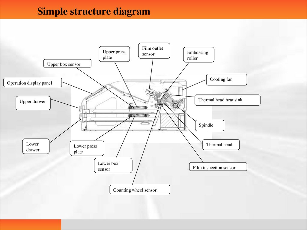
Simple structure diagramUpper press
plate
Film outlet
sensor
Embossing
roller
Upper box sensor
Cooling fan
Operation display panel
Thermal head heat sink
Upper drawer
Spindle
Lower
drawer
Thermal head
Lower press
plate
Lower box
sensor
Counting wheel sensor
Film inspection sensor
6.
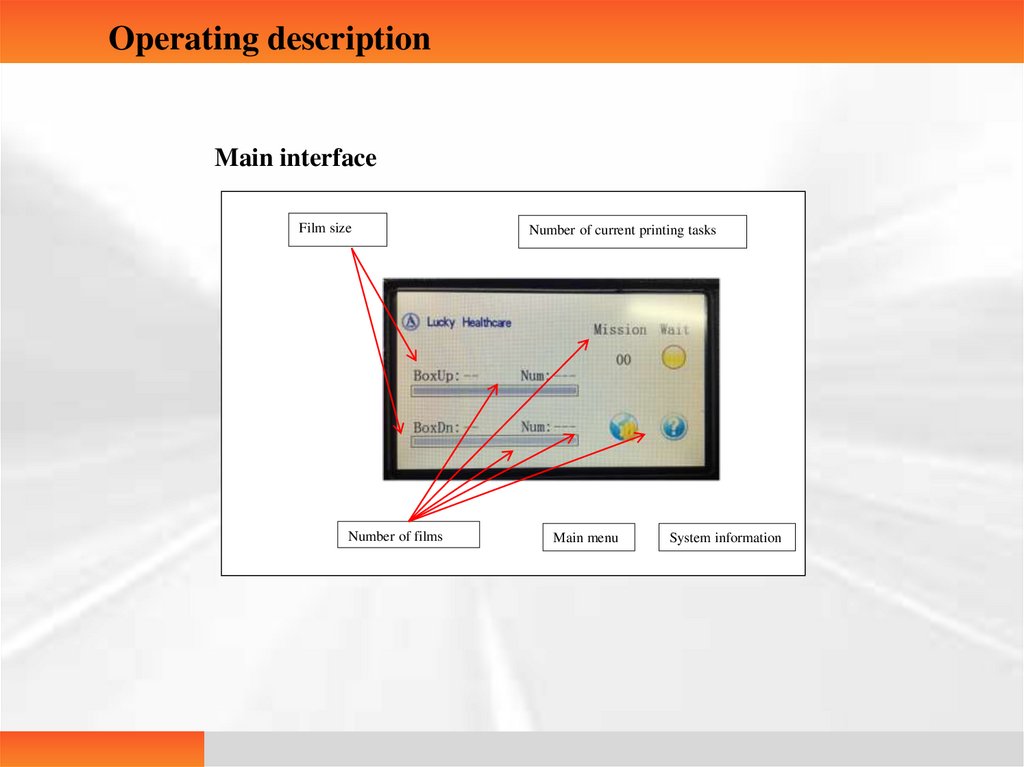
Operating descriptionMain interface
Film size
Number of films
Number of current printing tasks
Main menu
System information
7.
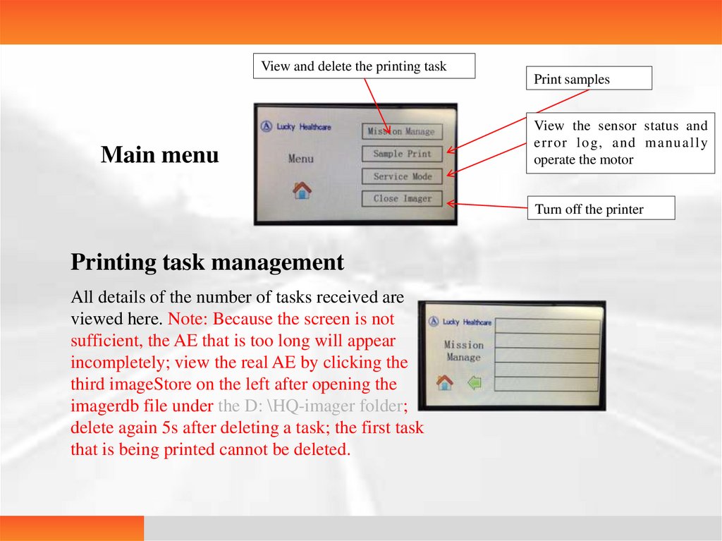
View and delete the printing taskPrint samples
Main menu
View the sensor status and
e rror log , and ma n u all y
operate the motor
Turn off the printer
Printing task management
All details of the number of tasks received are
viewed here. Note: Because the screen is not
sufficient, the AE that is too long will appear
incompletely; view the real AE by clicking the
third imageStore on the left after opening the
imagerdb file under the D: \HQ-imager folder;
delete again 5s after deleting a task; the first task
that is being printed cannot be deleted.
8.
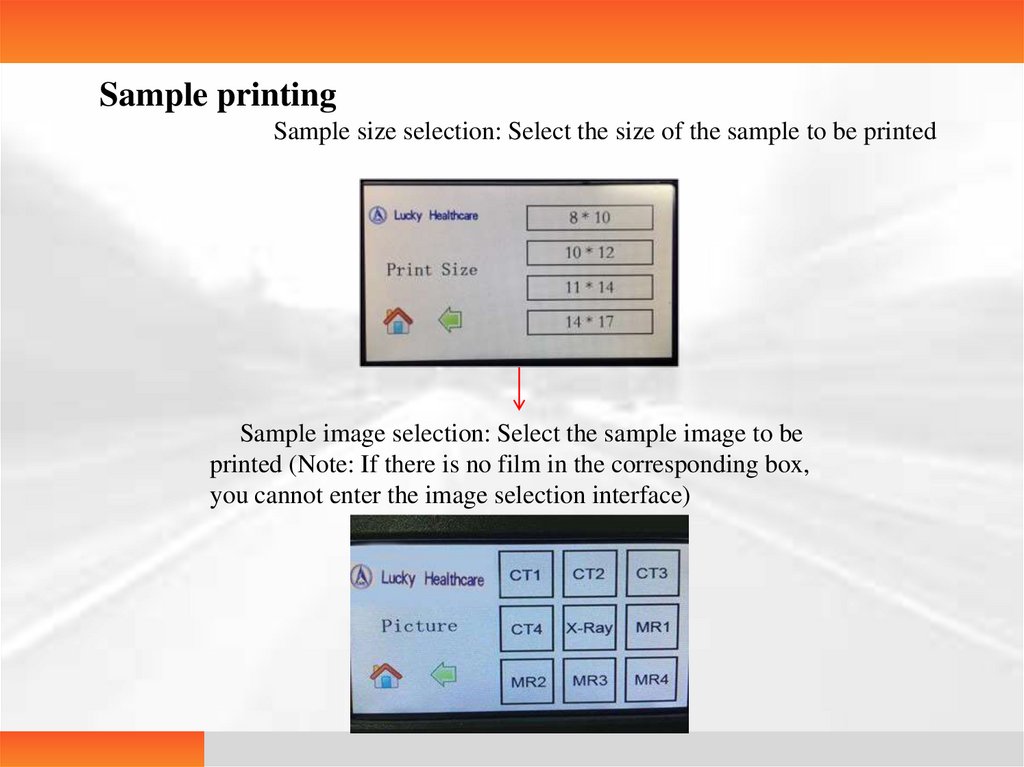
Sample printingSample size selection: Select the size of the sample to be printed
Sample image selection: Select the sample image to be
printed (Note: If there is no film in the corresponding box,
you cannot enter the image selection interface)
9.
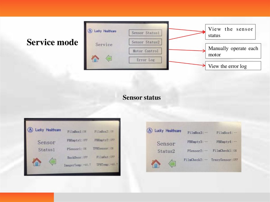
Vi e w t h e s e n s o rstatus
Service mode
Manually operate each
motor
View the error log
Sensor status
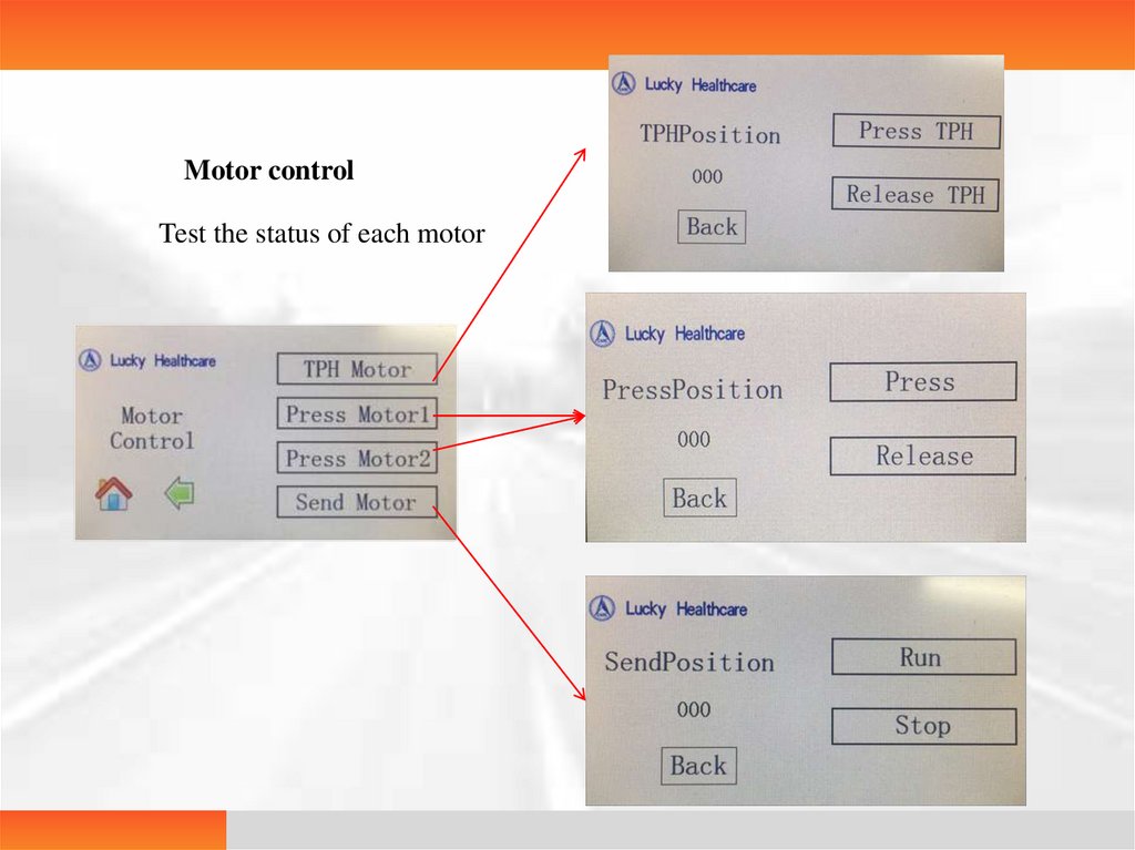
10.
Motor controlTest the status of each motor
11.
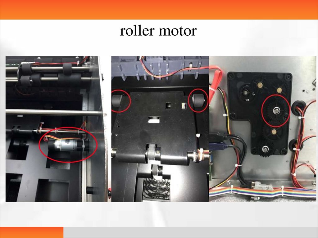
roller motor12.
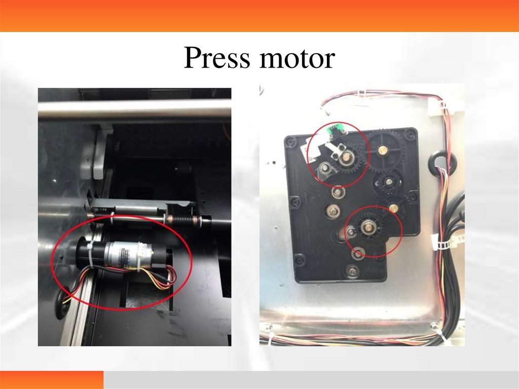
Press motor13.
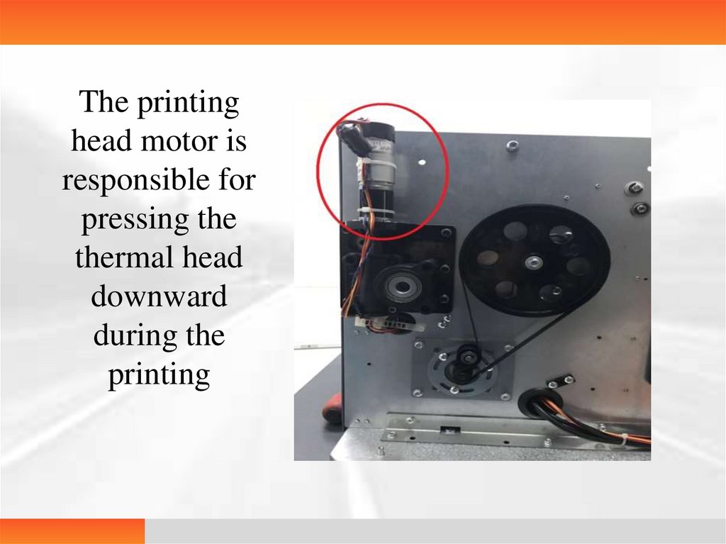
The printinghead motor is
responsible for
pressing the
thermal head
downward
during the
printing
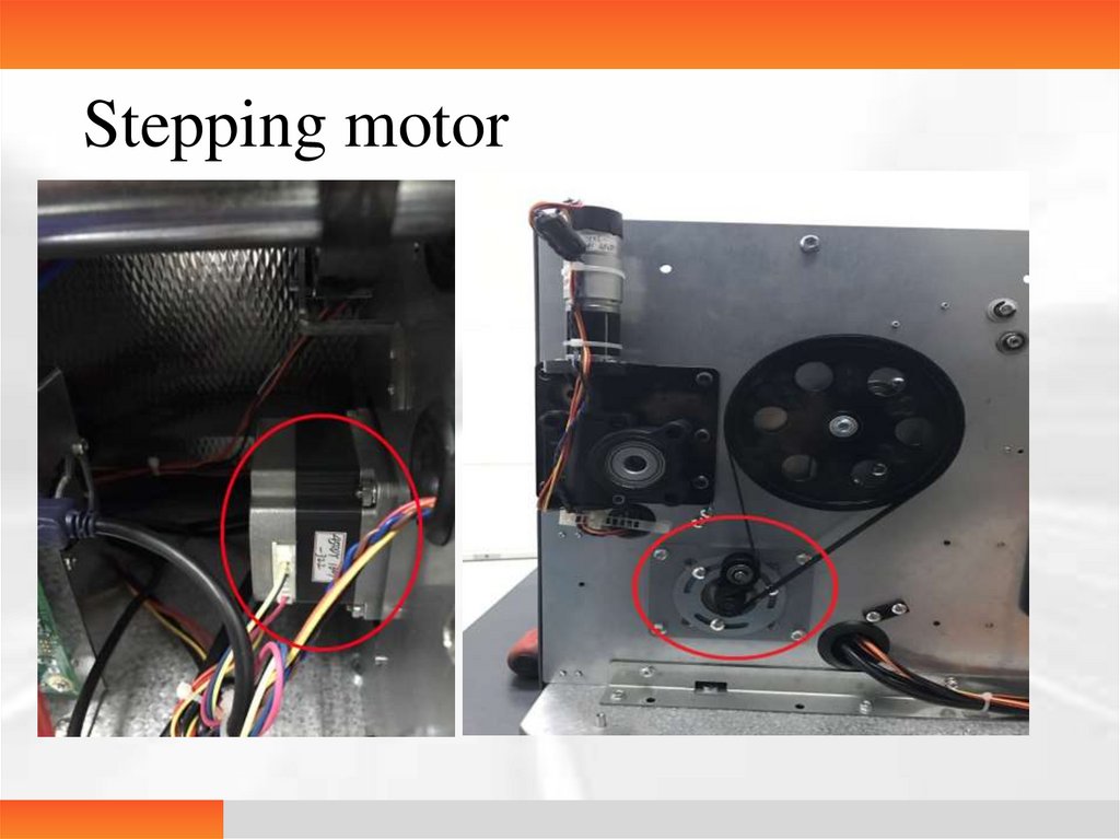
14.
Stepping motor15.
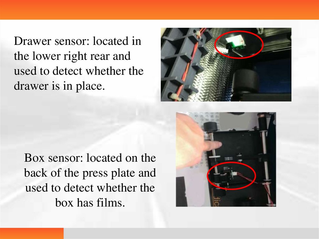
Drawer sensor: located inthe lower right rear and
used to detect whether the
drawer is in place.
Box sensor: located on the
back of the press plate and
used to detect whether the
box has films.
16.
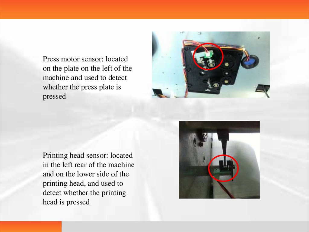
Press motor sensor: locatedon the plate on the left of the
machine and used to detect
whether the press plate is
pressed
Printing head sensor: located
in the left rear of the machine
and on the lower side of the
printing head, and used to
detect whether the printing
head is pressed
17.
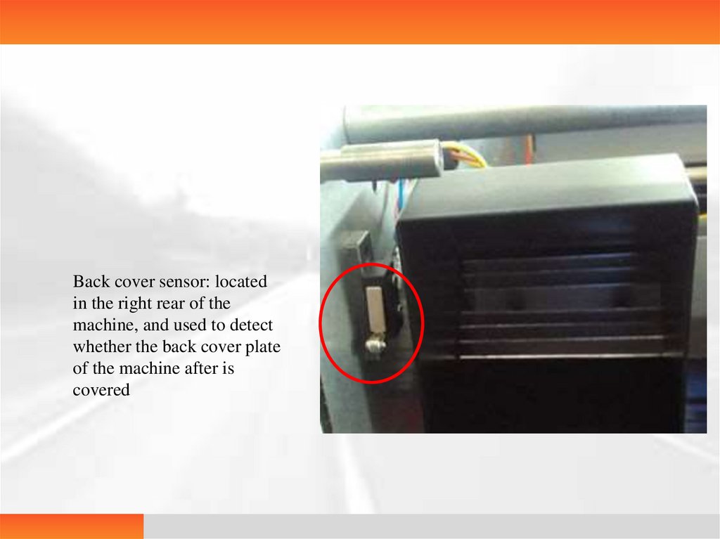
Back cover sensor: locatedin the right rear of the
machine, and used to detect
whether the back cover plate
of the machine after is
covered
18.
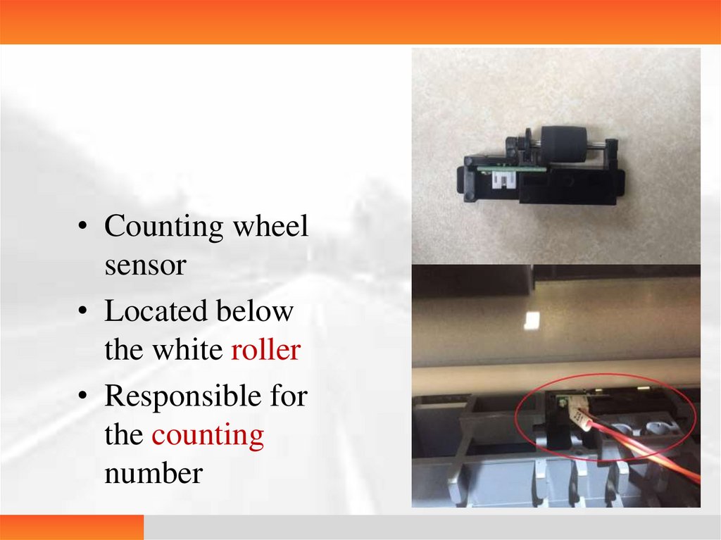
• Counting wheelsensor
• Located below
the white roller
• Responsible for
the counting
number
19.
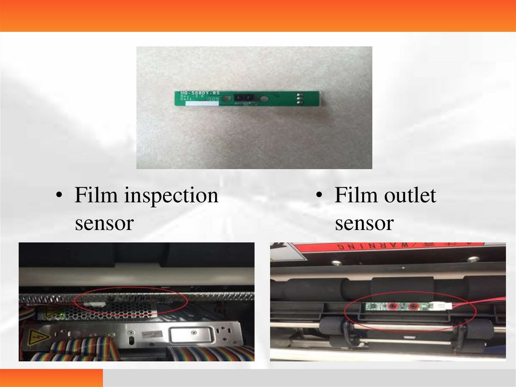
• Film inspectionsensor
• Film outlet
sensor
20.
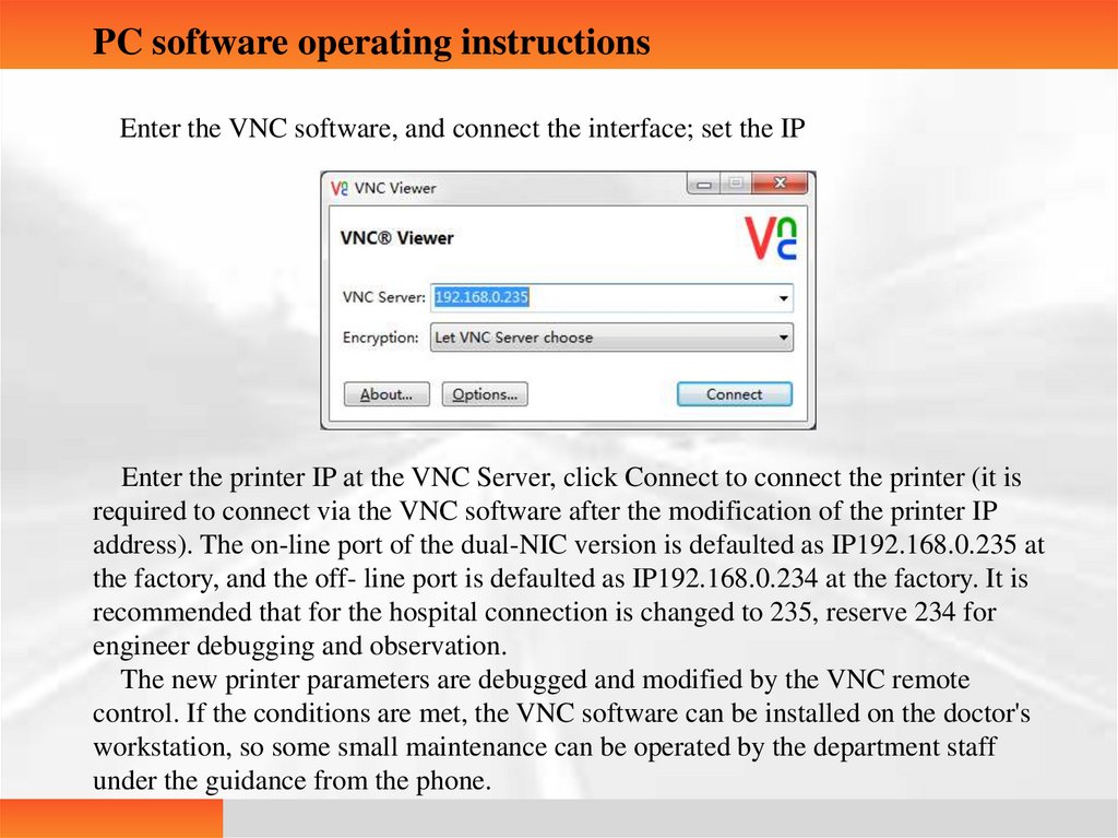
PC software operating instructionsEnter the VNC software, and connect the interface; set the IP
Enter the printer IP at the VNC Server, click Connect to connect the printer (it is
required to connect via the VNC software after the modification of the printer IP
address). The on-line port of the dual-NIC version is defaulted as IP192.168.0.235 at
the factory, and the off- line port is defaulted as IP192.168.0.234 at the factory. It is
recommended that for the hospital connection is changed to 235, reserve 234 for
engineer debugging and observation.
The new printer parameters are debugged and modified by the VNC remote
control. If the conditions are met, the VNC software can be installed on the doctor's
workstation, so some small maintenance can be operated by the department staff
under the guidance from the phone.
21.
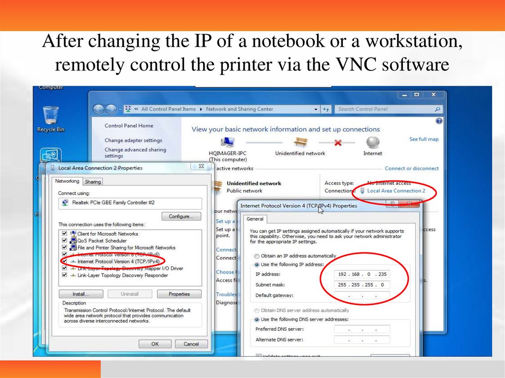
After changing the IP of a notebook or a workstation,remotely control the printer via the VNC software
22.
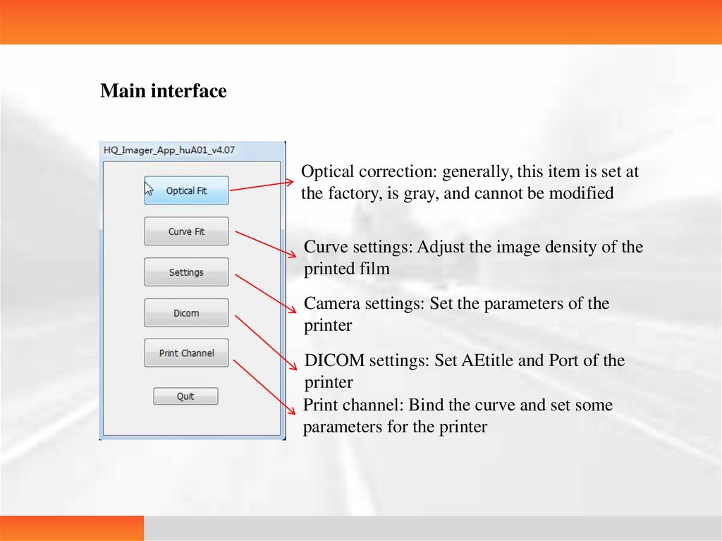
Main interfaceOptical correction: generally, this item is set at
the factory, is gray, and cannot be modified
Curve settings: Adjust the image density of the
printed film
Camera settings: Set the parameters of the
printer
DICOM settings: Set AEtitle and Port of the
printer
Print channel: Bind the curve and set some
parameters for the printer
23.
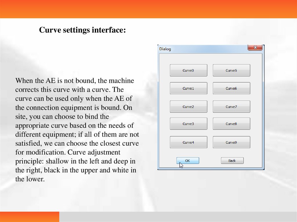
Curve settings interface:When the AE is not bound, the machine
corrects this curve with a curve. The
curve can be used only when the AE of
the connection equipment is bound. On
site, you can choose to bind the
appropriate curve based on the needs of
different equipment; if all of them are not
satisfied, we can choose the closest curve
for modification. Curve adjustment
principle: shallow in the left and deep in
the right, black in the upper and white in
the lower.
24.
Camera settingsPress position: The adjustment range is (0 ~ 50), the typical value of the scrapper machine is 36, and the typical value of the sucker machine is 16; the press positions 1 ~ 4
of the press motor correspond to boxes 1 ~ 4 from top to bottom. Adjustment basis of values: the film can be delivered when the tray is full of films and when the tray only has one
film.
Start position (sending position): The adjustment range is (0 ~ 80). The typical range of the machine with a retreat action is 35 - 45, and the typical range of the machine
without a retreat action is 25 – 35; adjust the upper white edge location of the print picture with the value adjustment basis as follows: depend on the distance from the image of the
printed picture to the top of the film, i.e. the upper white edge we called; if the upper white edge of a machine with a retreat action is too wide, increase the value; if the upper white
edge of a machine without a retreat action is too wide, decrease the value.
Print length (print width): adjust the length of the entire image, depending on the lower white edge; the typical value is 0, and the adjustment range is -7 ~ +7 (the range is -3
~ +3 for the software version 2.09 and before); the greater the value, the smaller the lower white edge.
Note: If NewCom in app.Config is TRUE, the sending position (start position) and the print length shall be changed in the print channel.
Pre-pressing position: The adjustment range is (0 ~ 100). It is the position where the printing head is pressed down for the first time, so that the film can be sent to the
printing position properly; if the value is too large, this may cause that the film cannot be sent to the printing position.
Printing position: It is the position where the printing head is pressed down for the second time; if it is too low, the image may not be printed; if it is too high, the film may
be too coiled and deformed.
Film outlet position: The typical value is (7 ~ 10); the film outlet time after the completion of printing, i.e. the working time of the main motor.
Preheat temperature: The adjustment range is (0 ~ 50 ℃); the preheat temperature of the printing head is 40 ℃ (which can be set; the temperature shall be maintained even
the machine does not print, which is generally not modified)
Alert temperature: The adjustment range is (0 ~ 80 ℃); the alert temperature of the printing head is 60 ℃ (which can be set; it is the maximum temperature allowed by the
printing head; if it is exceed this value, the printing head stops heating, which is generally not modified)
25.
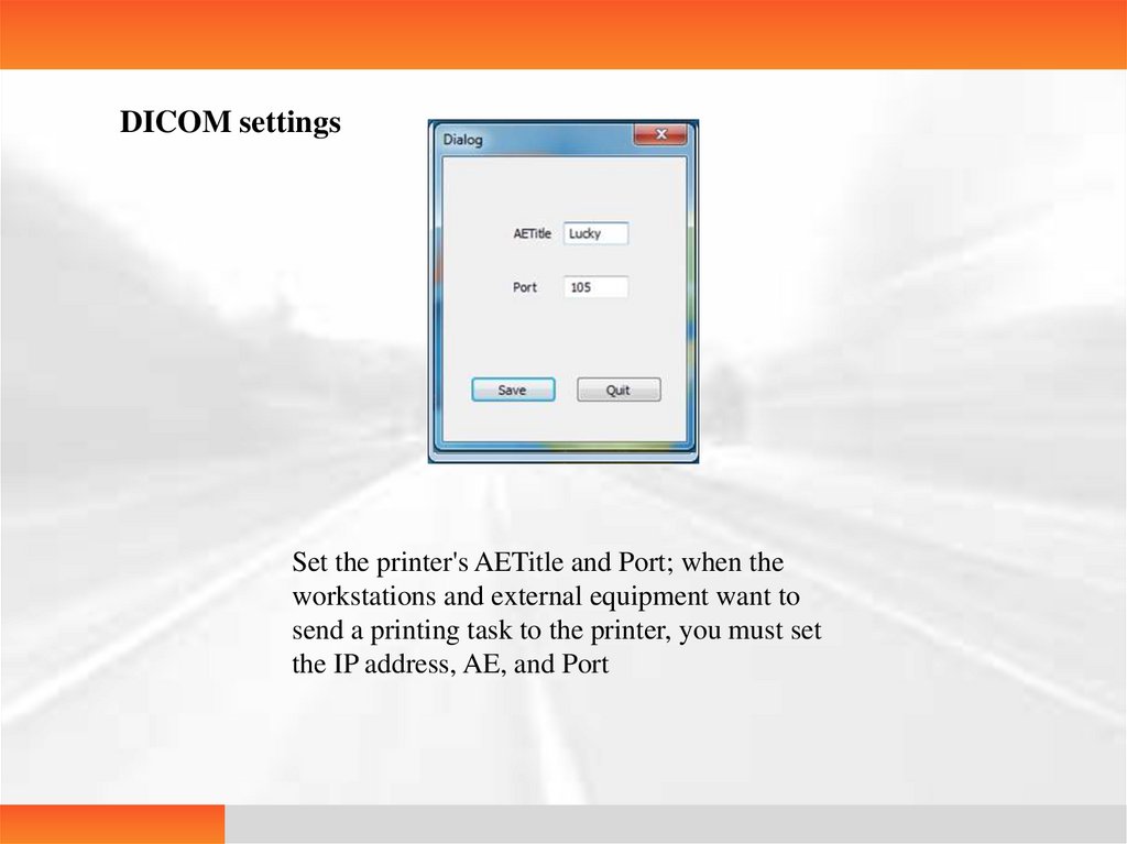
DICOM settingsSet the printer's AETitle and Port; when the
workstations and external equipment want to
send a printing task to the printer, you must set
the IP address, AE, and Port
26.
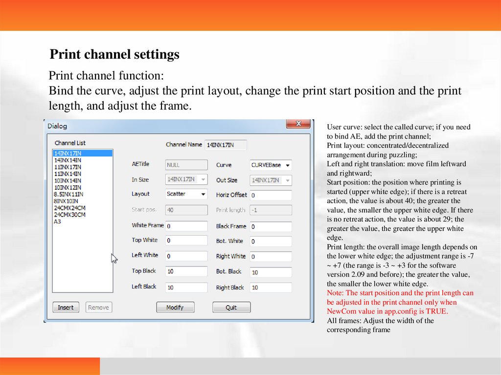
Print channel settingsPrint channel function:
Bind the curve, adjust the print layout, change the print start position and the print
length, and adjust the frame.
User curve: select the called curve; if you need
to bind AE, add the print channel;
Print layout: concentrated/decentralized
arrangement during puzzling;
Left and right translation: move film leftward
and rightward;
Start position: the position where printing is
started (upper white edge); if there is a retreat
action, the value is about 40; the greater the
value, the smaller the upper white edge. If there
is no retreat action, the value is about 29; the
greater the value, the greater the upper white
edge.
Print length: the overall image length depends on
the lower white edge; the adjustment range is -7
~ +7 (the range is -3 ~ +3 for the software
version 2.09 and before); the greater the value,
the smaller the lower white edge.
Note: The start position and the print length can
be adjusted in the print channel only when
NewCom value in app.config is TRUE.
All frames: Adjust the width of the
corresponding frame
27.
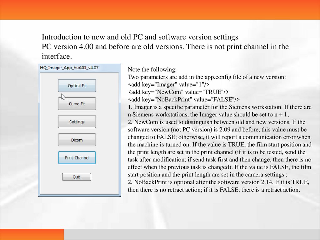
Introduction to new and old PC and software version settingsPC version 4.00 and before are old versions. There is not print channel in the
interface.
Note the following:
Two parameters are add in the app.config file of a new version:
<add key="Imager" value="1"/>
<add key="NewCom" value="TRUE"/>
<add key="NoBackPrint" value="FALSE"/>
1. Imager is a specific parameter for the Siemens workstation. If there are
n Siemens workstations, the Imager value should be set to n + 1;
2. NewCom is used to distinguish between old and new versions. If the
software version (not PC version) is 2.09 and before, this value must be
changed to FALSE; otherwise, it will report a communication error when
the machine is turned on. If the value is TRUE, the film start position and
the print length are set in the print channel (if it is to be tested, send the
task after modification; if send task first and then change, then there is no
effect when the previous task is changed). If the value is FALSE, the film
start position and the print length are set in the camera settings ;
2. NoBackPrint is optional after the software version 2.14. If it is TRUE,
then there is no retract action; if it is FALSE, there is a retract action.
28.
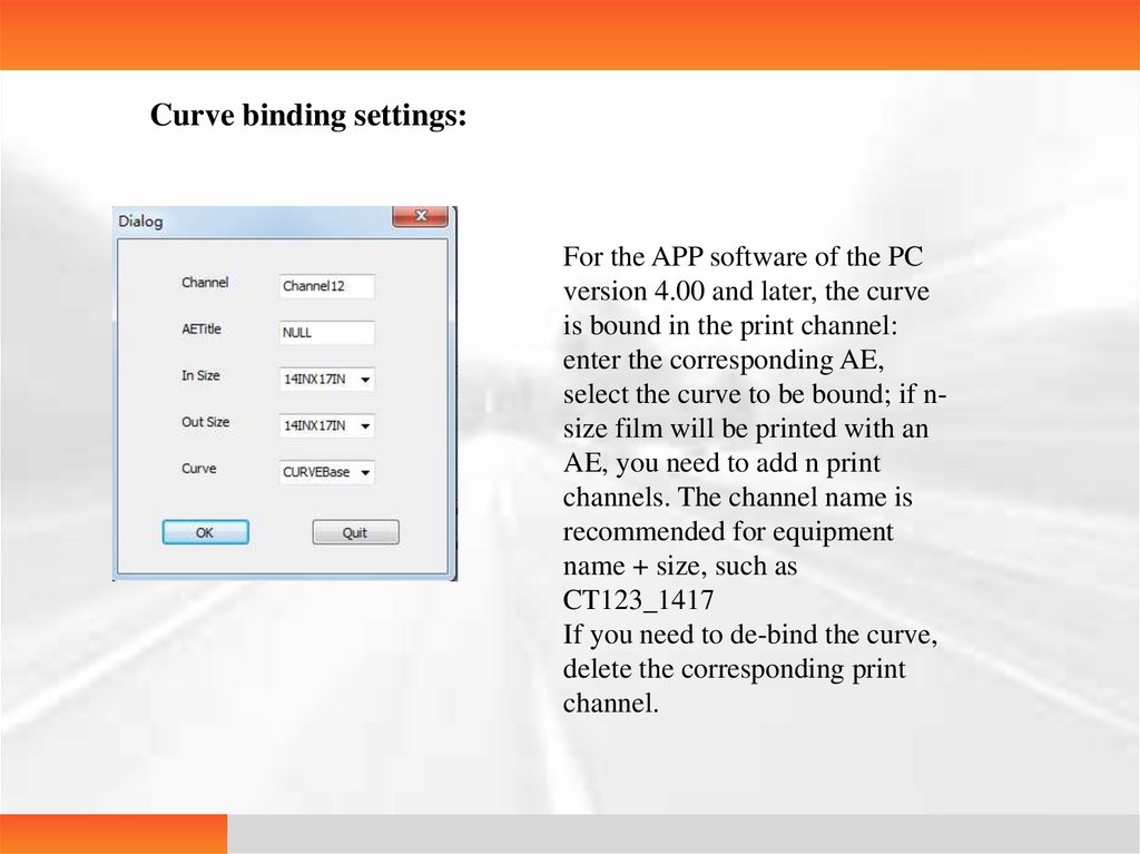
Curve binding settings:For the APP software of the PC
version 4.00 and later, the curve
is bound in the print channel:
enter the corresponding AE,
select the curve to be bound; if nsize film will be printed with an
AE, you need to add n print
channels. The channel name is
recommended for equipment
name + size, such as
CT123_1417
If you need to de-bind the curve,
delete the corresponding print
channel.
29.
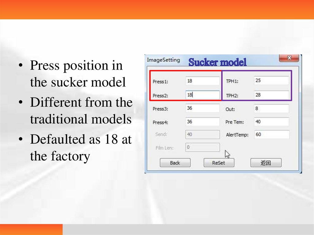
• Press position inthe sucker model
• Different from the
traditional models
• Defaulted as 18 at
the factory
30.
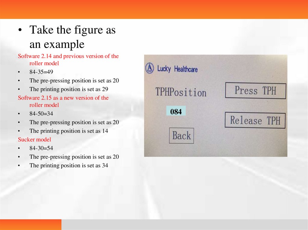
• Take the figure asan example
Software 2.14 and previous version of the
roller model
84-35=49
The pre-pressing position is set as 20
The printing position is set as 29
Software 2.15 as a new version of the
roller model
84-50=34
The pre-pressing position is set as 20
The printing position is set as 14
Sucker model
84-30=54
The pre-pressing position is set as 20
The printing position is set as 34
084
31.
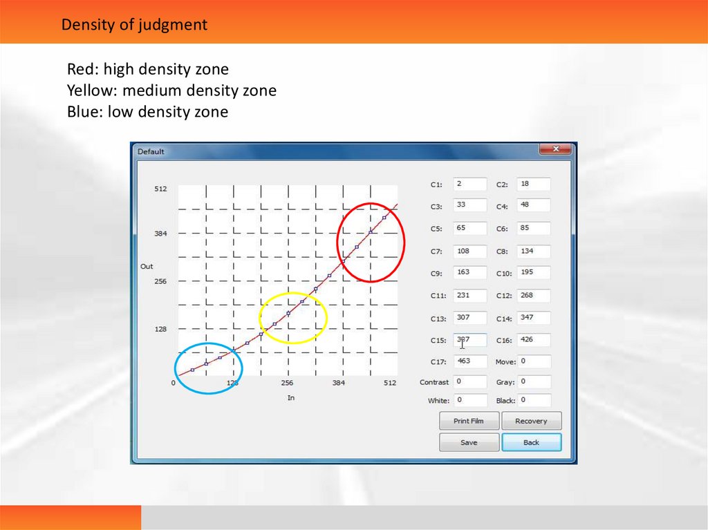
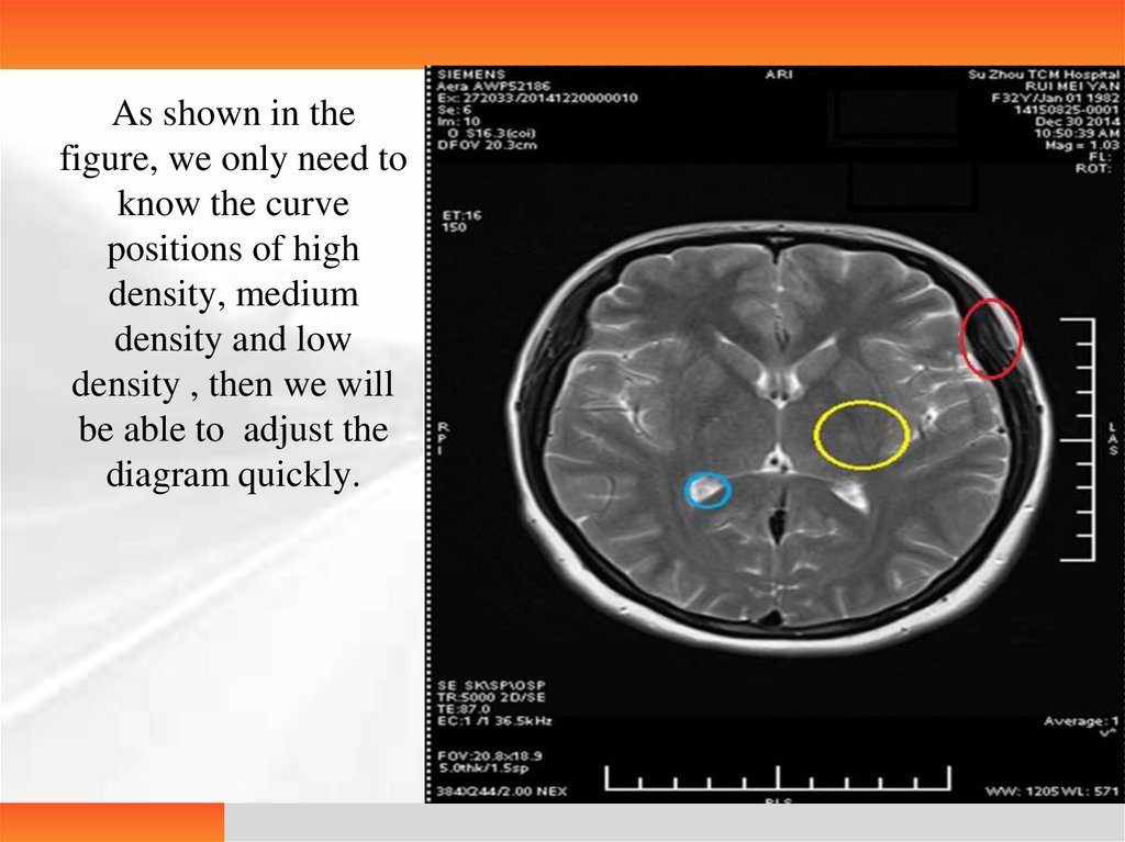
Density of judgmentRed: high density zone
Yellow: medium density zone
Blue: low density zone
32.
As shown in thefigure, we only need to
know the curve
positions of high
density, medium
density and low
density , then we will
be able to adjust the
diagram quickly.
33.
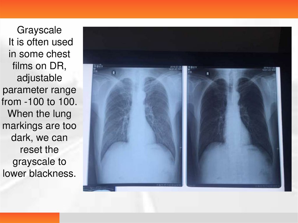
GrayscaleIt is often used
in some chest
films on DR,
adjustable
parameter range
from -100 to 100.
When the lung
markings are too
dark, we can
reset the
grayscale to
lower blackness.
34.
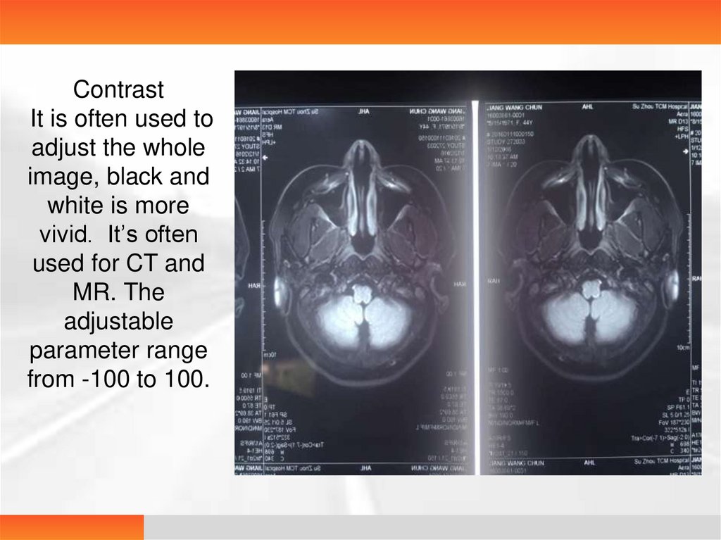
ContrastIt is often used to
adjust the whole
image, black and
white is more
vivid. It’s often
used for CT and
MR. The
adjustable
parameter range
from -100 to 100.
35.
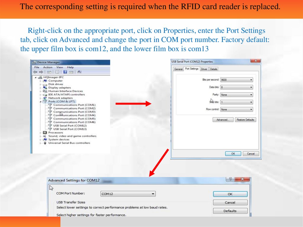
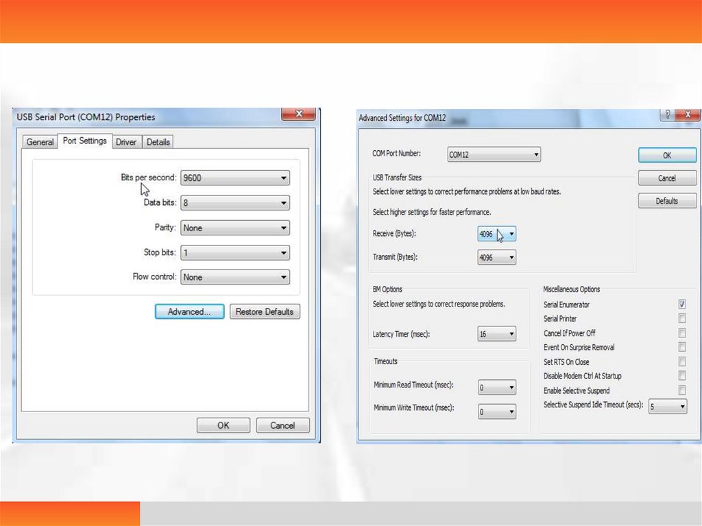
The corresponding setting is required when the RFID card reader is replaced.Right-click on the appropriate port, click on Properties, enter the Port Settings
tab, click on Advanced and change the port in COM port number. Factory default:
the upper film box is com12, and the lower film box is com13
36.
37.
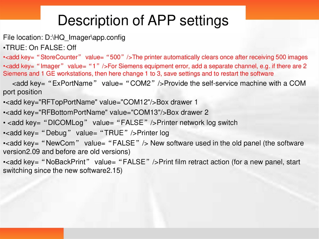
Description of APP settingsFile location: D:\HQ_Imager\app.config
•TRUE: On FALSE: Off
•<add key=“StoreCounter” value=“500”/>The printer automatically clears once after receiving 500 images
•<add key=“Imager” value=“1”/>For Siemens equipment error, add a separate channel, e.g. if there are 2
Siemens and 1 GE workstations, then here change 1 to 3, save settings and to restart the software
<add key=“ExPortName” value=“COM2”/>Provide the self-service machine with a COM
port position
•<add key="RFTopPortName" value="COM12"/>Box drawer 1
•<add key="RFBottomPortName" value="COM13"/>Box drawer 2
• <add key=“DICOMLog” value=“FALSE”/>Printer network log switch
•<add key=“Debug” value=“TRUE”/>Printer log
•<add key=“NewCom” value=“FALSE”/> New software used in the old panel (the software
version2.09 and before are old versions)
•<add key=“NoBackPrint” value=“FALSE”/>Print film retract action (for a new panel, start
switching since the new software2.15)
38.
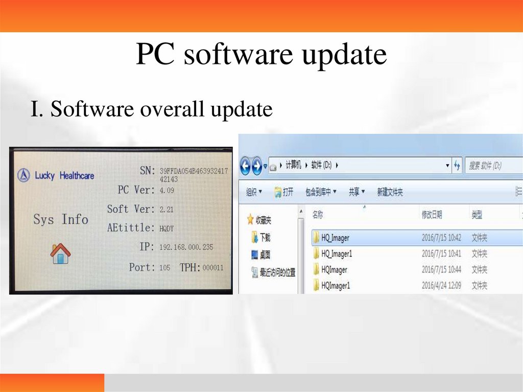
PC software updateI. Software overall update
39.
• Update steps• 1. After VNC is connected to the printer, exit the software
• 2. Delete all the files in the path of D:\HQ_Imager\Dicom\Dest\data under
the original D root directory. Rename HQ_Imager followed by a 1 as
HQ_Imager1
• 3. Put the new HQ_Imager in the D root directory
• 4. Run the desktop HQ_Imager_App and click on the DICOM settings to
check AEtitle and Port
• The entire upgrade process ends. DICOM settings: set AEtitle and Port of
the printer
• Upgrading precautions
• PC version 1.15 and before can only be upgraded to 2.03
• PC version 3.00 can be upgraded to the latest 4.05
40.
Common error• Drawer 1 opened : Check the drawer sensor 1
• Drawer 2 opened : Check the drawer sensor 2
• Printing head plug-in error : Check whether the 64 cables are
inserted firmly
• FPGA printing error : Print timeout
• Film blocked : The film is not released or picked up
• Printing head temperature is too high : Over-temperature alert
41.
Back cover error: Back cover opened
Communication error: The host software is not turned on
Press motor error: The press motor cable is not inserted firmly or the main control
panel cable is disconnected
Sending motor error: The sending motor cable is not inserted firmly
Printing head motor error: The printing head motor cable is not inserted firmly or
the main control panel cable is disconnected
Display screen error: The display screen cable is not inserted firmly or the main
control panel cable is not inserted firmly.
FPGA status error: Computer crashes or the USB cable between the motherboard
and the computer is not under good contact or not connected
Host error: When the machine is turned on, the computer host is not turned on or
the APP is not running
Print sensor error: Check the sensor cable of the printing head motor
Press motor sensor error: Press motor sensor
Film size error: Film does not match
No film: It displays the number of chips but actually there is no film
Film not authorized: The used film is not authorized
42.
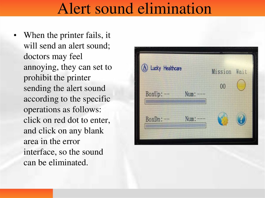
Alert sound elimination• When the printer fails, it
will send an alert sound;
doctors may feel
annoying, they can set to
prohibit the printer
sending the alert sound
according to the specific
operations as follows:
click on red dot to enter,
and click on any blank
area in the error
interface, so the sound
can be eliminated.
43.
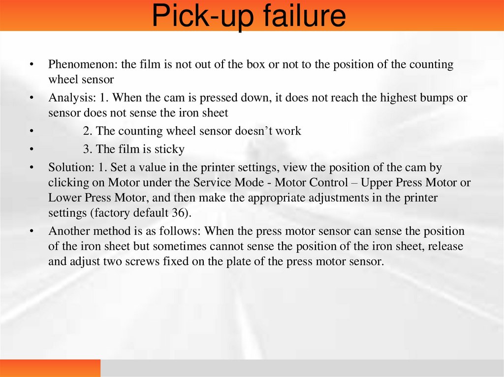
Pick-up failurePhenomenon: the film is not out of the box or not to the position of the counting
wheel sensor
Analysis: 1. When the cam is pressed down, it does not reach the highest bumps or
sensor does not sense the iron sheet
2. The counting wheel sensor doesn’t work
3. The film is sticky
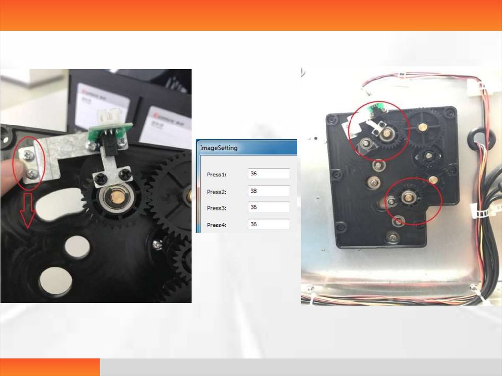
Solution: 1. Set a value in the printer settings, view the position of the cam by
clicking on Motor under the Service Mode - Motor Control – Upper Press Motor or
Lower Press Motor, and then make the appropriate adjustments in the printer
settings (factory default 36).
Another method is as follows: When the press motor sensor can sense the position
of the iron sheet but sometimes cannot sense the position of the iron sheet, release
and adjust two screws fixed on the plate of the press motor sensor.
44.
45.
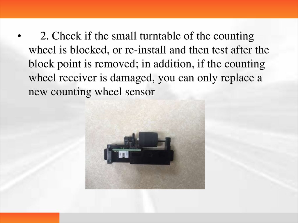
2. Check if the small turntable of the counting
wheel is blocked, or re-install and then test after the
block point is removed; in addition, if the counting
wheel receiver is damaged, you can only replace a
new counting wheel sensor
46.
3. Many films are stuck due to dampness in
the rainy season, so they are clamped in the
print channel and even cannot be released from
the box. You can simulate whether the film
release process with your fingers to determine
whether it is caused by sticky film. For the
solution, you can only take out the current
films, separate them one by one, and then put
them in the box for continued use.
47.
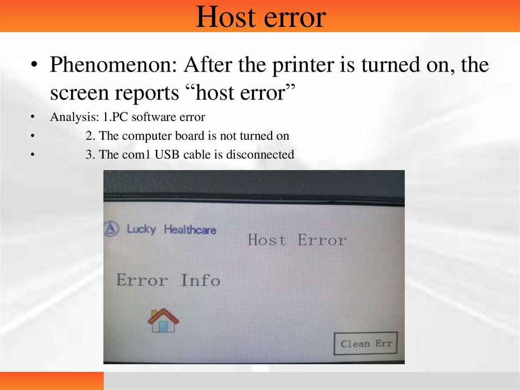
Host error• Phenomenon: After the printer is turned on, the
screen reports “host error”
Analysis: 1.PC software error
2. The computer board is not turned on
3. The com1 USB cable is disconnected
48.
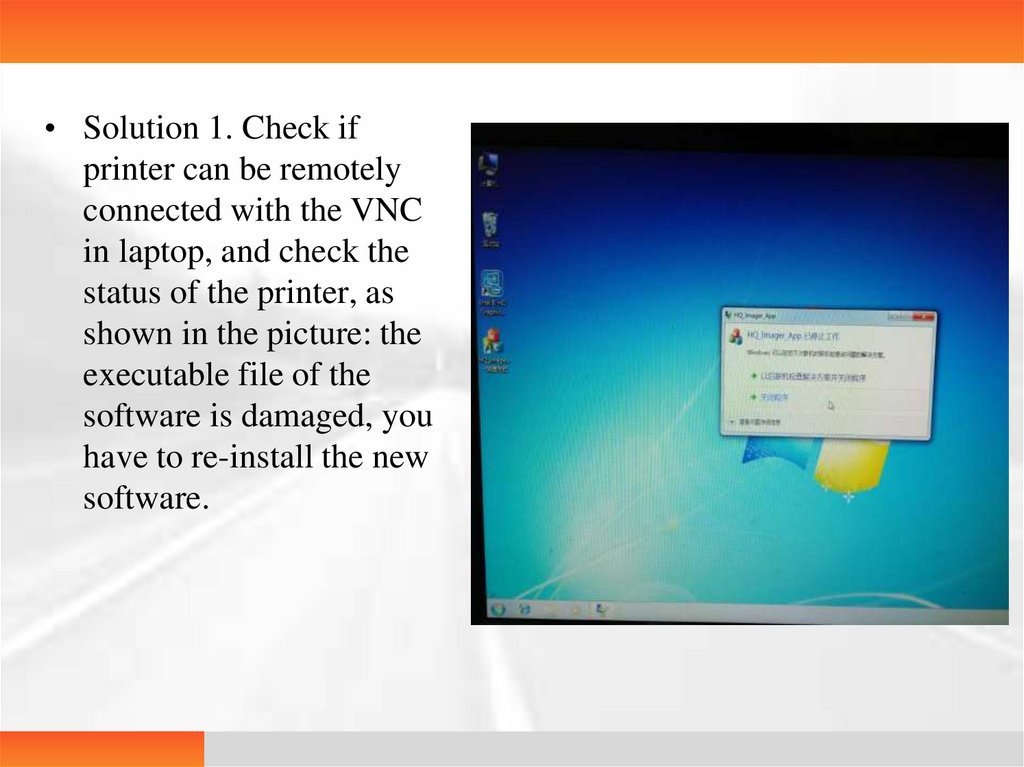
• Solution 1. Check ifprinter can be remotely
connected with the VNC
in laptop, and check the
status of the printer, as
shown in the picture: the
executable file of the
software is damaged, you
have to re-install the new
software.
49.
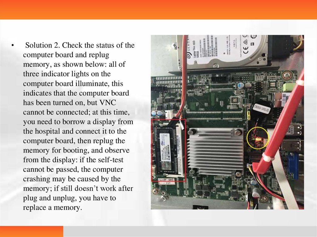
Solution 2. Check the status of the
computer board and replug
memory, as shown below: all of
three indicator lights on the
computer board illuminate, this
indicates that the computer board
has been turned on, but VNC
cannot be connected; at this time,
you need to borrow a display from
the hospital and connect it to the
computer board, then replug the
memory for booting, and observe
from the display: if the self-test
cannot be passed, the computer
crashing may be caused by the
memory; if still doesn’t work after
plug and unplug, you have to
replace a memory.
50.
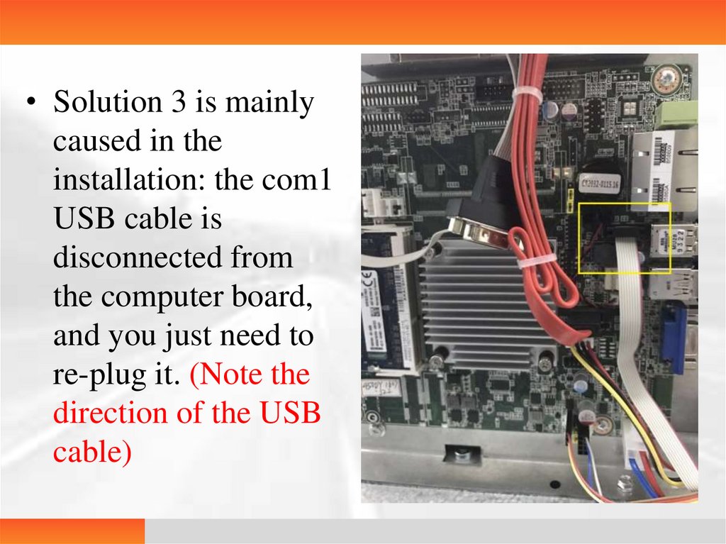
• Solution 3 is mainlycaused in the
installation: the com1
USB cable is
disconnected from
the computer board,
and you just need to
re-plug it. (Note the
direction of the USB
cable)
51.
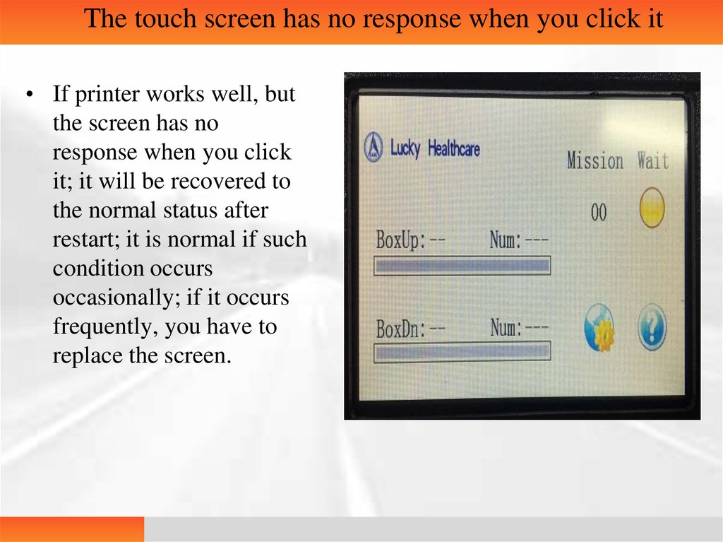
The touch screen has no response when you click it• If printer works well, but
the screen has no
response when you click
it; it will be recovered to
the normal status after
restart; it is normal if such
condition occurs
occasionally; if it occurs
frequently, you have to
replace the screen.
52.
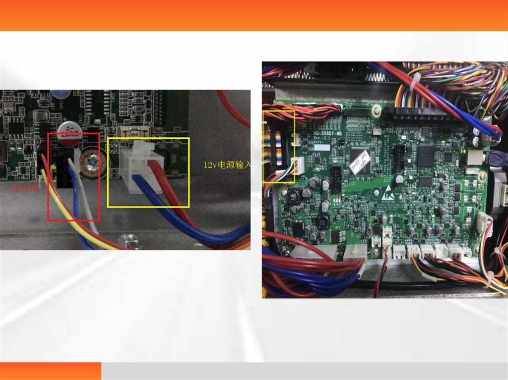
IPC on-off failure• The IPC fails to be turned on or off when the printer
is turned on or off normally.
• Analysis 1. signal line is not firmly connected
2.12v power line is not powered on
• Solution 1. In the power off state, re-plug the signal lines at the
lower right corner of the computer board and the upper left of
the main control panel.
• 2. Measure whether the 12v input end of the computer board
has the voltage input with a multimeter; if there is no voltage
input, then check whether the 12v switch power has 12v
output to identify the problem.
53.
54.
FPGA printing error• In the normal printing process, it suddenly
reports the FPGA print error and at the same
time prints out a full-white film without the
image, the task queue still exists, they can
continue to come out if the error is removed,
which only exists in sizes of 11X14 and 10X12.
• Analysis 1. There is a Bug in the main board
program
• Solution 1. Upgrade or replace the main control
panel for the printer with this error.
55.
FPGA status error• Phenomenon: FPGA status error is often reported during
printing
• Analysis: 1. The main control panel chip is damaged
2. The memory is damaged
3. The USB cable between the computer and the main
control panel is not firmly connected
• Solution: 1. Replace the main control panel
2. Unplug the memory, and wipe the position of the
memory in contact with the computer board with a rubber or
anhydrous alcohol; if there is still an error after re-installation,
then replace the memory.
3. Replace a new USB cable
56.
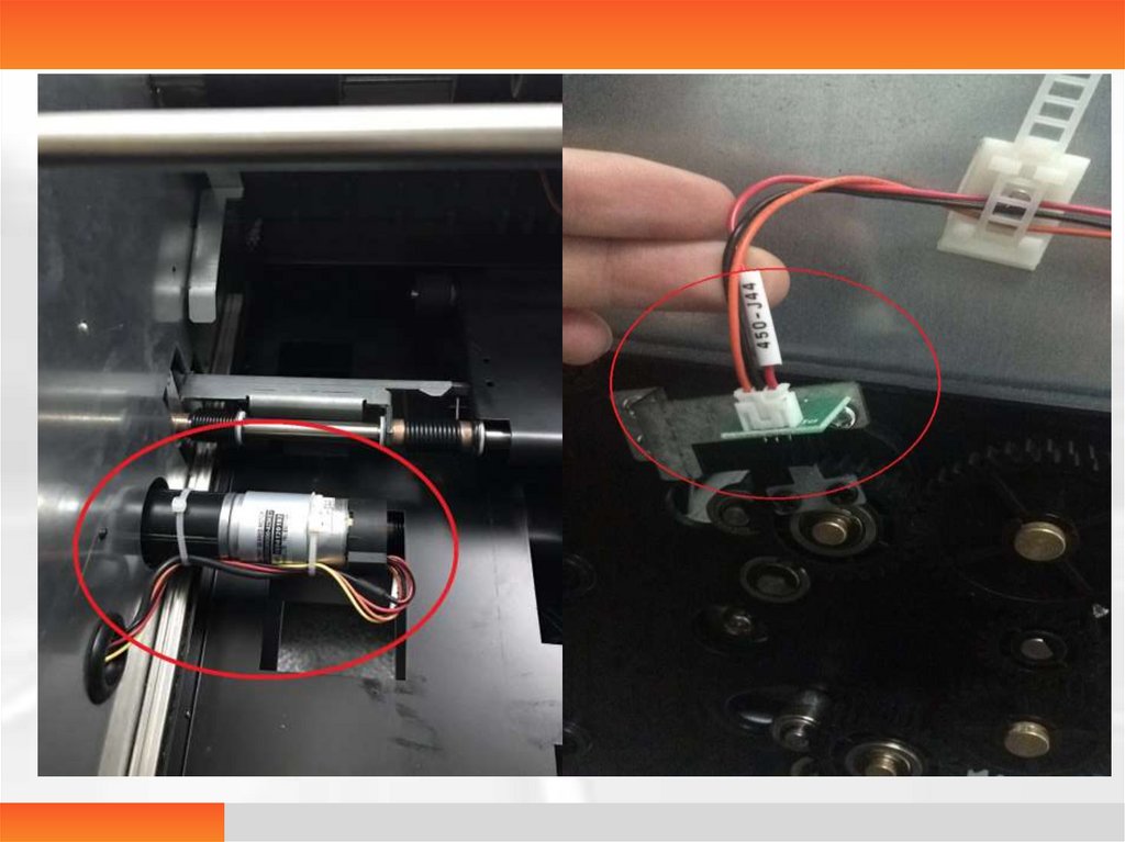
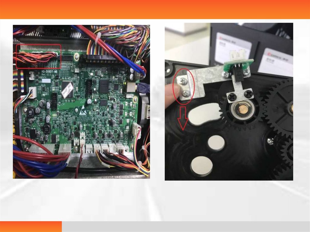
Press motor error• Press motor error is reported after booting and during the
printing
• Analysis 1. Cables on the press motor and the sensor or the
connection line on the main control panel are not firmly
connected
2. The press motor sensor is not in the correct position
• Solution 1.In the power off state, plug the connection lines on
the press motor, the sensor and the main control panel.
2. Loosen and downwards adjust the two screws fixed
on the plate of the press motor sensor.
57.
58.
59.
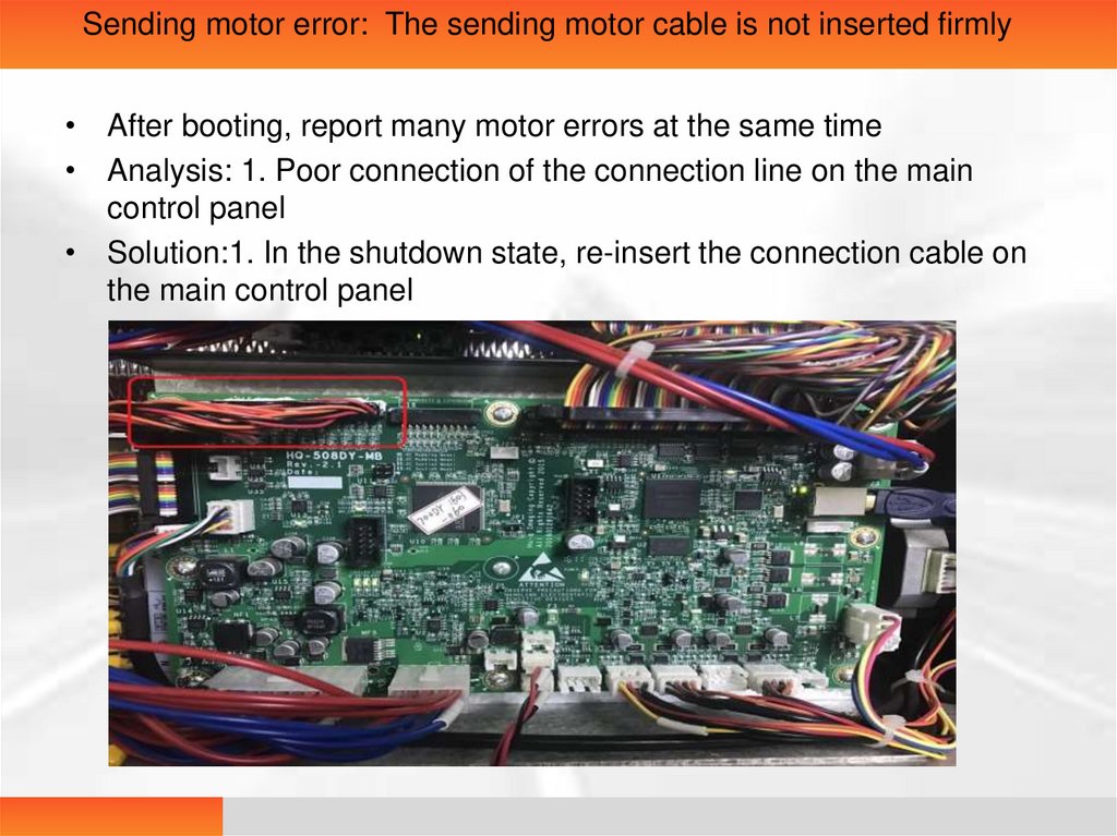
Sending motor error: The sending motor cable is not inserted firmly• After booting, report many motor errors at the same time
• Analysis: 1. Poor connection of the connection line on the main
control panel
• Solution:1. In the shutdown state, re-insert the connection cable on
the main control panel
60.
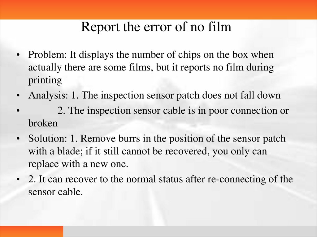
Report the error of no film• Problem: It displays the number of chips on the box when
actually there are some films, but it reports no film during
printing
• Analysis: 1. The inspection sensor patch does not fall down
2. The inspection sensor cable is in poor connection or
broken
• Solution: 1. Remove burrs in the position of the sensor patch
with a blade; if it still cannot be recovered, you only can
replace with a new one.
• 2. It can recover to the normal status after re-connecting of the
sensor cable.
61.
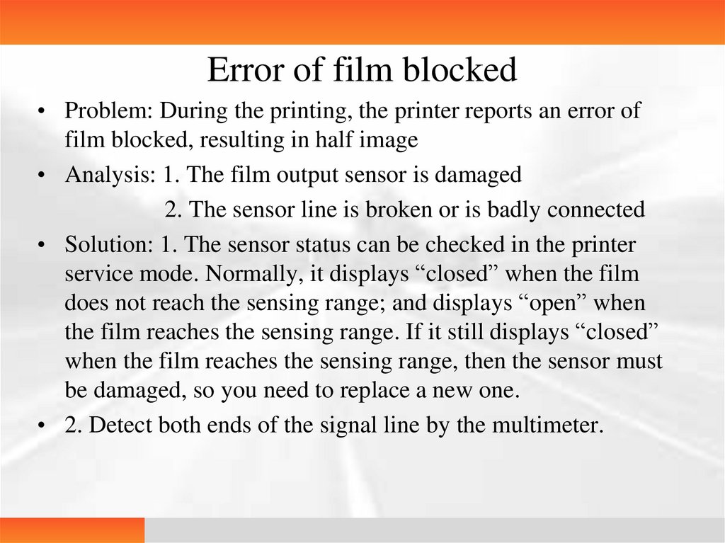
Error of film blocked• Problem: During the printing, the printer reports an error of
film blocked, resulting in half image
• Analysis: 1. The film output sensor is damaged
2. The sensor line is broken or is badly connected
• Solution: 1. The sensor status can be checked in the printer
service mode. Normally, it displays “closed” when the film
does not reach the sensing range; and displays “open” when
the film reaches the sensing range. If it still displays “closed”
when the film reaches the sensing range, then the sensor must
be damaged, so you need to replace a new one.
• 2. Detect both ends of the signal line by the multimeter.
62.
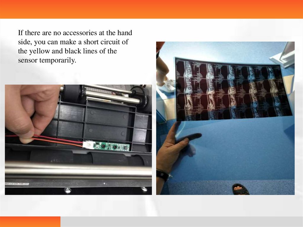
If there are no accessories at the handside, you can make a short circuit of
the yellow and black lines of the
sensor temporarily.
63.
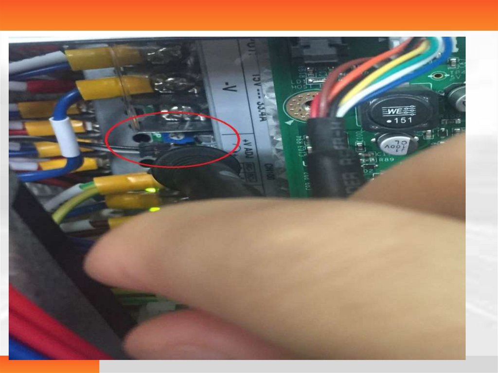
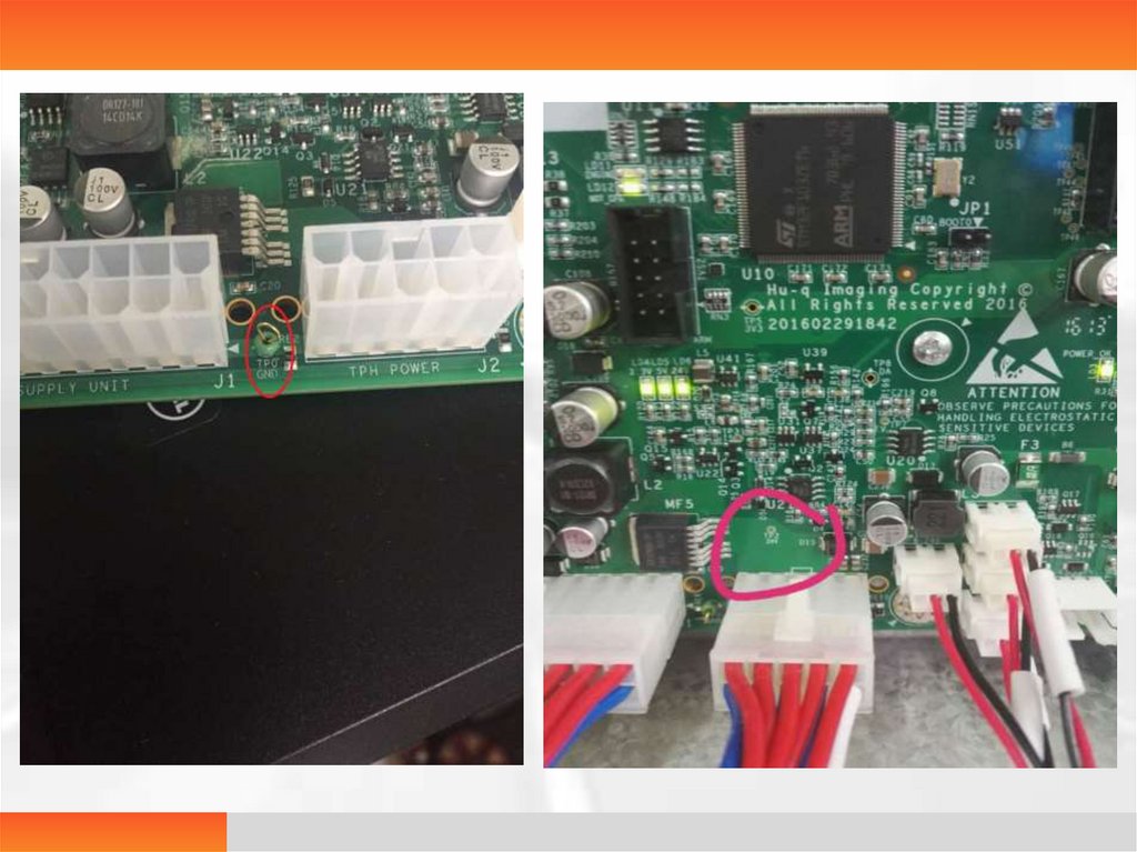
508 high temperature during printingProblem: The printed film is too dark due to
high temperature, resulting from the printer
working continuously
Solution: 1. As long as the printer is powered on,
put a multimeter on 24V and TPOGND of the
main control panel, and counterclockwise turn
one fifth of a turn on the potentiometer of the
switch power with a screwdriver to adjust to 18V
from the original 19V.
64.
65.
66.
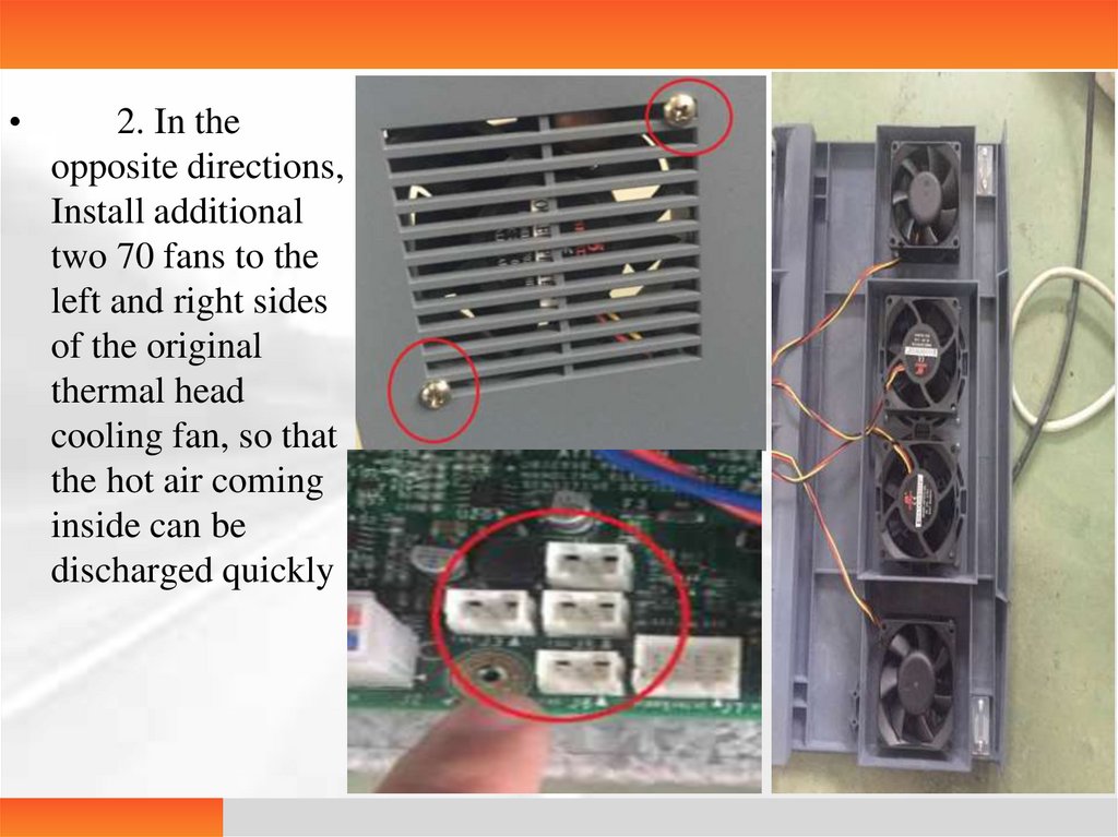
2. In the
opposite directions,
Install additional
two 70 fans to the
left and right sides
of the original
thermal head
cooling fan, so that
the hot air coming
inside can be
discharged quickly
67.
The printed film has no image• Problem: The workstation processes the image normally, but there is no
image on the printed film
• Analysis: 1. Films are put reversely
2. Counting wheel sensor problem
3. The main control panel is damaged or the 24V power problem
• Solution: 1. Check if there are still some films put reversely
2. Fix the counting wheel or re-connect the cable.
3. Check if the main control panel has a 24v input by the
multimeter; if so, the switch power is damaged; if there exists 24v input but
no 24v output, then the main control panel is damaged.
68.
69.
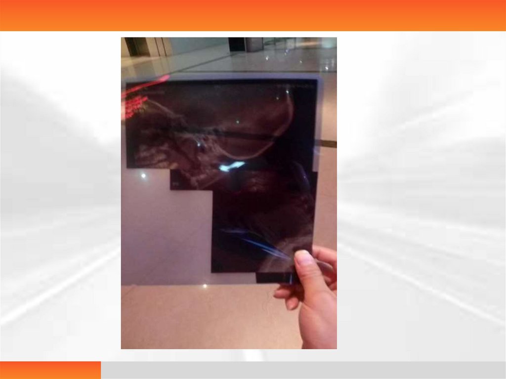
Disorderd Image• Problem: the image is upside down and cannot
be distinguished from left to right
• Analysis: The chip for processing the image on
the main control panel is damaged
• Solution: check if the original image is good
with a testing tool
• If the image is normal, replace a new main
control panel.
70.
71.
Film Size Error• Problem: After receiving the printing task, the
film size error is reported.
• Analysis: 1. The received task does not match
the actual film size
2. The Print Task Management
Interface Queue shows hot, hot, hot
• Solution: 1. Enter the Printer Task
Management Interface to delete the tasks not
in line with the film size.
2. Delete the whole app software,
and then re-install.
72.
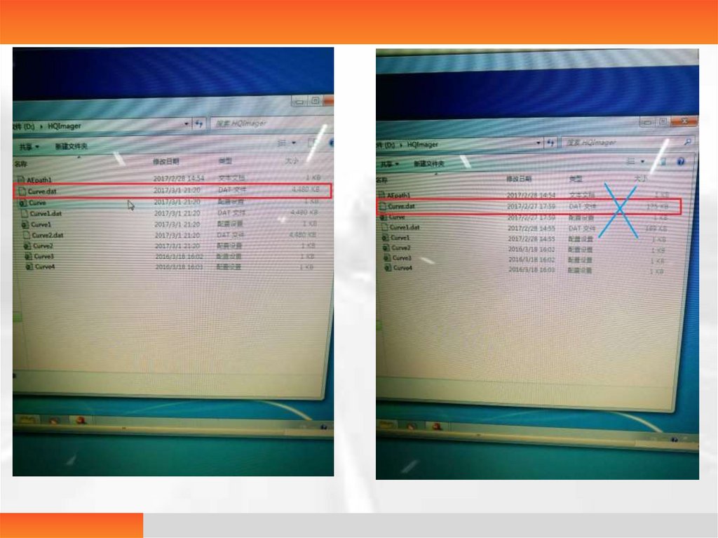
Print a blank film in normal operation• Problem: Print a blank film without any error report
• Analysis: 1. Films are put reversely
2. Curve parameters in the D:\ hqimager folder are
wrong
• Solution: 1. Check whether the gap is in the lower left corner
of the box
2. Enter the D:\hqimager to check the curve file size,
as shown below, the standard size is as follows:
4480kb for 320 model and 227328kb for 508 model;
Enter the used curves 1, 2, 3 and 4 and save the settings one
by one.
73.
74.
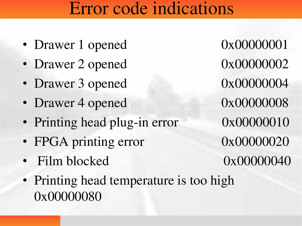
Error code indications• Drawer 1 opened
0x00000001
• Drawer 2 opened
0x00000002
• Drawer 3 opened
0x00000004
• Drawer 4 opened
0x00000008
• Printing head plug-in error
0x00000010
• FPGA printing error
0x00000020
• Film blocked
0x00000040
• Printing head temperature is too high
0x00000080
75.
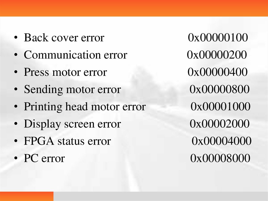
• Back cover error• Communication error
• Press motor error
• Sending motor error
• Printing head motor error
• Display screen error
• FPGA status error
• PC error
0x00000100
0x00000200
0x00000400
0x00000800
0x00001000
0x00002000
0x00004000
0x00008000
76.
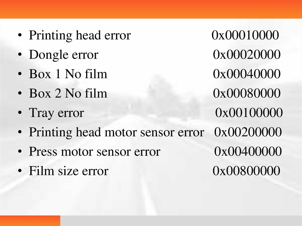
• Printing head error0x00010000
• Dongle error
0x00020000
• Box 1 No film
0x00040000
• Box 2 No film
0x00080000
• Tray error
0x00100000
• Printing head motor sensor error 0x00200000
• Press motor sensor error
0x00400000
• Film size error
0x00800000
77.
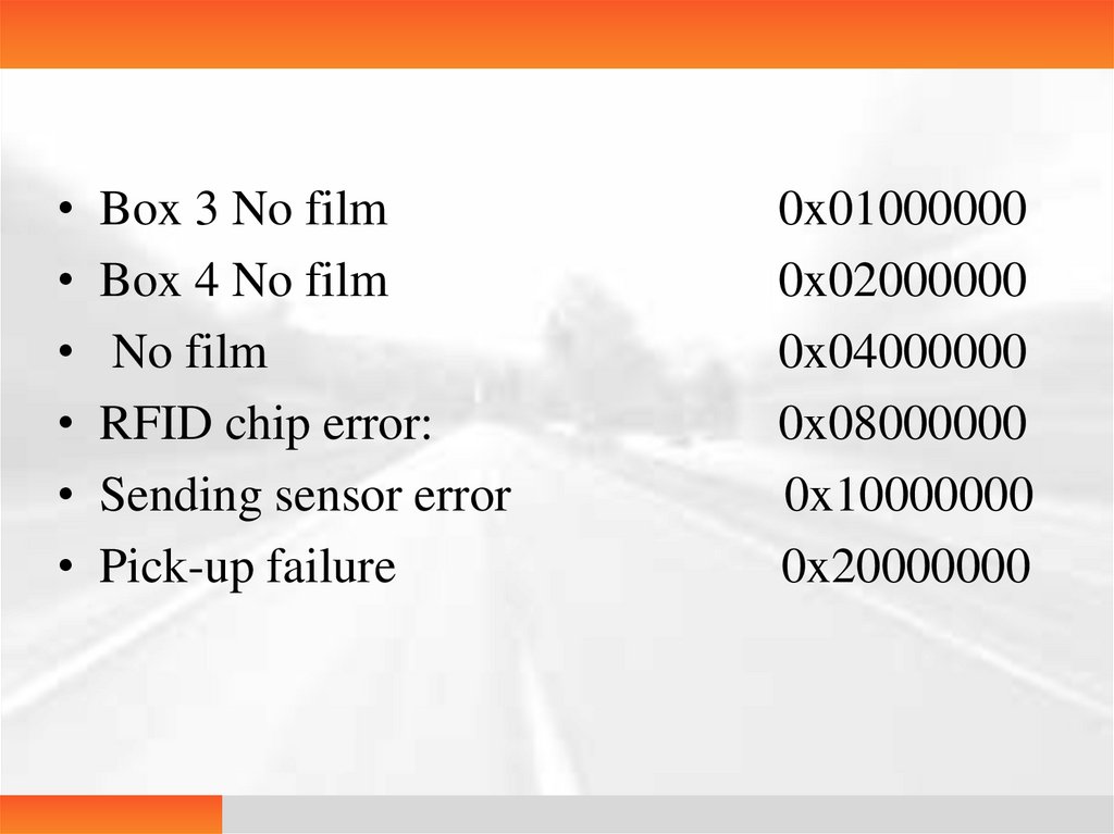
• Box 3 No film• Box 4 No film
• No film
• RFID chip error:
• Sending sensor error
• Pick-up failure
0x01000000
0x02000000
0x04000000
0x08000000
0x10000000
0x20000000
78.
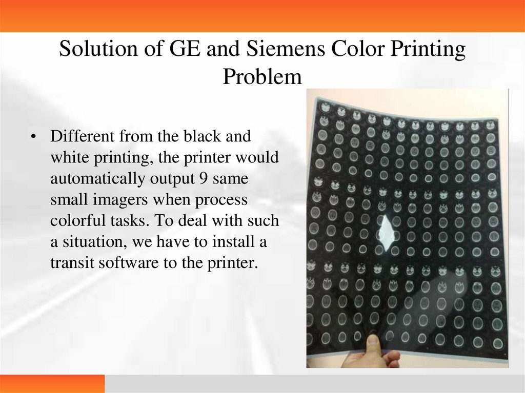
Solution of GE and Siemens Color PrintingProblem
• Different from the black and
white printing, the printer would
automatically output 9 same
small imagers when process
colorful tasks. To deal with such
a situation, we have to install a
transit software to the printer.
79.
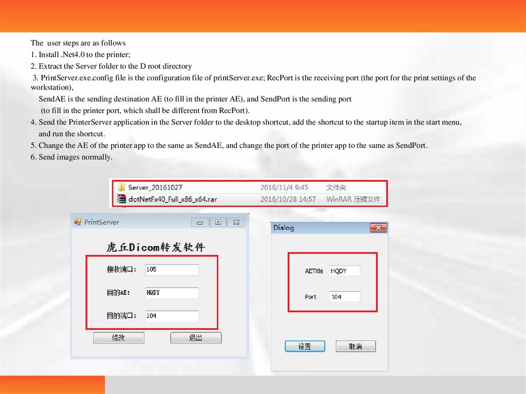
The user steps are as follows1. Install .Net4.0 to the printer;
2. Extract the Server folder to the D root directory
3. PrintServer.exe.config file is the configuration file of printServer.exe; RecPort is the receiving port (the port for the print settings of the
workstation),
SendAE is the sending destination AE (to fill in the printer AE), and SendPort is the sending port
(to fill in the printer port, which shall be different from RecPort).
4. Send the PrinterServer application in the Server folder to the desktop shortcut, add the shortcut to the startup item in the start menu,
and run the shortcut.
5. Change the AE of the printer app to the same as SendAE, and change the port of the printer app to the same as SendPort.
6. Send images normally.
80.
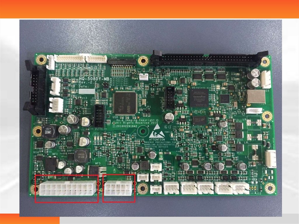
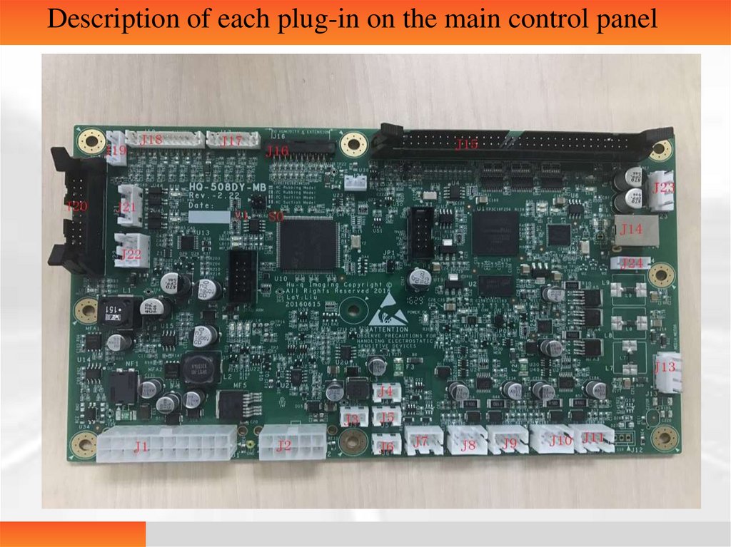
Description of each plug-in on the main control panel81.
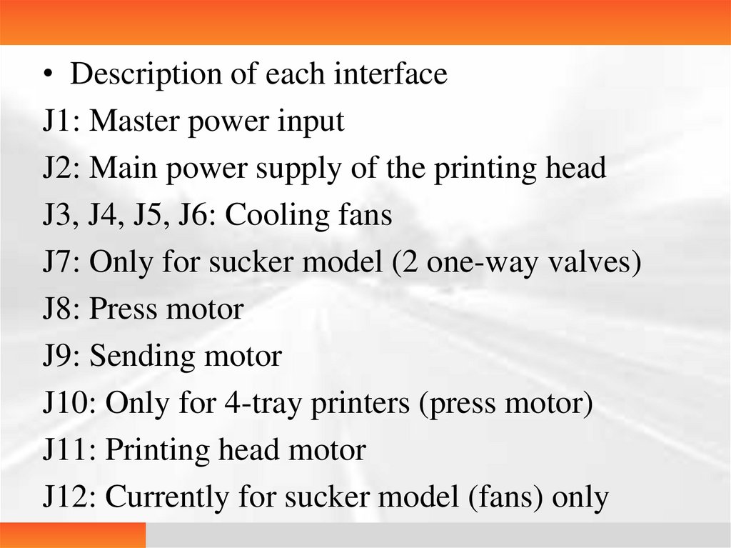
• Description of each interfaceJ1: Master power input
J2: Main power supply of the printing head
J3, J4, J5, J6: Cooling fans
J7: Only for sucker model (2 one-way valves)
J8: Press motor
J9: Sending motor
J10: Only for 4-tray printers (press motor)
J11: Printing head motor
J12: Currently for sucker model (fans) only
82.
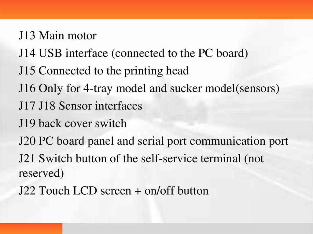
J13 Main motorJ14 USB interface (connected to the PC board)
J15 Connected to the printing head
J16 Only for 4-tray model and sucker model(sensors)
J17 J18 Sensor interfaces
J19 back cover switch
J20 PC board panel and serial port communication port
J21 Switch button of the self-service terminal (not
reserved)
J22 Touch LCD screen + on/off button
83.
J23 Power supply of the printing head (for thechip)
S0 S1 Connected for the self-service terminal;
not required for a single printer
84.
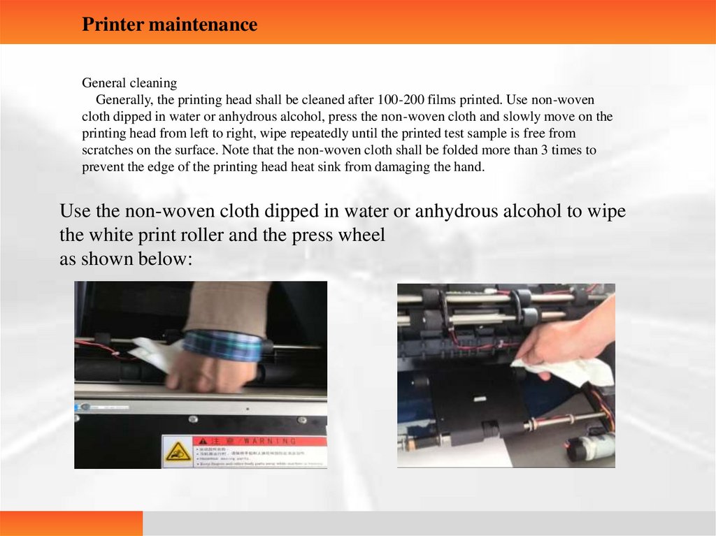
Printer maintenanceGeneral cleaning
Generally, the printing head shall be cleaned after 100-200 films printed. Use non-woven
cloth dipped in water or anhydrous alcohol, press the non-woven cloth and slowly move on the
printing head from left to right, wipe repeatedly until the printed test sample is free from
scratches on the surface. Note that the non-woven cloth shall be folded more than 3 times to
prevent the edge of the printing head heat sink from damaging the hand.
Use the non-woven cloth dipped in water or anhydrous alcohol to wipe
the white print roller and the press wheel
as shown below: