Similar presentations:
MP C3003-6003. Service master update training Ricoh Academy Europe
1.
Metis-C1D146/D147/D148/D149/D150
MP C3003SP/3503SP/4503ASP/4503SP/
5503ASP/5503SP/6003SP
Service Master Update Training
Ricoh Academy Europe
24/10/2019
Version: 1.1.a Classification: Internal Owner: Ricoh Academy Europe
1
2. Objectives
After completing this training you should be:Able to install the MP C3003 series in the field.
Able to perform routine maintenance.
Able to troubleshoot and repair the product in the field.
Familiar with the Cheetah operation panel.
To reach these objectives you must have knowledge
about the predecessor Athena-C3 and Apollon-C3.
2
3. Requirements
Metis-C1 with Cheetah operation panel.Windows PC.
Field Service Manual.
This presentation.
3
4. Pre-requisites and exam
Before starting this training you must already havefollowed the My-Ricoh training for:
Printing 2012
Basic Colour
MP C3003 series – Introduction
At the end of this course, you can do the exam on:
www.my-ricoh.com
4
5. Module overview
1. Introduction2. Installation
3. Maintenance
4. Detailed Section Descriptions
5. Troubleshooting
6. Android Operation Panel
5
6. 1. Introduction
67. Metis-C1
The Metis-C1 is the successor model of the Athena,Apollon and Diana series.
The Metis-C1 comes in 7 different speeds
(20/25/30/35/45/55 and 60 ppm) and standard with
different options like:
ARDF
SPDF
Cheetah (Smart Operation Panel)
GW2012A controller.
7
8. Different models
Model Model Name Print Speed (ppm) Standard Option Operation PanelMetis-C1a
Metis-C1b
Metis-C1c
Metis-C1d
Metis-C1e
Metis-C1y
Metis-C1z
MP C3003SP
MP C3003ZSP
MP C3503SP
MP C3503ZSP
MP C4503SP
MP C4503ASP
MP C4503ZSP
MP C4503ZASP
MP C5503SP
MP C5503ASP
MP C5503ZSP
MP C5503ZASP
MP C6003SP
MP C6003ZSP
MP C2003SP
MP C2003ZSP
MP C2503SP
MP C2503ZSP
30
30
35
35
45
45
45
45
55
55
55
55
60
60
20
20
25
25
ARDF
ARDF
ARDF
ARDF
ARDF
SPDF
ARDF
SPDF
ARDF
SPDF
ARDF
SPDF
SPDF
SPDF
ARDF
ARDF
ARDF
ARDF
Conventional
Cheetah
Conventional
Cheetah
Conventional
Conventional
Cheetah
Cheetah
Conventional
Conventional
Cheetah
Cheetah
Conventional
Cheetah
Conventional
Cheetah
Conventional
Cheetah
Conventional panel
Cheetah panel
ARDF
SPDF
8
9. Difference between the models
Fusing unit:Fusing lamps and shield is different between a/b models and
c/d/e models.
Toner cartridge:
The amount of toner inside the cartridge is different between
the a/b models and the c/d/e models.
Print speed at 1200 dpi:
Print speed is reduced to half for the a/b models.
Metis-C1 a/b
Metis-C1 c/d/e
Laser Unit
1 Laser beam
2 Laser beams
Air flow
8 fans
11 fans
Double feed detection
No
Only Metis-C1e
Bypass
side fence contact sensor
mechanism (metis-c1e
only)
9
10. Yield and consumables
Toner cartridges:Metis-C1a/b:
K: 28k prints/bottle
YMC: 18k prints/bottle
Metis-C1c/d/e:
K: 31k prints/bottle
YMC: 22.5k prints/bottle
Waste toner bottle: 100k
Replaced by customer (default)
With SP5-073-001, this can be changed to technician
replacement.
10
11. Targets & reliability
Targets & reliabilityAverage Print Volume (APV):
Metis-C1a: 5k/month
Metis-C1b: 7k/month
Metis-C1c: 10k/month
Metis-C1d: 12k/month
Metis-C1e: 15k/month
Colour ratio: 30%.
PM interval: 300k, 400k.
Machine life:
a/b models: 1200k/5 years.
c/d/e models: 3000k/5 years.
11
12. 2. Installation
1213. Important
1 of the changed items from the predecessor is the totalweight of the machines.
This is achieved by (where it is possible) replacing metal
frame by plastic frame.
So the screws which are used are:
Self tapping
Metal
The way to insert these screws is different.
The self tapping screw always turn them counter clockwise
first until you feel a click.
Self Tapping
Metal
13
14. Hardware Installation
Basically, this is very simple.Remove packing materials.
Remove the seals from the PCDUs (if applicable).
Connect the PCDU harnesses.
Rotate two levers on the ITB clockwise until they point down.
Install the toner bottles.
Toner is transported to the hopper when the machine is
switched “on” for the first time. This will take about 5 minutes.
14
15. Lifting the machine
Always lift the machine with the handles at the bottom.When shipped from the factory, these handles are
obscured by packing materials. So, remove the packing
materials before you attempt to lift the machine.
15
16. Removing the PCDU seals
Each PCDU [A] has a seal [B] that must be removedduring installation.
16
17. Front covers PCDU’s & ITB unit
Front covers PCDU’s & ITB unitCovers are not installed on the machine when it is
from the factory.
After the seal is removed from each PCDU and the
levers are down, attach the covers.
17
18. ITB levers
Two levers:Move them down for normal operation.
Move them up when you want to pull out or push in the ITB unit.
Waste toner bottle contact lever (A):
The lever must be moved so that the waste toner path from the ITB
connects to the waste toner bottle.
ITB contact lever (B):
The ITB belt is moved down to contact the black PCDU.
18
19. Toner bottles
Toner bottlesThe shape of the bottles is
different from previous
models.
You must remove a cap from
the bottle before installing it
in the machine.
19
20. ARDF
To prevent original jams when feeding thin originals theslider in the exit can be adjusted.
Normal paper
Thin paper
20
21. Boards (SPDF/ARDF)
An additional IPU board is installed on the SPDF model.The BCU board is different between the SPDF model and
the ARDF model.
Additional IPU board
IPU board
BCU board
21
22. Internal finisher
The punch unit for this finisher must be installed firstbefore you install the finisher.
When the one-bin tray is installed, install this first.
See the installation procedure for the internal finisher in the
service manual for details.
Always install the stabilizers on the base machine.
The stabilizers are included in the accessories.
22
23. Finisher SR3140 (D687)
Only for D687: Two stabilizers are included asaccessories.
They must be attached to the finisher just after it is taken out
of the shipping box.
23
24. Imageable area extension unit
You need this option for printing on 320mm width paper.During installation:
Change some SP mode settings
Install the hardware option (new paper transfer roller)
The SP mode settings are related to process control.
Real time process control must be disabled.
24
25. What can happen?
SP setting is the normal setting (SRA3 paper notsupported) and the optional longer paper transfer roller is
installed:
Images at the edges of SRA3 paper will not be transferred.
MUSIC/program control pattern adheres to the ends of the
paper transfer roller (outside the A3 area).
Real-time process control is not performed correctly.
SP setting is for SRA3 and the paper transfer roller is the
normal one (SRA3 paper not supported)
Images at the edges of SRA3 paper will not be transferred.
Real-time process control is not performed, and productivity
will decrease.
The waiting time for fusing temperature rise is longer than
intended.
25
26. Enter SP Mode
The number sequence to enter SP mode is changed.1
0
7
8
0
6
1
8
2
26
27. SD Card Slots
[A]: SD card slot 1 (option slot)[B]: SD card slot 2 (service slot)
D146/D147
D148/D149/D150
27
28. SD Card Merging
In former models there are some SD card options thatcan’t be merged.
In Metis-C1, there are no restrictions.
For example, the part of the Postscript software that requires
licensing is now built into the controller, so the portion on the
SD card can be moved to another SD card.
You can insert SD card options in any slot on controller
board.
Recommend that you insert SD card options in slot 1,
because slot 2 is also used as the service slot.
28
29. Embedded OCR (Searchable PDF)
Do the installation procedure according to the field servicemanual.
SP 5-878-004 must be done twice:
First time is to link the SD card to the machine.
Second time is to copy the dictionary data to the machine.
After installation:
Remove the SD card from the SD slot.
Save the SD card in the storage space under the switch
cover (A).
Machine
NVRAM
SD
OCR
Serial number
29
30. After Installing the Machine and All Options
After you have finished installing the machine, back up theNVRAM to an SD card. Also, do this after every service
visit.
30
31. 3. Maintenance
3132. PM Parts
PCDUPCU-K: 400k
Development Unit – K: 600k
Transfer
ITB Unit: 600k
ITB Cleaning Unit: 300K
PTR Unit: 400k
Fusing
Pressure Roller: 400k
Heating Sleeve Unit: 400k
Ball Bearing: 400k
Other
Waste Toner Bottle: 100k (this is replaced by the customer, but can be
changed to technician PM replacement by SP 5-073-001)
Exhaust Filters: 300k
32
33. Yield Parts
Development Unit – CMY: 600kPCU – CMY: 270k
ARDF Feed Belt, Pick-up Roller, Reverse Roller: 120k
originals
33
34. Replacing a PM Part
1. Execute the SP for forced detection of a new part.2.
3.
4.
5.
See the next slide for a list of SP modes for each part.
Turn the power off
Replace the part.
Turn the power on.
The machine automatically resets the counter,
replacement day, remaining number of days, and
executes the necessary automatic adjustments for the
new part.
Do not use the PM counter clear SP mode.
34
35. SP Modes before PM part replacement
SP3-701-002 PCU BkSP3-701-003 Dev Bk
SP3-701-025 PCU C
SP3-701-026 Dev C
SP3-701-048 PCU M
SP3-701-049 Dev M
SP3-701-071 PCU Y
SP3-701-072 Dev Y
SP3-701-093 ITB Unit
SP3-701-102 ITB Cleaning
SP3-701-109 PTR
SP3-701-118 Pressure Roller
SP3-701-131 Ozone filter
SP3-701-132 Exhaust filter
SP3-701-206 ADF pick up roller
SP3-701-207 ADF feed
SP3-701-208 ADF reverse
35
36. New Function: PM Counter
New features on the PM counter display allow you to seethe following:
Estimated usage rate / Remaining days (with relation to PM
yield)
Commissioning Status Report
36
37. New Function: PM Counter
For some machines this function was already available.SP Mode initial screen
37
38. PM counter
By pressing the PM Counter button, you go into the PMParts menu of the SP Mode.
38
39. All PM parts list
3940. Counter clear for parts exceeding target yield
4041. Parts list for PM yield indicator
4142. Clear all PM settings
4243. Parts exceeding target yield
4344. Counter list print out
4445. Estimated Usage Rate/Remain Days
4546. Commissioning Status Report Print
4647. Page counter and Running distance
Running DistanceA
B
C
You should
replace the
part when the
running
distance
reaches 100%
PM Counter
47
48. Page Counter and Running Distance
PM parts yield is based on the page counter when thecustomer prints using the target conditions.
But, for most PM parts, the yield depends on running
distance
See the formula below for how this is calculated.
So, a function was added to display the estimated PM
yield, in which the running distance is included.
Running Distance (m) (SP7-944-001~127)
= Motor rotation time (s) × Paper speed (mm/s)/1000
48
49. Estimated Value Display
4950. Estimated Usage Rate Display
Displays the larger of these two values: Page counter (SP7954-xxx) and running distance (SP7-942-xxx).Note that parts such as rollers are displayed using the page
counter value since running distance is not measured.
Estimated usage rate % by page counter = A/B*100
A: Current page counter value (SP7-621-xxx)
B: Standard page end value (SP7-623-xxx)
Estimated usage rate % by running distance = A/B*100
A: Current distance value (SP7-944-xxx)
B: Standard distance end value (SP7-940-xxx)
50
51. Estimated Remaining Days Display
Displays the smaller of these two values: Page counter (SP7951-XXX) and running distance (SP7-952-XXX).Again, note that parts such as rollers are displayed using the
page counter value since running distance is not measured.
Remaining days by page counter (SP7-951-XXX) = (A – B) / C
A: Standard end value by pages (SP7-623-xxx)
B: PM page counter (SP7-621-xxx)
C: Average PM page counter per day = PM page counter (SP7621-xxx)/Number
of days since last replacement
Remaining days by running distance (SP7-952-XXX) = (A – B) / C
A: Standard end value by distance (SP7-940-xxx)
B: PM distance counter (SP7-944-xxx)
C: Average distance per day = PM distance counter (SP7-944-xxx) /Number of
days since last replacement
51
52. Commissioning Status Report
You can print the Status Report to check the machine status.1.
2.
3.
4.
5.
6.
7.
SP7-403-001~010
SP7-507-001~010
SP7-508-001~010
SP7-910-001, 002
SP7-911-001, 002
SP8-581-001
SP8-591-001
SC History
Printer Engine Jam History
Original Jam History
ROM No
Firmware version
T: Counter
O: Counter
52
53. 4. Detailed Section Descriptions
5354. Chapter Overview
4.1 Machine Overview4.2 Scanner
4.3 Laser Unit
4.4 PCDU
4.5 Toner Supply
4.6 Image Transfer
4.7 Fusing
4.8 Paper Exit, Duplex
4.9 Waste Toner Collection
54
55. 4.1 Machine Overview
5556. Components
Athena & Apollon-C356
57. Drive Components
Athena & Apollon-C357
58. Differences from Predecessors: Drive
Metis-C1Predecessor
Purpose
1
Individual motors for paper feed and
transport (DC motors)
One motor for paper
feed and transport
(stepper motor), with
clutch
Energy saving, higher
productivity and less
noise
2
Individual motors for paper exit and
fusing drive.
One motor for fusing
and exit.
Different layout
58
59. Drive Components
Paper Exit/Pressure Release MotorFusing Motor
PCU Motor: CMY
Development Motor: CMY
Paper Transfer Contact Motor
Development Motor: Black
Transport Motor
Paper Feed Motor
PCU: Black/ Image Transfer Motor
Registration Motor
59
60. Paper Path (1/3)
Athena & Apollon-C360
61. Paper Path (2/3)
Internal Finishernot available.
Athena & Apollon-C3
61
62. Paper Path (3/3)
6263. Cooling Metis-C1 a/b
8 Fan’s are used for cooling.Front
Rear
PCBs
63
64. Cooling Metis-C1 c/d/e
11 Fan’s are used for cooling.Front
Rear
PCBs
64
65. Function of fans
Call-outFan
Intake/Exhaust
Model
1
Development air intake fan / right
Intake
ab, cde
2
Development air intake fan / left
Intake
ab, cde
3
Paper discharge cooling fan
Exhaust
ab, cde
4
Fusing heat discharge fan
Exhaust
ab, cde
5
Odor filter
Exhaust
ab, cde
6
Ozone exhaust fan
Exhaust
ab, cde
7
Drive cooling fan
Intake
cde
8
Toner supply cooling fan
Intake
ab, cde
9
Main body exhaust fan
Exhaust
cde
10
Ozone filter/Dust filter
Exhaust
ab, cde
11
Electric box cooling fan
Intake/Exhaust
ab, cde
12
PSU heat discharge fan
Exhaust
cde
13
PSU cooling fan
Intake
ab, cde
65
66. Cooling Notes
Toner supply cooling duct: The shape of the duct for MetC1c/d/e is different from Met-C1a/b.Paper is cooled immediately after fusing to reduce:
the temperature of the stack
curling
condensation in the paper exit area.
During output, the operation of fans depends on the
machine’s internal temperature.
This temperature is measured by a temperature/humidity
sensor at the rear of the PCDUs.
After output, the fans stay on until the machine cools
enough.
66
67. Differences from Predecessors: Electrical Components
Metis-C1Predecessor
Operation Panel
Two types of LCD (not
compatible with each
other)
One type of LCD
IOB
Two IOBs for image
creation and paper
transfer
One IOB
NVRAM
Two NVRAM’s
One
FFC
1. FFC used for main
signal line
2. 2 piece connection
1. Wire harness
2. Only flat cable
Main Switch
1. DC SW
2. Press and hold =
forced power off
1. Rocker SW
2. The plug must be
pulled out to force
power off.
Fax
Bracket added to the
replacement FCU part
No bracket for the FCU
Purpose
Optimized layout
1. Weight reduction
2. Easier to handle
Easier to handle
67
68. Locations of PCBs Inside the Controller Box
A.B.
C.
D.
E.
F.
G.
IPU Sub (only if an SPDF is present)
IPU
BCU
Controller Box Cooling Fan
CPU Cooling Fan
Controller Board
HDD
68
69. Locations of PCBs Behind the Controller Box
A. HVP_TTSB. Imaging IOB
69
70. Locations of PCBs Inside the Power Box
A. PSU (AC controller board)B. PSU (DC Power)
C. PSU Cooling Fan
70
71. Locations of PCBs Behind the Power Box
A. HVP_CBB. Paper Transport IOB
71
72. Differences from Predecessors: Servicing
Metis-C1Predecessor
Procedure at electrical
board replacement
Must always hold the main switch
down before starting a procedure for
electrical board replacement (in
order to remove residual charge)
No procedure
Grease used in the fusing
unit
Grease for use with metal
(Fluotraibo) on pressure roller and
bushing.
Traditional grease (Barierta)
Release for Fusing high
temperature detection
Fusing unit replacement is required
only for SC544/554.
Fusing unit replacement is
required for
SC544/554/564/574.
Imageable area extension
option
VM function on the
controller board
SP setting is required at the
installation (25 Sps now, will be
changed to 1 SP).
The PM yield is the same as the
normal PTR. Regular PM
replacement is required.
VM is built into the controller board.
Accordingly, the procedure to
update VM firmware is changed.
VM function is provided as an
SD card option.
72
73. Switch off procedure
Push the power switch [A] on the machine.Wait until the shut-off screen disappears.
Take out the power cord.
Push the power switch [A] again to remove the residual
charge.
Note: If some LEDs on any of the boards are blinking or lit,
current is still present.
73
74. Starting the machine again
To start the machine, press the main power switch.If you press the main power switch during the shutdown
procedure, the machine will not start.
74
75. Forced Shutdown
In case normal shutdown does not complete, the machinehas a forced shutdown function.
To make a forced shutdown, press and hold the main
power switch for 6 seconds.
In general, do not use the forced shutdown.
Forced shutdown may damage the hard disk and memory,
and can cause damage to the machine.
Use a forced shutdown only if it is unavoidable.
75
76. Replacement of parts
Some of the covers have tabs on them which break easily.The procedures in the service manual have diagrams to
show where the tabs are.
Take care not to break them when handling the covers.
For example:
Upper Left Cover
76
77. LCD Panel (1/2)
LCD panels from two different vendors are used.Depending on which type is used in the machine:
The bracket for attaching the panel has a different shape.
The exterior cover on the machine has a different shape.
So, if you replace the LCD panel, make sure that you
install the correct type.
77
78. LCD Panel (2/2)
How to determine the correct type to install?There are three labels on the rear of the operation panel.
The center label [A] shows the LCD model number.
The first letter is either an S or a C, to indicate the
different vendors.
If your machine has a label starting with S, you can only
replace the LCD with one that has a label starting with S.
If your machine has a label starting with C, you can only
replace the LCD with one that has a label starting with C.
78
79. Replacing NVRAMs on the Controller Board
Make sure that theNVRAMs are installed in
the correct sockets.
2M-1 must be in FRAM1
next to it.
2M-2 must be in FRAM2
next to it.
79
80. 4.2 Scanner
8081. Differences from Predecessors: Scanner unit
Metis-C1Predecessor
Purpose
1
LED Scanning on all models
45/55 CPM halogen scan
Energy saving
2
Non contact sheet-through scan
(DF use)
Contact sheet-through scan
Reduction of black line
occurrence
81
82. Scanner Unit
8283. DF exposure glass
Originals may cause streaks on the exposure glass.To prevent these streaks non-contact scan is done.
The ADF exposure glass has a mylar, which guides the
original over the glass.
Mylar
No contact
Contact
83
84. Dust Detection – Overview
This function checks the ADF exposure glass for dust thatcan cause black lines in copies.
The dust check is done before the first original is scanned.
This is done only once at the beginning of a job.
The check is not done for originals added during a long
scanning job.
If dust is detected, a message is displayed on the
operation panel, but the machine does not stop.
84
85. Dust Detection (SP 4-020)
SP 4-020-001: Enable/disable (default – disabled)SP 4-020-002: Sensitivity adjustment
SP 4-020-003: Do not adjust in the field
SP 7-852: Counts how many times the machine detected dust
on the ADF.
85
86. Dust Detection - Action Taken
When dust detection determines that dust exists, the scanpoint shifts in order to avoid the dust.
There are three scanning points.
a: Home position
b: The first time that dust is detected, the scanner moves here.
c: The next time that dust is detected, the scanner moves here.
If dust is detected again, the scanner moves back to a. Then with
consecutive dust detections, the scanning position cycles a > b
> c > a > b > c , etc.
86
87. Laser Unit
8788. Differences from Predecessors: Laser unit
Metis-C1Adjustment after laser unit
replacement
1
Download the SP values
from the unit
One SP for coarse and
fine MUSIC adjustment
Predecessor
Purpose
Adjustment after laser unit
replacement
Input values into SP
mode by hand by referring
to a sheet included with
the unit.
Easier to service
Two SPs for coarse and
fine MUSIC adjustment
88
89. Overview
8990. Components
There are two LD drive boards.M150, M149, M148: 2 beams/colour
M147, M146: 1 beam/colour
90
91. Skew Adjustment
The 2nd mirrors for C, M, and Y have a motor to adjust theangle of the mirror to align the scan lines with black.
91
92. Replacing the Laser Unit
After installing the new unit:Disconnect the skew correction motor harness.
Execute SP modes as explained in the service manual to
download the correction values from the new laser unit.
It is not necessary to execute color registration after
replacing the laser unit.
92
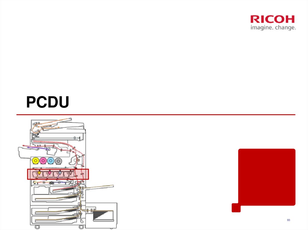
93. PCDU
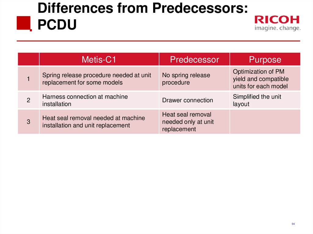
9394. Differences from Predecessors: PCDU
Metis-C1Predecessor
Purpose
1
Spring release procedure needed at unit
replacement for some models
No spring release
procedure
Optimization of PM
yield and compatible
units for each model
2
Harness connection at machine
installation
Drawer connection
Simplified the unit
layout
3
Heat seal removal needed at machine
installation and unit replacement
Heat seal removal
needed only at unit
replacement
94
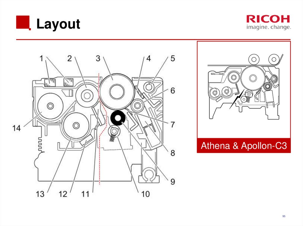
95. Layout
Athena & Apollon-C395
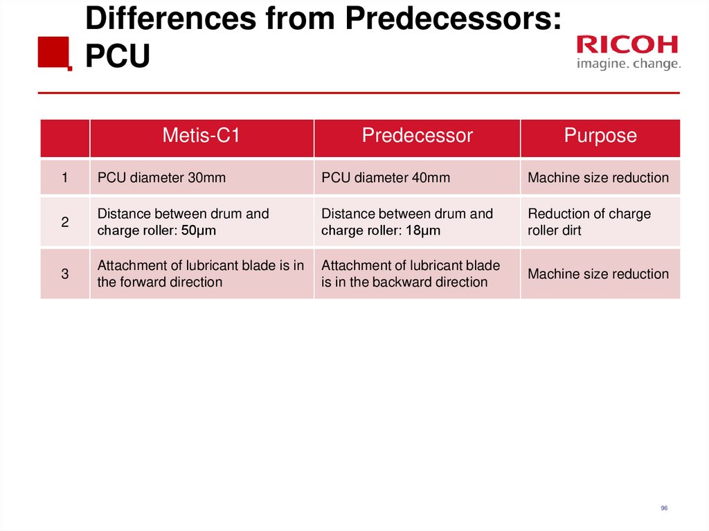
96. Differences from Predecessors: PCU
Metis-C1Predecessor
Purpose
1
PCU diameter 30mm
PCU diameter 40mm
Machine size reduction
2
Distance between drum and
charge roller: 50μm
Distance between drum and
charge roller: 18μm
Reduction of charge
roller dirt
3
Attachment of lubricant blade is in
the forward direction
Attachment of lubricant blade
is in the backward direction
Machine size reduction
96
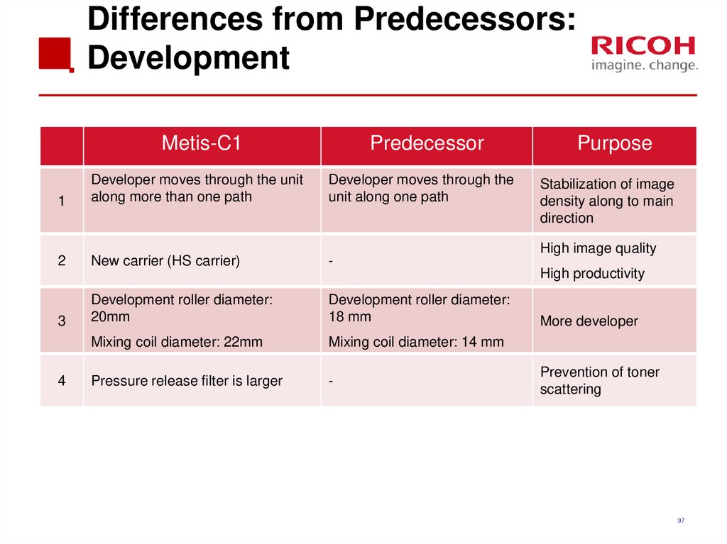
97. Differences from Predecessors: Development
Metis-C1Predecessor
1
Developer moves through the unit
along more than one path
Developer moves through the
unit along one path
2
New carrier (HS carrier)
-
3
Development roller diameter:
20mm
Development roller diameter:
18 mm
Mixing coil diameter: 22mm
Mixing coil diameter: 14 mm
Pressure release filter is larger
-
4
Purpose
Stabilization of image
density along to main
direction
High image quality
High productivity
More developer
Prevention of toner
scattering
97
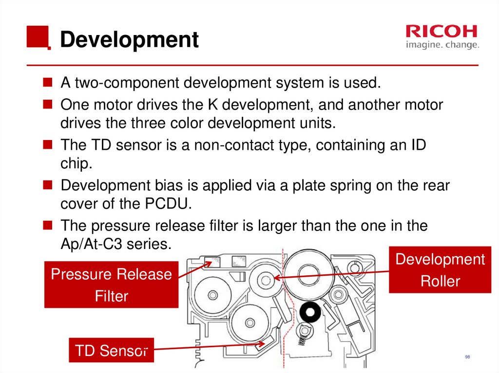
98. Development
A two-component development system is used.One motor drives the K development, and another motor
drives the three color development units.
The TD sensor is a non-contact type, containing an ID
chip.
Development bias is applied via a plate spring on the rear
cover of the PCDU.
The pressure release filter is larger than the one in the
Ap/At-C3 series.
Development
Pressure Release
Roller
Filter
TD Sensor
98
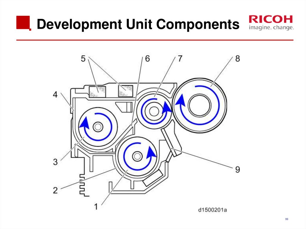
99. Development Unit Components
99100. Replacing Note for PCDU or PCU
Before replacing a PCU or PCDU, set SP3-701 to "1" forthe PCU that you will replace, and again (if you are
replacing a PCDU) for the development unit that you will
replace. Then switch the power OFF.
If you forget this procedure, the counter of the PCU will be
overwritten with the development unit value.
DO NOT exchange a PCDU or PCU unit between field
machines. (The counters will be overwritten.)
100
101. Replacement (1/3)
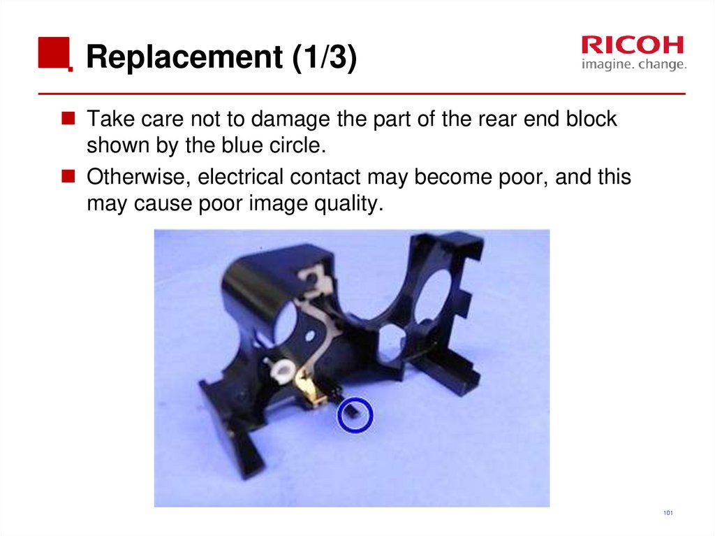
Take care not to damage the part of the rear end blockshown by the blue circle.
Otherwise, electrical contact may become poor, and this
may cause poor image quality.
101
102. Replacement (2/3)
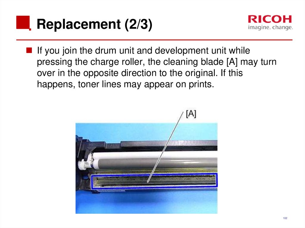
If you join the drum unit and development unit whilepressing the charge roller, the cleaning blade [A] may turn
over in the opposite direction to the original. If this
happens, toner lines may appear on prints.
102
103. Replacement (3/3)
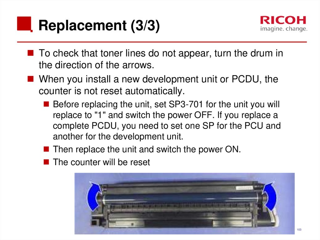
To check that toner lines do not appear, turn the drum inthe direction of the arrows.
When you install a new development unit or PCDU, the
counter is not reset automatically.
Before replacing the unit, set SP3-701 for the unit you will
replace to "1" and switch the power OFF. If you replace a
complete PCDU, you need to set one SP for the PCU and
another for the development unit.
Then replace the unit and switch the power ON.
The counter will be reset
103
104. Replacing the PCDU / PCU on a D149 or D150
An additional procedure is required when replacing thePCDU or PCU (drum unit) on the D149 and D150.
This is not necessary for the D146, D147, or D148.
During this procedure, spring pressure is adjusted. If this
is not done, the lubricant bar is consumed more quickly,
and the life of the PCDU will be reduced.
The procedure is printed on a sheet that comes with the
PCDU.
The main points are shown on the next slide.
104
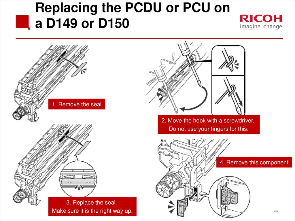
105. Replacing the PCDU or PCU on a D149 or D150
1. Remove the seal2. Move the hook with a screwdriver.
Do not use your fingers for this.
4. Remove this component
3. Replace the seal.
Make sure it is the right way up.
105
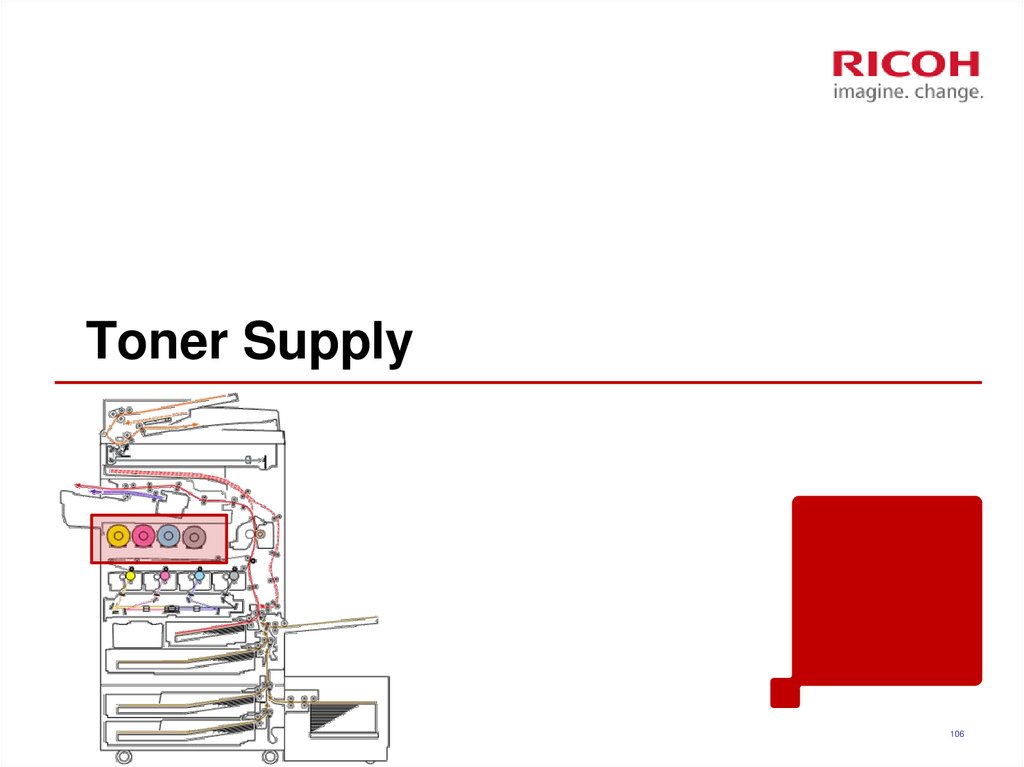
106. Toner Supply
106107. Differences from Predecessors: Toner Supply
Metis-C11
2
Hi-ACT system
Sub hopper toner supply system
Two types of toner near end
(estimated near end and definite
near end)
Predecessor
Rotary toner bottle + toner
pump
Purpose
Less machine down
time for toner bottle
replacement
One type of toner near end
107
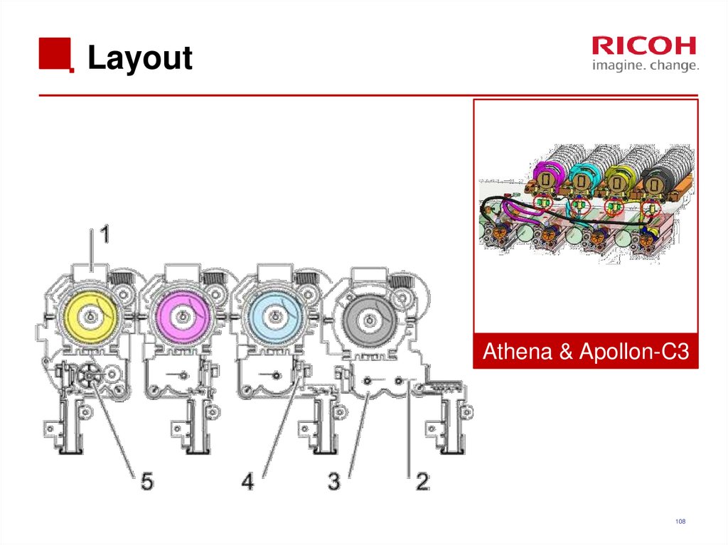
108. Layout
Athena & Apollon-C3108
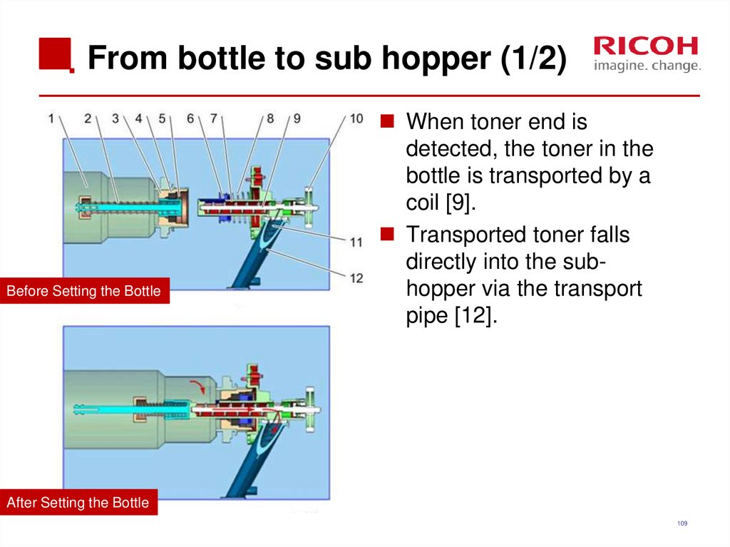
109. From bottle to sub hopper (1/2)
Before Setting the BottleWhen toner end is
detected, the toner in the
bottle is transported by a
coil [9].
Transported toner falls
directly into the subhopper via the transport
pipe [12].
After Setting the Bottle
109
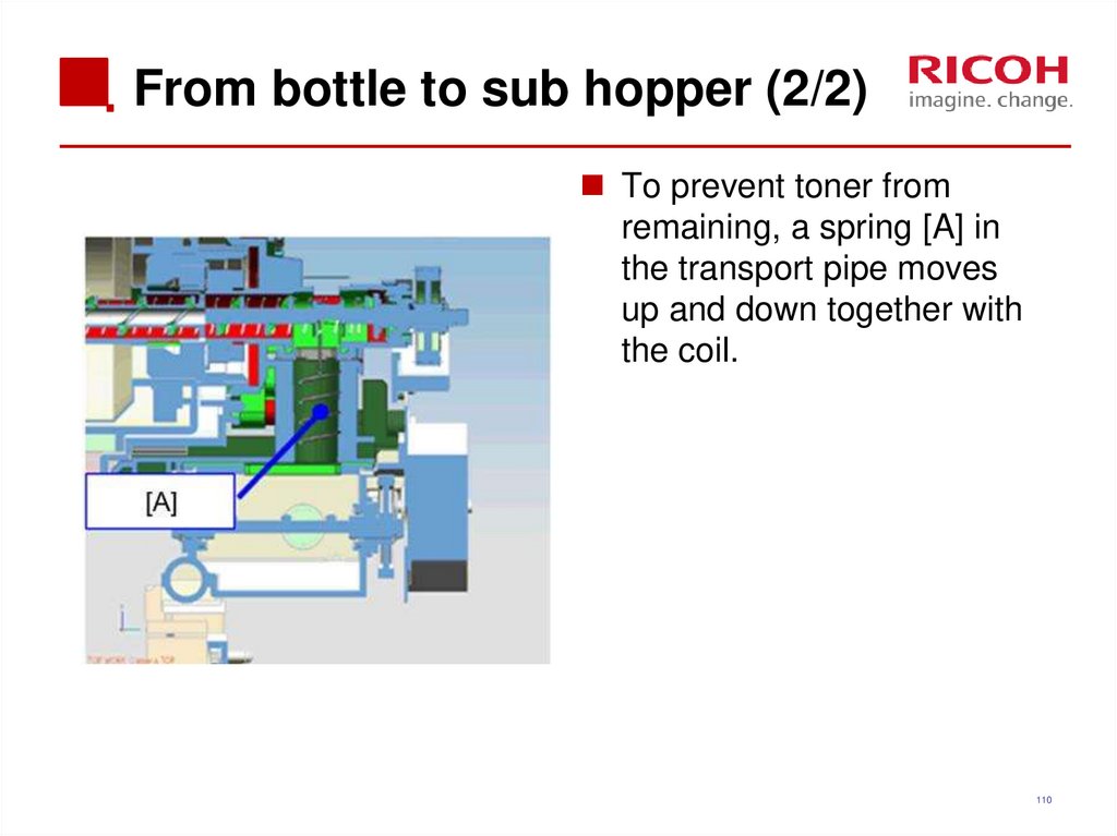
110. From bottle to sub hopper (2/2)
To prevent toner fromremaining, a spring [A] in
the transport pipe moves
up and down together with
the coil.
110
111. Toner Near-end Detection
The machine estimates the amount of toner remaining inthe cartridge using two methods, and takes the smaller
result of the two.
Toner supply motor drive time (SP3-102-001 to 004)
Pixel count (SP3-102-011 to 014)
The smaller of the two values is the amount of remaining
toner, and is stored in SP3-102-021 to 024.
Based on these measurements, the machine detects
toner near-end in two stages.
Estimated toner near-end
Definite toner near-end
111
112. ‘Estimated Toner Near-end’
If the amount of remaining toner falls below a certain limit(SP3-110-001 to 004; default 65g), the machine enters the
‘estimated toner near-end’ state.
112
113. ‘Definite Toner Near-end’
If the amount of remaining toner falls below a certain limit(SP3-120-001 to 004; default 50g), the machine then
starts to look for the ‘definite toner near-end’ condition, as
explained on the next slide.
113
114. Definite Toner Near-end detection
The machine checks the toner end sensor every 200 mswhile the development motor is on.
The result is stored in the “no toner counter” (SP3-121001 to 004).
If toner is detected, the counter is cleared.
If the no toner counter exceeds a threshold value (SP3122-001 to 004), the machine rotates the toner bottle for a
certain time (SP3-163-001), to make sure the bottle is
empty. Then, the machine checks if toner is present or not
using the toner end sensor.
If no toner is detected, the machine signals definite toner
near-end.
114
115. Toner End Detection
After toner near-end is detected, the machine signalstoner end if one of the following occurs.
Sheet count after near-end exceeds a certain threshold
Black: 221 pages
Color: 225 pages
Sheet count and pixel count after near-end both exceed a
certain threshold
The output of the toner density sensor has deviated from the
target by more than a certain threshold
115
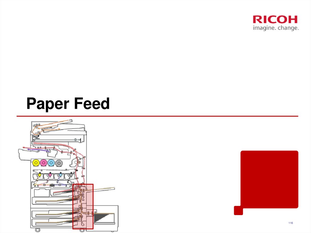
116. Paper Feed
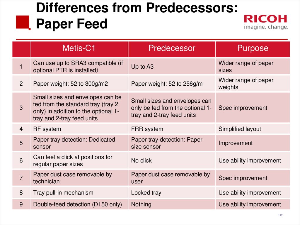
116117. Differences from Predecessors: Paper Feed
Metis-C1Predecessor
Purpose
1
Can use up to SRA3 compatible (if
optional PTR is installed
Up to A3
Wider range of paper
sizes
2
Paper weight: 52 to 300g/m2
Paper weight: 52 to 256g/m
Wider range of paper
weights
3
Small sizes and envelopes can be
fed from the standard tray (tray 2
only) in addition to the optional 1tray and 2-tray feed units
Small sizes and envelopes can
only be fed from the optional 1tray and 2-tray feed units
Spec improvement
4
RF system
FRR system
Simplified layout
5
Paper tray detection: Dedicated
sensor
Paper tray detection: Paper
size sensor
Improvement
6
Can feel a click at positions for
regular paper sizes
No click
Use ability improvement
7
Paper dust case removable by
technician
Paper dust case removable by
user
Spec improvement
8
Tray pull-in mechanism
Locked tray
Use ability improvement
9
Double-feed detection (D150 only)
Nothing
Use ability improvement
117
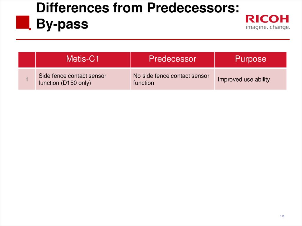
118. Differences from Predecessors: By-pass
Metis-C11
Side fence contact sensor
function (D150 only)
Predecessor
No side fence contact sensor
function
Purpose
Improved use ability
118
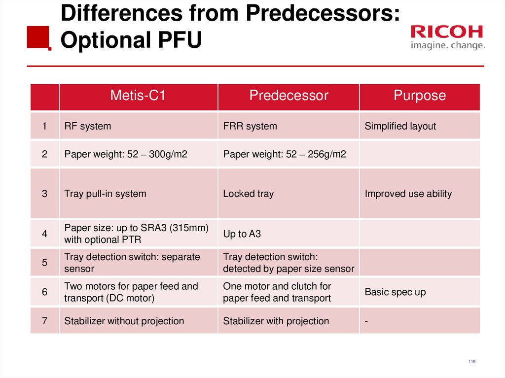
119. Differences from Predecessors: Optional PFU
Metis-C1Predecessor
Purpose
1
RF system
FRR system
Simplified layout
2
Paper weight: 52 – 300g/m2
Paper weight: 52 – 256g/m2
3
Tray pull-in system
Locked tray
4
Paper size: up to SRA3 (315mm)
with optional PTR
Up to A3
5
Tray detection switch: separate
sensor
Tray detection switch:
detected by paper size sensor
6
Two motors for paper feed and
transport (DC motor)
One motor and clutch for
paper feed and transport
Basic spec up
7
Stabilizer without projection
Stabilizer with projection
-
Improved use ability
119
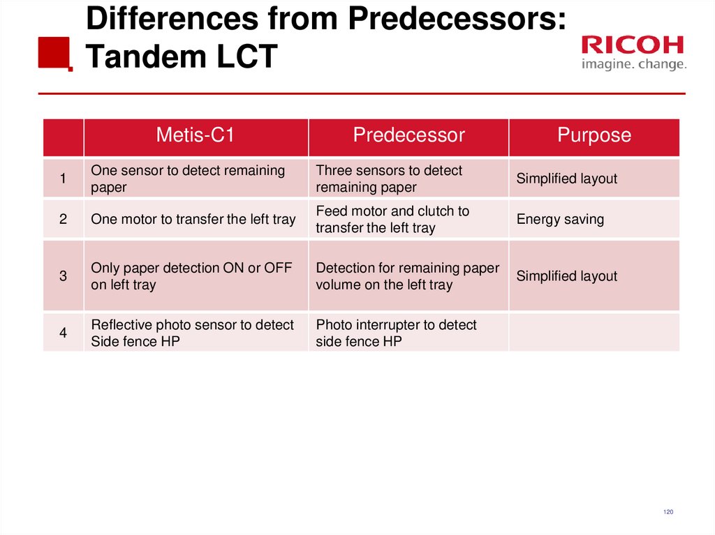
120. Differences from Predecessors: Tandem LCT
Metis-C1Predecessor
Purpose
1
One sensor to detect remaining
paper
Three sensors to detect
remaining paper
Simplified layout
2
One motor to transfer the left tray
Feed motor and clutch to
transfer the left tray
Energy saving
3
Only paper detection ON or OFF
on left tray
Detection for remaining paper
volume on the left tray
Simplified layout
4
Reflective photo sensor to detect
Side fence HP
Photo interrupter to detect
side fence HP
120
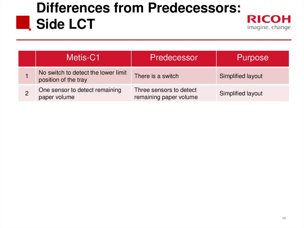
121. Differences from Predecessors: Side LCT
Metis-C1Predecessor
Purpose
1
No switch to detect the lower limit
position of the tray
There is a switch
Simplified layout
2
One sensor to detect remaining
paper volume
Three sensors to detect
remaining paper volume
Simplified layout
121
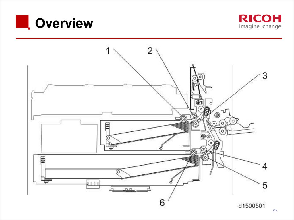
122. Overview
122123. Drive (1)
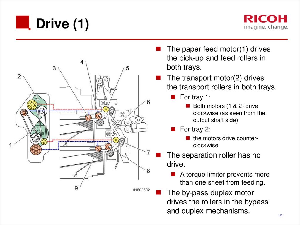
The paper feed motor(1) drivesthe pick-up and feed rollers in
both trays.
The transport motor(2) drives
the transport rollers in both trays.
For tray 1:
Both motors (1 & 2) drive
clockwise (as seen from the
output shaft side)
For tray 2:
the motors drive counterclockwise
The separation roller has no
drive.
A torque limiter prevents more
than one sheet from feeding.
The by-pass duplex motor
drives the rollers in the bypass
and duplex mechanisms.
123
124. Bottom Plate Lift
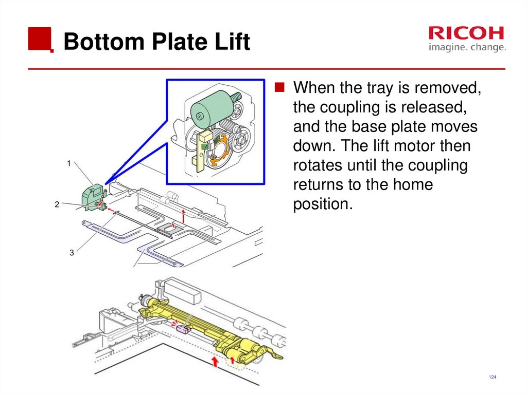
When the tray is removed,the coupling is released,
and the base plate moves
down. The lift motor then
rotates until the coupling
returns to the home
position.
124
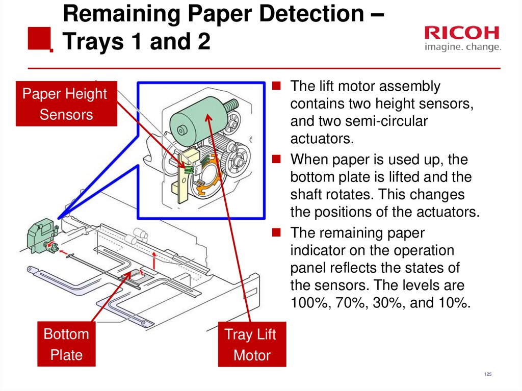
125. Remaining Paper Detection – Trays 1 and 2
Paper HeightSensors
Bottom
Plate
The lift motor assembly
contains two height sensors,
and two semi-circular
actuators.
When paper is used up, the
bottom plate is lifted and the
shaft rotates. This changes
the positions of the actuators.
The remaining paper
indicator on the operation
panel reflects the states of
the sensors. The levels are
100%, 70%, 30%, and 10%.
Tray Lift
Motor
125
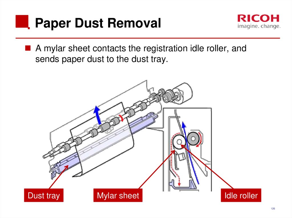
126. Paper Dust Removal
A mylar sheet contacts the registration idle roller, andsends paper dust to the dust tray.
Dust tray
Mylar sheet
Idle roller
126
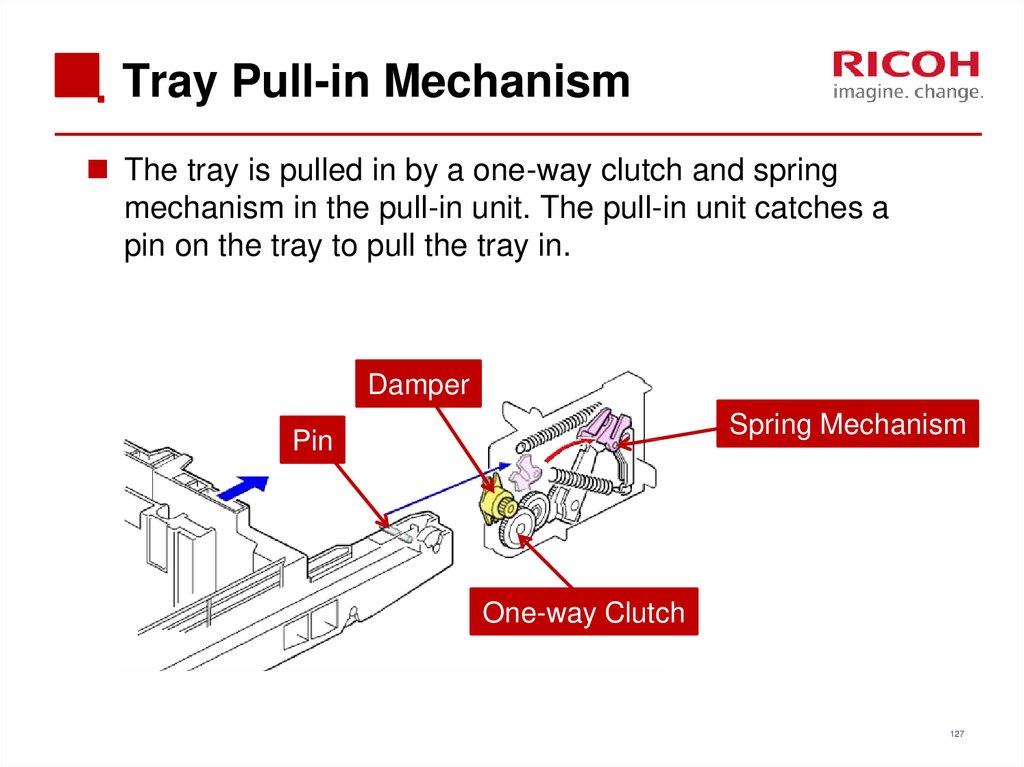
127. Tray Pull-in Mechanism
The tray is pulled in by a one-way clutch and springmechanism in the pull-in unit. The pull-in unit catches a
pin on the tray to pull the tray in.
Damper
Spring Mechanism
Pin
One-way Clutch
127
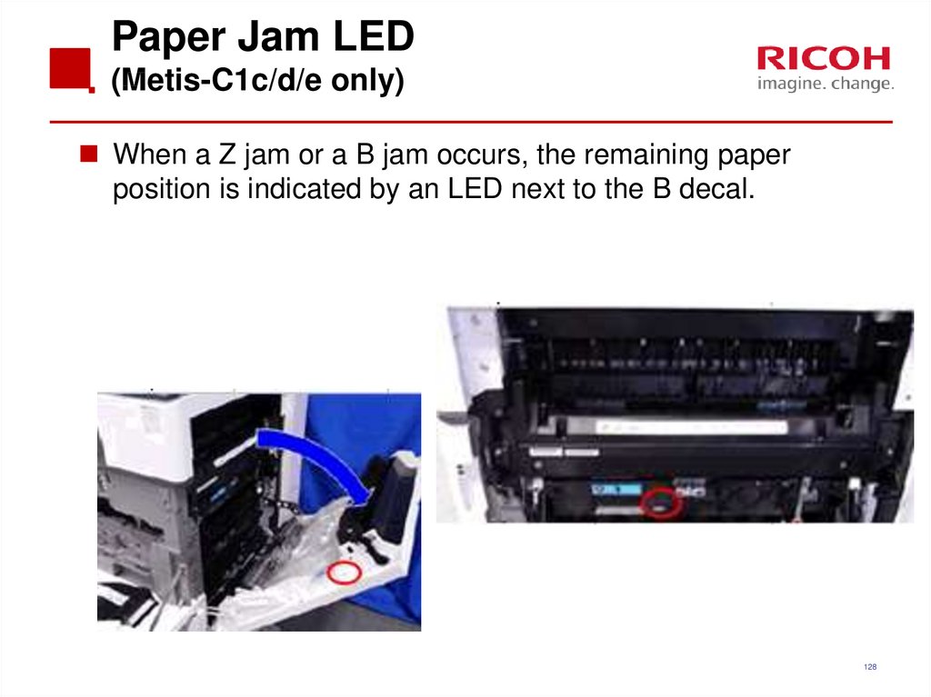
128. Paper Jam LED (Metis-C1c/d/e only)
When a Z jam or a B jam occurs, the remaining paperposition is indicated by an LED next to the B decal.
128
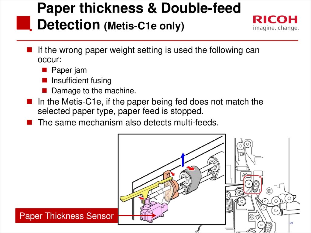
129. Paper thickness & Double-feed Detection (Metis-C1e only)
Paper thickness & Double-feedDetection (Metis-C1e only)
If the wrong paper weight setting is used the following can
occur:
Paper jam
Insufficient fusing
Damage to the machine.
In the Metis-C1e, if the paper being fed does not match the
selected paper type, paper feed is stopped.
The same mechanism also detects multi-feeds.
Paper Thickness Sensor
129
130. Principle
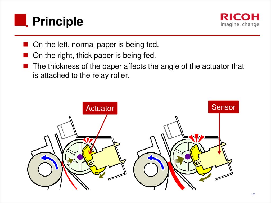
On the left, normal paper is being fed.On the right, thick paper is being fed.
The thickness of the paper affects the angle of the actuator that
is attached to the relay roller.
Actuator
Sensor
130
131. Inside Paper Thickness Sensor
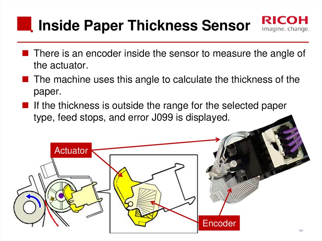
There is an encoder inside the sensor to measure the angle ofthe actuator.
The machine uses this angle to calculate the thickness of the
paper.
If the thickness is outside the range for the selected paper
type, feed stops, and error J099 is displayed.
Actuator
Encoder
131
132. Double-feed Detection
The machine compares the thickness of the current sheetwith the previous sheet.
If the difference between the two is over a certain
threshold (SP1-304-001 to 003), double feed is detected,
feed stops, and JAM099 is displayed.
The double feed detection setting can be
enabled/disabled for each tray (SP1-302-001 to 006).
Default is ‘enabled’.
Even if double feed detection is disabled, the number of
double feed detections is stored (SP1-309-001 to 006).
132
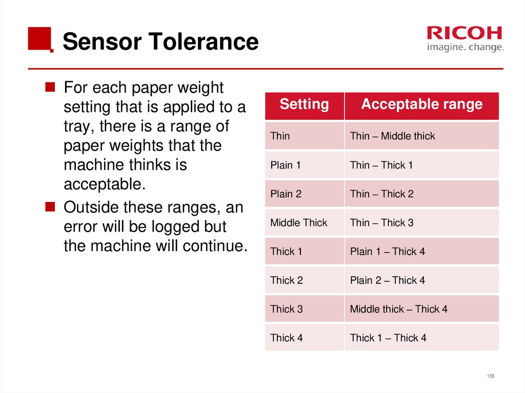
133. Sensor Tolerance
For each paper weightsetting that is applied to a
tray, there is a range of
paper weights that the
machine thinks is
acceptable.
Outside these ranges, an
error will be logged but
the machine will continue.
Setting
Acceptable range
Thin
Thin – Middle thick
Plain 1
Thin – Thick 1
Plain 2
Thin – Thick 2
Middle Thick
Thin – Thick 3
Thick 1
Plain 1 – Thick 4
Thick 2
Plain 2 – Thick 4
Thick 3
Middle thick – Thick 4
Thick 4
Thick 1 – Thick 4
133
134. Paper Thickness Detection Other Points
Sensor error detectionThe paper thickness sensor output value is measured at
power-on/return from energy saver mode/right cover opened
and closed.
At these times, there should be no paper, so the thickness
should be zero.
If a fault is detected, SC511-00 occurs.
The following paper types may be incorrectly detected.
Paper with holes
Recycled paper
Backing paper
Paper of mixed types
134
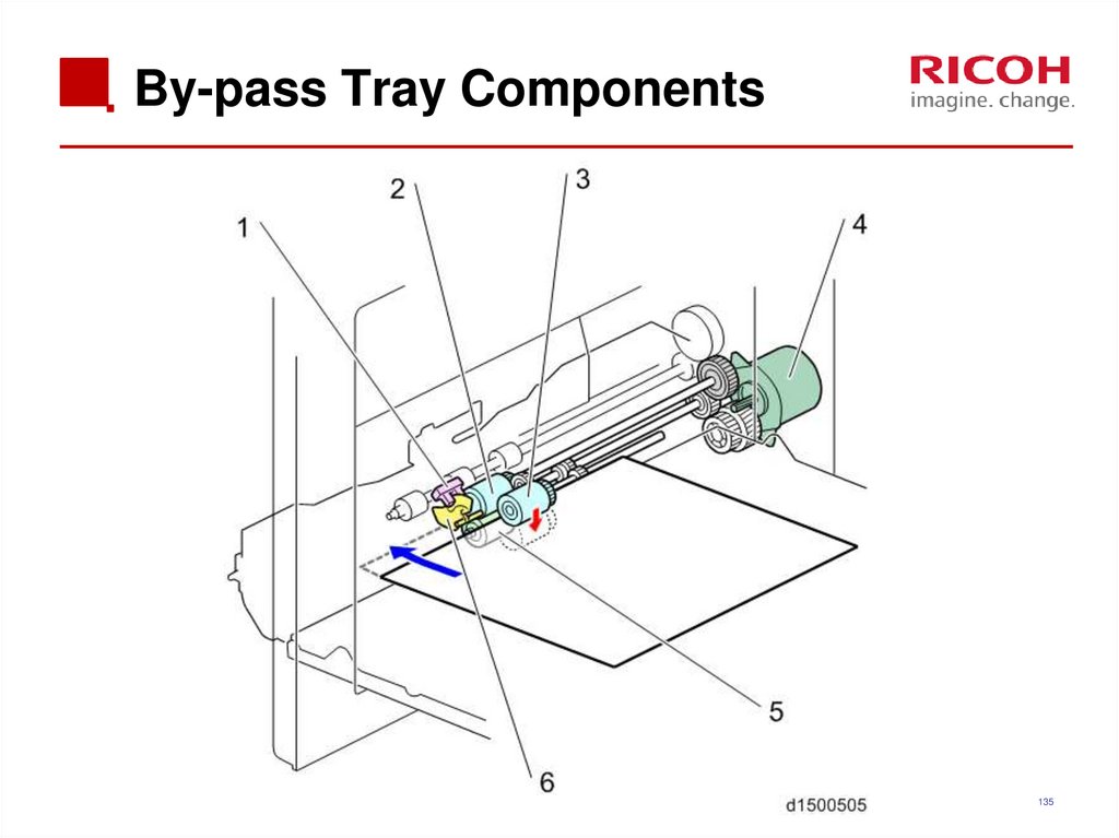
135. By-pass Tray Components
135136. By-pass Tray Size Detection
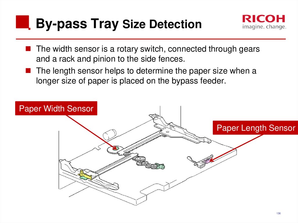
The width sensor is a rotary switch, connected through gearsand a rack and pinion to the side fences.
The length sensor helps to determine the paper size when a
longer size of paper is placed on the bypass feeder.
Paper Width Sensor
Paper Length Sensor
136
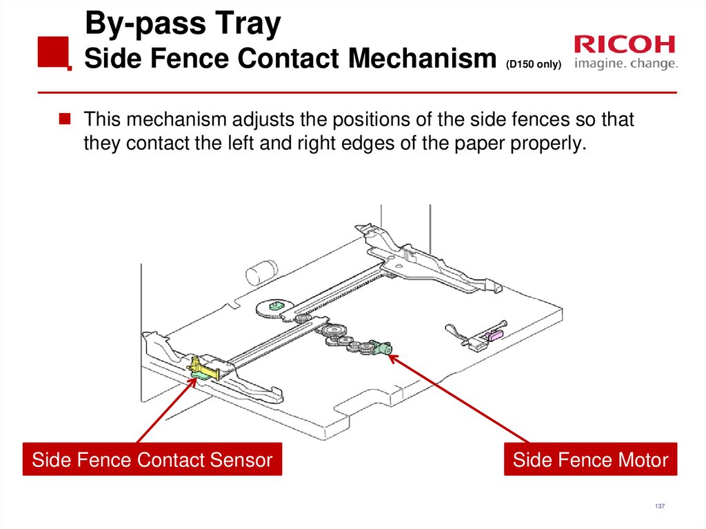
137. By-pass Tray Side Fence Contact Mechanism (D150 only)
This mechanism adjusts the positions of the side fences so thatthey contact the left and right edges of the paper properly.
Side Fence Contact Sensor
Side Fence Motor
137
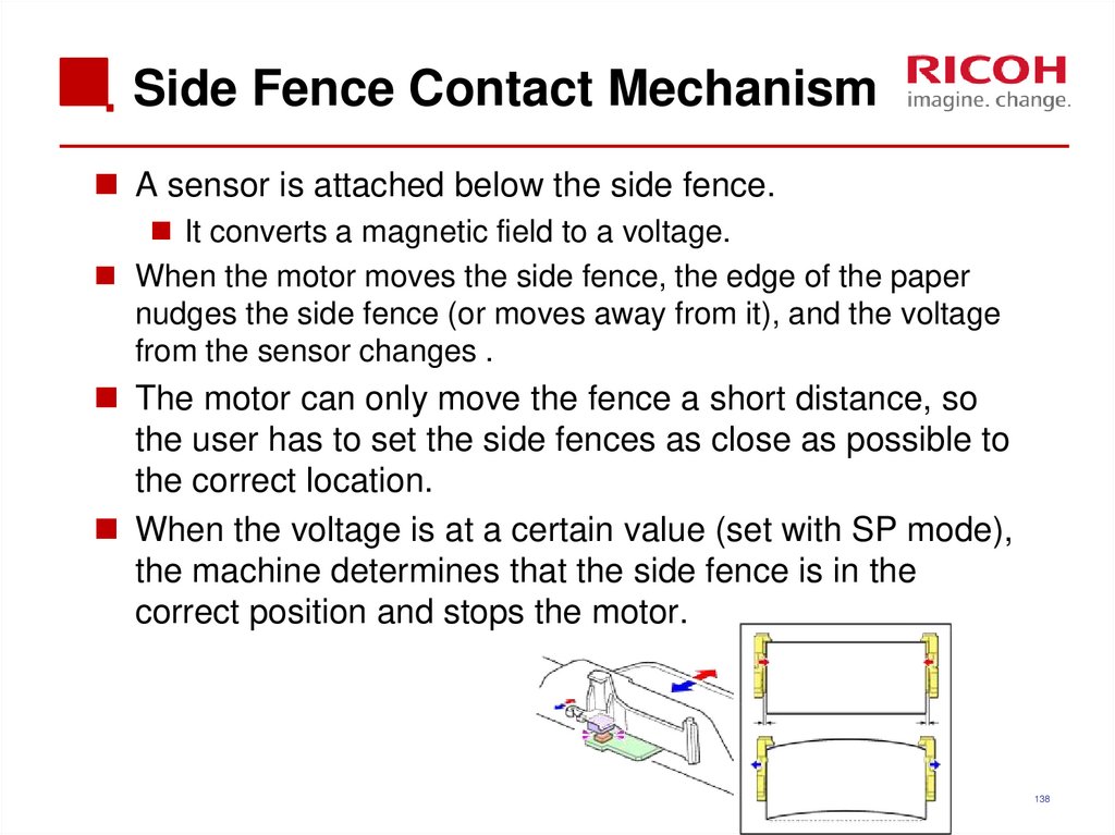
138. Side Fence Contact Mechanism
A sensor is attached below the side fence.It converts a magnetic field to a voltage.
When the motor moves the side fence, the edge of the paper
nudges the side fence (or moves away from it), and the voltage
from the sensor changes .
The motor can only move the fence a short distance, so
the user has to set the side fences as close as possible to
the correct location.
When the voltage is at a certain value (set with SP mode),
the machine determines that the side fence is in the
correct position and stops the motor.
138
139. Exercise
Remove the 1st and 2nd paper feed unit and remove on theD150 the paper thickness sensor according to the field
service manual.
The 1st paper feed unit can be removed without removing
the right side cover(just open the right side cover) and
after pulling out the paper tray, you can remove the paper
feed unit.
Note that the 1st paper feed unit and 2nd paper feed unit
are not interchangeable.
139
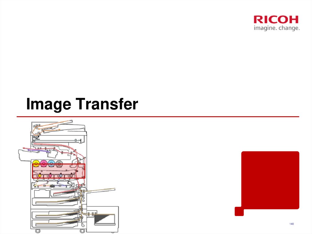
140. Image Transfer
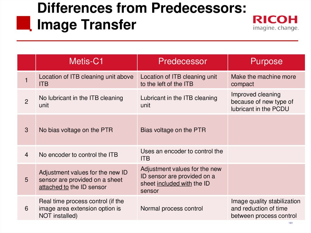
140141. Differences from Predecessors: Image Transfer
Metis-C1Predecessor
Purpose
1
Location of ITB cleaning unit above
ITB
Location of ITB cleaning unit
to the left of the ITB
Make the machine more
compact
2
No lubricant in the ITB cleaning
unit
Lubricant in the ITB cleaning
unit
Improved cleaning
because of new type of
lubricant in the PCDU
3
No bias voltage on the PTR
Bias voltage on the PTR
4
No encoder to control the ITB
Uses an encoder to control the
ITB
5
Adjustment values for the new ID
sensor are provided on a sheet
attached to the ID sensor
Adjustment values for the new
ID sensor are provided on a
sheet included with the ID
sensor
6
Real time process control (if the
image area extension option is
NOT installed)
Normal process control
Image quality stabilization
and reduction of time
between process control
141
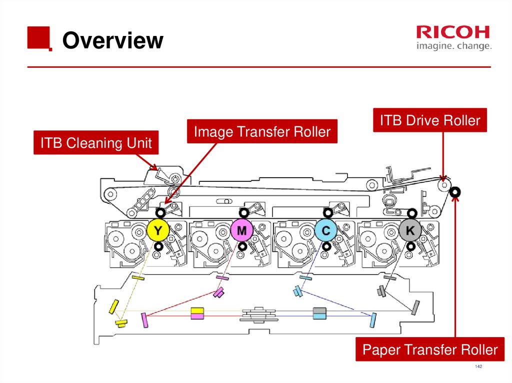
142. Overview
ITB Cleaning UnitImage Transfer Roller
ITB Drive Roller
Paper Transfer Roller
142
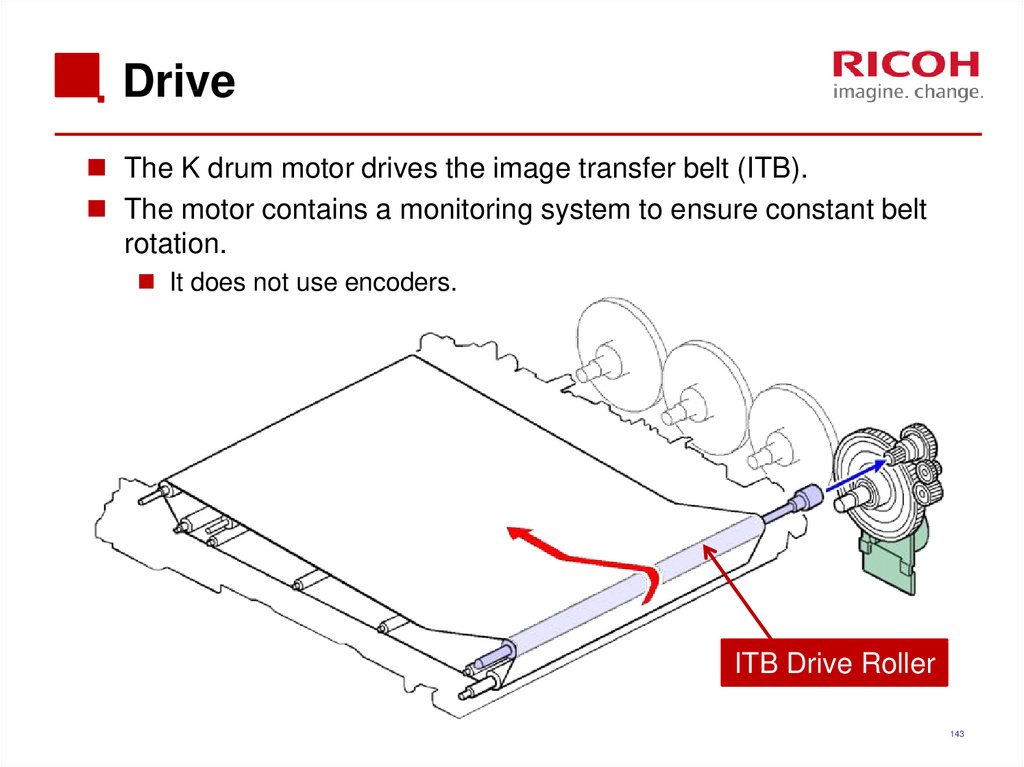
143. Drive
The K drum motor drives the image transfer belt (ITB).The motor contains a monitoring system to ensure constant belt
rotation.
It does not use encoders.
ITB Drive Roller
143
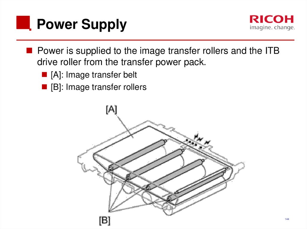
144. Power Supply
Power is supplied to the image transfer rollers and the ITBdrive roller from the transfer power pack.
[A]: Image transfer belt
[B]: Image transfer rollers
144
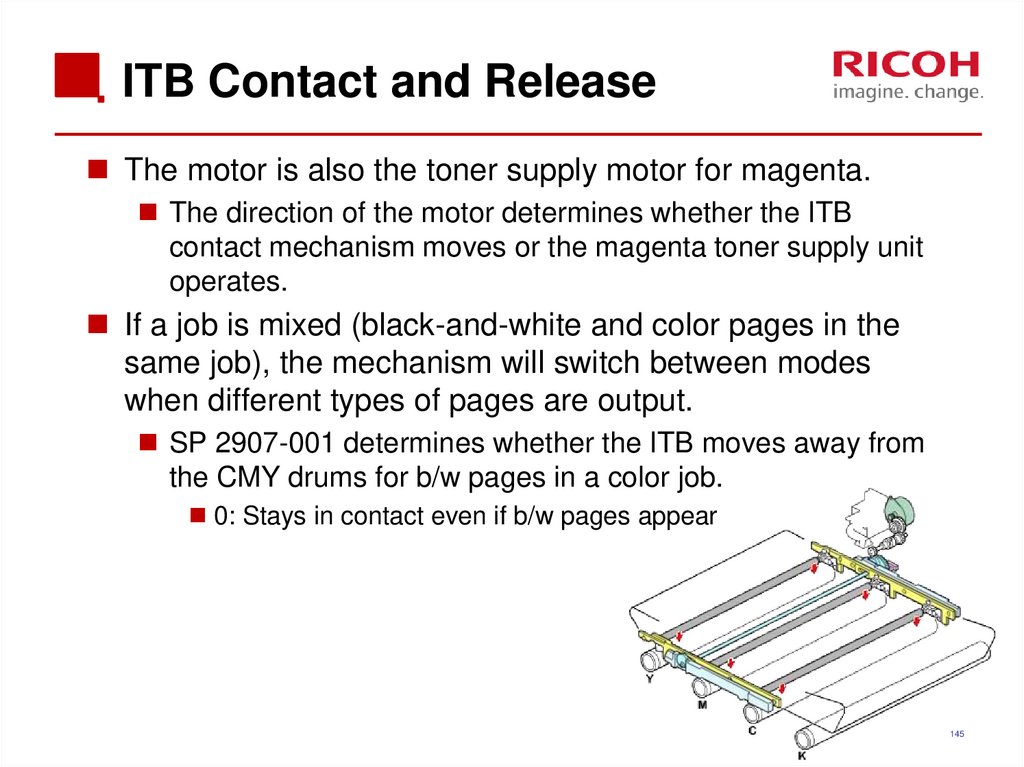
145. ITB Contact and Release
The motor is also the toner supply motor for magenta.The direction of the motor determines whether the ITB
contact mechanism moves or the magenta toner supply unit
operates.
If a job is mixed (black-and-white and color pages in the
same job), the mechanism will switch between modes
when different types of pages are output.
SP 2907-001 determines whether the ITB moves away from
the CMY drums for b/w pages in a color job.
0: Stays in contact even if b/w pages appear
145
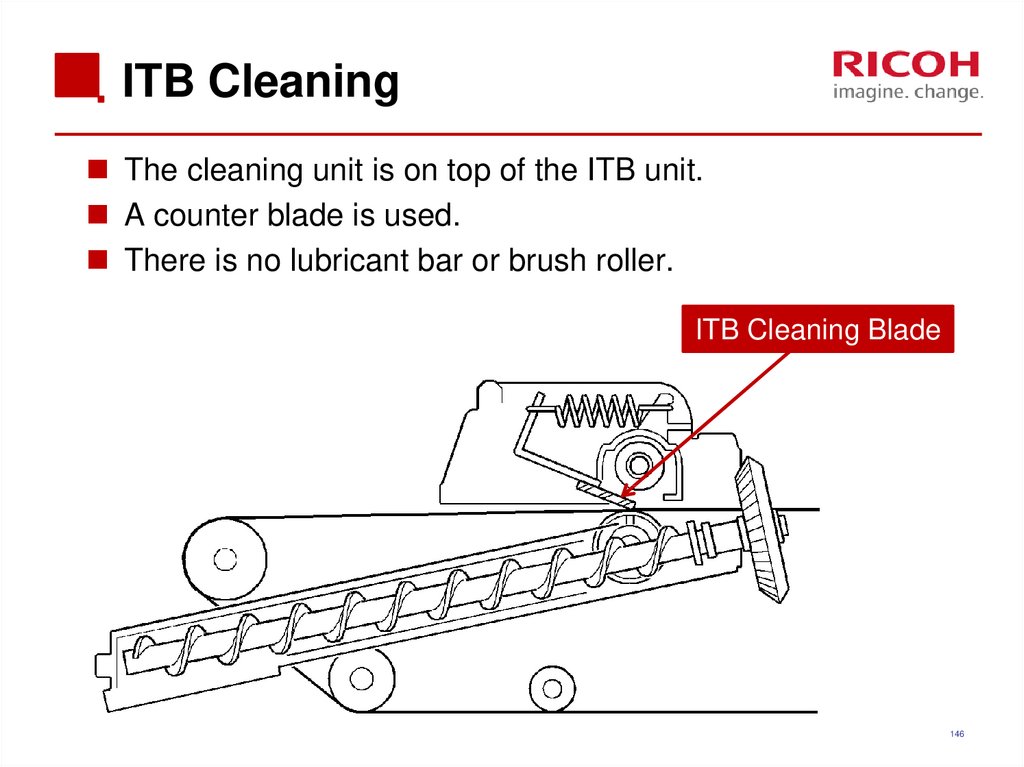
146. ITB Cleaning
The cleaning unit is on top of the ITB unit.A counter blade is used.
There is no lubricant bar or brush roller.
ITB Cleaning Blade
146
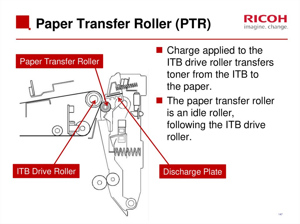
147. Paper Transfer Roller (PTR)
Paper Transfer RollerITB Drive Roller
Charge applied to the
ITB drive roller transfers
toner from the ITB to
the paper.
The paper transfer roller
is an idle roller,
following the ITB drive
roller.
Discharge Plate
147
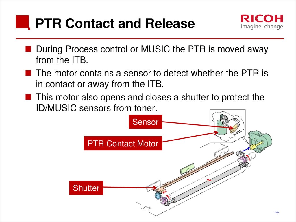
148. PTR Contact and Release
During Process control or MUSIC the PTR is moved awayfrom the ITB.
The motor contains a sensor to detect whether the PTR is
in contact or away from the ITB.
This motor also opens and closes a shutter to protect the
ID/MUSIC sensors from toner.
Sensor
PTR Contact Motor
Shutter
148
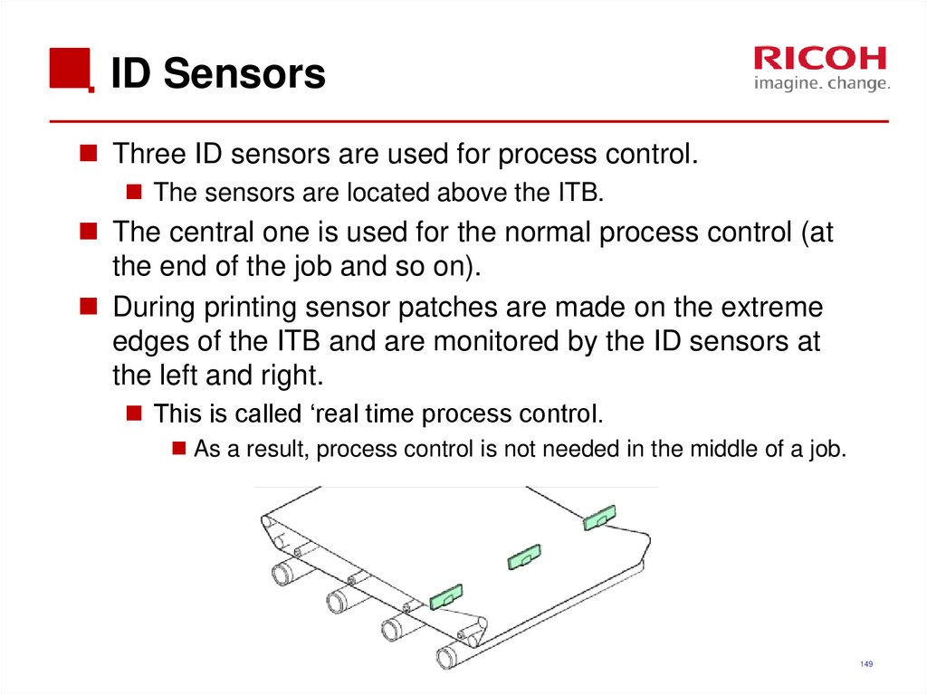
149. ID Sensors
Three ID sensors are used for process control.The sensors are located above the ITB.
The central one is used for the normal process control (at
the end of the job and so on).
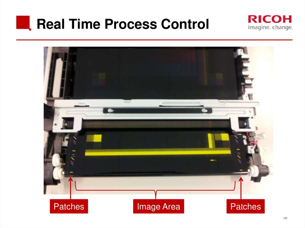
During printing sensor patches are made on the extreme
edges of the ITB and are monitored by the ID sensors at
the left and right.
This is called ‘real time process control.
As a result, process control is not needed in the middle of a job.
149
150. Real Time Process Control
PatchesImage Area
Patches
150
151. Replacement ITB Lever Position
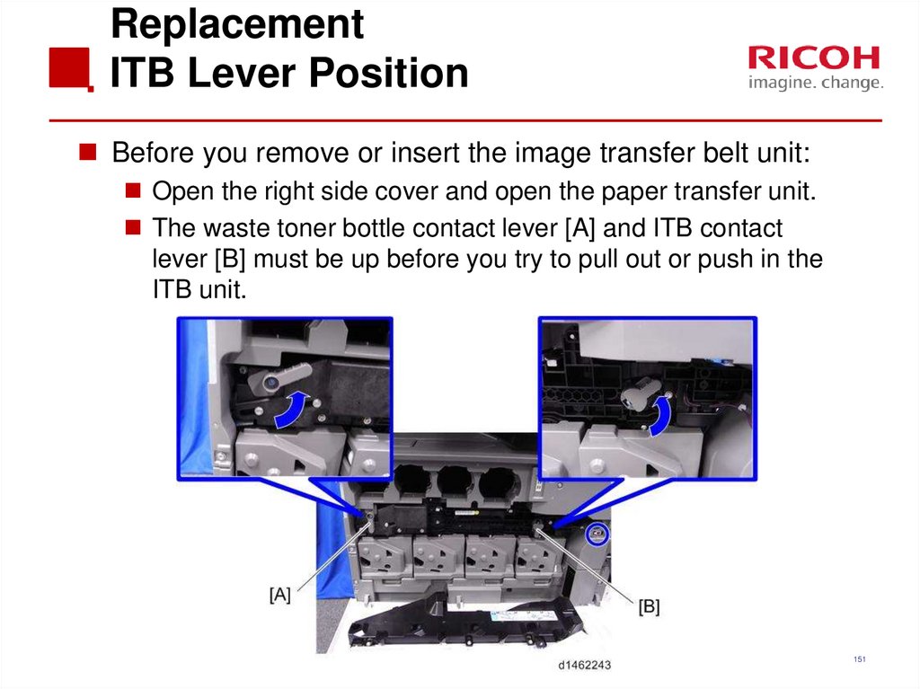
Before you remove or insert the image transfer belt unit:Open the right side cover and open the paper transfer unit.
The waste toner bottle contact lever [A] and ITB contact
lever [B] must be up before you try to pull out or push in the
ITB unit.
151
152. Replacement ITB Cleaning Unit
When removing the ITB cleaning unit:Turn the ITB unit upside down to prevent toner from
coming out of the cleaning unit.
After installing a new cleaning unit
Apply some toner to the ITB.
Then turn the image transfer belt about 10mm in the reverse
direction, then turn it forward one complete revolution.
152
153. Replacement ID Sensors
Before you replace the ID sensor, you must input thevalues 1-6 on the decal for each of the new sensors into
SP mode, or process control/MUSIC will not be done
correctly after power is switched on (it will use the values
for the old sensor).
Make sure that you input the values into the correct SP
modes.
SP3-333-001 to 3-333-006: front
SP3-334-001 to 3-334-006: center
SP3-335-001 to 3-335-006: rear
After you replace the sensor, do SP3-011-004 (full
MUSIC)
153
154. Fusing
154155. Differences from Predecessors: Fusing
Metis-C1Predecessor
Fusing sleeve material
Purpose
1
Fusing sleeve material change
(Ni+Cu)
2
Two heaters + Shield
3
Fusing unit replacement required
only at SC544-02/554-02
occurrence
Fusing unit replacement
required at SC544-00/554-00/
564-00/ 574-00 occurrence
To optimize the
replacement timing of the
fusing unit
4
Grease for use with metal
(Fluotraibo) is used on the
pressure roller and the bushing
Grease for use with plastic is
used on the pressure roller and
the bushing (Barierta)
Improved lubrication
5
Pressure release motor turns only
one way
Pressure release motor turn
both ways
Machine layout change
(SUS: stainless)
Three heaters
(one is for postcards)
Stronger material
AC-TEC reduction
155
156. Components
Athena & Apollon-C3156
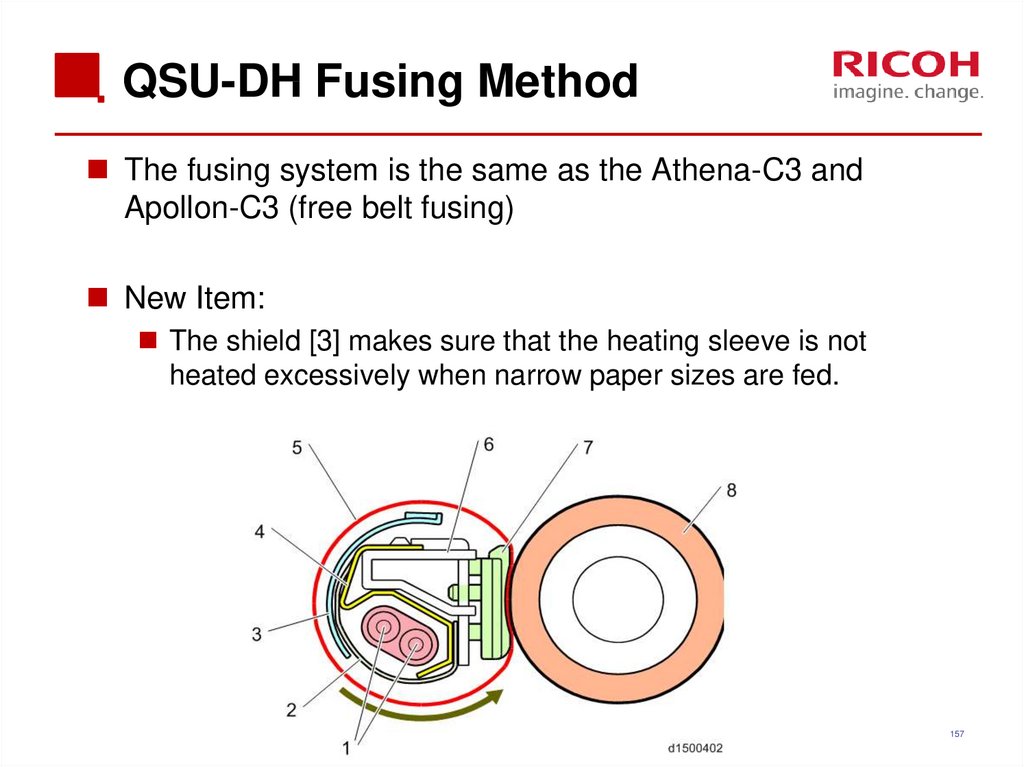
157. QSU-DH Fusing Method
The fusing system is the same as the Athena-C3 andApollon-C3 (free belt fusing)
New Item:
The shield [3] makes sure that the heating sleeve is not
heated excessively when narrow paper sizes are fed.
157
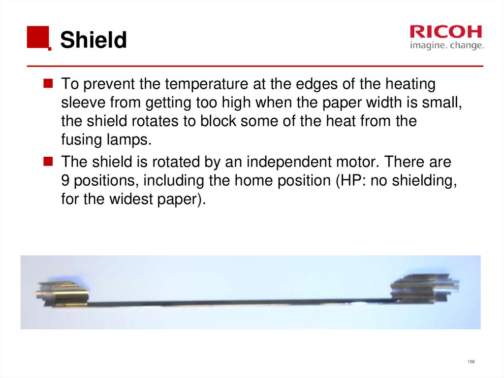
158. Shield
To prevent the temperature at the edges of the heatingsleeve from getting too high when the paper width is small,
the shield rotates to block some of the heat from the
fusing lamps.
The shield is rotated by an independent motor. There are
9 positions, including the home position (HP: no shielding,
for the widest paper).
158
159. Shield Rotation
AB
C
E
F
G
H
D
I
J
159
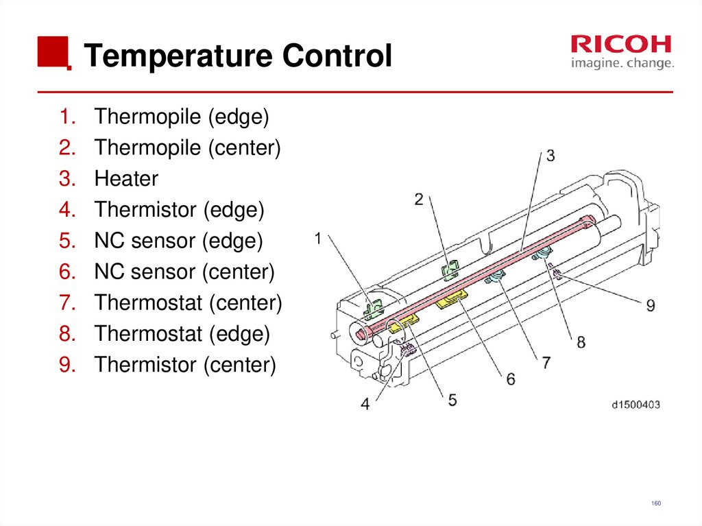
160. Temperature Control
1.2.
3.
4.
5.
6.
7.
8.
9.
Thermopile (edge)
Thermopile (center)
Heater
Thermistor (edge)
NC sensor (edge)
NC sensor (center)
Thermostat (center)
Thermostat (edge)
Thermistor (center)
160
161. CPM Down Control Handling Low Temperatures
The central thermopile is checked at regular intervals, andif the temperature is too low, the CPM is reduced in three
stages.
100% > 80% > 65% > 50%
161
162. CPM Down Control Handling High Temperatures
Because the fusing unit has a low heat capacity, thetemperature of those parts of the heating sleeve outside
the paper width easily increases, and may get extremely
hot.
Therefore CPM down is implemented in the following 3
levels depending on the detected temperature, or the
paper passage time.
100 > 80 > 50 > 30 (for normal paper, A3/A4)
There are differences depending on paper size/paper
thickness.
162
163. Fusing Temperature Detection
The temperature is checked at regular intervals.If the temperature is above a certain value, the CPM is
decreased by 1 level.
Since the points at which temperature tends to increase
depends on the paper size, the sensor used is changed
depending on the paper size.
A3/B4: Thermistor (pressure roller end)
A4: Thermopile (end)
B5/A5/B6/A6: Thermistor (pressure roller center)
163
164. Paper Passage Time
Depending on the paper size, it may not be possible touse a sensor to monitor the points on the heating sleeve
which tend to get hotter.
Therefore, time conditions are also used to determine
CPM down and if continuous paper passage time is above
a threshold value, CPM is decreased by 1 level.
164
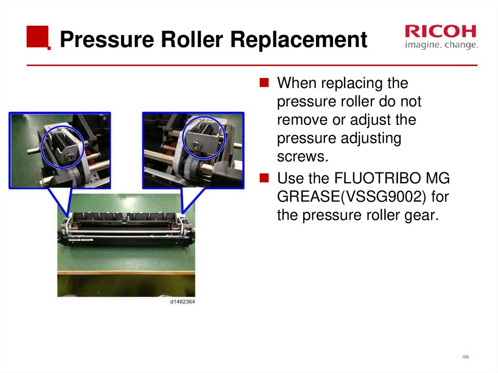
165. Pressure Roller Replacement
When replacing thepressure roller do not
remove or adjust the
pressure adjusting
screws.
Use the FLUOTRIBO MG
GREASE(VSSG9002) for
the pressure roller gear.
165
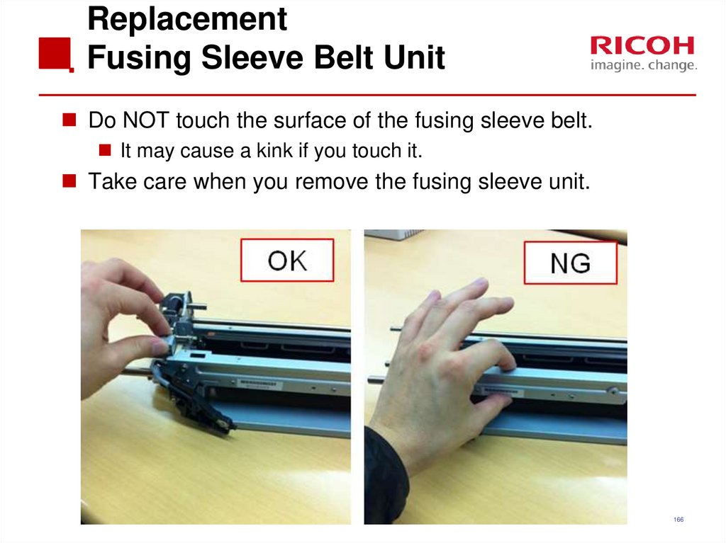
166. Replacement Fusing Sleeve Belt Unit
Do NOT touch the surface of the fusing sleeve belt.It may cause a kink if you touch it.
Take care when you remove the fusing sleeve unit.
166
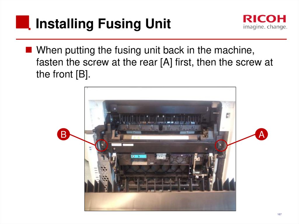
167. Installing Fusing Unit
When putting the fusing unit back in the machine,fasten the screw at the rear [A] first, then the screw at
the front [B].
B
A
167
168. Fusing Shield Motor Test
Remove the fusing unit.The motor rotation is not visible when the fusing unit is in the
machine.
Remove the waste toner bottle.
This is necessary as an additional safety measure to disable
the fusing unit so that the fusing lamps will not heat the
sleeve belt.
Do SP 5-804-235 or -236 (clockwise or counterclockwise
rotation).
168
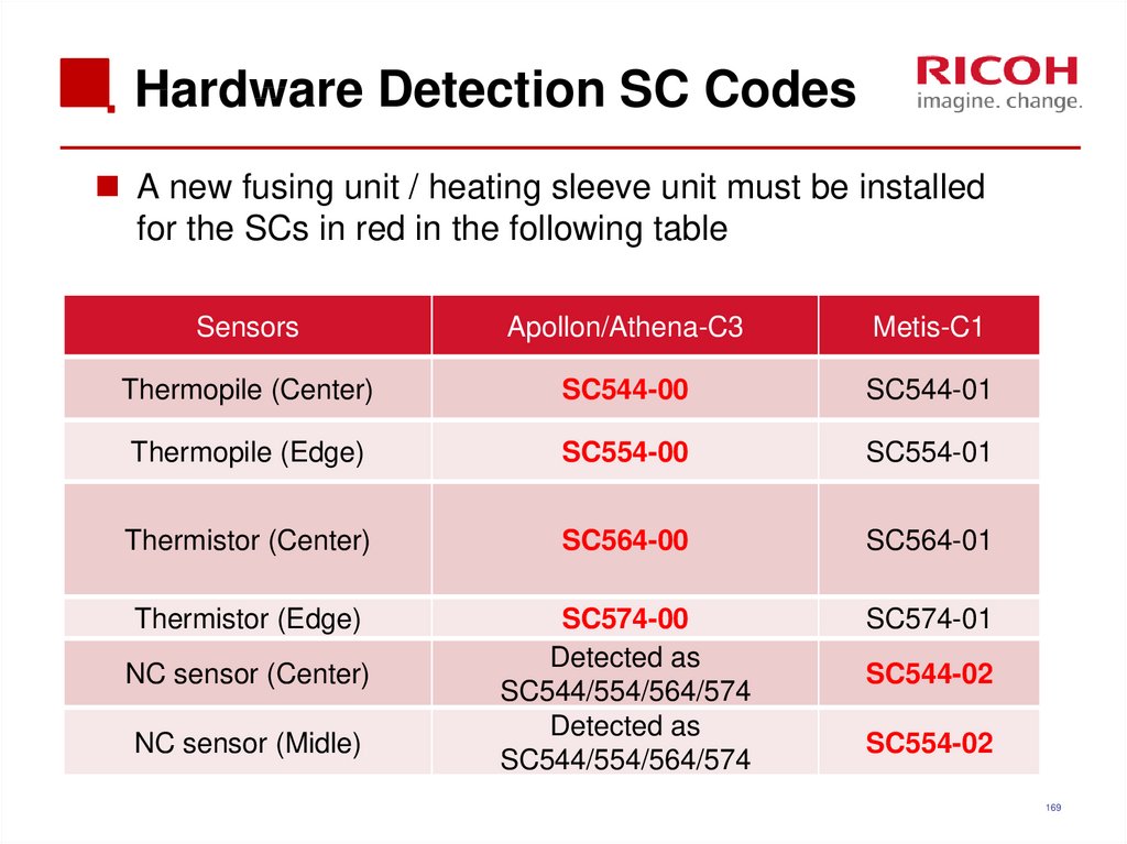
169. Hardware Detection SC Codes
A new fusing unit / heating sleeve unit must be installedfor the SCs in red in the following table
Sensors
Apollon/Athena-C3
Metis-C1
Thermopile (Center)
SC544-00
SC544-01
Thermopile (Edge)
SC554-00
SC554-01
Thermistor (Center)
SC564-00
SC564-01
Thermistor (Edge)
SC574-00
Detected as
SC544/554/564/574
Detected as
SC544/554/564/574
SC574-01
NC sensor (Center)
NC sensor (Midle)
SC544-02
SC554-02
169
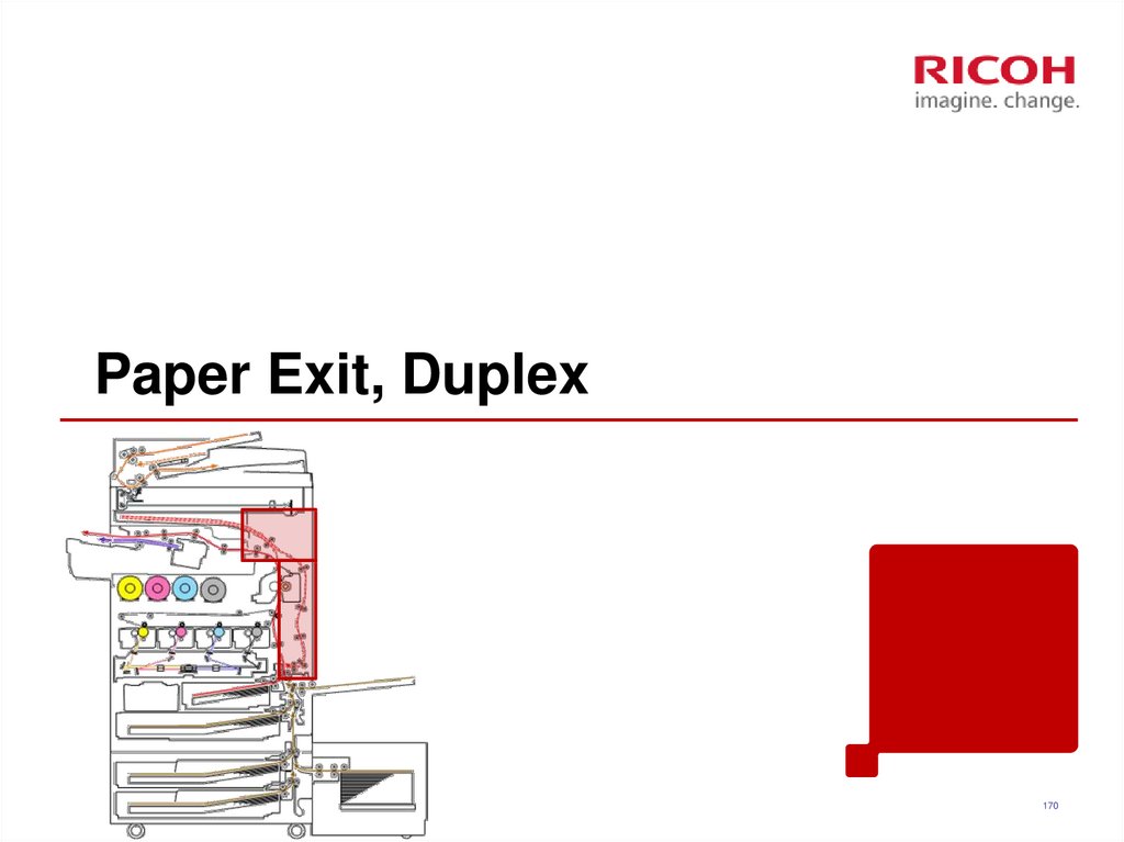
170. Paper Exit, Duplex
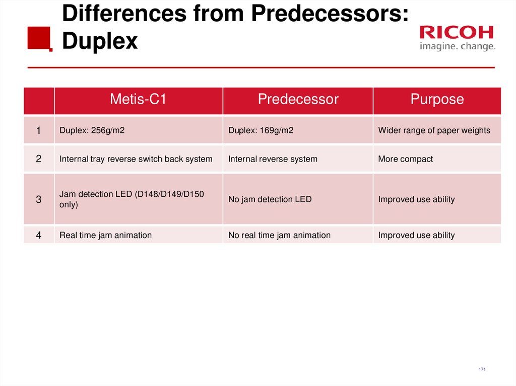
170171. Differences from Predecessors: Duplex
Metis-C1Predecessor
Purpose
1
Duplex: 256g/m2
Duplex: 169g/m2
Wider range of paper weights
2
Internal tray reverse switch back system
Internal reverse system
More compact
3
Jam detection LED (D148/D149/D150
only)
No jam detection LED
Improved use ability
4
Real time jam animation
No real time jam animation
Improved use ability
171
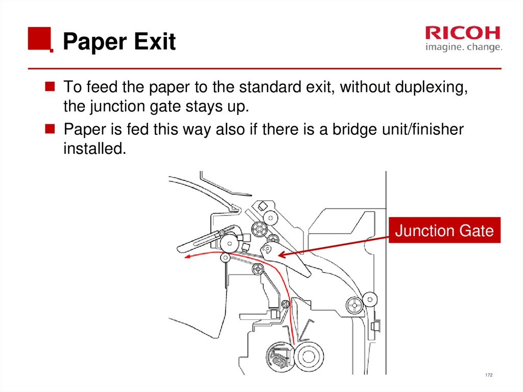
172. Paper Exit
To feed the paper to the standard exit, without duplexing,the junction gate stays up.
Paper is fed this way also if there is a bridge unit/finisher
installed.
Junction Gate
172
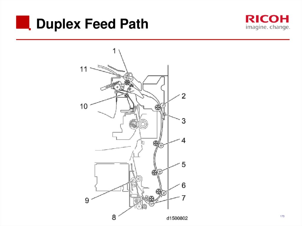
173. Duplex Feed Path
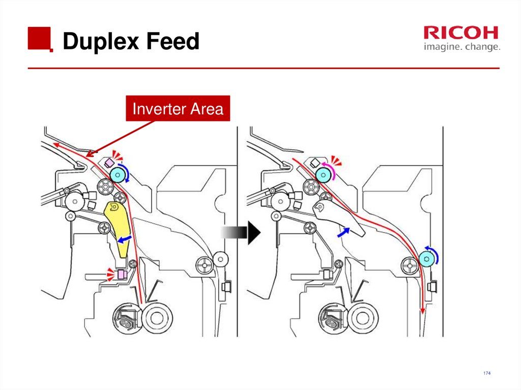
173174. Duplex Feed
Inverter Area174
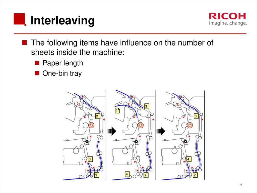
175. Interleaving
The following items have influence on the number ofsheets inside the machine:
Paper length
One-bin tray
175
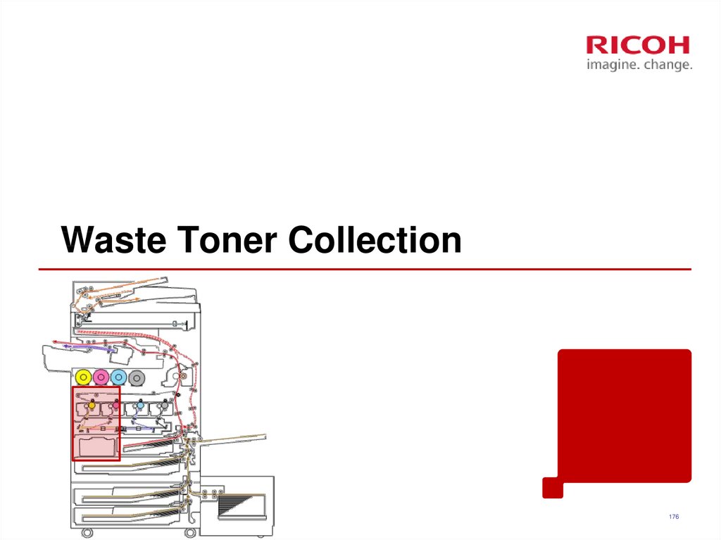
176. Waste Toner Collection
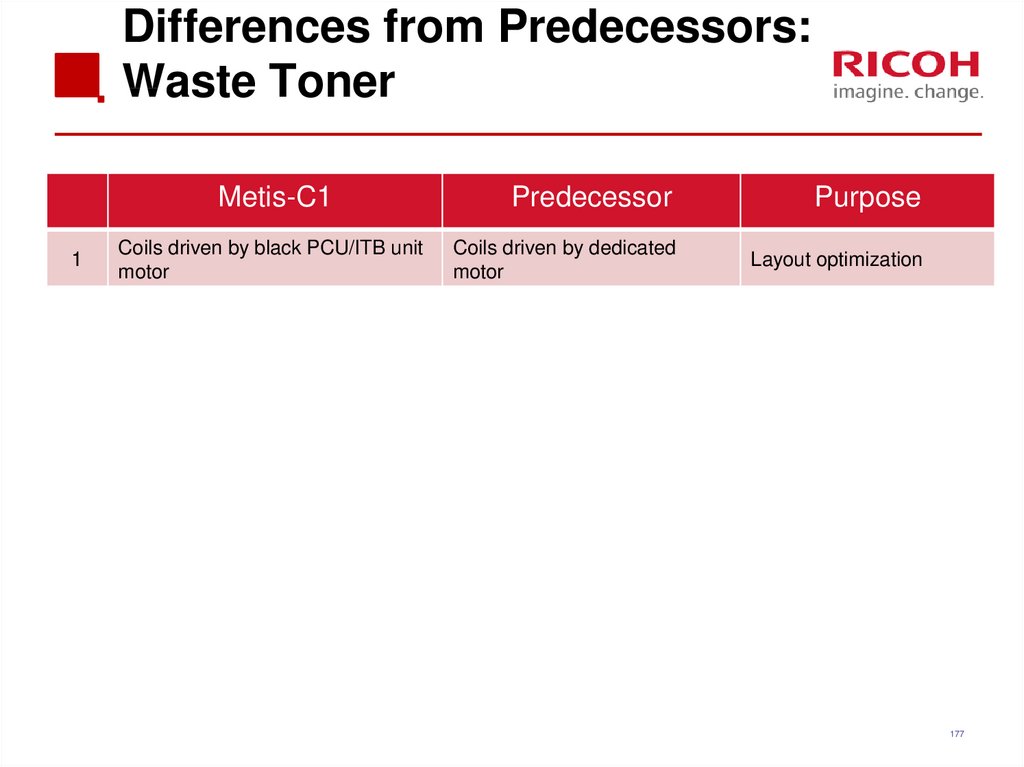
176177. Differences from Predecessors: Waste Toner
Metis-C11
Coils driven by black PCU/ITB unit
motor
Predecessor
Purpose
Coils driven by dedicated
motor
Layout optimization
177
178. Collection Coils
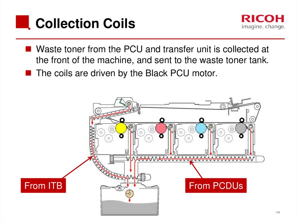
Waste toner from the PCU and transfer unit is collected atthe front of the machine, and sent to the waste toner tank.
The coils are driven by the Black PCU motor.
From ITB
From PCDUs
178
179. Sensors
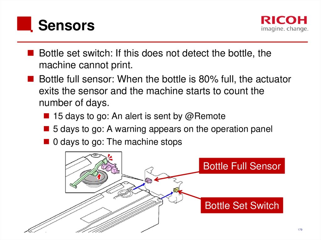
Bottle set switch: If this does not detect the bottle, themachine cannot print.
Bottle full sensor: When the bottle is 80% full, the actuator
exits the sensor and the machine starts to count the
number of days.
15 days to go: An alert is sent by @Remote
5 days to go: A warning appears on the operation panel
0 days to go: The machine stops
Bottle Full Sensor
Bottle Set Switch
179
180. 5. Troubleshooting
180181. Capturing the Debug Logs (1/3)
Debug logs for the controller, engine, and operation panelcan be transferred to an SD card in the SD slot on the
operation panel.
The controller debug is updated continuously during
operation, but the engine debug log is only changed if an SC
or jam occurs.
In older models, a technician enabled the logging tool
after a problem occurred.
After that, when the problem had been reproduced, the
technician was able to retrieve the debug log.
However, this new feature saves the debug logs at the
time that problems occur.
Then you can copy the logs to an SD card.
181
182. Capturing the Debug Logs (2/3)
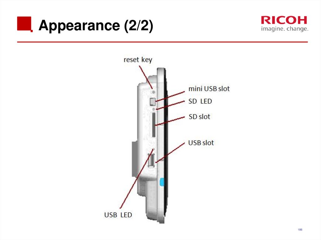
Insert the SD card into the slot on the side of the operationpanel.
Set the start date of the log with SP5-857-101
e.g.: March 28, 2013: input 20130328 (yyyymmdd)
Set the date three days earlier than the occurrence of the
problems.
Set the end date of the log with SP5-857-102
e.g.: March 30, 2013: input 20130330 (yyyymmdd)
Execute SP5-857-103 to write the debug log to the SD
card.
The approximate time it takes to transfer the debug log is as
follows.
Controller debug log (GW debug log): 2 - 20 minutes
Engine debug log: 2 minutes
Operation panel debug log: 2 - 20 minutes
182
183. Capturing the Debug Logs (3/3)
The debug logs are saved with the following file namesand paths.
Controller debug log (GW debug log):
/LogTrace/machine number/watching/
yyyymmdd_hhmmss_unique identification number.gz
Engine debug log:
/LogTrace/machine number/engine/
yyyymmdd_hhmmss.gz
Operation panel debug log:
/LogTrace/machine number/opepanel/
yyyymmdd_hhmmss.tar.gz
183
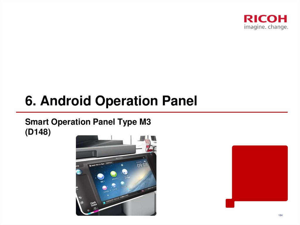
184. 6. Android Operation Panel
Smart Operation Panel Type M3(D148)
184
185. Appearance (1/2)
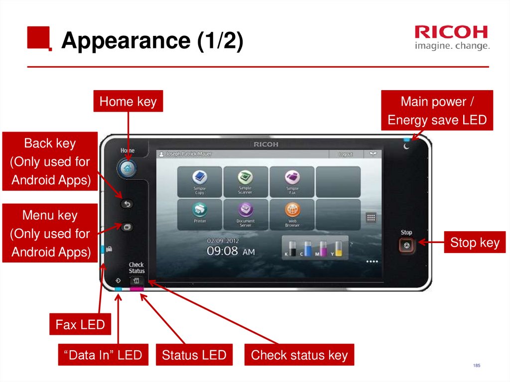
Home keyMain power /
Energy save LED
Back key
(Only used for
Android Apps)
Menu key
(Only used for
Android Apps)
Stop key
Fax LED
“Data In” LED
Status LED
Check status key
185
186. Appearance (2/2)
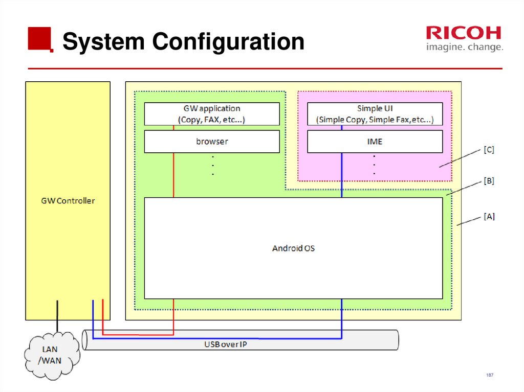
186187. System Configuration
187188. Basic information (1/3)
There are two kinds of applications.1) Android applications
You can use “flick input” and “swiping”.
You can use “Menu” and “Back” keys.
These keys only light for Android applications.
2) Legacy applications (GW Controller)
You cannot use “flick input” or “swiping”.
You cannot use the “Menu” and “back” keys.
188
189. Basic information (2/3)
You can customize the Home display.You can add widgets (Toner remaining, clock, language and
so on) and applications.
Press and hold the Home display
Select the object which you want to add.
You can delete widgets or application icons.
Press and hold the object which you want to delete.
After the trash box appears, move the object to the trash box.
189
190. Basic information (3/3)
SC or machine status is displayed in legacy mode.There is no independent Address Book or Authentication
for Android.
190
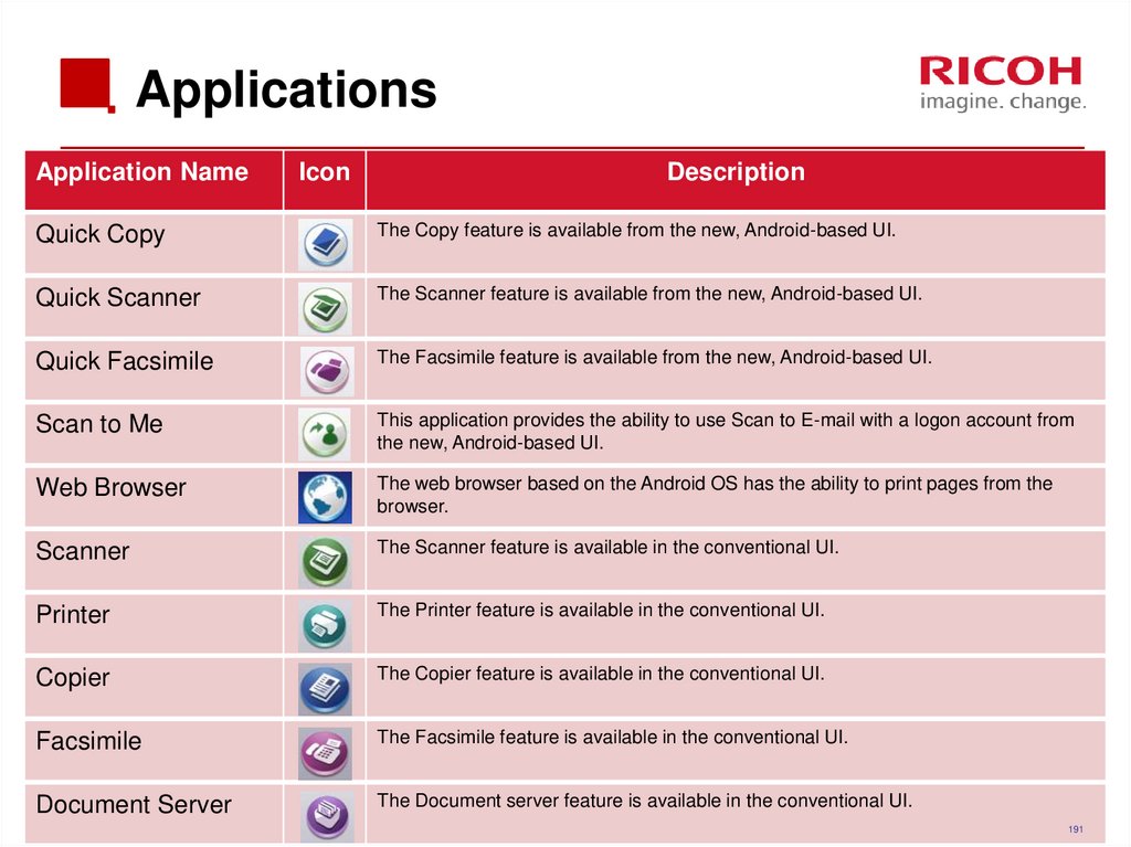
191. Applications
Application NameIcon
Description
Quick Copy
The Copy feature is available from the new, Android-based UI.
Quick Scanner
The Scanner feature is available from the new, Android-based UI.
Quick Facsimile
The Facsimile feature is available from the new, Android-based UI.
Scan to Me
This application provides the ability to use Scan to E-mail with a logon account from
the new, Android-based UI.
Web Browser
The web browser based on the Android OS has the ability to print pages from the
browser.
Scanner
The Scanner feature is available in the conventional UI.
Printer
The Printer feature is available in the conventional UI.
Copier
The Copier feature is available in the conventional UI.
Facsimile
The Facsimile feature is available in the conventional UI.
Document Server
The Document server feature is available in the conventional UI.
191
191
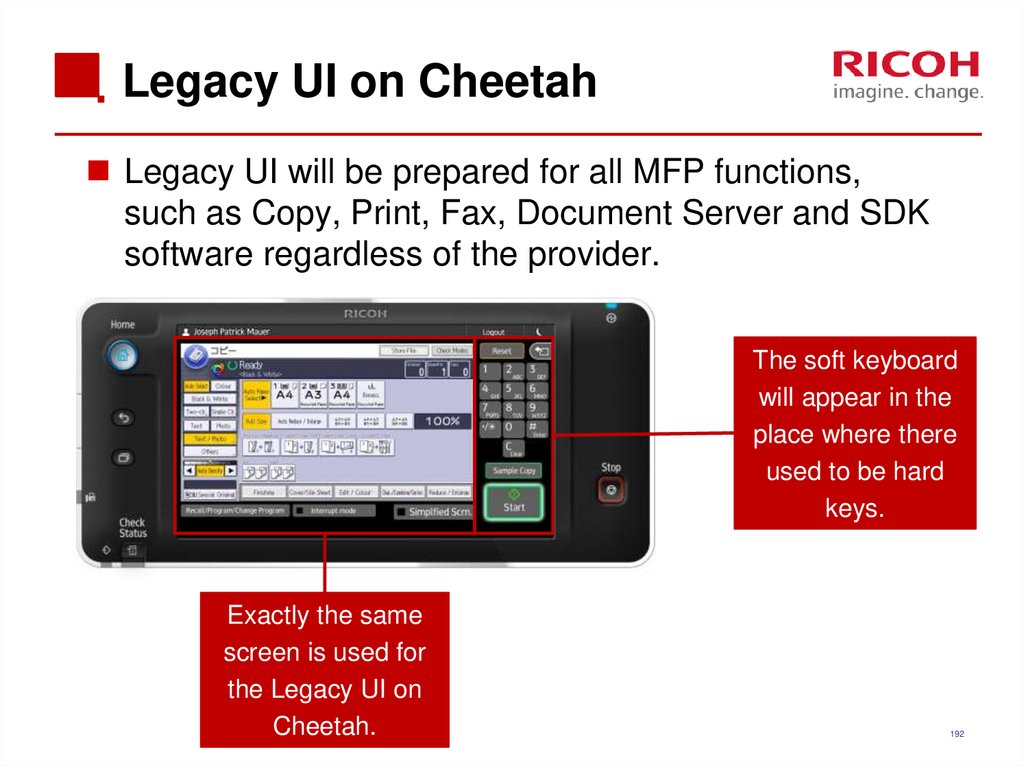
192. Legacy UI on Cheetah
Legacy UI will be prepared for all MFP functions,such as Copy, Print, Fax, Document Server and SDK
software regardless of the provider.
The soft keyboard
will appear in the
place where there
used to be hard
keys.
Exactly the same
screen is used for
the Legacy UI on
Cheetah.
192
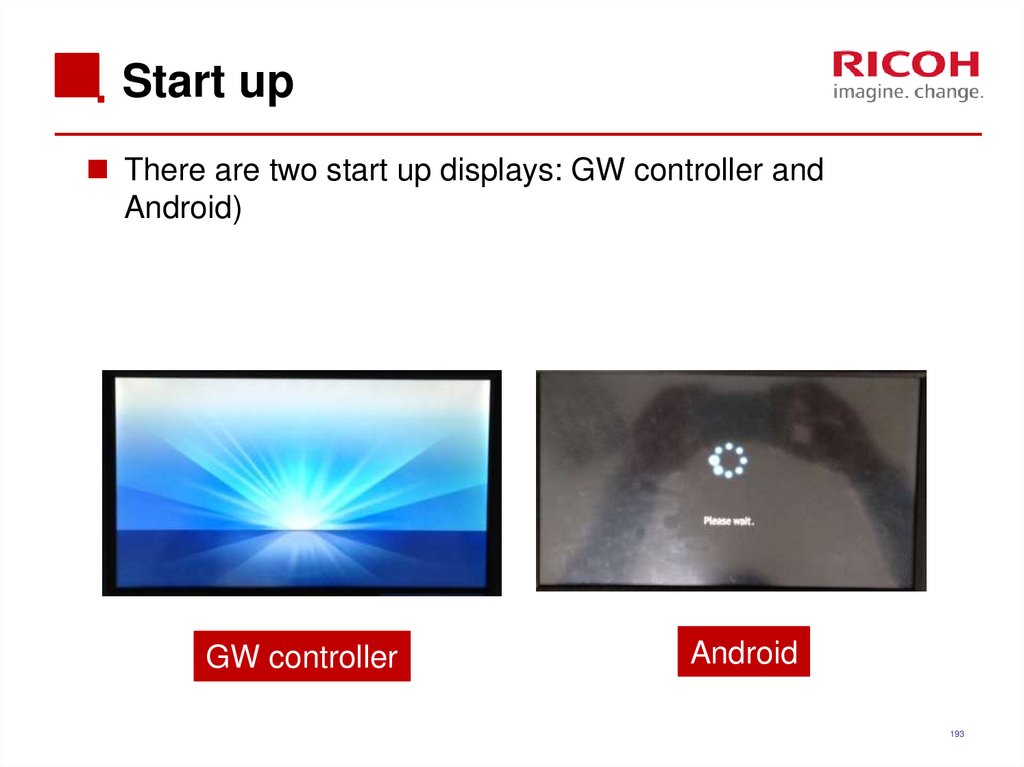
193. Start up
There are two start up displays: GW controller andAndroid)
GW controller
Android
193
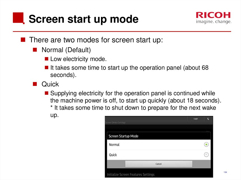
194. Screen start up mode
There are two modes for screen start up:Normal (Default)
Low electricity mode.
It takes some time to start up the operation panel (about 68
seconds).
Quick
Supplying electricity for the operation panel is continued while
the machine power is off, to start up quickly (about 18 seconds).
* It takes some time to shut down to prepare for the next wake
up.
194
195. Special shut down mode
There are two special shut down modes:Shut down for maintenance.
When “Quick” start up mode is set, just enough power is
supplied to keep the panel in sleep condition.
Procedure: Turn the power off while pushing the “Stop” key.
Continue pressing the power switch until "Shutting Down" is
displayed.
Shut down for main machine update.
You can shut down only the Controller and the Engine (without
Android) with this method.
Procedure: Turn the power off while pushing the “Back” key.
Continue pressing the power switch until "Shutting Down" is
displayed.
195
196. Service Modes
There are three SP modes.Machine service mode
Android operation panel service mode
Recovery mode: Needed for updating firmware, and for
android system recovery
196
197.
END24/10/2019
Version: [###] Classification: Internal Owner: [Insert name]
197







 electronics


