

 HIGH LIFT Slats and flaps achieve the high lift function.")

 COMPUTERS A computer arrangement permanently controls and")
 ACTIVE SERVO CONTROLS There are two servo controls for")


 PITCH ATTITUDE PROTECTION If the aircraft reaches the pitch attitude protection nose")
 HIGH ANGLE OF ATTACK PROTECTION The high Angle Of Attack (AOA) protection is")
 HIGH ANGLE OF ATTACK PROTECTION (continued) With autothrust inoperative or not engaged, the speed can")

 HIGH SPEED PROTECTION The high speed protection is designed to prevent the aircraft")
 BANK ANGLE PROTECTION Under normal law, bank angle protection limits the angle of")
 and")


 ELAC 1+2 FAILURE In case of loss of both ELACs only spoilers are")

 ELAC 1 SERVO CONTROLS FAILURE In case of failure of both")
 FAILURES ON THE SAME AILERON In case of failure of both")

 SPOILER SERVO CONTROL FAILURE In case of failure of a")


 send commands")


 becomes")


 is such that a single")


 ONE SOLENOID VALVE DE-ENERGIZED ONLY In case of a single electrical")

 HYDRAULIC FAILURE With no hydraulic pressure, the two selector")


 and")

 2 fails, the control goes to")

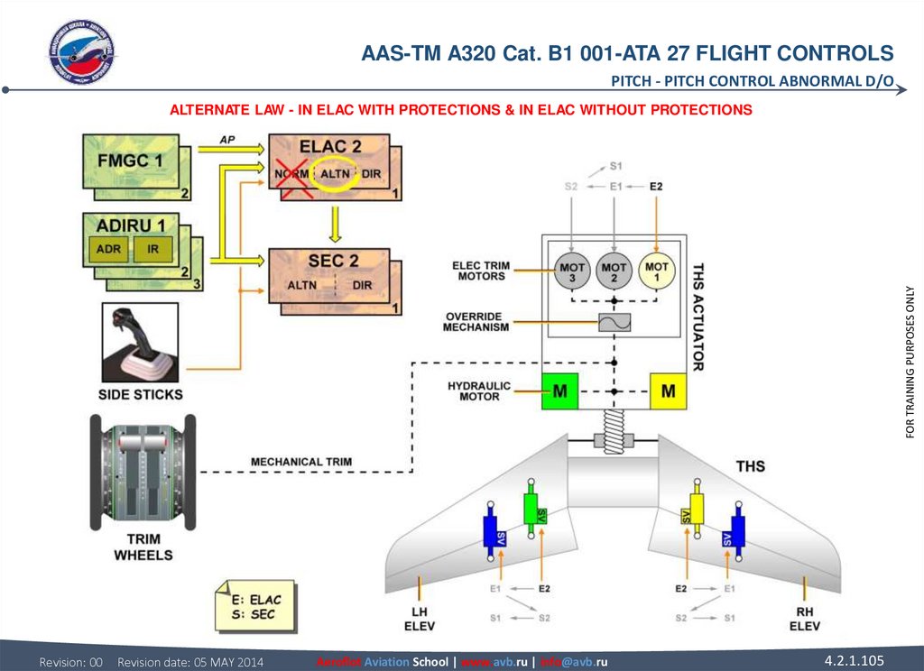
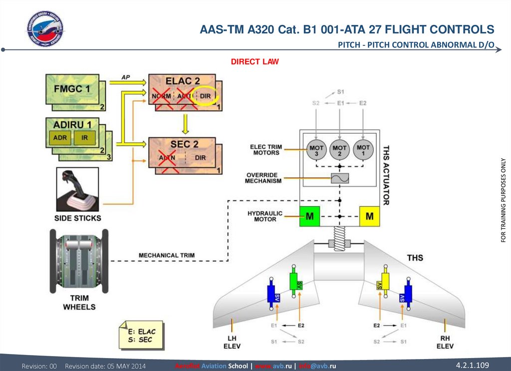
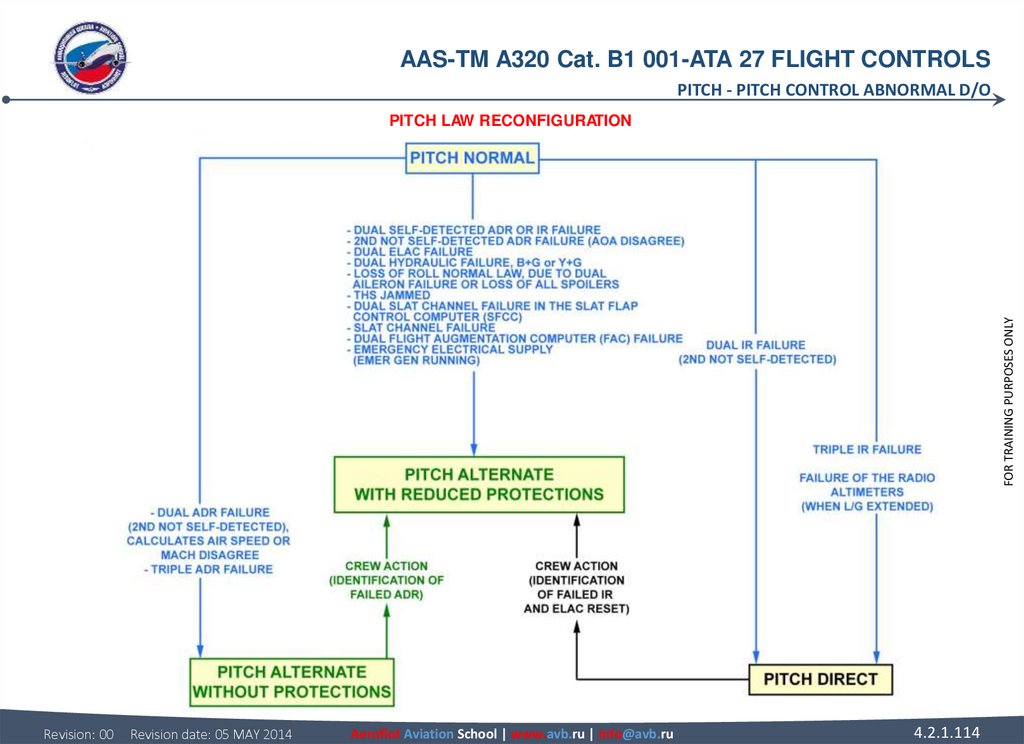
 IN SEC After a double ELAC failure, alternate law with or without")


, the related solenoid valve is")


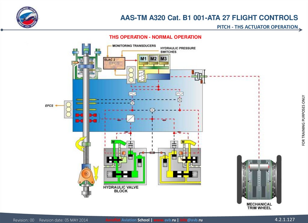
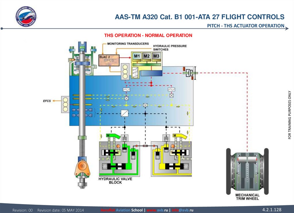
 NORMAL OPERATION ELAC2 (in normal control) sends a drive command to the")

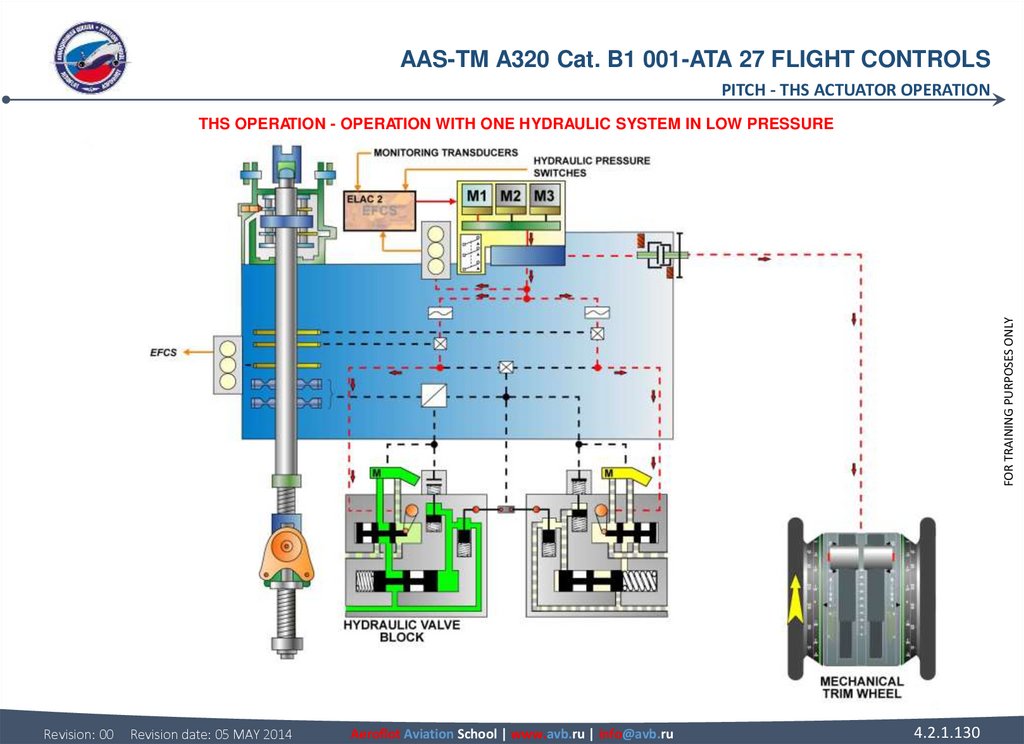
 OPERATION WITH ONE HYDRAULIC SYSTEM IN LOW PRESSURE Since the yellow hydraulic")


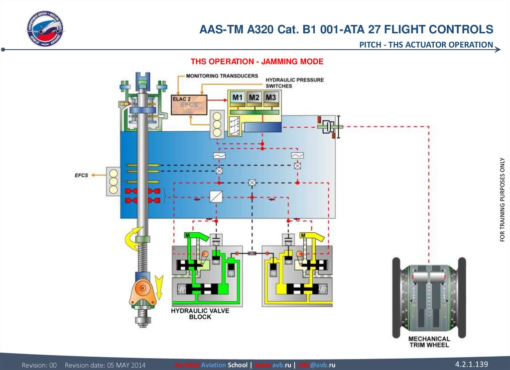
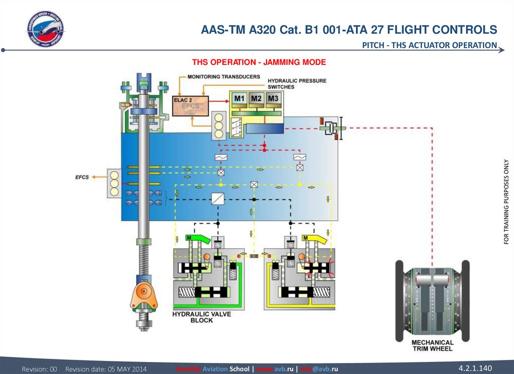
 THS MECHANICAL INPUT A mechanical input link is connected to an override")


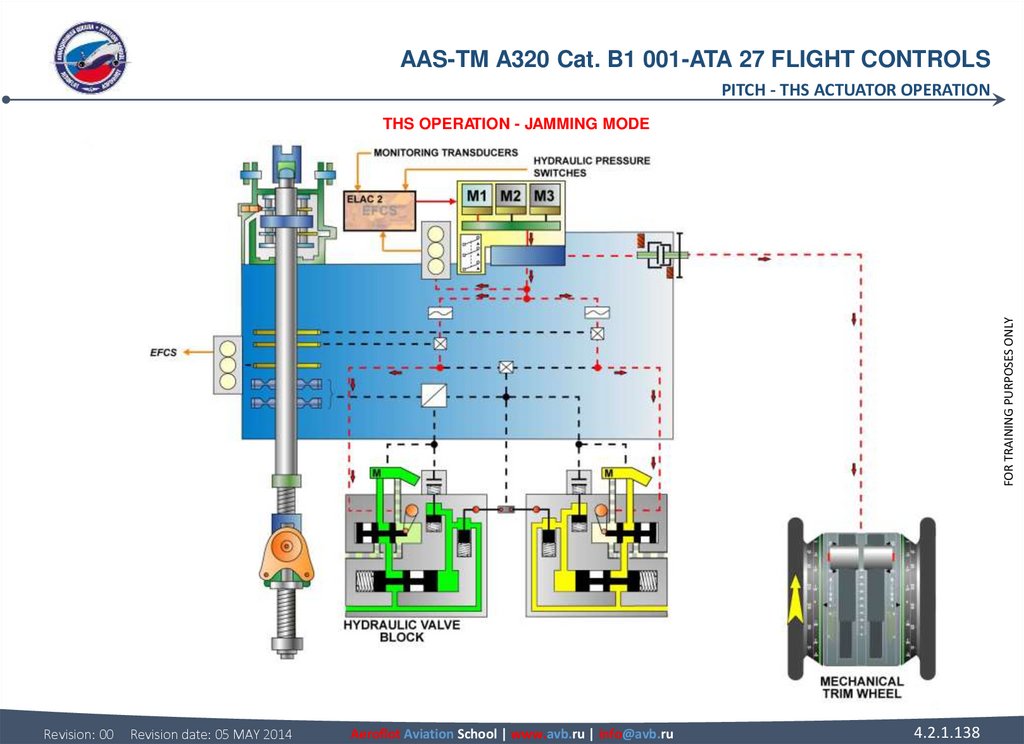
 JAMMING MODE ELAC2 (in normal control) sends a drive command to the servomotor")


 transmits air data and inertial reference data to")

 transmit L/G position information to the")
 transmit slat flap surface position to the ELACs and SECs")
 transmits the altitude information to the ELACs for flare law activation.")


 by the")

,")

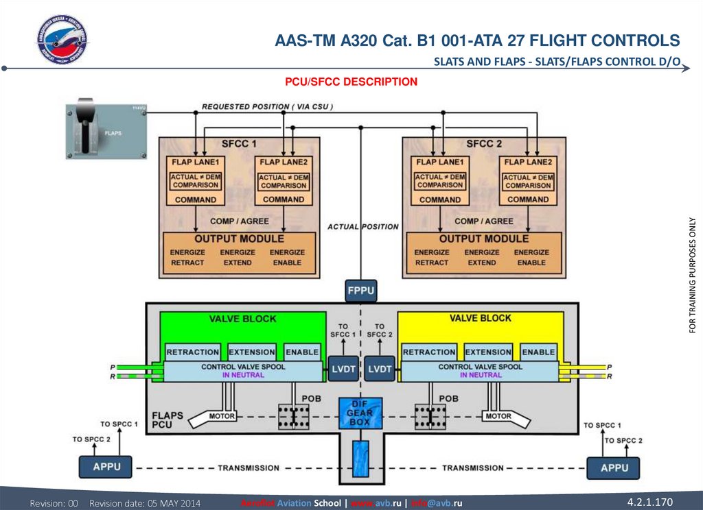
 HIGH SPEED MOVEMENT The enable solenoid valve is energized to release the")

 LOW SPEED MOVEMENT As the flap approaches the requested position, detected")

 application logic.")


 2 flap channel is")


 to the")


 incorporates two hydraulic motors, each one controlled by an")
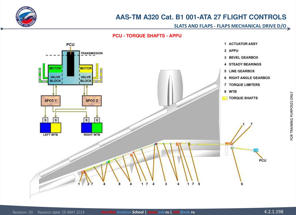
 PCU The Power Control Unit (PCU) incorporates two hydraulic motors, each one controlled by an")


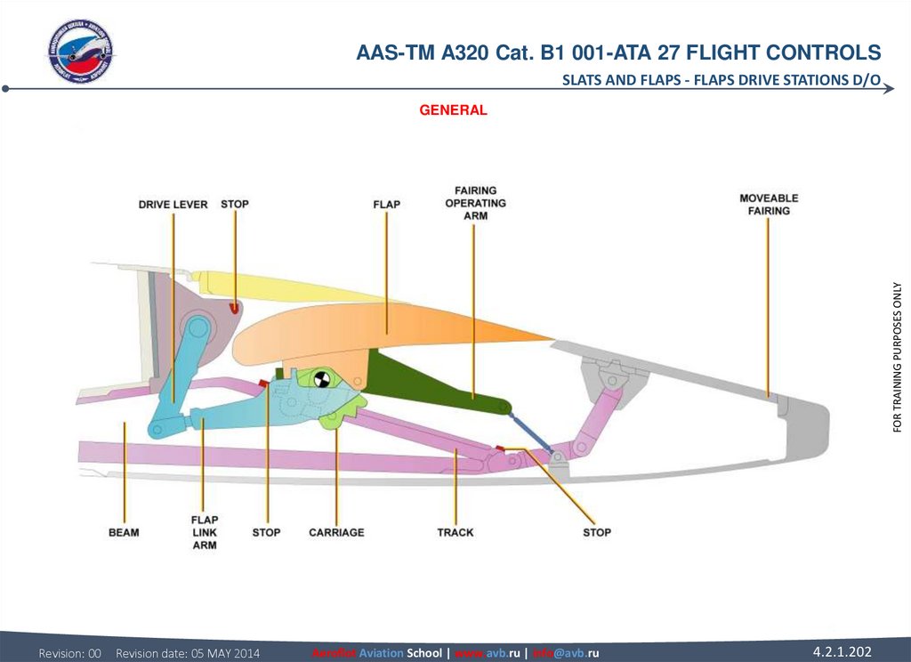

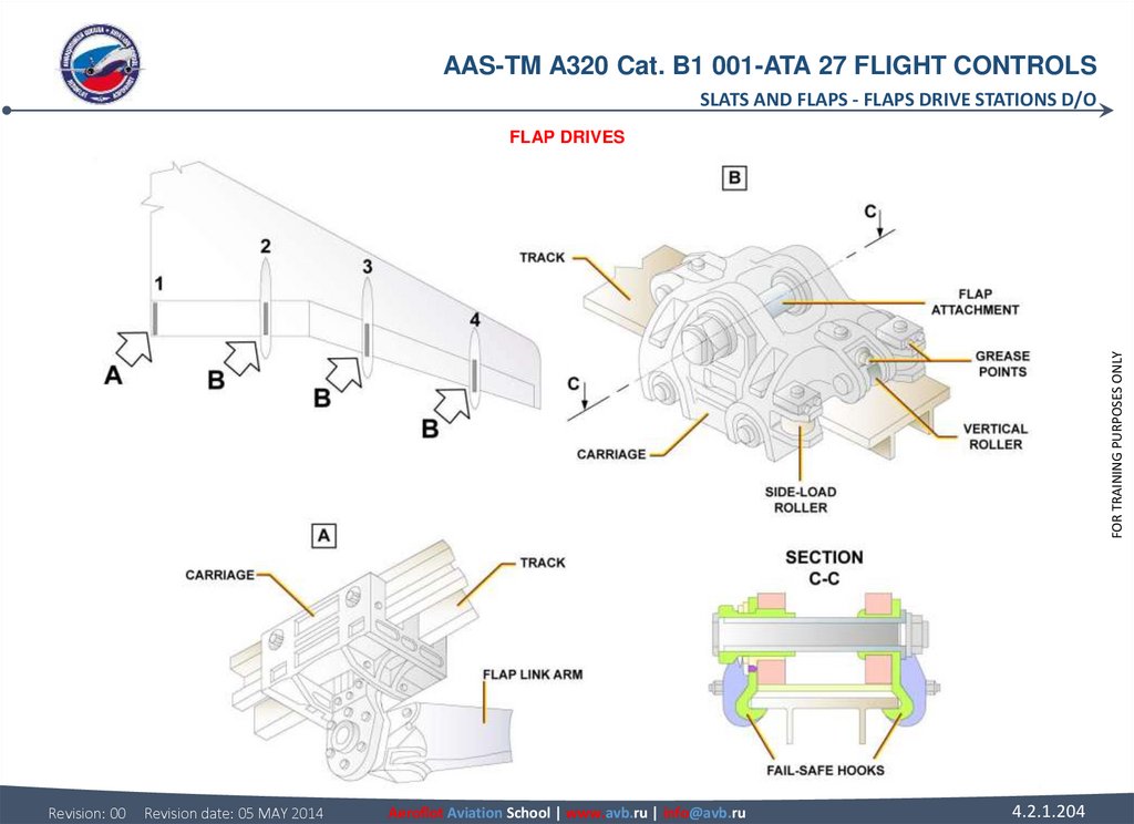


 GENERAL Each flap is supported by carriages that run on tracks extending from the wing rear")

 FLAP DRIVES Six vertical-load and four side-load rollers hold each carriage on its track at")

 FLAP AND TRACK FAIRINGS A flap link arm is attached to the flap bottom surface immediately")

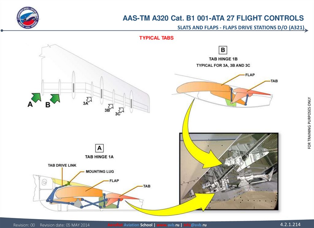
 TYPICAL TABS The inner tab is attached to the rear spar of the flap at track 2 and hinges 1A")
 A321 FIELD TRIP")

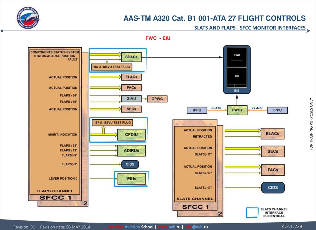
 sends two discrete signals to each channel for a new slat/flap")
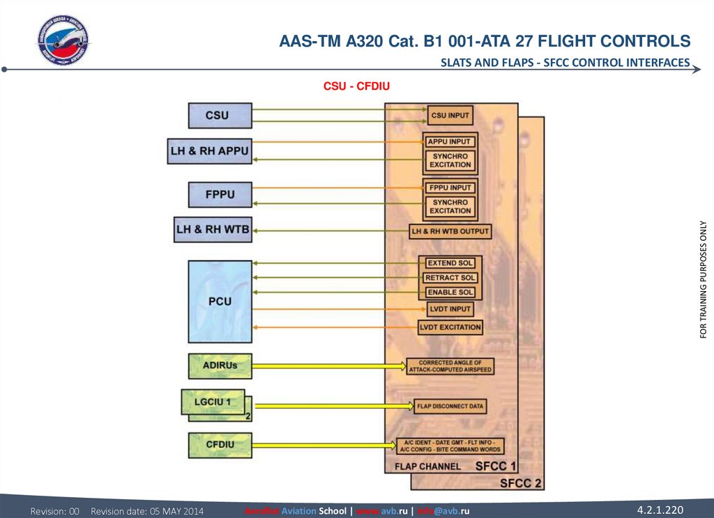
 supply slat/flap position data to the Flight")
 for Angle-Of-Attack (AOA) and static source")


 ELEVATORS The elevator servocontrol position transducer")
 ELAC There are two ELACs (ELAC 1 and 2). Both ELACS are")
 WTB On SLAT or FLAP WTBs, one or two solenoids related to")
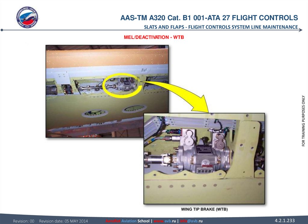

 (continued) Do the")
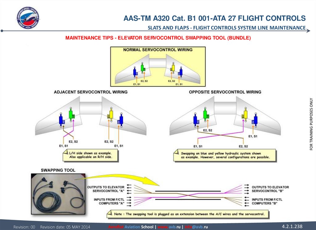
 ELEVATOR SERVOCONTROL SWAPPING TOOL (BUNDLE) When")
 EXTENSION To be unlocked, the servo control actuator must")
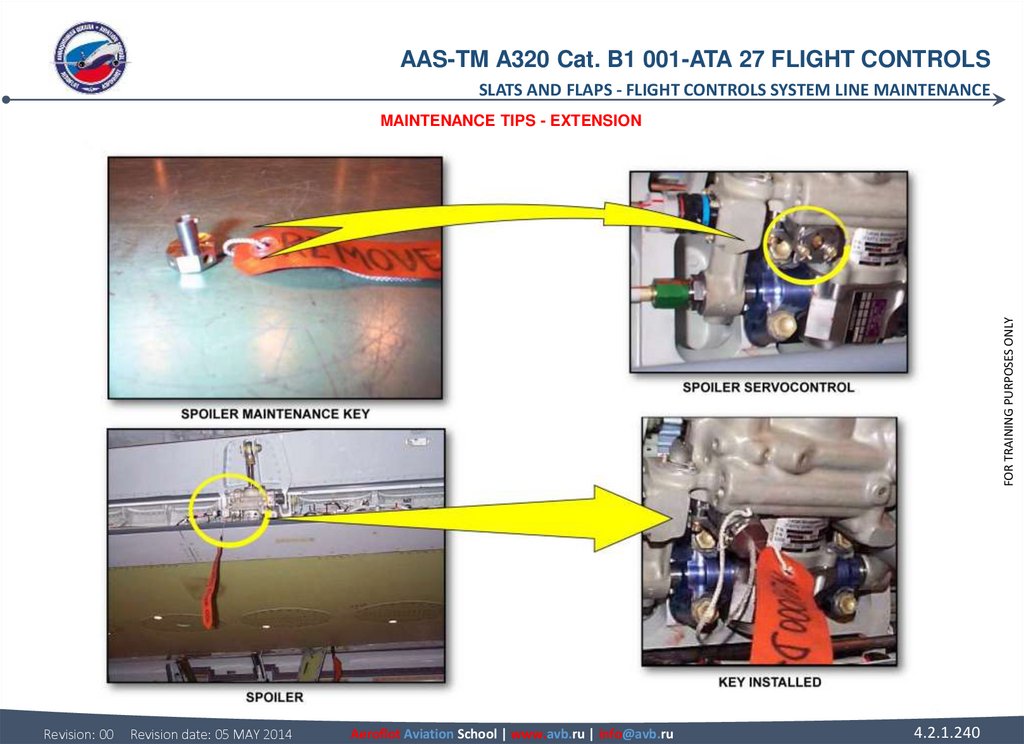
 SAFETY COLLAR INSTALLATION Once the maintenance-unlocking")
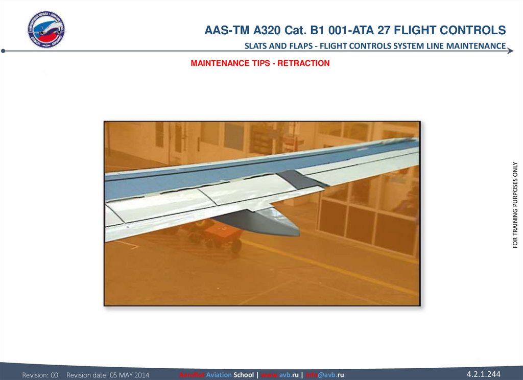
 RETRACTION To retract the spoiler, the Safety Collar must")
 education
 electronics
Similar presentations:


Aircraft type course: airbus a320 category b1
1.
FOR TRAINING PURPOSES ONLYPART 147 – MAINTENANCE TRAINING ORGANIZATION
AIRCRAFT TYPE COURSE:
AIRBUS A320
CATEGORY B1
Revision: 00
Revision date: 05 MAY 2014
Aeroflot Aviation School | www.avb.ru | info@avb.ru
4.2.1.1
2.
AAS-TM A320 Cat. B1 001-ATA 27 FLIGHT CONTROLSTABLE OF CONTENTS
ATA 27 FLIGHT CONTROLS
GENERAL
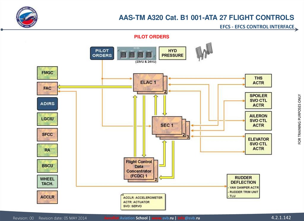
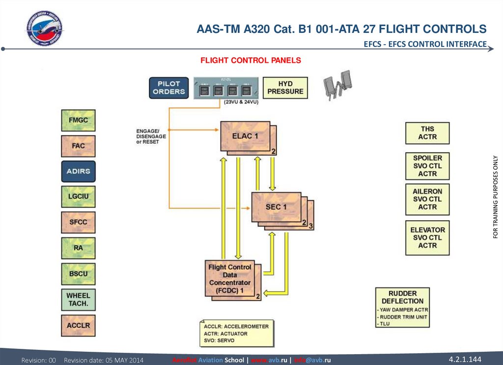
EFCS
Flight Controls System Component Location....................................................
EFCS Control Interface.......................................................................................
Side Stick Description/Operation......................................................................
EFCS Monitor Interface.......................................................................................
Flight Control Laws...........................................................................................
ROLL/YAW
Slats/Flaps Control D/O.......................................................................................
Roll Control Normal D/O...................................................................................
Slats/Flaps Abnormal Locking Operation............................................................
Roll Control Abnormal Operation......................................................................
Slats/Flaps Abnormal Half Speed Operation.......................................................
Yaw Control Normal D/O...................................................................................
Slats Mechanical Drive D/O................................................................................
Yaw Control Abnormal D/O...............................................................................
Flaps Mechanical Drive D/O................................................................................
Aileron Servo Control Operation.......................................................................
Flaps Mechanical Drive D/O (A321)....................................................................
Spoiler Servo Control Operation.......................................................................
Flaps Drive Stations D/O.....................................................................................
Rudder Trim Actuator D/O................................................................................
Flaps Drive Stations D/O (A321).........................................................................
Rudder Servo Control Operation.......................................................................
Flaps Attachment Failure DET Description.........................................................
Rudder Limiter Operation..................................................................................
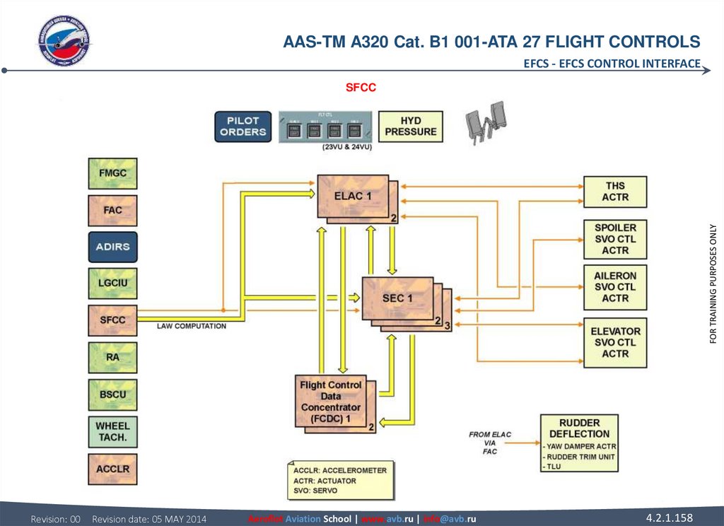
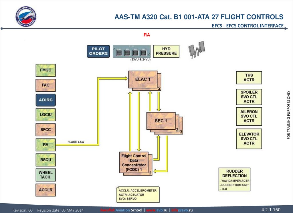
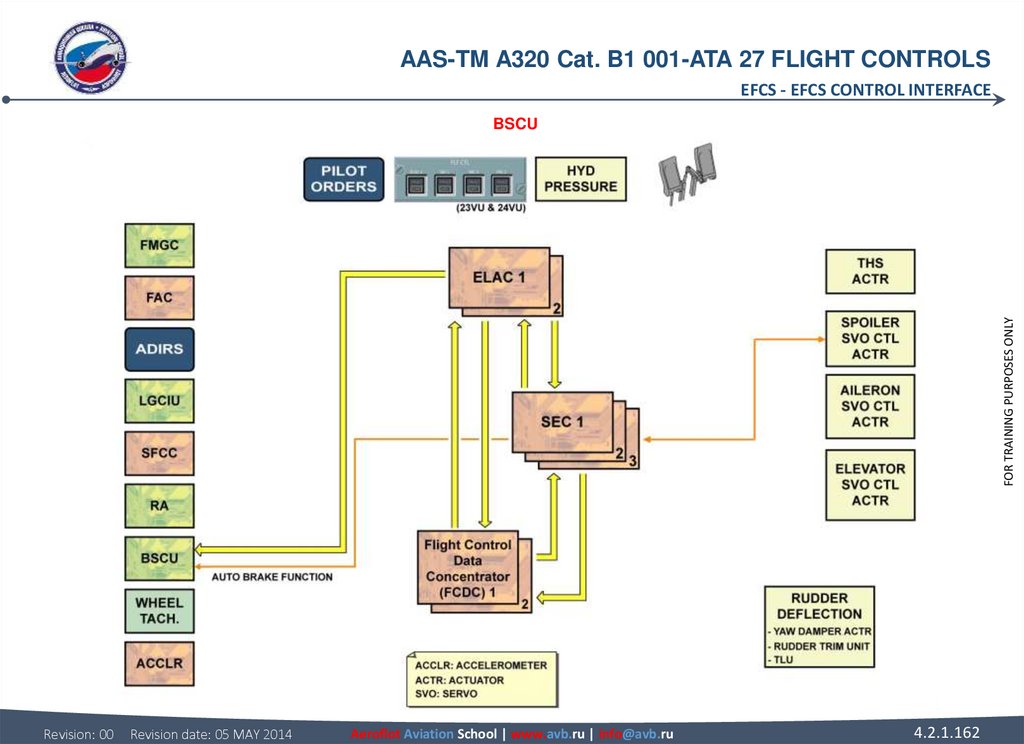
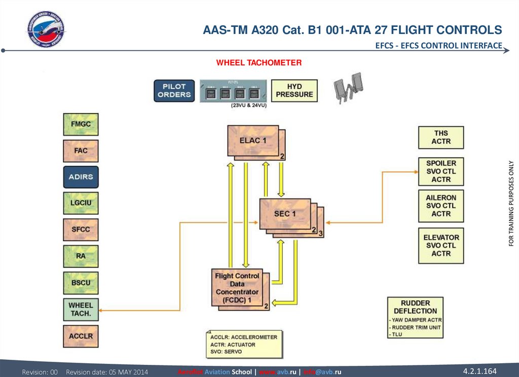
SFCC Control Interfaces.....................................................................................
Yaw Damper Servo Actuator Operation............................................................
SFCC Monitor Interfaces.....................................................................................
Speed Brake & Ground Spoiler D/O.................................................................
Flight Controls System Line Maintenance...........................................................
PITCH
Pitch Control Normal D/O..................................................................................
Pitch Control Abnormal D/O..............................................................................
Elevator Servo Control Operation.....................................................................
THS Actuator Operation....................................................................................
Revision: 00
Revision date: 05 MAY 2014
Aeroflot Aviation School | www.avb.ru | info@avb.ru
4.2.1.2
FOR TRAINING PURPOSES ONLY
SLATS AND FLAPS
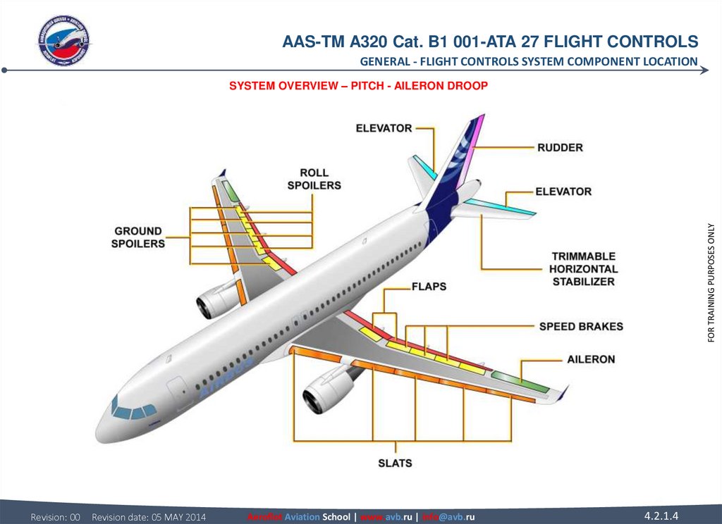
3. GENERAL FLIGHT CONTROLS SYSTEM COMPONENT LOCATION SYSTEM OVERVIEW The control is achieved through the following conventional
AAS-TM A320 Cat. B1 001-ATA 27 FLIGHT CONTROLSGENERAL - FLIGHT CONTROLS SYSTEM COMPONENT LOCATION
GENERAL
FLIGHT CONTROLS SYSTEM COMPONENT LOCATION
PITCH
Two elevators and the Trimmable Horizontal Stabilizer (THS) achieve the pitch control. Elevators are used for short-term activity. The
THS is used for long-term activity.
ROLL
Roll control is achieved by one aileron and spoilers 2 to 5 on each wing, numbered from wing root to wing tip.
YAW
The rudder does the yaw control. The rudder is used during cross wind take-off and landing, and in case of engine failure (thrust
asymmetry). The yaw damper function controls the rudder for Dutch roll damping and turn coordination.
SPEED BRAKES
The speed brake function is used in flight to increase the aircraft drag. Spoilers 2 to 4 are used. Roll orders and speed brake orders
are added with priority given to the roll function.
GROUND SPOILERS
The ground spoiler function is used to destroy the lift during landing and in case of aborted take-off. All spoiler panels are used.
AILERON DROOP
The aileron droop function increases the lift on the part of the wing which has no flaps. The ailerons are deflected downwards when
the flaps are extended.
Revision: 00
Revision date: 05 MAY 2014
Aeroflot Aviation School | www.avb.ru | info@avb.ru
4.2.1.3
FOR TRAINING PURPOSES ONLY
SYSTEM OVERVIEW
The control is achieved through the following conventional surfaces.
4.
AAS-TM A320 Cat. B1 001-ATA 27 FLIGHT CONTROLSGENERAL - FLIGHT CONTROLS SYSTEM COMPONENT LOCATION
FOR TRAINING PURPOSES ONLY
SYSTEM OVERVIEW – PITCH - AILERON DROOP
Revision: 00
Revision date: 05 MAY 2014
Aeroflot Aviation School | www.avb.ru | info@avb.ru
4.2.1.4
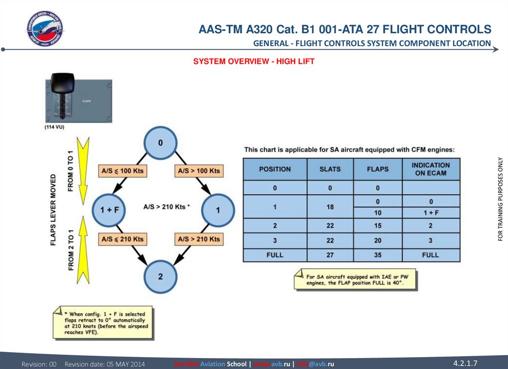
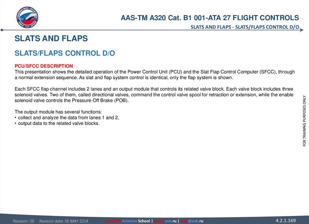
5. FLIGHT CONTROLS SYSTEM COMPONENT LOCATION SYSTEM OVERVIEW (continued) HIGH LIFT Slats and flaps achieve the high lift function.
AAS-TM A320 Cat. B1 001-ATA 27 FLIGHT CONTROLSGENERAL - FLIGHT CONTROLS SYSTEM COMPONENT LOCATION
FLIGHT CONTROLS SYSTEM COMPONENT LOCATION
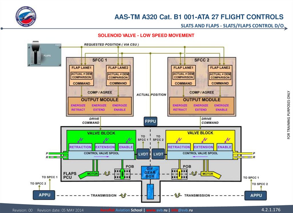
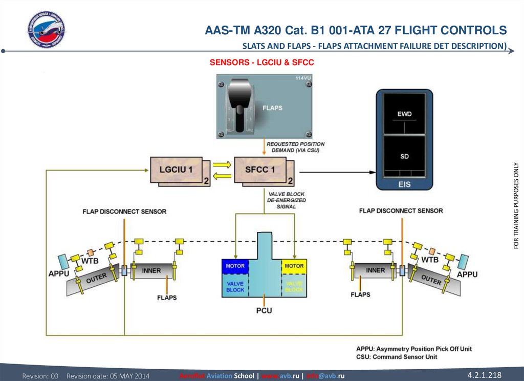
Each motor is powered by a different hydraulic system and has its own valve block and Pressure Off Brake (POB). Valve blocks
control the direction of rotation and the speed of their related PCU output shaft. The POB locks the transmission when the slat and
flap surfaces have reached the selected position or if hydraulic power fails.
Wing Tip Brakes (WTBs) are given in order to stop and lock the system when major failures are detected. They are hydraulically
activated and can only be reset on ground.
Position Pick-Off Units (PPUs) send slat and flap position feedback to the SFCCs and ECAM.
Flap sensors installed between inboard and outboard flaps inhibit further flap operation when a flap attachment failure is detected.
The signal is sent to the SFCCs via the Landing Gear Control and Interface Units (LGCIU). To prevent an aircraft stall, slats cannot
be fully retracted at high angles of attack or low speeds (Alpha/speed lock function).
The FLAPS lever has five positions: 0, 1, 2, 3 and FULL. Two configurations correspond to position 1: Configuration 1 and
Configuration 1+F. These are selected as shown on the graphic. The flaps lever selects simultaneous operation of the slats and flaps.
The five lever positions correspond to the surface positions as shown on the graphic.
Revision: 00
Revision date: 05 MAY 2014
Aeroflot Aviation School | www.avb.ru | info@avb.ru
4.2.1.5
FOR TRAINING PURPOSES ONLY
SYSTEM OVERVIEW (continued)
HIGH LIFT
Slats and flaps achieve the high lift function. There are two flaps, inboard and outboard, and five slats on each wing, numbered from
wing root to wing tip. The A321 has double slotted flaps.
The slats and flaps are electrically controlled and hydraulically operated. Two Slat Flap Control Computers (SFCCs) do the control
and monitoring. Each computer has one slat and one flap channel. The slat and flap systems are similar.
A Power Control Unit (PCU) drives each system with two hydraulic motors coupled to a differential gearbox. Torque shafts and
gearboxes transmit the mechanical power to the actuators, which drive the surfaces.
6.
AAS-TM A320 Cat. B1 001-ATA 27 FLIGHT CONTROLSGENERAL - FLIGHT CONTROLS SYSTEM COMPONENT LOCATION
FOR TRAINING PURPOSES ONLY
SYSTEM OVERVIEW - HIGH LIFT
Revision: 00
Revision date: 05 MAY 2014
Aeroflot Aviation School | www.avb.ru | info@avb.ru
4.2.1.6
7.
AAS-TM A320 Cat. B1 001-ATA 27 FLIGHT CONTROLSGENERAL - FLIGHT CONTROLS SYSTEM COMPONENT LOCATION
FOR TRAINING PURPOSES ONLY
SYSTEM OVERVIEW - HIGH LIFT
Revision: 00
Revision date: 05 MAY 2014
Aeroflot Aviation School | www.avb.ru | info@avb.ru
4.2.1.7
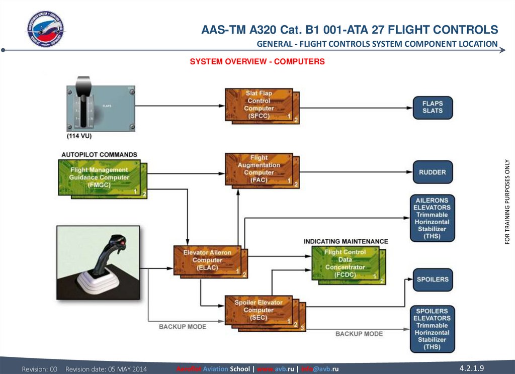
8. FLIGHT CONTROLS SYSTEM COMPONENT LOCATION SYSTEM OVERVIEW (continued) COMPUTERS A computer arrangement permanently controls and
AAS-TM A320 Cat. B1 001-ATA 27 FLIGHT CONTROLSGENERAL - FLIGHT CONTROLS SYSTEM COMPONENT LOCATION
FLIGHT CONTROLS SYSTEM COMPONENT LOCATION
Revision: 00
Revision date: 05 MAY 2014
Aeroflot Aviation School | www.avb.ru | info@avb.ru
FOR TRAINING PURPOSES ONLY
SYSTEM OVERVIEW (continued)
COMPUTERS
A computer arrangement permanently controls and monitors the flight control surfaces, it also records and stores faults.
This arrangement includes:
• 2 Elevator Aileron Computers (ELAC) for pitch and roll control,
• 3 Spoiler Elevator Computers (SEC) for pitch and roll control,
• 2 Flight Augmentation Computers (FAC) for yaw control,
• 2 Flight Control Data Concentrators (FCDC) for indication and maintenance tests,
• 2 Flight Management Guidance Computer (FMGC) for autopilot commands,
• 2 Slat Flap Control Computers (SFCC) for slat and flap control.
4.2.1.8
9.
AAS-TM A320 Cat. B1 001-ATA 27 FLIGHT CONTROLSGENERAL - FLIGHT CONTROLS SYSTEM COMPONENT LOCATION
FOR TRAINING PURPOSES ONLY
SYSTEM OVERVIEW - COMPUTERS
Revision: 00
Revision date: 05 MAY 2014
Aeroflot Aviation School | www.avb.ru | info@avb.ru
4.2.1.9
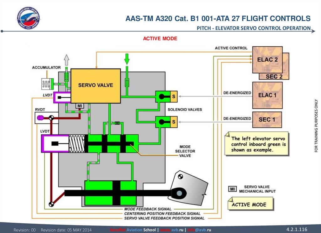
10. FLIGHT CONTROLS SYSTEM COMPONENT LOCATION SYSTEM OVERVIEW (continued) ACTIVE SERVO CONTROLS There are two servo controls for
AAS-TM A320 Cat. B1 001-ATA 27 FLIGHT CONTROLSGENERAL - FLIGHT CONTROLS SYSTEM COMPONENT LOCATION
FLIGHT CONTROLS SYSTEM COMPONENT LOCATION
RECONFIGURATION PRIORITIES
In normal configuration, the following computers do the servoloop control. The arrows indicate the actuation reconfiguration priorities
in case of computer failure or loss of hydraulic circuits.
Revision: 00
Revision date: 05 MAY 2014
Aeroflot Aviation School | www.avb.ru | info@avb.ru
4.2.1.10
FOR TRAINING PURPOSES ONLY
SYSTEM OVERVIEW (continued)
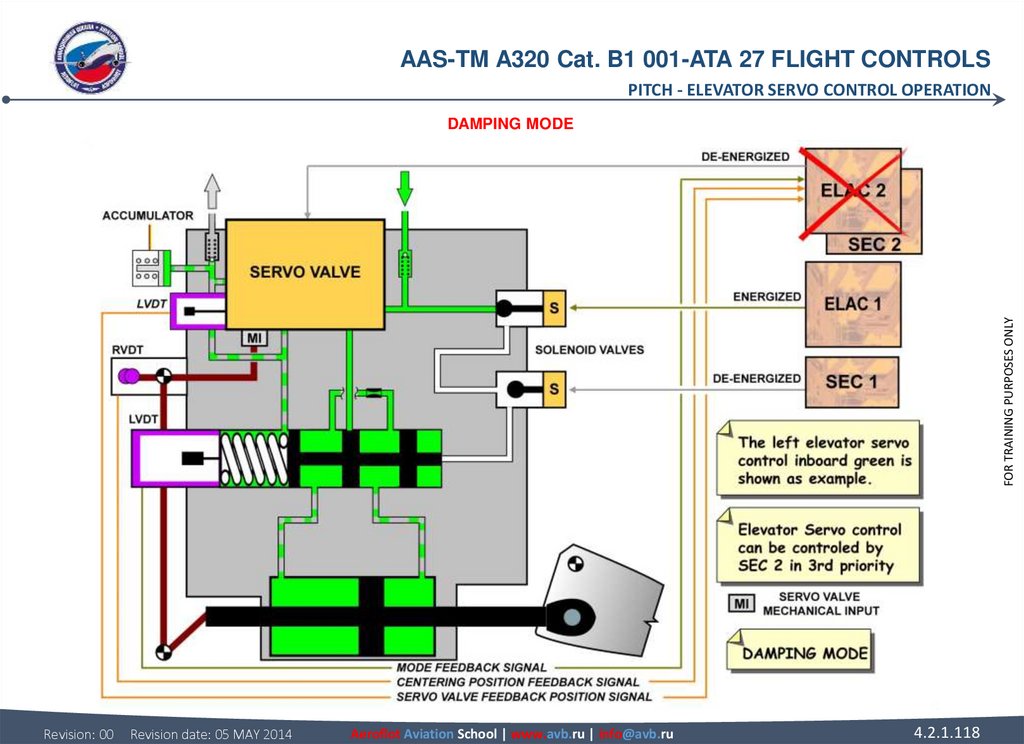
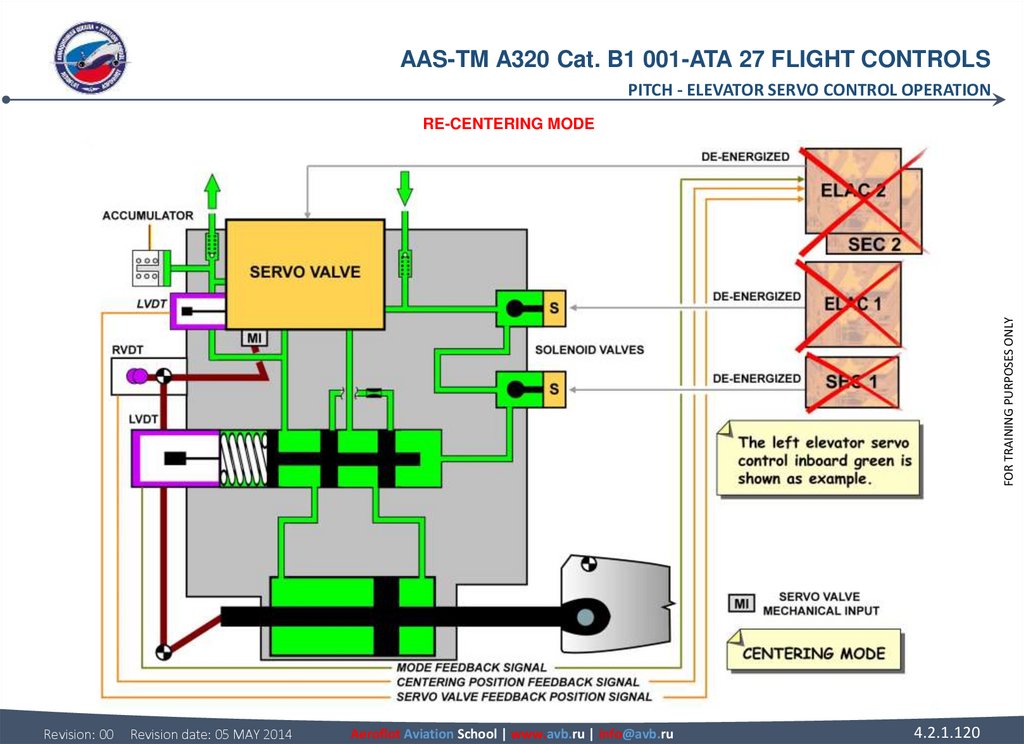
ACTIVE SERVO CONTROLS
There are two servo controls for each aileron, for each elevator and for the yaw damping function. In normal configuration, one servo
control actuates the surface. It is called active servo control. The second, which follows the surface deflection, is in damping mode.
When only manual pitch trim is available, the centering mode is applied to the elevators. The actuators are hydraulically maintained in
neutral position.
11.
AAS-TM A320 Cat. B1 001-ATA 27 FLIGHT CONTROLSGENERAL - FLIGHT CONTROLS SYSTEM COMPONENT LOCATION
FOR TRAINING PURPOSES ONLY
SYSTEM OVERVIEW - ACTIVE SERVO CONTROLS & RECONFIGURATION PRIORITIES
Revision: 00
Revision date: 05 MAY 2014
Aeroflot Aviation School | www.avb.ru | info@avb.ru
4.2.1.11
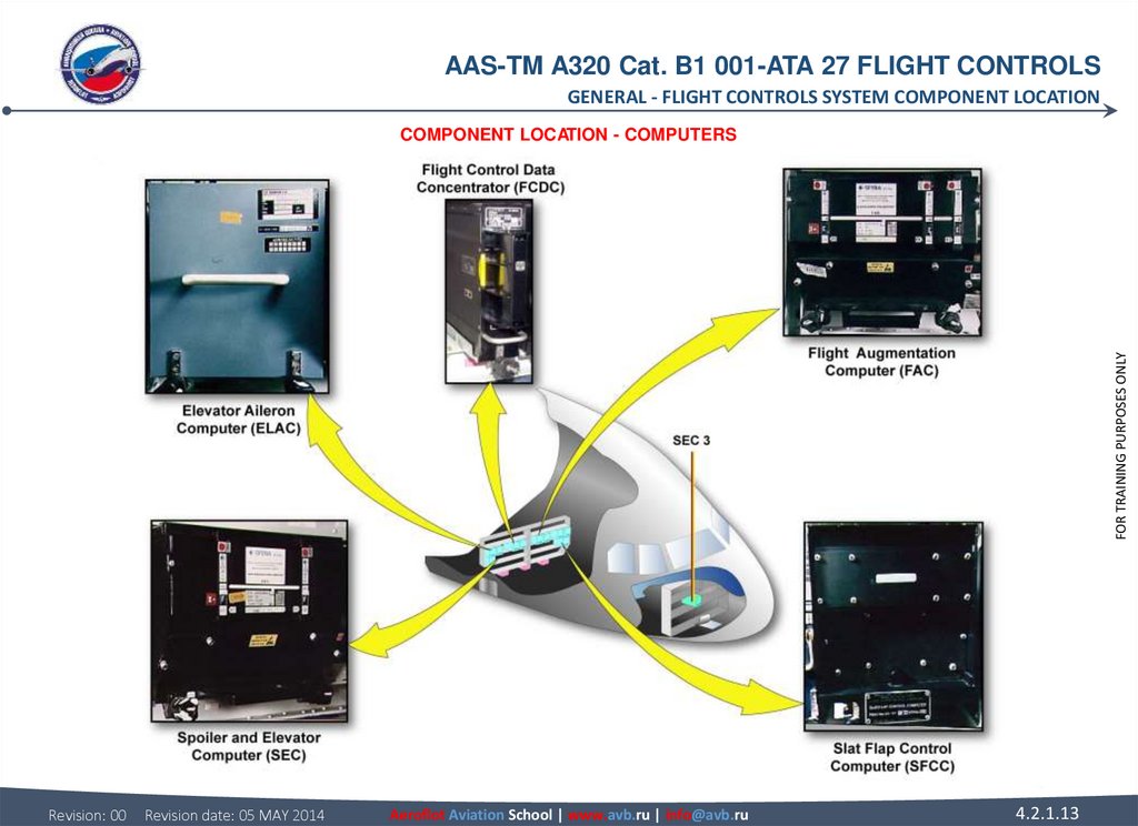
12. FLIGHT CONTROLS SYSTEM COMPONENT LOCATION COMPONENT LOCATION COMPUTERS All the flight control computers are located in the
AAS-TM A320 Cat. B1 001-ATA 27 FLIGHT CONTROLSGENERAL - FLIGHT CONTROLS SYSTEM COMPONENT LOCATION
FLIGHT CONTROLS SYSTEM COMPONENT LOCATION
FOR TRAINING PURPOSES ONLY
COMPONENT LOCATION
COMPUTERS
All the flight control computers are located in the avionics compartment.
Revision: 00
Revision date: 05 MAY 2014
Aeroflot Aviation School | www.avb.ru | info@avb.ru
4.2.1.12
13.
AAS-TM A320 Cat. B1 001-ATA 27 FLIGHT CONTROLSGENERAL - FLIGHT CONTROLS SYSTEM COMPONENT LOCATION
FOR TRAINING PURPOSES ONLY
COMPONENT LOCATION - COMPUTERS
Revision: 00
Revision date: 05 MAY 2014
Aeroflot Aviation School | www.avb.ru | info@avb.ru
4.2.1.13
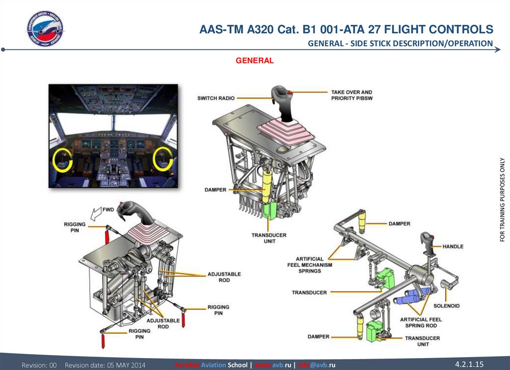
14. SIDE STICK DESCRIPTION/OPERATION GENERAL The main function of the side sticks is to transmit to the Electrical Flight Control
AAS-TM A320 Cat. B1 001-ATA 27 FLIGHT CONTROLSGENERAL - SIDE STICK DESCRIPTION/OPERATION
SIDE STICK DESCRIPTION/OPERATION
Two identical transducer units are associated to each computer, one for roll control, another one for pitch control. A transducer unit
comprises sets of potentiometers driven by a duplicate mechanism and connected to the EFCS computers via connectors. Ring pins
can be installed for adjustment.
WARNING: During handling, make sure that the side stick assembly stays in vertical position. There is a risk of skydrol leakage from
dampers.
Revision: 00
Revision date: 05 MAY 2014
Aeroflot Aviation School | www.avb.ru | info@avb.ru
4.2.1.14
FOR TRAINING PURPOSES ONLY
GENERAL
The main function of the side sticks is to transmit to the Electrical Flight Control System (EFCS) the lateral and longitudinal manual
control orders in the form of electrical signals, depending on the position of the hand grip. It also generate the related artificial feel
loads using spring rods, springs and dampers.
In autopilot mode, a solenoid is energized in order to keep the side sticks in the neutral position. By doing this, the solenoid provides
a higher load level in order to prevent any unwanted switching to the manual control mode, while keeping the possibility to override
the autopilot if required. A thermoformed polycarbonate casing houses the mechanical assembly to prevent the penetration of foreign
matter, which could jam the moving parts.
15.
AAS-TM A320 Cat. B1 001-ATA 27 FLIGHT CONTROLSGENERAL - SIDE STICK DESCRIPTION/OPERATION
FOR TRAINING PURPOSES ONLY
GENERAL
Revision: 00
Revision date: 05 MAY 2014
Aeroflot Aviation School | www.avb.ru | info@avb.ru
4.2.1.15
16. SIDE STICK DESCRIPTION/OPERATION SIDE STICK AND PRIORITY LOGIC Side sticks, one on each lateral console, are used for manual
AAS-TM A320 Cat. B1 001-ATA 27 FLIGHT CONTROLSGENERAL - SIDE STICK DESCRIPTION/OPERATION
SIDE STICK DESCRIPTION/OPERATION
NOTE: In the event of simultaneous inputs on both side sticks (2° deflection off the neutral position in any direction), the two green
SIDE STICK PRIORITY lights, on the glareshield, come on and the "DUAL INPUT" voice message activates.
A pilot can deactivate the other side stick, and take full control by pressing and keeping pressed his takeover P/B. For latching the
priority condition, it is recommended that the takeover P/B be pressed for more than 40 seconds. The takeover pushbutton can then
be released without losing priority. However, a deactivated side stick can be reactivated at any time, by momentarily pressing either
takeover P/B. If both pilots press their takeover P/Bs, the last pilot to press their P/B will have priority.
NOTE: If an autopilot is engaged, any action on a takeover P/B will disengage it.
In a priority situation, a red light will come on, in front of the pilot whose side stick is deactivated. A green light will come on, in front of
the pilot who has taken control, if the other side stick is not in the neutral position (to indicate a potential and unwanted control
demand).
NOTE: If one stick is deactivated on ground, at takeoff thrust application, the takeoff «CONFIG» warning is triggered.
Revision: 00
Revision date: 05 MAY 2014
Aeroflot Aviation School | www.avb.ru | info@avb.ru
4.2.1.16
FOR TRAINING PURPOSES ONLY
SIDE STICK AND PRIORITY LOGIC
Side sticks, one on each lateral console, are used for manual pitch and roll control. They are springloaded to neutral. When the
autopilot is engaged, a solenoid-operated detent locks both side sticks in the neutral position. If the pilot applies a force above a given
threshold (5daN in pitch, 3.5 daN in roll), the autopilot disengages and the side stick unlocks and sends an input to the computers.
The hand grip includes 2 P/Bs: An autopilot disconnect/side stick priority P/B and a push-to-talk button.
Side stick priority logic: When only one pilot operates the side stick, his demand is sent to the computers. When the other pilot
operates his side stick, in the same or opposite direction, both pilot inputs are algebraically added. The addition is limited to singlestick maximum deflection.
17.
AAS-TM A320 Cat. B1 001-ATA 27 FLIGHT CONTROLSGENERAL - SIDE STICK DESCRIPTION/OPERATION
FOR TRAINING PURPOSES ONLY
SIDE STICK AND PRIORITY LOGIC
Revision: 00
Revision date: 05 MAY 2014
Aeroflot Aviation School | www.avb.ru | info@avb.ru
4.2.1.17
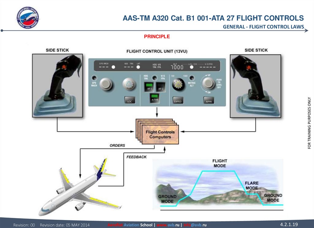
18. FLIGHT CONTROL LAWS PRINCIPLE A side stick or an autopilot sends an electrical signal to the flight control computers for an
AAS-TM A320 Cat. B1 001-ATA 27 FLIGHT CONTROLSGENERAL - FLIGHT CONTROL LAWS
FLIGHT CONTROL LAWS
Normal law is modified depending on the phase of flight. It operates in 3 modes:
• Ground mode: operates on the ground when the aircraft is electrically and hydraulically powered. There is a direct relationship
between the side stick and the control surfaces.
• Flight mode: operates in the air after a gradual transition from ground mode just after lift-off,
• Flare mode: modifies the flight mode to give a conventional "feel" to the landing phase.
In normal LAW, when the aircraft is in flight mode, the control surface deflection is not directly proportional to the side stick deflection.
A side stick deflection gives a rate demand to the flight control computers, which set control surface deflection to meet the rate
demand.
For the same side stick input, the control surface deflections will be large at low speed and small at high speed.
A side stick input is a rate of roll demand in roll and a load factor (g) demand in pitch. Yaw control is conventional.
The response information is fed back to the flight control computers. The computers process this feedback and adjust the control
surface deflection to ensure that the maneuver rate demand is achieved accurately. This means that control surface deflections may
be altered with no change in side stick position.
When in flight mode, if you wish to perform a descending left turn for example, you must set the required attitude and then return the
side stick to neutral. The neutral side stick position requires zero rates of pitch and roll. The flight control computers will maintain the
set attitude until you use the side stick to ask for an attitude change. During the entire maneuver, there is no need for pilot trim inputs.
Revision: 00
Revision date: 05 MAY 2014
Aeroflot Aviation School | www.avb.ru | info@avb.ru
4.2.1.18
FOR TRAINING PURPOSES ONLY
PRINCIPLE
A side stick or an autopilot sends an electrical signal to the flight control computers for an aircraft maneuver. The flight control
computers process the demand and send it to the control surfaces. The processing uses pre-set limitations and instructions called
LAWS. In normal law, regardless of the pilots' input, the computers will prevent excessive maneuvers and make sure the safe
envelope is not exceeded in pitch and roll axes. The rudder control is designed as on a conventional aircraft.
19.
AAS-TM A320 Cat. B1 001-ATA 27 FLIGHT CONTROLSGENERAL - FLIGHT CONTROL LAWS
FOR TRAINING PURPOSES ONLY
PRINCIPLE
Revision: 00
Revision date: 05 MAY 2014
Aeroflot Aviation School | www.avb.ru | info@avb.ru
4.2.1.19
20.
AAS-TM A320 Cat. B1 001-ATA 27 FLIGHT CONTROLSGENERAL - FLIGHT CONTROL LAWS
FOR TRAINING PURPOSES ONLY
PRINCIPLE
Revision: 00
Revision date: 05 MAY 2014
Aeroflot Aviation School | www.avb.ru | info@avb.ru
4.2.1.20
21. FLIGHT CONTROL LAWS NORMAL LAW Normal law provides a number of airborne pitch protections. They are: • Load factor limitation,
AAS-TM A320 Cat. B1 001-ATA 27 FLIGHT CONTROLSGENERAL - FLIGHT CONTROL LAWS
FLIGHT CONTROL LAWS
FOR TRAINING PURPOSES ONLY
NORMAL LAW
Normal law provides a number of airborne pitch protections.
They are:
• Load factor limitation,
• Pitch attitude protection,
• High angle of attack protection,
• High speed protection.
In lateral control, there is only one protection, which is for bank angle.
NOTE: Turn co-ordination and "Dutch roll" damping are automatically provided in normal law.
Pilot inputs on the rudder pedals are not required.
LOAD FACTOR LIMITATION
Load factor limitation prevents structural overstress by a limitation of the control surface deflections through the flight control
computers. Full side stick movement is always available.
The load factor is automatically limited to:
• (+) 2.5 g to (-) 1 g in clean configuration,
• (+) 2 g to 0 g in other configurations.
Revision: 00
Revision date: 05 MAY 2014
Aeroflot Aviation School | www.avb.ru | info@avb.ru
4.2.1.21
22.
AAS-TM A320 Cat. B1 001-ATA 27 FLIGHT CONTROLSGENERAL - FLIGHT CONTROL LAWS
FOR TRAINING PURPOSES ONLY
NORMAL LAW - LOAD FACTOR LIMITATION
Revision: 00
Revision date: 05 MAY 2014
Aeroflot Aviation School | www.avb.ru | info@avb.ru
4.2.1.22
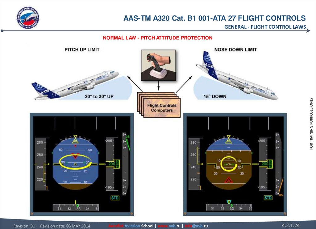
23. FLIGHT CONTROL LAWS NORMAL LAW (continued) PITCH ATTITUDE PROTECTION If the aircraft reaches the pitch attitude protection nose
AAS-TM A320 Cat. B1 001-ATA 27 FLIGHT CONTROLSGENERAL - FLIGHT CONTROL LAWS
FLIGHT CONTROL LAWS
FOR TRAINING PURPOSES ONLY
NORMAL LAW (continued)
PITCH ATTITUDE PROTECTION
If the aircraft reaches the pitch attitude protection nose up limits, then the flight control computers will override pilot demands and
keep the aircraft within the safe flight limits.
The pitch attitude protection limits are shown as small green dashes on the Primary Flight Display (PFD).
The pitch up values are different depending on the aircraft configuration and speed between 30 and 20 degrees up.
The nose down limit is 15 degrees.
Revision: 00
Revision date: 05 MAY 2014
Aeroflot Aviation School | www.avb.ru | info@avb.ru
4.2.1.23
24.
AAS-TM A320 Cat. B1 001-ATA 27 FLIGHT CONTROLSGENERAL - FLIGHT CONTROL LAWS
FOR TRAINING PURPOSES ONLY
NORMAL LAW - PITCH ATTITUDE PROTECTION
Revision: 00
Revision date: 05 MAY 2014
Aeroflot Aviation School | www.avb.ru | info@avb.ru
4.2.1.24
25. FLIGHT CONTROL LAWS NORMAL LAW (continued) HIGH ANGLE OF ATTACK PROTECTION The high Angle Of Attack (AOA) protection is
AAS-TM A320 Cat. B1 001-ATA 27 FLIGHT CONTROLSGENERAL - FLIGHT CONTROL LAWS
FLIGHT CONTROL LAWS
NOTE: V PROT and V MAX may be different because they are G-load sensitive.
When the speed decreases, V PROT reaches VLS, which is the lowest speed that can be selected with the autothrust engaged.
A low energy warning, repeated every 5 seconds, indicates to the pilot that the aircraft energy becomes lower than a threshold. Under
this threshold, the thrust must be increased to recover a positive flight path angle through pitch control.
The low energy warning is available in the following conditions:
• Above 100 ft RA and
• Below 2,000 ft RA and
• In conf 2, 3, FULL and
• Not in TOGA, ...
Revision: 00
Revision date: 05 MAY 2014
Aeroflot Aviation School | www.avb.ru | info@avb.ru
4.2.1.25
FOR TRAINING PURPOSES ONLY
NORMAL LAW (continued)
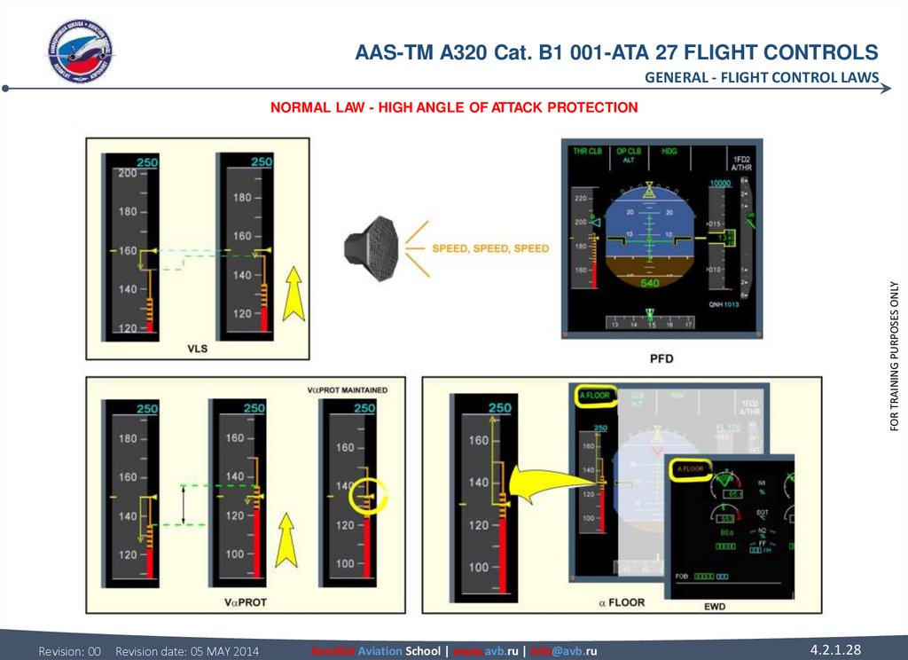
HIGH ANGLE OF ATTACK PROTECTION
The high Angle Of Attack (AOA) protection is designed to prevent a stalling of the aircraft and to ensure optimum performance in
extreme maneuvers, for example windshear or Enhanced Ground Proximity Warning System (EGPWS) warning recovery.
This protection takes priority on all others. This protection displays information on the side of the PFD speed scale.
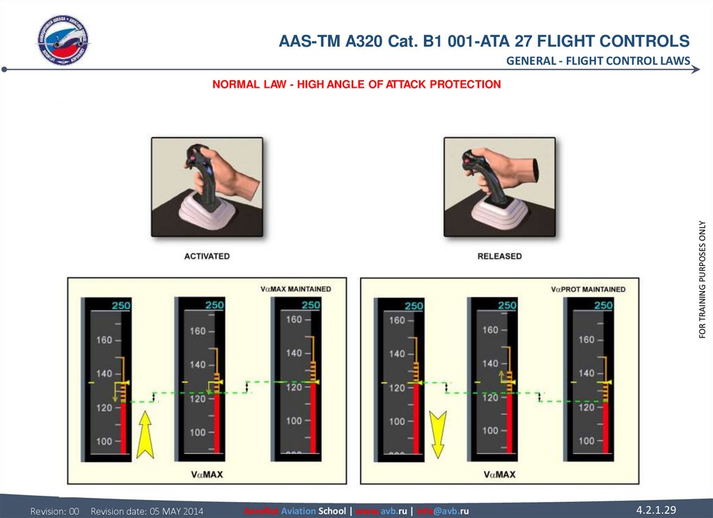
Under normal law, when the angle of attack becomes more than PROT, the system changes from normal mode to protection mode:
The side sticks controls directly an angle of attack.
26. NORMAL LAW (continued) HIGH ANGLE OF ATTACK PROTECTION (continued) With autothrust inoperative or not engaged, the speed can
AAS-TM A320 Cat. B1 001-ATA 27 FLIGHT CONTROLSGENERAL - FLIGHT CONTROL LAWS
NORMAL LAW (continued)
HIGH ANGLE OF ATTACK PROTECTION (continued)
With autothrust inoperative or not engaged, the speed can reduce to the first level of AOA protection, V PROT, which is shown at the
top of the amber / black band (barber pole).
If engaged, the autopilot will disconnect. Nose up pitch trim is inhibited below V PROT.
A/THR is automatically activated and commands TOGA thrust when the aircraft angle of attack is above a pre-determined threshold.
This is indicated by an "A FLOOR" indication on the Flight Mode Annunciator (FMA) and also on the Engine Warning Display (EWD).
If the pilots override V PROT with the side stick, the speed can reduce to V MAX.
In normal law, the flight control computers will maintain V MAX, even if a pilot holds a side stick fully aft.
In this protection range, the normal law demand is modified and side stick input is an AOA demand, instead of a load factor demand.
If the pilot releases the side stick at V MAX, the speed will return to V PROT and will be maintained.
Revision: 00
Revision date: 05 MAY 2014
Aeroflot Aviation School | www.avb.ru | info@avb.ru
4.2.1.26
FOR TRAINING PURPOSES ONLY
The flight control computers will maintain V PROT if the side stick is released.
The floor protection is usually available from lift-off down to 100 ft RA.
27.
AAS-TM A320 Cat. B1 001-ATA 27 FLIGHT CONTROLSGENERAL - FLIGHT CONTROL LAWS
FOR TRAINING PURPOSES ONLY
NORMAL LAW - HIGH ANGLE OF ATTACK PROTECTION
Revision: 00
Revision date: 05 MAY 2014
Aeroflot Aviation School | www.avb.ru | info@avb.ru
4.2.1.27
28.
AAS-TM A320 Cat. B1 001-ATA 27 FLIGHT CONTROLSGENERAL - FLIGHT CONTROL LAWS
FOR TRAINING PURPOSES ONLY
NORMAL LAW - HIGH ANGLE OF ATTACK PROTECTION
Revision: 00
Revision date: 05 MAY 2014
Aeroflot Aviation School | www.avb.ru | info@avb.ru
4.2.1.28
29.
AAS-TM A320 Cat. B1 001-ATA 27 FLIGHT CONTROLSGENERAL - FLIGHT CONTROL LAWS
FOR TRAINING PURPOSES ONLY
NORMAL LAW - HIGH ANGLE OF ATTACK PROTECTION
Revision: 00
Revision date: 05 MAY 2014
Aeroflot Aviation School | www.avb.ru | info@avb.ru
4.2.1.29
30. FLIGHT CONTROL LAWS NORMAL LAW (continued) HIGH SPEED PROTECTION The high speed protection is designed to prevent the aircraft
AAS-TM A320 Cat. B1 001-ATA 27 FLIGHT CONTROLSGENERAL - FLIGHT CONTROL LAWS
FLIGHT CONTROL LAWS
NORMAL LAW (continued)
HIGH SPEED PROTECTION
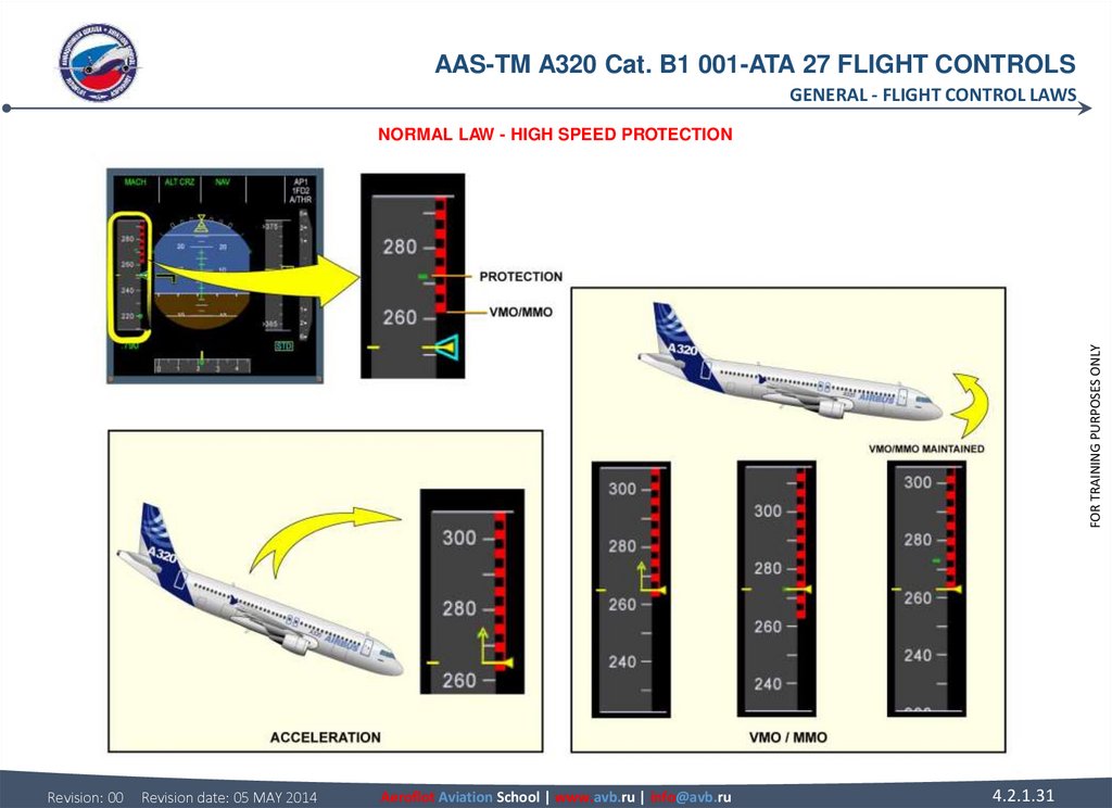
The high speed protection is designed to prevent the aircraft from exceeding maximum speed.
These protection limits are displayed on the PFD speed scale. VMO/MMO is shown at the bottom of the red/black barber pole. Green
dashes indicate the speed at which the protection is activated. When the airspeed/Mach increases above VMO/MMO, an overspeed
ECAM warning is triggered (refer to Autoflight chapter).
FOR TRAINING PURPOSES ONLY
If the airspeed/Mach increases to the protection activation speed:
• the autopilot disengages and,
• the flight control computers send a pitch up command to the control surfaces to prevent more acceleration.
The side stick authority is reduced, but the flight control computers will permit this speed to be exceeded momentarily for
maneuvering if necessary.
With stick released, the speed will return to VMO/MMO.
Revision: 00
Revision date: 05 MAY 2014
Aeroflot Aviation School | www.avb.ru | info@avb.ru
4.2.1.30
31.
AAS-TM A320 Cat. B1 001-ATA 27 FLIGHT CONTROLSGENERAL - FLIGHT CONTROL LAWS
FOR TRAINING PURPOSES ONLY
NORMAL LAW - HIGH SPEED PROTECTION
Revision: 00
Revision date: 05 MAY 2014
Aeroflot Aviation School | www.avb.ru | info@avb.ru
4.2.1.31
32. FLIGHT CONTROL LAWS NORMAL LAW (continued) BANK ANGLE PROTECTION Under normal law, bank angle protection limits the angle of
AAS-TM A320 Cat. B1 001-ATA 27 FLIGHT CONTROLSGENERAL - FLIGHT CONTROL LAWS
NORMAL LAW (continued)
BANK ANGLE PROTECTION
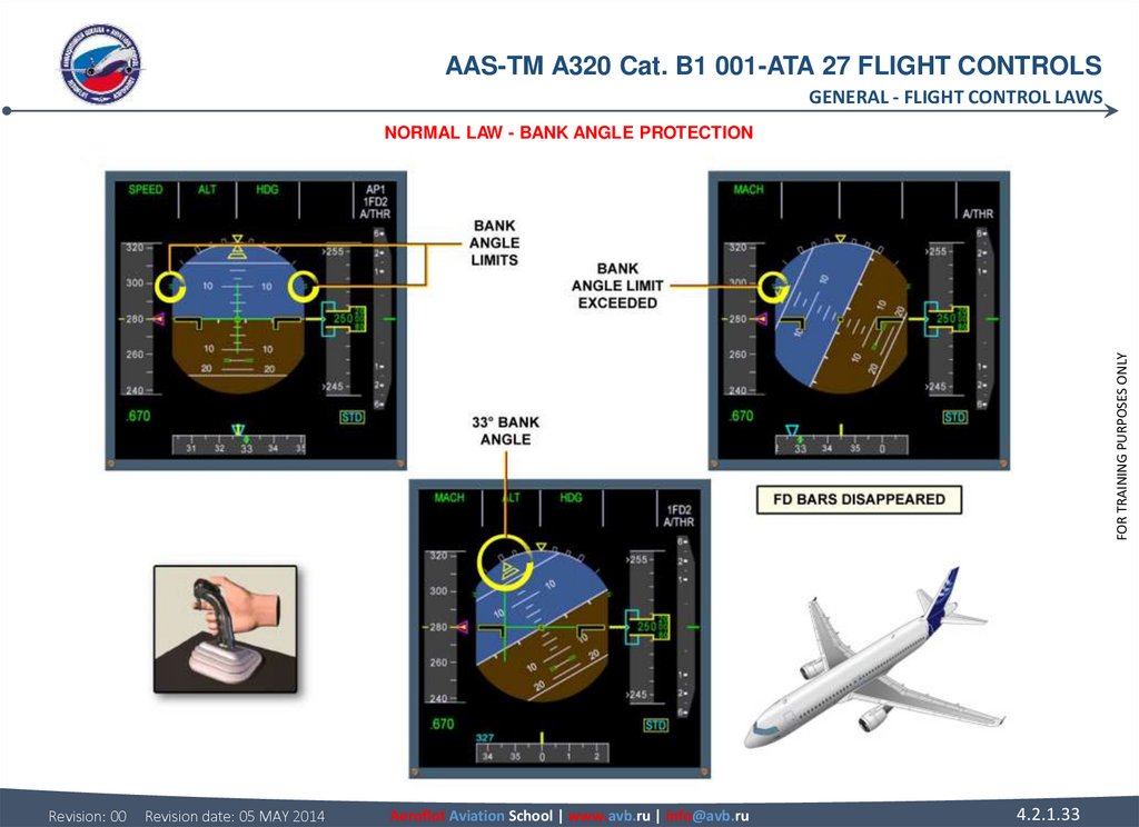
Under normal law, bank angle protection limits the angle of bank to 67 degrees, shown by green dashes on the PFD.
If the pilot holds full lateral side stick, the angle of bank will increase and maintain 67 degrees.
The Flight Director (FD) on the PFD will disappear if the angle of bank exceeds 45 degrees.
If the side stick is released at any time when the bank angle exceeds 33 degrees, the aircraft will return to and maintain a 33 degrees
bank angle.
The FD will be displayed again on the PFD when the angle of bank reduces to less than 40 degrees.
The autotrim is inhibited above 33 degrees.
With the angle of attack protections active:
• The bank angle is limited to 45 degrees and no more.
With the high speed protection active:
• The system maintains a positive spiral stability to 0 degree bank angle, so that if the side stick is released, the aircraft returns to
wing level.
The bank angle limit is also reduced from 67 to 40 degrees.
Revision: 00
Revision date: 05 MAY 2014
Aeroflot Aviation School | www.avb.ru | info@avb.ru
4.2.1.32
FOR TRAINING PURPOSES ONLY
FLIGHT CONTROL LAWS
33.
AAS-TM A320 Cat. B1 001-ATA 27 FLIGHT CONTROLSGENERAL - FLIGHT CONTROL LAWS
FOR TRAINING PURPOSES ONLY
NORMAL LAW - BANK ANGLE PROTECTION
Revision: 00
Revision date: 05 MAY 2014
Aeroflot Aviation School | www.avb.ru | info@avb.ru
4.2.1.33
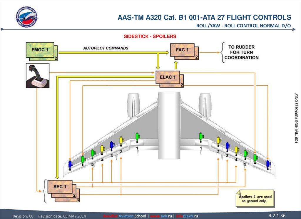
34. ROLL/YAW ROLL CONTROL NORMAL D/O SIDESTICK The sidestick sends electrical orders to the ELevator Aileron Computers (ELACs) and
AAS-TM A320 Cat. B1 001-ATA 27 FLIGHT CONTROLSROLL/YAW - ROLL CONTROL NORMAL D/O
ROLL/YAW
ROLL CONTROL NORMAL D/O
ELAC
There are two ELACs: ELAC 1 normally controls the ailerons, with ELAC 2 as back-up. In case of failure of ELAC 1, ELAC 2 will
automatically take control.
SEC
Using orders coming from the ELACs, each SEC sends orders to one or two pairs of spoilers, without back-up.
FAC
Flight Augmentation Computer (FAC) 1, with FAC 2 as back-up, transmits turn coordination orders for the rudder.
FMGC
When the autopilot is engaged, the Flight Management and Guidance Computer (FMGC) sends roll commands to the ELACs and the
FACs, and to the SECs through the ELACs via ARINC 429 data buses.
AILERONS
There are two electrically-controlled hydraulic actuators per aileron, one in active mode and the other in damping mode. The left blue
and right green actuators are controlled by ELAC 1 and the other two actuators by ELAC 2. All aileron actuators revert to damping
mode in case of a double ELAC failure or green and blue hydraulic low pressure.
Revision: 00
Revision date: 05 MAY 2014
Aeroflot Aviation School | www.avb.ru | info@avb.ru
4.2.1.34
FOR TRAINING PURPOSES ONLY
SIDESTICK
The sidestick sends electrical orders to the ELevator Aileron Computers (ELACs) and Spoiler Elevator Computers (SECs).
35. SPOILERS Each spoiler is powered by one hydraulic actuator. Surfaces are automatically retracted if a fault is detected by the
AAS-TM A320 Cat. B1 001-ATA 27 FLIGHT CONTROLSROLL/YAW - ROLL CONTROL NORMAL D/O
SPOILERS
Each spoiler is powered by one hydraulic actuator. Surfaces are automatically retracted if a fault is detected by the monitoring system
or if there is no electrical supply.
In case of loss of hydraulic power supply:
• if retracted, the surface remains retracted,
• if not retracted, the surface will maintain existing deflection to the zero hinge moment position or less if pushed down by
aerodynamics.
FOR TRAINING PURPOSES ONLY
NOTE: Spoilers 1 are not used for roll control.
Revision: 00
Revision date: 05 MAY 2014
Aeroflot Aviation School | www.avb.ru | info@avb.ru
4.2.1.35
36.
AAS-TM A320 Cat. B1 001-ATA 27 FLIGHT CONTROLSROLL/YAW - ROLL CONTROL NORMAL D/O
FOR TRAINING PURPOSES ONLY
SIDESTICK - SPOILERS
Revision: 00
Revision date: 05 MAY 2014
Aeroflot Aviation School | www.avb.ru | info@avb.ru
4.2.1.36
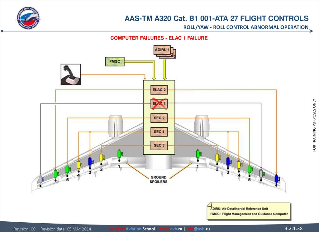
37. ROLL CONTROL ABNORMAL OPERATION COMPUTER FAILURES A computer failure can engage a lateral abnormal configuration. ELAC 1
AAS-TM A320 Cat. B1 001-ATA 27 FLIGHT CONTROLSROLL/YAW - ROLL CONTROL ABNORMAL OPERATION
ROLL CONTROL ABNORMAL OPERATION
COMPUTER FAILURES
A computer failure can engage a lateral abnormal configuration.
FOR TRAINING PURPOSES ONLY
ELAC 1 FAILURE
The loss of ELevator Aileron Computer (ELAC) 1 leads to select ELAC 2 active. ELAC 2 computes the lateral orders in normal law
and transmits them to the Spoiler Elevator Computer (SEC) for the roll spoiler.
Revision: 00
Revision date: 05 MAY 2014
Aeroflot Aviation School | www.avb.ru | info@avb.ru
4.2.1.37
38.
AAS-TM A320 Cat. B1 001-ATA 27 FLIGHT CONTROLSROLL/YAW - ROLL CONTROL ABNORMAL OPERATION
FOR TRAINING PURPOSES ONLY
COMPUTER FAILURES - ELAC 1 FAILURE
Revision: 00
Revision date: 05 MAY 2014
Aeroflot Aviation School | www.avb.ru | info@avb.ru
4.2.1.38
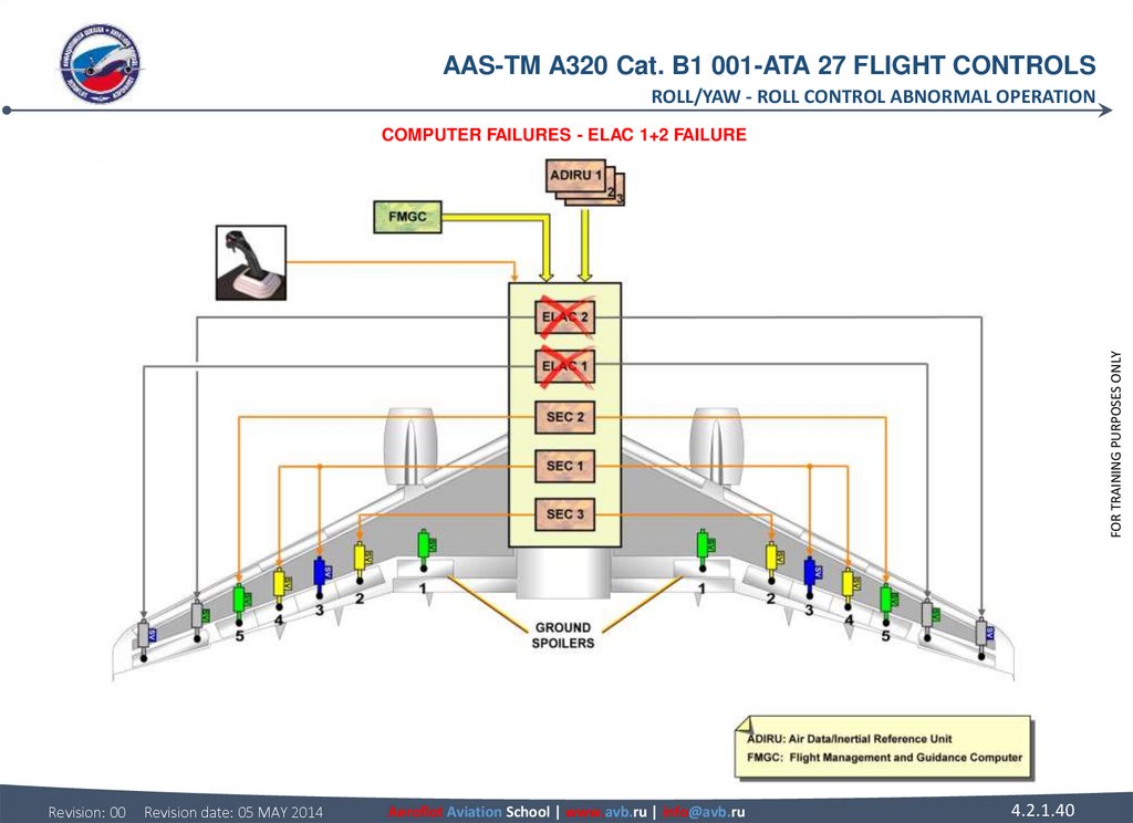
39. ROLL CONTROL ABNORMAL OPERATION COMPUTER FAILURES (continued) ELAC 1+2 FAILURE In case of loss of both ELACs only spoilers are
AAS-TM A320 Cat. B1 001-ATA 27 FLIGHT CONTROLSROLL/YAW - ROLL CONTROL ABNORMAL OPERATION
ROLL CONTROL ABNORMAL OPERATION
FOR TRAINING PURPOSES ONLY
COMPUTER FAILURES (continued)
ELAC 1+2 FAILURE
In case of loss of both ELACs only spoilers are available.
The SECs control the roll in direct law and the yaw damping function normal law is lost.
Revision: 00
Revision date: 05 MAY 2014
Aeroflot Aviation School | www.avb.ru | info@avb.ru
4.2.1.39
40.
AAS-TM A320 Cat. B1 001-ATA 27 FLIGHT CONTROLSROLL/YAW - ROLL CONTROL ABNORMAL OPERATION
FOR TRAINING PURPOSES ONLY
COMPUTER FAILURES - ELAC 1+2 FAILURE
Revision: 00
Revision date: 05 MAY 2014
Aeroflot Aviation School | www.avb.ru | info@avb.ru
4.2.1.40
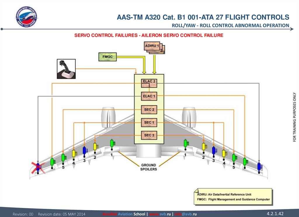
41. ROLL CONTROL ABNORMAL OPERATION SERVO CONTROL FAILURES AILERON SERVO CONTROL FAILURE In case of failure of one aileron servo
AAS-TM A320 Cat. B1 001-ATA 27 FLIGHT CONTROLSROLL/YAW - ROLL CONTROL ABNORMAL OPERATION
ROLL CONTROL ABNORMAL OPERATION
FOR TRAINING PURPOSES ONLY
SERVO CONTROL FAILURES
AILERON SERVO CONTROL FAILURE
In case of failure of one aileron servo control, the second one takes over and is controlled by the other ELAC. In this example, ELAC
1 still computes the orders and ELAC 2 is in slave mode.
Revision: 00
Revision date: 05 MAY 2014
Aeroflot Aviation School | www.avb.ru | info@avb.ru
4.2.1.41
42.
AAS-TM A320 Cat. B1 001-ATA 27 FLIGHT CONTROLSROLL/YAW - ROLL CONTROL ABNORMAL OPERATION
FOR TRAINING PURPOSES ONLY
SERVO CONTROL FAILURES - AILERON SERVO CONTROL FAILURE
Revision: 00
Revision date: 05 MAY 2014
Aeroflot Aviation School | www.avb.ru | info@avb.ru
4.2.1.42
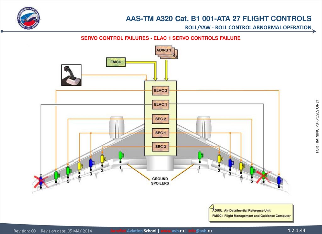
43. ROLL CONTROL ABNORMAL OPERATION SERVO CONTROL FAILURES (continued) ELAC 1 SERVO CONTROLS FAILURE In case of failure of both
AAS-TM A320 Cat. B1 001-ATA 27 FLIGHT CONTROLSROLL/YAW - ROLL CONTROL ABNORMAL OPERATION
ROLL CONTROL ABNORMAL OPERATION
FOR TRAINING PURPOSES ONLY
SERVO CONTROL FAILURES (continued)
ELAC 1 SERVO CONTROLS FAILURE
In case of failure of both ELAC 1 servo controls, then ELAC 2 does the computation and controls its servo controls.
Revision: 00
Revision date: 05 MAY 2014
Aeroflot Aviation School | www.avb.ru | info@avb.ru
4.2.1.43
44.
AAS-TM A320 Cat. B1 001-ATA 27 FLIGHT CONTROLSROLL/YAW - ROLL CONTROL ABNORMAL OPERATION
FOR TRAINING PURPOSES ONLY
SERVO CONTROL FAILURES - ELAC 1 SERVO CONTROLS FAILURE
Revision: 00
Revision date: 05 MAY 2014
Aeroflot Aviation School | www.avb.ru | info@avb.ru
4.2.1.44
45. ROLL CONTROL ABNORMAL OPERATION SERVO CONTROL FAILURES (continued) FAILURES ON THE SAME AILERON In case of failure of both
AAS-TM A320 Cat. B1 001-ATA 27 FLIGHT CONTROLSROLL/YAW - ROLL CONTROL ABNORMAL OPERATION
ROLL CONTROL ABNORMAL OPERATION
FOR TRAINING PURPOSES ONLY
SERVO CONTROL FAILURES (continued)
FAILURES ON THE SAME AILERON
In case of failure of both servo controls of the same aileron, the other aileron is still operated.
Revision: 00
Revision date: 05 MAY 2014
Aeroflot Aviation School | www.avb.ru | info@avb.ru
4.2.1.45
46.
AAS-TM A320 Cat. B1 001-ATA 27 FLIGHT CONTROLSROLL/YAW - ROLL CONTROL ABNORMAL OPERATION
FOR TRAINING PURPOSES ONLY
SERVO CONTROL FAILURES - FAILURES ON THE SAME AILERON
Revision: 00
Revision date: 05 MAY 2014
Aeroflot Aviation School | www.avb.ru | info@avb.ru
4.2.1.46
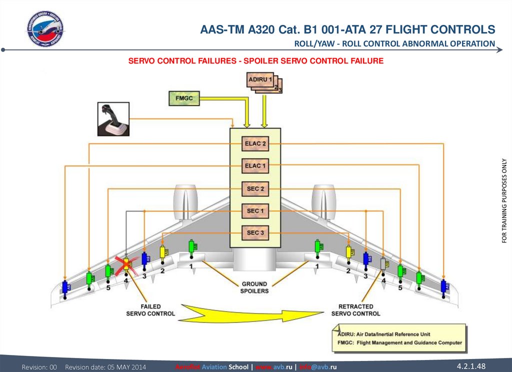
47. ROLL CONTROL ABNORMAL OPERATION SERVO CONTROL FAILURES (continued) SPOILER SERVO CONTROL FAILURE In case of failure of a
AAS-TM A320 Cat. B1 001-ATA 27 FLIGHT CONTROLSROLL/YAW - ROLL CONTROL ABNORMAL OPERATION
ROLL CONTROL ABNORMAL OPERATION
FOR TRAINING PURPOSES ONLY
SERVO CONTROL FAILURES (continued)
SPOILER SERVO CONTROL FAILURE
In case of failure of a spoiler servo control, the opposite surface is retracted.
Revision: 00
Revision date: 05 MAY 2014
Aeroflot Aviation School | www.avb.ru | info@avb.ru
4.2.1.47
48.
AAS-TM A320 Cat. B1 001-ATA 27 FLIGHT CONTROLSROLL/YAW - ROLL CONTROL ABNORMAL OPERATION
FOR TRAINING PURPOSES ONLY
SERVO CONTROL FAILURES - SPOILER SERVO CONTROL FAILURE
Revision: 00
Revision date: 05 MAY 2014
Aeroflot Aviation School | www.avb.ru | info@avb.ru
4.2.1.48
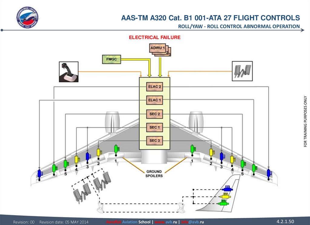
49. ROLL CONTROL ABNORMAL OPERATION ELECTRICAL FAILURE In case of total electrical loss, induced roll is obtained by using the
AAS-TM A320 Cat. B1 001-ATA 27 FLIGHT CONTROLSROLL/YAW - ROLL CONTROL ABNORMAL OPERATION
ROLL CONTROL ABNORMAL OPERATION
FOR TRAINING PURPOSES ONLY
ELECTRICAL FAILURE
In case of total electrical loss, induced roll is obtained by using the rudder pedals, which have a mechanical control.
Revision: 00
Revision date: 05 MAY 2014
Aeroflot Aviation School | www.avb.ru | info@avb.ru
4.2.1.49
50.
AAS-TM A320 Cat. B1 001-ATA 27 FLIGHT CONTROLSROLL/YAW - ROLL CONTROL ABNORMAL OPERATION
FOR TRAINING PURPOSES ONLY
ELECTRICAL FAILURE
Revision: 00
Revision date: 05 MAY 2014
Aeroflot Aviation School | www.avb.ru | info@avb.ru
4.2.1.50
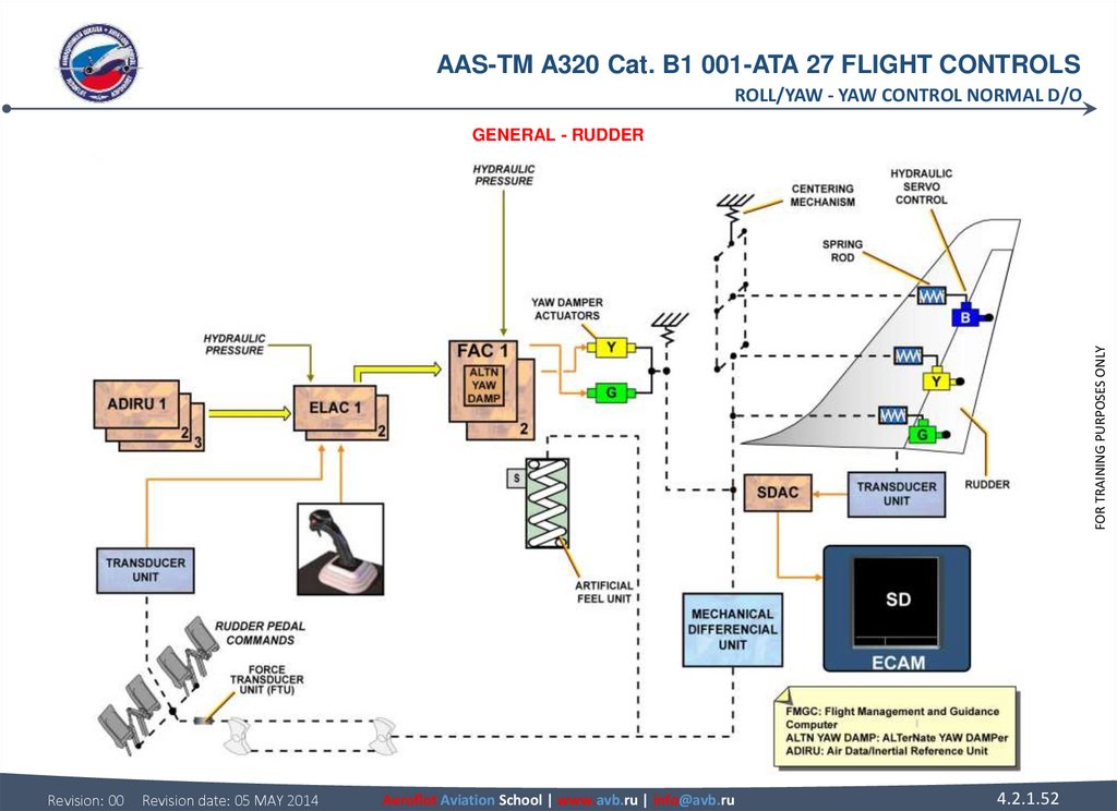
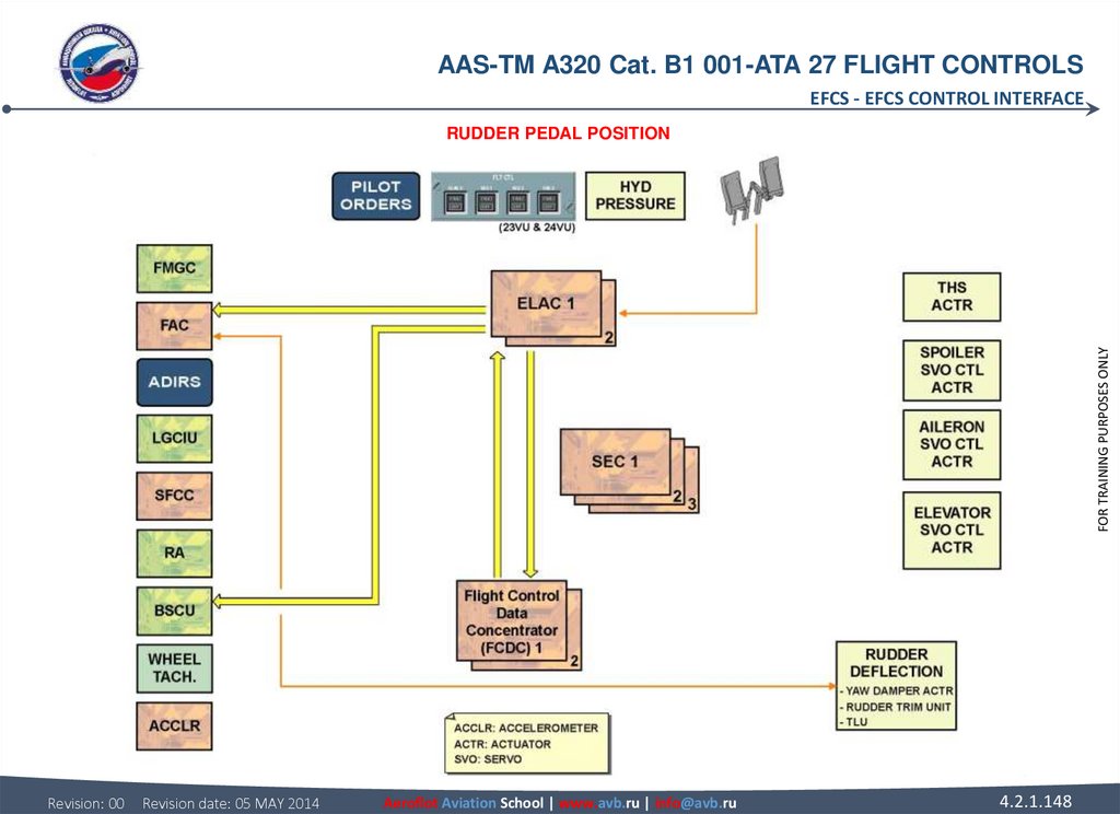
51. YAW CONTROL NORMAL D/O GENERAL The yaw control is done by the rudder, with a maximum deflection of 25° for the A320 and A321,
AAS-TM A320 Cat. B1 001-ATA 27 FLIGHT CONTROLSROLL/YAW - YAW CONTROL NORMAL D/O
YAW CONTROL NORMAL D/O
GENERAL
The yaw control is done by the rudder, with a maximum deflection of 25° for the A320 and A321, and 30° for the A318 and A319. The
rudder is operated by three moving body servocontrols with a common mechanical input.
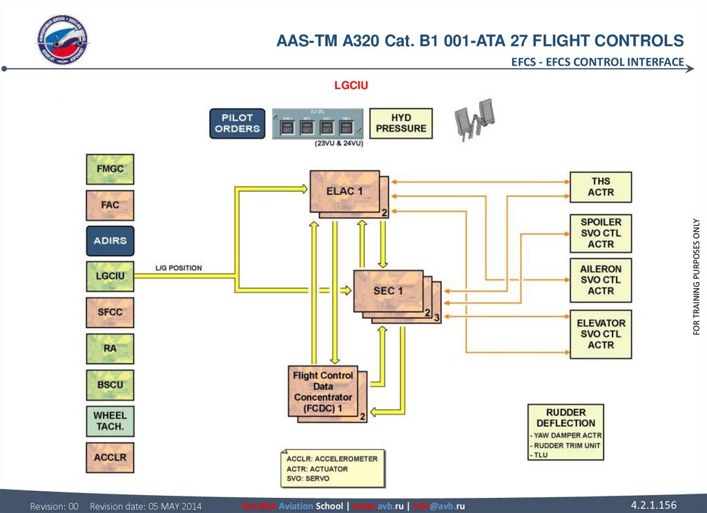
Mechanical rudder control is always available from the rudder pedals. The pedal position signals are sent to the ELevator Aileron
Computers (ELACs) by the transducer (XDCR) unit. If installed, the Force Transducer Unit (FTU) is used to measure pilots forces
applied on the pedals. This information is not used in flight control system but transmitted to the Flight Control Data Concentrator
(FCDC) to be recorded by the Digital Flight Data Recorder (DFDR).
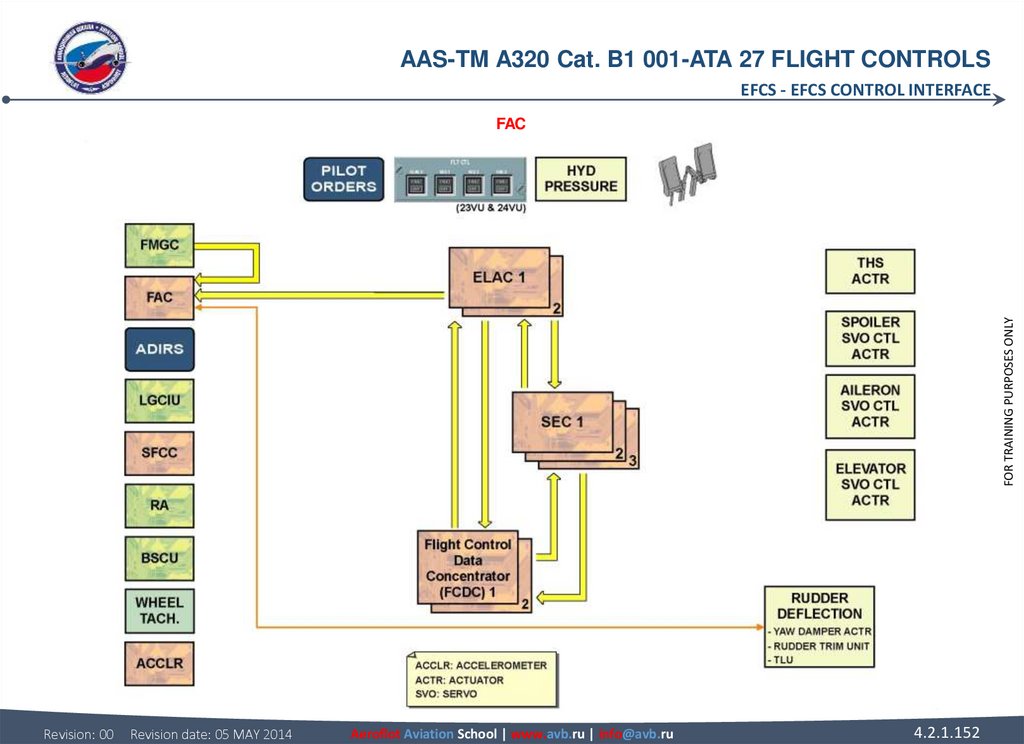
ELAC
In flight, the ELACs transmit the yaw damping and turn coordination to the Flight Augmentation Computers (FACs) for rudder
deflection. There is no feedback to the pedals for yaw damping and turn coordination.
FAC
The two FACs control the yaw damper servo controls. FAC 1 has priority. FAC 2 is in hot stand-by.
RUDDER
The rudder is powered by three hydraulic actuators operating in parallel. The position of the rudder is transmitted to the System Data
Acquisition Concentrator (SDAC) through a position XDCR unit. This position is shown on the lower display unit of the ECAM.
Revision: 00
Revision date: 05 MAY 2014
Aeroflot Aviation School | www.avb.ru | info@avb.ru
4.2.1.51
FOR TRAINING PURPOSES ONLY
RUDDER PEDALS
The two pairs of rudder pedals are connected together. They are linked by a cable loop to the mechanical summing point which in
turn is connected to the hydraulic rudder actuators via a differential unit.
52.
AAS-TM A320 Cat. B1 001-ATA 27 FLIGHT CONTROLSROLL/YAW - YAW CONTROL NORMAL D/O
FOR TRAINING PURPOSES ONLY
GENERAL - RUDDER
Revision: 00
Revision date: 05 MAY 2014
Aeroflot Aviation School | www.avb.ru | info@avb.ru
4.2.1.52
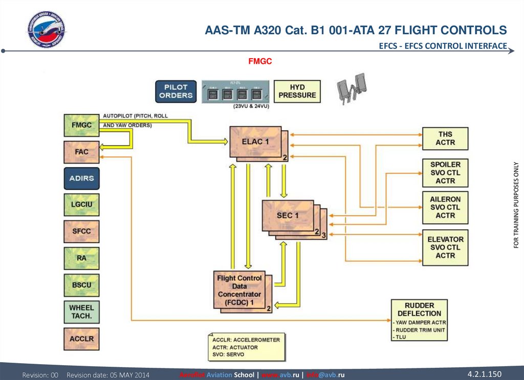
53. YAW CONTROL NORMAL D/O FMGC When the autopilot is engaged, the Flight Management and Guidance Computers (FMGCs) send commands
AAS-TM A320 Cat. B1 001-ATA 27 FLIGHT CONTROLSROLL/YAW - YAW CONTROL NORMAL D/O
YAW CONTROL NORMAL D/O
FMGC
When the autopilot is engaged, the Flight Management and Guidance Computers (FMGCs) send commands to the FACs for rudder
trimming, yaw control and yaw damping function. The FMGCs energize the artificial feel stiffening solenoid to increase the threshold
of the rudder artificial feel and to avoid unintentional autopilot disconnection.
FOR TRAINING PURPOSES ONLY
YAW DAMPING
The yaw dampers servo activation controls are connected to the rudder hydraulic actuators through a mechanical differential unit:
each servo actuator is controlled by its related FAC. No feedback to the rudder pedals is given thanks to the differential unit.
Revision: 00
Revision date: 05 MAY 2014
Aeroflot Aviation School | www.avb.ru | info@avb.ru
4.2.1.53
54.
AAS-TM A320 Cat. B1 001-ATA 27 FLIGHT CONTROLSROLL/YAW - YAW CONTROL NORMAL D/O
FOR TRAINING PURPOSES ONLY
FMGC & YAW DAMPING
Revision: 00
Revision date: 05 MAY 2014
Aeroflot Aviation School | www.avb.ru | info@avb.ru
4.2.1.54
55. YAW CONTROL NORMAL D/O RUDDER TRIM The rudder trim is achieved by one or two electric motors at a time, each controlled by its
AAS-TM A320 Cat. B1 001-ATA 27 FLIGHT CONTROLSROLL/YAW - YAW CONTROL NORMAL D/O
YAW CONTROL NORMAL D/O
RUDDER LIMITATION
Rudder deflection limitation is achieved by a variable stop unit driven by one or two electric motors at a time. Each motor is controlled
by its associated FAC. The rudder deflection becomes limited as speed is increased.
Revision: 00
Revision date: 05 MAY 2014
Aeroflot Aviation School | www.avb.ru | info@avb.ru
4.2.1.55
FOR TRAINING PURPOSES ONLY
RUDDER TRIM
The rudder trim is achieved by one or two electric motors at a time, each controlled by its associated FAC. In manual flight, the pilot
can apply rudder trim at 1°/sec from the RUDder TRIM rotary switch.
Also, an asymmetry compensation function is available in case of lateral asymmetry, and a yaw automatic trim is active for lateral
asymmetry and engine failure compensation at 5°/sec.
Trimming causes rudder pedal movement.
56.
AAS-TM A320 Cat. B1 001-ATA 27 FLIGHT CONTROLSROLL/YAW - YAW CONTROL NORMAL D/O
FOR TRAINING PURPOSES ONLY
RUDDER TRIM & RUDDER LIMITATION
Revision: 00
Revision date: 05 MAY 2014
Aeroflot Aviation School | www.avb.ru | info@avb.ru
4.2.1.56
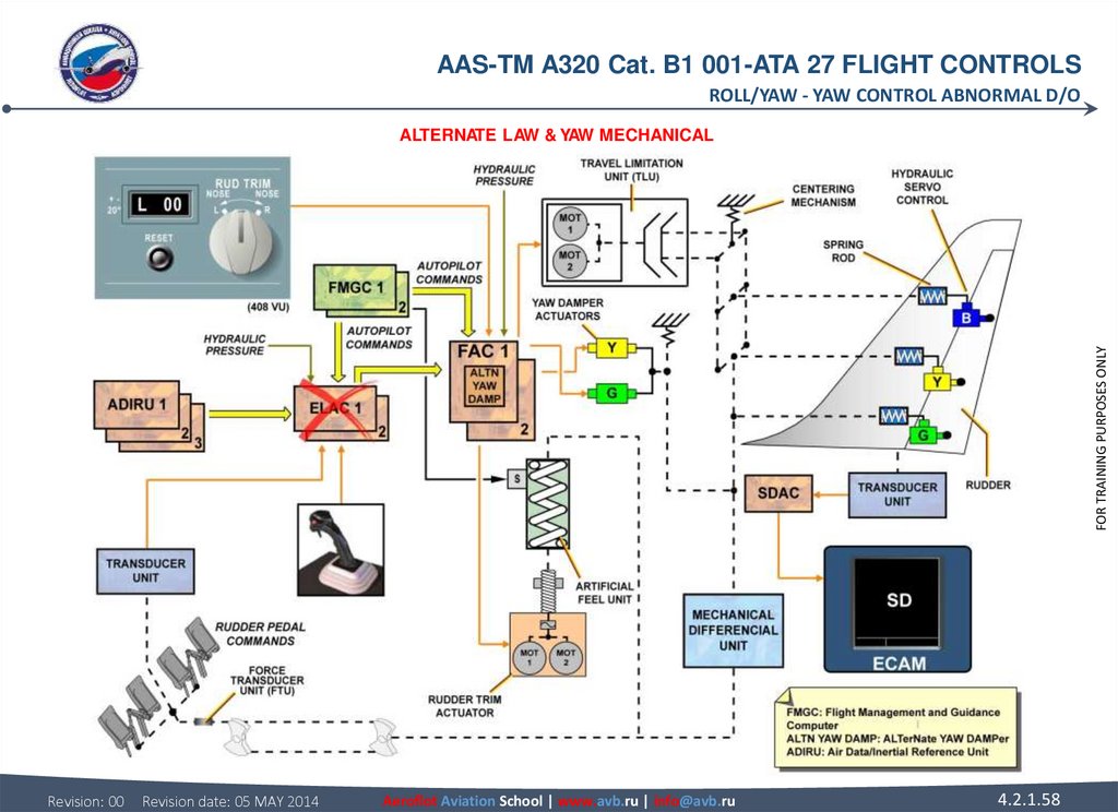
57. YAW CONTROL ABNORMAL D/O ALTERNATE LAW The alternate yaw damper law computed in the Flight Augmentation Computer (FAC) becomes
AAS-TM A320 Cat. B1 001-ATA 27 FLIGHT CONTROLSROLL/YAW - YAW CONTROL ABNORMAL D/O
YAW CONTROL ABNORMAL D/O
The alternate yaw damper law also becomes active in these cases:
• two Air Data References (ADRs) or two Inertial References (IRs) or two ELevator Aileron Computers (ELACs) or both ailerons or all
spoilers fail or blue+green hydraulic low pressure or of pitch normal law is lost,
• the alternate law in FAC 1 is active with the emergency electrical supply (emergency generator running),
• the yaw damper authority is limited to +/- 5° rudder deflection.
YAW MECHANICAL
The mechanical rudder control, which is available at all times, must be used following the failures shown below:
• two FACs or three ADRs or three IRs or green+yellow hydraulic low pressure or electrical power on batteries only.
NOTE: In case of a dual FAC failure, a specific channel in each FAC selects the rudder.
Revision: 00
Revision date: 05 MAY 2014
Aeroflot Aviation School | www.avb.ru | info@avb.ru
4.2.1.57
FOR TRAINING PURPOSES ONLY
ALTERNATE LAW
The alternate yaw damper law computed in the Flight Augmentation Computer (FAC) becomes active if the roll normal law fails. Turn
coordination is no longer available.
58.
AAS-TM A320 Cat. B1 001-ATA 27 FLIGHT CONTROLSROLL/YAW - YAW CONTROL ABNORMAL D/O
FOR TRAINING PURPOSES ONLY
ALTERNATE LAW & YAW MECHANICAL
Revision: 00
Revision date: 05 MAY 2014
Aeroflot Aviation School | www.avb.ru | info@avb.ru
4.2.1.58
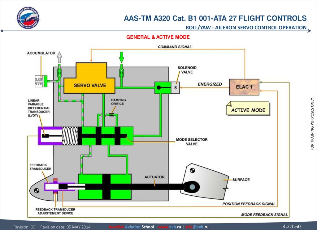
59. AILERON SERVO CONTROL OPERATION GENERAL Each aileron is equipped with two identical electro-hydraulic servo-controls. These
AAS-TM A320 Cat. B1 001-ATA 27 FLIGHT CONTROLSROLL/YAW - AILERON SERVO CONTROL OPERATION
AILERON SERVO CONTROL OPERATION
ACTIVE MODE
In the active mode, the solenoid valve is energized by the Electrical Flight Control System (EFCS). This enables the HP fluid to flow
and to put the mode selector valve in the active position. The two chambers of the actuator are thus connected to the servo-valve
control lines. Theservo-control is then in the active mode. The Linear Variable-Differential Transducer (LVDT) supplies an electrical
signal to the ELAC, which identifies this change of state. The feedback transducer (also called LVDT) gives the servo-loop feedback.
Revision: 00
Revision date: 05 MAY 2014
Aeroflot Aviation School | www.avb.ru | info@avb.ru
4.2.1.59
FOR TRAINING PURPOSES ONLY
GENERAL
Each aileron is equipped with two identical electro-hydraulic servo-controls.
These servo-controls have two modes:
• the active mode
• the damping mode.
60.
AAS-TM A320 Cat. B1 001-ATA 27 FLIGHT CONTROLSROLL/YAW - AILERON SERVO CONTROL OPERATION
FOR TRAINING PURPOSES ONLY
GENERAL & ACTIVE MODE
Revision: 00
Revision date: 05 MAY 2014
Aeroflot Aviation School | www.avb.ru | info@avb.ru
4.2.1.60
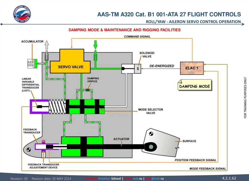
61. AILERON SERVO CONTROL OPERATION DAMPING MODE In damping mode, the actuator follows the control surface movements. In this
AAS-TM A320 Cat. B1 001-ATA 27 FLIGHT CONTROLSROLL/YAW - AILERON SERVO CONTROL OPERATION
AILERON SERVO CONTROL OPERATION
MAINTENANCE AND RIGGING FACILITIES
After replacement of the servo-control, it is necessary to adjust the feedback transducer (LVDT). It is necessary to get an equal
voltage in the secondary winding (electrical zero) when the aileron is in neutral position. This is done through an action on the
feedback transducer adjustment device located on the actuator.
Revision: 00
Revision date: 05 MAY 2014
Aeroflot Aviation School | www.avb.ru | info@avb.ru
4.2.1.61
FOR TRAINING PURPOSES ONLY
DAMPING MODE
In damping mode, the actuator follows the control surface movements. In this configuration, the solenoid valve is de-energized and
the mode selector valve moves under the action of its spring. The two chambers of the actuator are thus interconnected through the
damping orifice. The LVDT identifies this change of state and transmit it to the EFCS.
The fluid reserve allows to hold the volume of fluid in the actuator chambers:
• if the temperature of the hydraulic fluid changes or,
• if there is a leakage.
The fluid reserve is permanently connected to the return line of the servo-valve.
62.
AAS-TM A320 Cat. B1 001-ATA 27 FLIGHT CONTROLSROLL/YAW - AILERON SERVO CONTROL OPERATION
FOR TRAINING PURPOSES ONLY
DAMPING MODE & MAINTENANCE AND RIGGING FACILITIES
Revision: 00
Revision date: 05 MAY 2014
Aeroflot Aviation School | www.avb.ru | info@avb.ru
4.2.1.62
63. SPOILER SERVO CONTROL OPERATION ACTIVE MODE In active mode the spoiler servo control actuator is hydraulically supplied.
AAS-TM A320 Cat. B1 001-ATA 27 FLIGHT CONTROLSROLL/YAW - SPOILER SERVO CONTROL OPERATION
SPOILER SERVO CONTROL OPERATION
FOR TRAINING PURPOSES ONLY
ACTIVE MODE
In active mode the spoiler servo control actuator is hydraulically supplied. According to the command signal to the servo valve the
spoiler surface will extend or retract. The feedback transducer Linear Variable Differential Transducer (LVDT) provide(s) the servo
loop feedback.
Revision: 00
Revision date: 05 MAY 2014
Aeroflot Aviation School | www.avb.ru | info@avb.ru
4.2.1.63
64.
AAS-TM A320 Cat. B1 001-ATA 27 FLIGHT CONTROLSROLL/YAW - SPOILER SERVO CONTROL OPERATION
FOR TRAINING PURPOSES ONLY
ACTIVE MODE
Revision: 00
Revision date: 05 MAY 2014
Aeroflot Aviation School | www.avb.ru | info@avb.ru
4.2.1.64
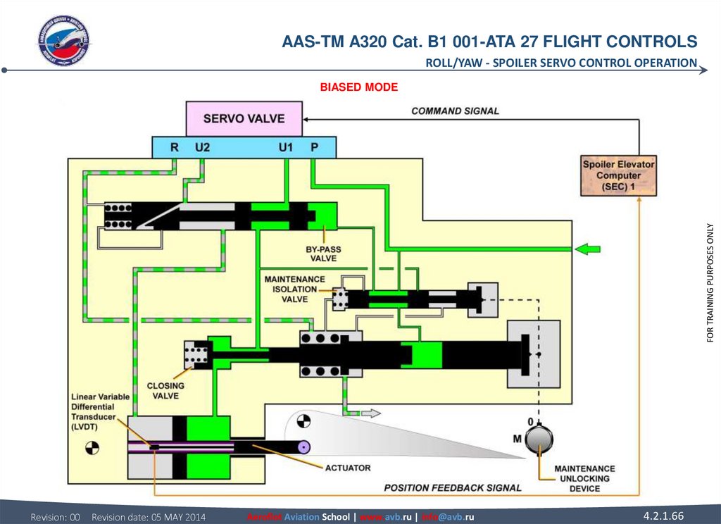
65. SPOILER SERVO CONTROL OPERATION BIASED MODE The servo-control actuator is pressurized. Due to an electrical failure the command
AAS-TM A320 Cat. B1 001-ATA 27 FLIGHT CONTROLSROLL/YAW - SPOILER SERVO CONTROL OPERATION
SPOILER SERVO CONTROL OPERATION
FOR TRAINING PURPOSES ONLY
BIASED MODE
The servo-control actuator is pressurized. Due to an electrical failure the command signal is lost. The biased servo valve pressurizes
the retraction chamber. The spoiler actuator stays pressurized and the spoiler remains retracted.
Revision: 00
Revision date: 05 MAY 2014
Aeroflot Aviation School | www.avb.ru | info@avb.ru
4.2.1.65
66.
AAS-TM A320 Cat. B1 001-ATA 27 FLIGHT CONTROLSROLL/YAW - SPOILER SERVO CONTROL OPERATION
FOR TRAINING PURPOSES ONLY
BIASED MODE
Revision: 00
Revision date: 05 MAY 2014
Aeroflot Aviation School | www.avb.ru | info@avb.ru
4.2.1.66
67. SPOILER SERVO CONTROL OPERATION LOCKED MODE In locked mode, the hydraulic pressure is lost. The closing valve closes the
AAS-TM A320 Cat. B1 001-ATA 27 FLIGHT CONTROLSROLL/YAW - SPOILER SERVO CONTROL OPERATION
SPOILER SERVO CONTROL OPERATION
FOR TRAINING PURPOSES ONLY
LOCKED MODE
In locked mode, the hydraulic pressure is lost. The closing valve closes the retraction chamber. The surface can only be moved
towards the retracted position, pushed by aerodynamical forces.
Revision: 00
Revision date: 05 MAY 2014
Aeroflot Aviation School | www.avb.ru | info@avb.ru
4.2.1.67
68.
AAS-TM A320 Cat. B1 001-ATA 27 FLIGHT CONTROLSROLL/YAW - SPOILER SERVO CONTROL OPERATION
FOR TRAINING PURPOSES ONLY
LOCKED MODE
Revision: 00
Revision date: 05 MAY 2014
Aeroflot Aviation School | www.avb.ru | info@avb.ru
4.2.1.68
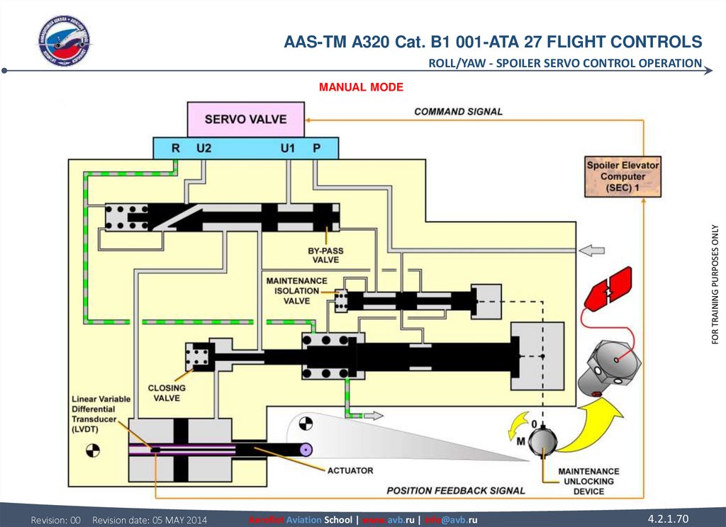
69. SPOILER SERVO CONTROL OPERATION MANUAL MODE To be unlocked, the servo control actuator must be depressurized. The maintenance
AAS-TM A320 Cat. B1 001-ATA 27 FLIGHT CONTROLSROLL/YAW - SPOILER SERVO CONTROL OPERATION
SPOILER SERVO CONTROL OPERATION
FOR TRAINING PURPOSES ONLY
MANUAL MODE
To be unlocked, the servo control actuator must be depressurized. The maintenance unlocking device can be engaged thanks to a
key equipped with a red flame. This tool cannot be removed when the servo control is in maintenance mode. Once the maintenance
unlocking device is engaged the spoiler surface can be raised manually for inspection purposes.
Revision: 00
Revision date: 05 MAY 2014
Aeroflot Aviation School | www.avb.ru | info@avb.ru
4.2.1.69
70.
AAS-TM A320 Cat. B1 001-ATA 27 FLIGHT CONTROLSROLL/YAW - SPOILER SERVO CONTROL OPERATION
FOR TRAINING PURPOSES ONLY
MANUAL MODE
Revision: 00
Revision date: 05 MAY 2014
Aeroflot Aviation School | www.avb.ru | info@avb.ru
4.2.1.70
71. RUDDER TRIM ACTUATOR GENERAL The rudder trim actuator is installed on the rudder system, in the tail area and it's or are one
AAS-TM A320 Cat. B1 001-ATA 27 FLIGHT CONTROLSROLL/YAW - RUDDER TRIM ACTUATOR
RUDDER TRIM ACTUATOR
CONTROLS
The rudder trim actuator is an electromechanical unit, which converts the electrical input from the Flight Augmentation Computers
(FACs) into a rotation of its output shaft. The rudder trim actuator can be controlled either by the RUDder TRIM control switch located
in the center pedestal of the cockpit, in manual mode, or by the Flight Management & Guidance Computers (FMGCs) in AP mode. In
both cases orders are sent via the FACs. In automatic control, the rudder trim function controlled by the FAC, fulfills the generation
and the accomplishment of the engine failure recovery function. In this case, the engine failure compensation slow law orders are
sent to the rudder trim actuator. The AP also provides signals, which validate the detection of engine failure as a function of the
engine rating.
DESCRIPTION/OPERATION
The rudder trim actuator has two DC motors, installed on the same shaft. Each one is controlled by one independent electronic
module, with only one motor operating at a time, via FAC1 or 2. The motors permanently coupled to a reduction gear, drive the output
shaft, via a torque limiter. Then the output shaft drives four Rotary Variable Differential Transducers (RVDTs), transmitting the output
shaft position signal to the FACs.
Revision: 00
Revision date: 05 MAY 2014
Aeroflot Aviation School | www.avb.ru | info@avb.ru
4.2.1.71
FOR TRAINING PURPOSES ONLY
GENERAL
The rudder trim actuator is installed on the rudder system, in the tail area and it's or are one of the mechanical inputs of the rudder
servo controls. The rudder trim actuator enables the zero force position of the artificial feel and trim unit to be adjusted.
72.
AAS-TM A320 Cat. B1 001-ATA 27 FLIGHT CONTROLSROLL/YAW - RUDDER TRIM ACTUATOR
FOR TRAINING PURPOSES ONLY
GENERAL - DESCRIPTION/OPERATION
Revision: 00
Revision date: 05 MAY 2014
Aeroflot Aviation School | www.avb.ru | info@avb.ru
4.2.1.72
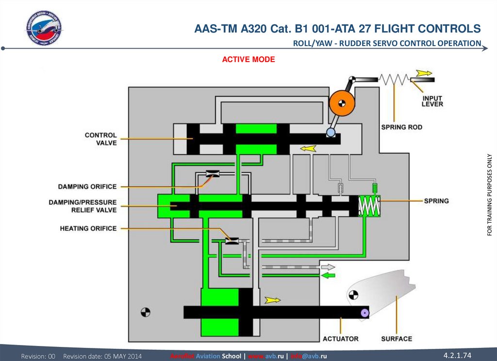
73. RUDDER SERVO CONTROL OPERATION ACTIVE MODE When the rudder servo control actuator is in active mode, the actuator moves to the
AAS-TM A320 Cat. B1 001-ATA 27 FLIGHT CONTROLSROLL/YAW - RUDDER SERVO CONTROL OPERATION
RUDDER SERVO CONTROL OPERATION
FOR TRAINING PURPOSES ONLY
ACTIVE MODE
When the rudder servo control actuator is in active mode, the actuator moves to the right or to the left according to the control valve
position. The high pressure is connected to the return via the heating orifice; this fulfills the permanent heating leakage.
Revision: 00
Revision date: 05 MAY 2014
Aeroflot Aviation School | www.avb.ru | info@avb.ru
4.2.1.73
74.
AAS-TM A320 Cat. B1 001-ATA 27 FLIGHT CONTROLSROLL/YAW - RUDDER SERVO CONTROL OPERATION
FOR TRAINING PURPOSES ONLY
ACTIVE MODE
Revision: 00
Revision date: 05 MAY 2014
Aeroflot Aviation School | www.avb.ru | info@avb.ru
4.2.1.74
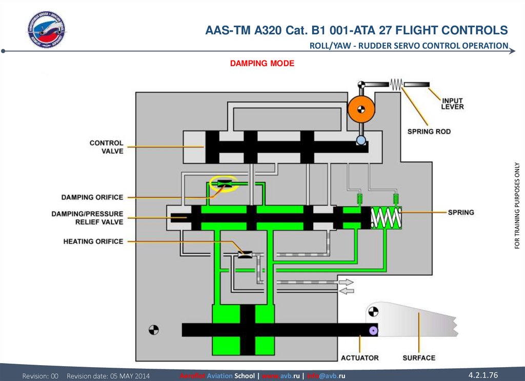
75. RUDDER SERVO CONTROL OPERATION DAMPING MODE The rudder servo control actuator changes to damping mode, as soon as the hydraulic
AAS-TM A320 Cat. B1 001-ATA 27 FLIGHT CONTROLSROLL/YAW - RUDDER SERVO CONTROL OPERATION
RUDDER SERVO CONTROL OPERATION
FOR TRAINING PURPOSES ONLY
DAMPING MODE
The rudder servo control actuator changes to damping mode, as soon as the hydraulic pressure supply is cut. When the servo control
is depressurized, the spring sets the damping and pressure-relief valve to the bypass position, and the hydraulic fluid goes from one
chamber to the other via the damping orifice.
Revision: 00
Revision date: 05 MAY 2014
Aeroflot Aviation School | www.avb.ru | info@avb.ru
4.2.1.75
76.
AAS-TM A320 Cat. B1 001-ATA 27 FLIGHT CONTROLSROLL/YAW - RUDDER SERVO CONTROL OPERATION
FOR TRAINING PURPOSES ONLY
DAMPING MODE
Revision: 00
Revision date: 05 MAY 2014
Aeroflot Aviation School | www.avb.ru | info@avb.ru
4.2.1.76
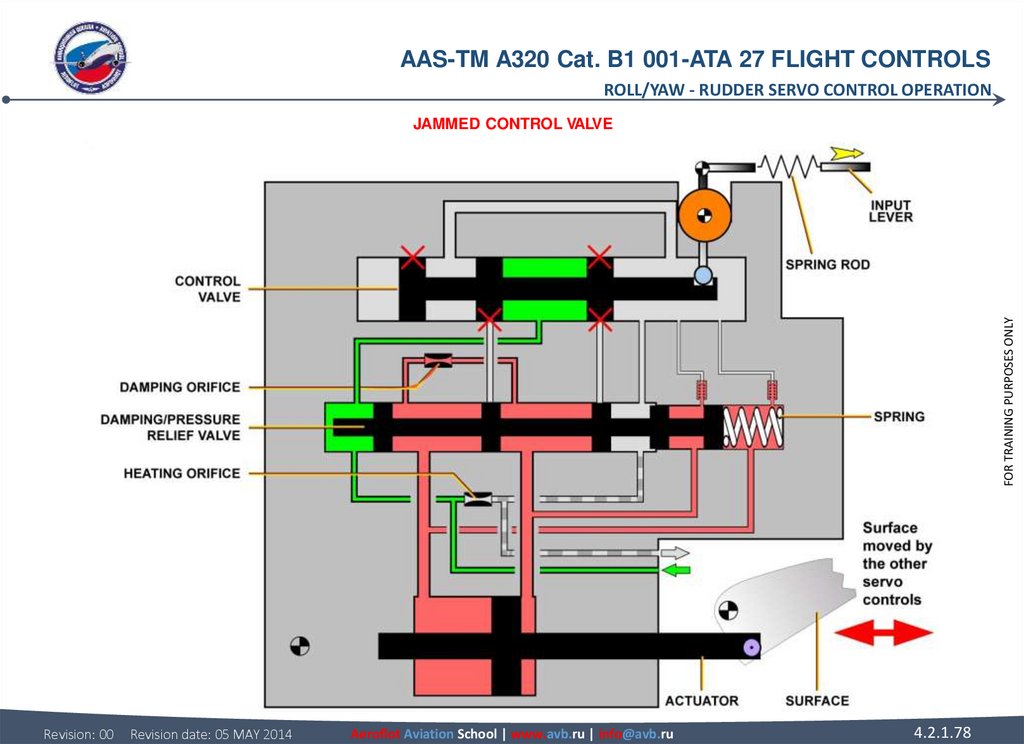
77. RUDDER SERVO CONTROL OPERATION JAMMED CONTROL VALVE If the control valve jams, the rudder servo control actuator follows the
AAS-TM A320 Cat. B1 001-ATA 27 FLIGHT CONTROLSROLL/YAW - RUDDER SERVO CONTROL OPERATION
RUDDER SERVO CONTROL OPERATION
FOR TRAINING PURPOSES ONLY
JAMMED CONTROL VALVE
If the control valve jams, the rudder servo control actuator follows the rudder surface movement, ensured by the other rudder servo
controls. Rudder locking or runaway in the event of a servo control valve jamming is prevented by a spring rod and pressure relief
valve arrangement.
Revision: 00
Revision date: 05 MAY 2014
Aeroflot Aviation School | www.avb.ru | info@avb.ru
4.2.1.77
78.
AAS-TM A320 Cat. B1 001-ATA 27 FLIGHT CONTROLSROLL/YAW - RUDDER SERVO CONTROL OPERATION
FOR TRAINING PURPOSES ONLY
JAMMED CONTROL VALVE
Revision: 00
Revision date: 05 MAY 2014
Aeroflot Aviation School | www.avb.ru | info@avb.ru
4.2.1.78
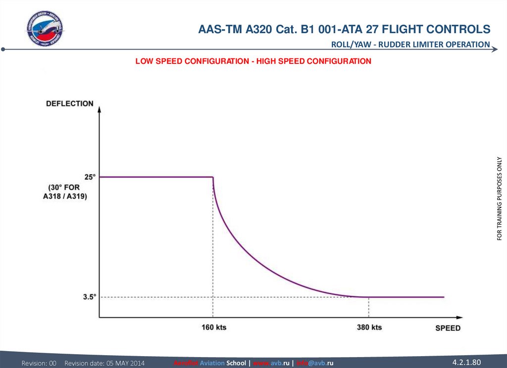
79. RUDDER LIMITER OPERATION LOW SPEED CONFIGURATION Under 160 kts the stops are in low-speed configuration. Full input/output
AAS-TM A320 Cat. B1 001-ATA 27 FLIGHT CONTROLSROLL/YAW - RUDDER LIMITER OPERATION
RUDDER LIMITER OPERATION
LOW SPEED CONFIGURATION
Under 160 kts the stops are in low-speed configuration. Full input/output lever movement to the rudder servo control is available.
HIGH SPEED CONFIGURATION
Above 380 kts the stops are in high-speed configuration. Only limited input/output lever movement to the rudder servo control is
available.
Revision: 00
Revision date: 05 MAY 2014
Aeroflot Aviation School | www.avb.ru | info@avb.ru
4.2.1.79
FOR TRAINING PURPOSES ONLY
VARIABLE LIMITATION
Between 160 and 380 kts the rudder deflection is limited as a function of speed. The corresponding law is computed by the Flight
Augmentation Computers (FACs).
80.
AAS-TM A320 Cat. B1 001-ATA 27 FLIGHT CONTROLSROLL/YAW - RUDDER LIMITER OPERATION
FOR TRAINING PURPOSES ONLY
LOW SPEED CONFIGURATION - HIGH SPEED CONFIGURATION
Revision: 00
Revision date: 05 MAY 2014
Aeroflot Aviation School | www.avb.ru | info@avb.ru
4.2.1.80
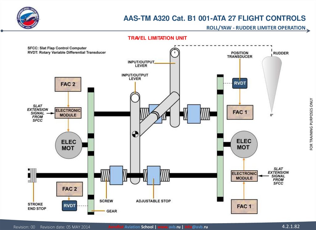
81. RUDDER LIMITER OPERATION TRAVEL LIMITATION UNIT The mechanical design of the Travel Limitation Unit (TLU) is such that a single
AAS-TM A320 Cat. B1 001-ATA 27 FLIGHT CONTROLSROLL/YAW - RUDDER LIMITER OPERATION
RUDDER LIMITER OPERATION
FOR TRAINING PURPOSES ONLY
TRAVEL LIMITATION UNIT
The mechanical design of the Travel Limitation Unit (TLU) is such that a single mechanical failure (rupture or disconnection) cannot
cause the loss of the travel limitation function. The TLU has two brushless electric motors separately controlled by an electronic
assembly. Each motor drives two screws via a reduction gear and permits the symmetrical linear displacement of two nuts used as
adjustable stops. A non-locking rotary stop limits the stroke of one of the screw/nut assemblies which are irreversible. There are two
levers on each connection shaft; one is connected to the input rod and the other is used as a punctual stop. The movement of each
screw is transmitted to a Rotary Variable Differential Transducer via the reduction gear which permits to indicate the position of the
variable stop.
NOTE: To prevent icing, there is a heating system which includes two coils and their regulating thermostats.
Revision: 00
Revision date: 05 MAY 2014
Aeroflot Aviation School | www.avb.ru | info@avb.ru
4.2.1.81
82.
AAS-TM A320 Cat. B1 001-ATA 27 FLIGHT CONTROLSROLL/YAW - RUDDER LIMITER OPERATION
FOR TRAINING PURPOSES ONLY
TRAVEL LIMITATION UNIT
Revision: 00
Revision date: 05 MAY 2014
Aeroflot Aviation School | www.avb.ru | info@avb.ru
4.2.1.82
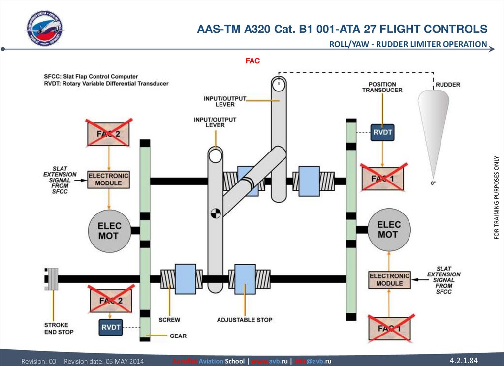
83. RUDDER LIMITER OPERATION FAC If both FACs fail, the rudder travel limitation value is frozen immediately. In this case, an
AAS-TM A320 Cat. B1 001-ATA 27 FLIGHT CONTROLSROLL/YAW - RUDDER LIMITER OPERATION
RUDDER LIMITER OPERATION
FAC
If both FACs fail, the rudder travel limitation value is frozen immediately. In this case, an emergency control brings back the stops to
the low speed configuration (maximum possible deflection of the rudder) when slats are extended.
FOR TRAINING PURPOSES ONLY
NOTE: To bring back the stops to the low speed configuration, the motors are used as 2-phase asynchronous motor energized by
26V 400 Hz power. This control mode is achieved when the coil of a specific relay ( each motor has a relay ) is energized for a period
of 30 s approximately. This time is sufficient to bring back the stops to the low speed configuration.
Revision: 00
Revision date: 05 MAY 2014
Aeroflot Aviation School | www.avb.ru | info@avb.ru
4.2.1.83
84.
AAS-TM A320 Cat. B1 001-ATA 27 FLIGHT CONTROLSROLL/YAW - RUDDER LIMITER OPERATION
FOR TRAINING PURPOSES ONLY
FAC
Revision: 00
Revision date: 05 MAY 2014
Aeroflot Aviation School | www.avb.ru | info@avb.ru
4.2.1.84
85. YAW DAMPER SERVO ACTUATOR OPERATION ACTIVE MODE The actuator is in active mode when both solenoid valves are energized; the
AAS-TM A320 Cat. B1 001-ATA 27 FLIGHT CONTROLSROLL/YAW - YAW DAMPER SERVO ACTUATOR OPERATION
YAW DAMPER SERVO ACTUATOR OPERATION
ACTIVE MODE
The actuator is in active mode when both solenoid valves are energized; the hydraulic pressure and the servo valve are available.
The two selector valves are connected to the servovalve outputs and allow the servo actuator to operate in active mode. In this case
the pressure switch is not activated. The feedback transducer of the Linear Variable Differential Transducer (LVDT) type supplies the
servo loop feedback information to the Flight Augmentation Computers (FACs). FAC 1 controls and monitors the green servo actuator
and FAC 2 the yellow one. Only one yaw damper at a time is in active mode, the other one is in a by-pass mode.
Revision: 00
Revision date: 05 MAY 2014
Aeroflot Aviation School | www.avb.ru | info@avb.ru
FOR TRAINING PURPOSES ONLY
MONITORING
A pressure switch installed on to the servo actuator detects any different position between the selector valves.
4.2.1.85
86.
AAS-TM A320 Cat. B1 001-ATA 27 FLIGHT CONTROLSROLL/YAW - YAW DAMPER SERVO ACTUATOR OPERATION
FOR TRAINING PURPOSES ONLY
ACTIVE MODE & MONITORING
Revision: 00
Revision date: 05 MAY 2014
Aeroflot Aviation School | www.avb.ru | info@avb.ru
4.2.1.86
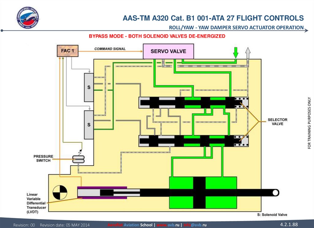
87. YAW DAMPER SERVO ACTUATOR OPERATION BYPASS MODE BOTH SOLENOID VALVES DE-ENERGIZED The two-solenoid valves are de-energized and
AAS-TM A320 Cat. B1 001-ATA 27 FLIGHT CONTROLSROLL/YAW - YAW DAMPER SERVO ACTUATOR OPERATION
YAW DAMPER SERVO ACTUATOR OPERATION
FOR TRAINING PURPOSES ONLY
BYPASS MODE
BOTH SOLENOID VALVES DE-ENERGIZED
The two-solenoid valves are de-energized and the associated selector valves are set to the bypass mode under the action of their
spring. The two-piston chambers are, in this case, interconnected. The pressure switch is not activated.
Revision: 00
Revision date: 05 MAY 2014
Aeroflot Aviation School | www.avb.ru | info@avb.ru
4.2.1.87
88.
AAS-TM A320 Cat. B1 001-ATA 27 FLIGHT CONTROLSROLL/YAW - YAW DAMPER SERVO ACTUATOR OPERATION
FOR TRAINING PURPOSES ONLY
BYPASS MODE - BOTH SOLENOID VALVES DE-ENERGIZED
Revision: 00
Revision date: 05 MAY 2014
Aeroflot Aviation School | www.avb.ru | info@avb.ru
4.2.1.88
89. YAW DAMPER SERVO ACTUATOR OPERATION BYPASS MODE (continued) ONE SOLENOID VALVE DE-ENERGIZED ONLY In case of a single electrical
AAS-TM A320 Cat. B1 001-ATA 27 FLIGHT CONTROLSROLL/YAW - YAW DAMPER SERVO ACTUATOR OPERATION
YAW DAMPER SERVO ACTUATOR OPERATION
FOR TRAINING PURPOSES ONLY
BYPASS MODE (continued)
ONE SOLENOID VALVE DE-ENERGIZED ONLY
In case of a single electrical failure causing one selector valve to be in bypass mode, the other being in active mode, the result lies in
the interconnection of the two actuator chambers, thus the actuator is in bypass mode. In this way, by means of the pressure switch,
which is now connected to the supply pressure, this abnormal configuration is indicated to the FACs.
Revision: 00
Revision date: 05 MAY 2014
Aeroflot Aviation School | www.avb.ru | info@avb.ru
4.2.1.89
90.
AAS-TM A320 Cat. B1 001-ATA 27 FLIGHT CONTROLSROLL/YAW - YAW DAMPER SERVO ACTUATOR OPERATION
FOR TRAINING PURPOSES ONLY
BYPASS MODE - ONE SOLENOID VALVE DE-ENERGIZED ONLY
Revision: 00
Revision date: 05 MAY 2014
Aeroflot Aviation School | www.avb.ru | info@avb.ru
4.2.1.90
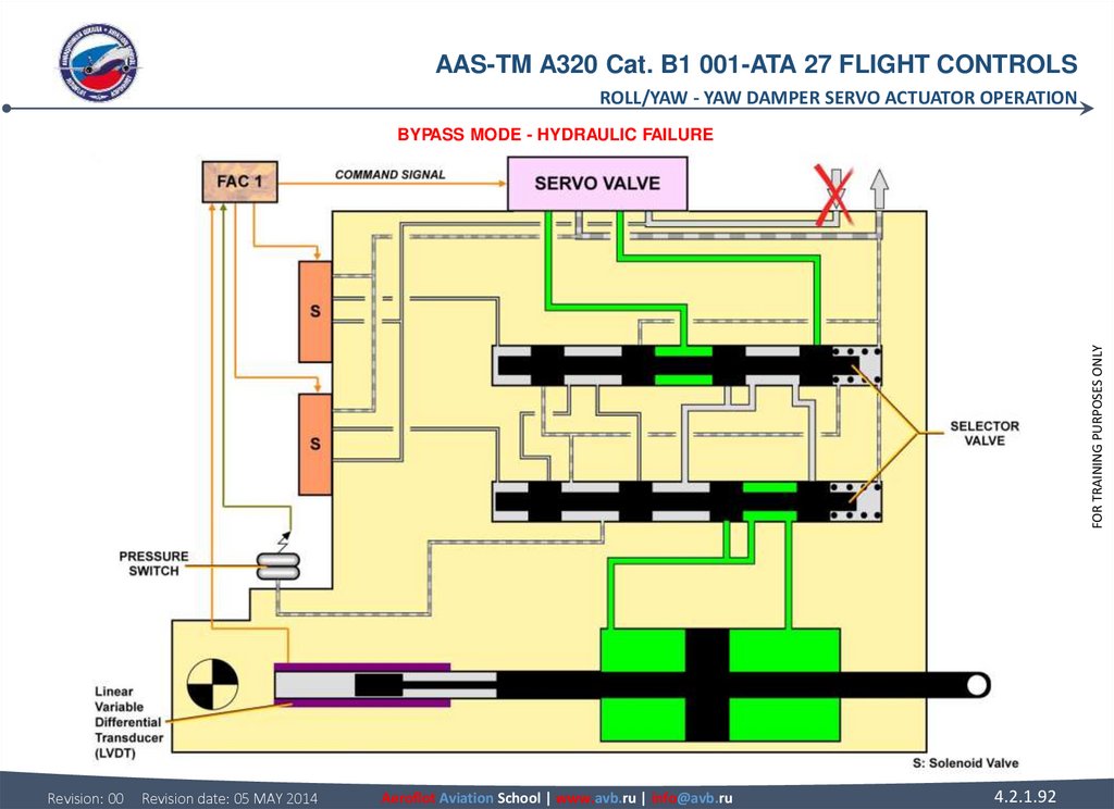
91. YAW DAMPER SERVO ACTUATOR OPERATION BYPASS MODE (continued) HYDRAULIC FAILURE With no hydraulic pressure, the two selector
AAS-TM A320 Cat. B1 001-ATA 27 FLIGHT CONTROLSROLL/YAW - YAW DAMPER SERVO ACTUATOR OPERATION
YAW DAMPER SERVO ACTUATOR OPERATION
FOR TRAINING PURPOSES ONLY
BYPASS MODE (continued)
HYDRAULIC FAILURE
With no hydraulic pressure, the two selector valves are set, under the action of their spring, in bypass mode, thus the two chambers
of the piston are interconnected. In this case, the pressure switch is not activated.
Revision: 00
Revision date: 05 MAY 2014
Aeroflot Aviation School | www.avb.ru | info@avb.ru
4.2.1.91
92.
AAS-TM A320 Cat. B1 001-ATA 27 FLIGHT CONTROLSROLL/YAW - YAW DAMPER SERVO ACTUATOR OPERATION
FOR TRAINING PURPOSES ONLY
BYPASS MODE - HYDRAULIC FAILURE
Revision: 00
Revision date: 05 MAY 2014
Aeroflot Aviation School | www.avb.ru | info@avb.ru
4.2.1.92
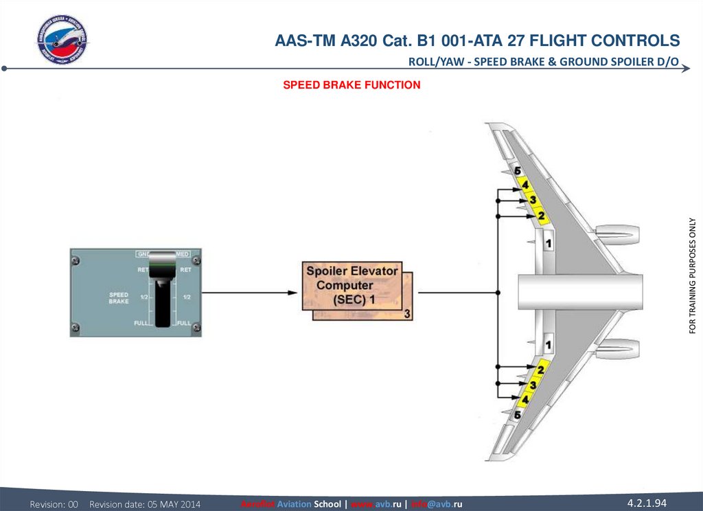
93. SPEED BRAKE & GROUND SPOILER D/O SPEED BRAKE FUNCTION The speed brake function is commanded in the flight phase following a
AAS-TM A320 Cat. B1 001-ATA 27 FLIGHT CONTROLSROLL/YAW - SPEED BRAKE & GROUND SPOILER D/O
SPEED BRAKE & GROUND SPOILER D/O
The different priorities of this function are:
• the roll order has priority over the speed brake function. When the sum of roll and speed brake commands, relative to one surface,
is greater than the maximum possible deflection, the symmetrical surface is retracted until the difference between the two surfaces
is equal to the roll order,
• if the Angle-Of-Attack (AOA) protection is activated with speed brakes extended, the speed brakes are automatically retracted.
Revision: 00
Revision date: 05 MAY 2014
Aeroflot Aviation School | www.avb.ru | info@avb.ru
4.2.1.93
FOR TRAINING PURPOSES ONLY
SPEED BRAKE FUNCTION
The speed brake function is commanded in the flight phase following a pilot's action on the speed brake lever. The speed brakes can
be driven by Spoiler and Elevator Computers (SECs) 1 and 3, and supplied from the hydraulic system. The surfaces ensuring this
function are spoilers 2 thru 4. When one surface is not available on one wing, the symmetrical one, on the other wing, is inhibited.
The switching to alternate or direct laws does not affect the speed brake function.
94.
AAS-TM A320 Cat. B1 001-ATA 27 FLIGHT CONTROLSROLL/YAW - SPEED BRAKE & GROUND SPOILER D/O
FOR TRAINING PURPOSES ONLY
SPEED BRAKE FUNCTION
Revision: 00
Revision date: 05 MAY 2014
Aeroflot Aviation School | www.avb.ru | info@avb.ru
4.2.1.94
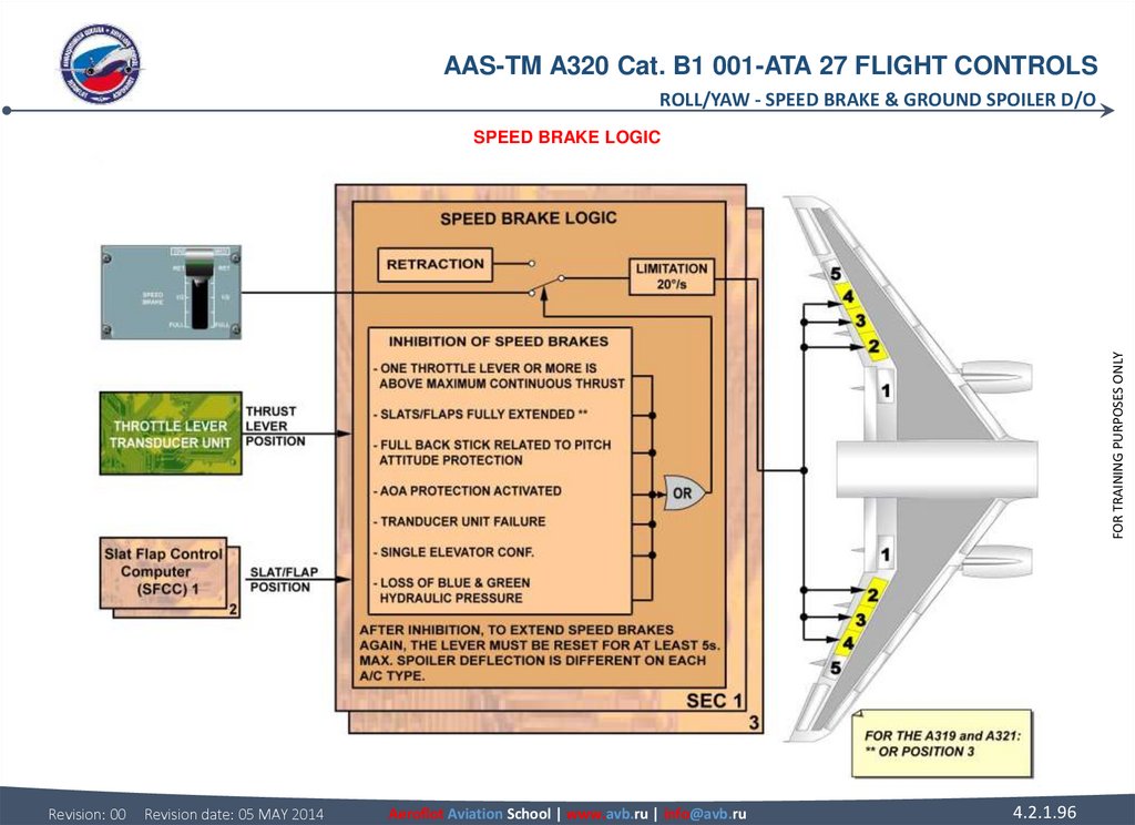
95. SPEED BRAKE & GROUND SPOILER D/O SPEED BRAKE LOGIC The speed brake control lever sends commands to the speed brakes. The SECs
AAS-TM A320 Cat. B1 001-ATA 27 FLIGHT CONTROLSROLL/YAW - SPEED BRAKE & GROUND SPOILER D/O
SPEED BRAKE & GROUND SPOILER D/O
If speed brakes are extended, they automatically retract and stay retracted until the inhibition condition stops and the lever is reset.
The SECs control a steep-approach function.
NOTE: For a steep-approach landing, on an A318, the SECs control the deflection of speed brakes No. 4, 3 and 2, to a maximum
angle of 30°, 30° and 0° respectively. For a go-around, the maximum speed brake rate is 20°/s.
Revision: 00
Revision date: 05 MAY 2014
Aeroflot Aviation School | www.avb.ru | info@avb.ru
4.2.1.95
FOR TRAINING PURPOSES ONLY
SPEED BRAKE LOGIC
The speed brake control lever sends commands to the speed brakes. The SECs receive the information from the Slats and Flaps
Control Computers (SFCCs) and the throttle lever transducer unit. Speed brake extension is inhibited in the conditions given below:
• failure of SEC 1 and 3,
• failure of left or right elevator (only spoilers 3 & 4 are inhibited),
• Angle-Of-Attack (AOA) protection is available,
• in FLAP FULL configuration (A320) or FLAP FULL or position 3 (A319/A321).
96.
AAS-TM A320 Cat. B1 001-ATA 27 FLIGHT CONTROLSROLL/YAW - SPEED BRAKE & GROUND SPOILER D/O
FOR TRAINING PURPOSES ONLY
SPEED BRAKE LOGIC
Revision: 00
Revision date: 05 MAY 2014
Aeroflot Aviation School | www.avb.ru | info@avb.ru
4.2.1.96
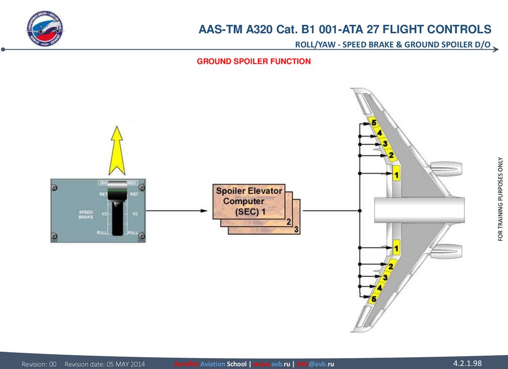
97. SPEED BRAKE & GROUND SPOILER D/O GROUND SPOILER FUNCTION When the logic conditions which determine the lift dumper extension
AAS-TM A320 Cat. B1 001-ATA 27 FLIGHT CONTROLSROLL/YAW - SPEED BRAKE & GROUND SPOILER D/O
SPEED BRAKE & GROUND SPOILER D/O
FOR TRAINING PURPOSES ONLY
GROUND SPOILER FUNCTION
When the logic conditions which determine the lift dumper extension are fulfilled, a deflection order is sent to spoilers 1 to 5, to 10º or
50º extension depending on the state of both Main Landing Gear (MLG) legs, compressed or not. Ground spoilers are armed when
the speed brake control lever is pulled up, in manual mode. Moreover, a pitch pre-command at ground spoiler extension/retraction
avoids induced pitch effects, in normal or AP mode. The ground spoiler function is automatic.
Revision: 00
Revision date: 05 MAY 2014
Aeroflot Aviation School | www.avb.ru | info@avb.ru
4.2.1.97
98.
AAS-TM A320 Cat. B1 001-ATA 27 FLIGHT CONTROLSROLL/YAW - SPEED BRAKE & GROUND SPOILER D/O
FOR TRAINING PURPOSES ONLY
GROUND SPOILER FUNCTION
Revision: 00
Revision date: 05 MAY 2014
Aeroflot Aviation School | www.avb.ru | info@avb.ru
4.2.1.98
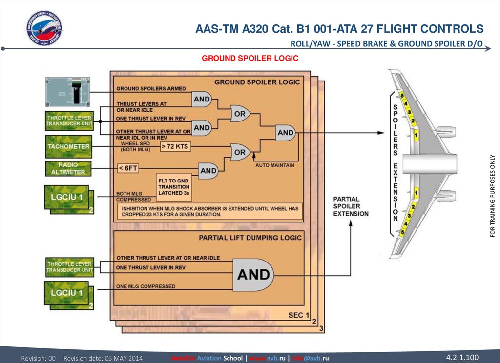
99. SPEED BRAKE & GROUND SPOILER D/O GROUND SPOILER LOGIC The ground spoiler control is entirely automatic. Achieved by the
AAS-TM A320 Cat. B1 001-ATA 27 FLIGHT CONTROLSROLL/YAW - SPEED BRAKE & GROUND SPOILER D/O
SPEED BRAKE & GROUND SPOILER D/O
Ground spoilers automatically extend when armed:
• both thrust levers at forward idle and both MLG touch down (Flight / Ground transition),
• or during Take Off (TO) run at speed greater than 72 knots (kts) and both thrust levers retarded at forward idle.
Ground spoilers automatically extended (not armed):
• when both MLG touch down and reverse is selected on at least one engine (remaining engine at idle),
• or during TO run speed greater than 72 kts and reverse is selected on at least one engine (remaining engine at idle).
Ground spoilers partially extend:
• when reverse is selected on at least one engine (remaining engine at idle) and one MLG is compressed.
This partial extension (10°), by decreasing the lift, will ease the compression of the second MLG, and consequently will lead to the
normal ground spoiler extension.
NOTE: The speed brake handle will not move during spoiler deflection or retraction. The spoiler position will be displayed on the
lower ECAM display WHEEL page.
Revision: 00
Revision date: 05 MAY 2014
Aeroflot Aviation School | www.avb.ru | info@avb.ru
4.2.1.99
FOR TRAINING PURPOSES ONLY
GROUND SPOILER LOGIC
The ground spoiler control is entirely automatic. Achieved by the spoilers 1 to 5. The maximum deflection is 50° with a deflection rate
of 30°/second.
The ground spoilers are armed:
• when the speed brake control lever is pulled up into the ARMED position.
100.
AAS-TM A320 Cat. B1 001-ATA 27 FLIGHT CONTROLSROLL/YAW - SPEED BRAKE & GROUND SPOILER D/O
FOR TRAINING PURPOSES ONLY
GROUND SPOILER LOGIC
Revision: 00
Revision date: 05 MAY 2014
Aeroflot Aviation School | www.avb.ru | info@avb.ru
4.2.1.100
101. PITCH PITCH CONTROL NORMAL D/O SIDE STICK The side stick sends electrical orders to the ELevator Aileron Computers (ELACs) and
AAS-TM A320 Cat. B1 001-ATA 27 FLIGHT CONTROLSPITCH - PITCH CONTROL NORMAL D/O
PITCH
PITCH CONTROL NORMAL D/O
ELAC
There are two ELACs. ELAC 2 normally controls the elevators and Trimmable Horizontal Stabilizer (THS) with ELAC 1 as a backup.
In case of ELAC 2 failure, ELAC 1 automatically takes over.
SEC
In case of dual ELACs failure, SEC 1 or 2 automatically takes over pitch control.
FMGC
When the Autopilot (AP) is engaged, the Flight Management and Guidance Computer (FMGC) sends AP commands to the ELACs.
ELEVATORS
Each elevator is powered by two actuators, one in active mode, and the other in damping mode with automatic changeover in case of
failure. Both actuators become active in case of large pitch demands. ELAC 2 controls the green and yellow actuators and ELAC 1
controls the blue actuators.
THS
The THS is positioned by a screw actuator driven by two hydraulic motors, which are controlled by one of the three electric motors.
One electrical trim motor is operative at a time, and the other two are in standby. Motor 1 is controlled by ELAC 2, motor 2 by ELAC 1
or SEC 1, and motor 3 by SEC 2.
TRIM WHEELS
The mechanical trim, which has priority over the electrical trim, is operated from the manual trim wheels.
Revision: 00
Revision date: 05 MAY 2014
Aeroflot Aviation School | www.avb.ru | info@avb.ru
4.2.1.101
FOR TRAINING PURPOSES ONLY
SIDE STICK
The side stick sends electrical orders to the ELevator Aileron Computers (ELACs) and Spoiler Elevator Computers (SECs).
102.
AAS-TM A320 Cat. B1 001-ATA 27 FLIGHT CONTROLSPITCH - PITCH CONTROL NORMAL D/O
FOR TRAINING PURPOSES ONLY
SIDE STICK - TRIM WHEELS
Revision: 00
Revision date: 05 MAY 2014
Aeroflot Aviation School | www.avb.ru | info@avb.ru
4.2.1.102
103. PITCH CONTROL ABNORMAL D/O ALTERNATE LAW If the normal law of the ELevator Aileron Computer (ELAC) 2 fails, the control goes to
AAS-TM A320 Cat. B1 001-ATA 27 FLIGHT CONTROLSPITCH - PITCH CONTROL ABNORMAL D/O
PITCH CONTROL ABNORMAL D/O
IN ELAC WITH PROTECTIONS
Alternate law with reduced protections including load factor and stability augmentation, is active in ELAC 1 or 2 in case of either:
• double self-detected Air Data Reference (ADR) or Inertial Reference (IR) failure,
• 2nd not self-detected ADR failure,
• double hydraulic failure blue and green or yellow and green,
• loss of roll normal law,
• alternate law active in ELAC 1 with emergency electrical supply.
IN ELAC WITHOUT PROTECTIONS
Depending on the failures, the pitch channel can switch to an alternate law without protections. Alternate law without protection
including stability augmentation lost and load factor protection retained, is active in ELAC 1 or 2 in case of either:
• 2nd not self-detected ADR failure,
• triple ADR failure.
Revision: 00
Revision date: 05 MAY 2014
Aeroflot Aviation School | www.avb.ru | info@avb.ru
4.2.1.103
FOR TRAINING PURPOSES ONLY
ALTERNATE LAW
If the normal law of the ELevator Aileron Computer (ELAC) 2 fails, the control goes to the ELAC 1.
If the normal law of both ELACs fails, the alternate law takes over. The failures lead to an activation of the alternate law with reduced
protections.
104.
AAS-TM A320 Cat. B1 001-ATA 27 FLIGHT CONTROLSPITCH - PITCH CONTROL ABNORMAL D/O
FOR TRAINING PURPOSES ONLY
ALTERNATE LAW - IN ELAC WITH PROTECTIONS & IN ELAC WITHOUT PROTECTIONS
Revision: 00
Revision date: 05 MAY 2014
Aeroflot Aviation School | www.avb.ru | info@avb.ru
4.2.1.104
105.
AAS-TM A320 Cat. B1 001-ATA 27 FLIGHT CONTROLSPITCH - PITCH CONTROL ABNORMAL D/O
FOR TRAINING PURPOSES ONLY
ALTERNATE LAW - IN ELAC WITH PROTECTIONS & IN ELAC WITHOUT PROTECTIONS
Revision: 00
Revision date: 05 MAY 2014
Aeroflot Aviation School | www.avb.ru | info@avb.ru
4.2.1.105
106. PITCH CONTROL ABNORMAL D/O ALTERNATE LAW (continued) IN SEC After a double ELAC failure, alternate law with or without
AAS-TM A320 Cat. B1 001-ATA 27 FLIGHT CONTROLSPITCH - PITCH CONTROL ABNORMAL D/O
PITCH CONTROL ABNORMAL D/O
FOR TRAINING PURPOSES ONLY
ALTERNATE LAW (continued)
IN SEC
After a double ELAC failure, alternate law with or without stability augmentation, becomes active in the Spoiler Elevator Computer
(SEC).
Revision: 00
Revision date: 05 MAY 2014
Aeroflot Aviation School | www.avb.ru | info@avb.ru
4.2.1.106
107.
AAS-TM A320 Cat. B1 001-ATA 27 FLIGHT CONTROLSPITCH - PITCH CONTROL ABNORMAL D/O
FOR TRAINING PURPOSES ONLY
ALTERNATE LAW - IN SEC
Revision: 00
Revision date: 05 MAY 2014
Aeroflot Aviation School | www.avb.ru | info@avb.ru
4.2.1.107
108. PITCH CONTROL ABNORMAL D/O DIRECT LAW If the alternate law is lost, the direct law computed in ELAC 1 or 2 becomes active. The
AAS-TM A320 Cat. B1 001-ATA 27 FLIGHT CONTROLSPITCH - PITCH CONTROL ABNORMAL D/O
PITCH CONTROL ABNORMAL D/O
DIRECT LAW
If the alternate law is lost, the direct law computed in ELAC 1 or 2 becomes active.
The pitch direct law is active in case of either:
• dual IR failure,
• triple IR failure,
• failure of the RA.
Revision: 00
Revision date: 05 MAY 2014
Aeroflot Aviation School | www.avb.ru | info@avb.ru
FOR TRAINING PURPOSES ONLY
The auto trim is lost and the crew has to use the mechanical trim.
In case of loss of both ELACs when the alternate law is already lost, the direct law computed in SEC 1 or 2 becomes active.
4.2.1.108
109.
AAS-TM A320 Cat. B1 001-ATA 27 FLIGHT CONTROLSPITCH - PITCH CONTROL ABNORMAL D/O
FOR TRAINING PURPOSES ONLY
DIRECT LAW
Revision: 00
Revision date: 05 MAY 2014
Aeroflot Aviation School | www.avb.ru | info@avb.ru
4.2.1.109
110.
AAS-TM A320 Cat. B1 001-ATA 27 FLIGHT CONTROLSPITCH - PITCH CONTROL ABNORMAL D/O
FOR TRAINING PURPOSES ONLY
DIRECT LAW
Revision: 00
Revision date: 05 MAY 2014
Aeroflot Aviation School | www.avb.ru | info@avb.ru
4.2.1.110
111. PITCH CONTROL ABNORMAL D/O MECHANICAL BACK-UP In case of total electrical failure or loss of all computers, pitch control can
AAS-TM A320 Cat. B1 001-ATA 27 FLIGHT CONTROLSPITCH - PITCH CONTROL ABNORMAL D/O
PITCH CONTROL ABNORMAL D/O
FOR TRAINING PURPOSES ONLY
MECHANICAL BACK-UP
In case of total electrical failure or loss of all computers, pitch control can be achieved by the mechanical trim system. The four
elevator actuators are in centering mode.
Revision: 00
Revision date: 05 MAY 2014
Aeroflot Aviation School | www.avb.ru | info@avb.ru
4.2.1.111
112.
AAS-TM A320 Cat. B1 001-ATA 27 FLIGHT CONTROLSPITCH - PITCH CONTROL ABNORMAL D/O
FOR TRAINING PURPOSES ONLY
MECHANICAL BACK-UP
Revision: 00
Revision date: 05 MAY 2014
Aeroflot Aviation School | www.avb.ru | info@avb.ru
4.2.1.112
113. PITCH CONTROL ABNORMAL D/O PITCH LAW RECONFIGURATION This diagram summarizes the pitch law reconfiguration.
AAS-TM A320 Cat. B1 001-ATA 27 FLIGHT CONTROLSPITCH - PITCH CONTROL ABNORMAL D/O
PITCH CONTROL ABNORMAL D/O
FOR TRAINING PURPOSES ONLY
PITCH LAW RECONFIGURATION
This diagram summarizes the pitch law reconfiguration.
Revision: 00
Revision date: 05 MAY 2014
Aeroflot Aviation School | www.avb.ru | info@avb.ru
4.2.1.113
114.
AAS-TM A320 Cat. B1 001-ATA 27 FLIGHT CONTROLSPITCH - PITCH CONTROL ABNORMAL D/O
FOR TRAINING PURPOSES ONLY
PITCH LAW RECONFIGURATION
Revision: 00
Revision date: 05 MAY 2014
Aeroflot Aviation School | www.avb.ru | info@avb.ru
4.2.1.114
115. ELEVATOR SERVO CONTROL OPERATION ACTIVE MODE When the elevator servo control is in the active mode, it is pressurized and both
AAS-TM A320 Cat. B1 001-ATA 27 FLIGHT CONTROLSPITCH - ELEVATOR SERVO CONTROL OPERATION
ELEVATOR SERVO CONTROL OPERATION
FOR TRAINING PURPOSES ONLY
ACTIVE MODE
When the elevator servo control is in the active mode, it is pressurized and both solenoid valves are de-energized. The servo valve is
controlled by one computer at a time.
Revision: 00
Revision date: 05 MAY 2014
Aeroflot Aviation School | www.avb.ru | info@avb.ru
4.2.1.115
116.
AAS-TM A320 Cat. B1 001-ATA 27 FLIGHT CONTROLSPITCH - ELEVATOR SERVO CONTROL OPERATION
FOR TRAINING PURPOSES ONLY
ACTIVE MODE
Revision: 00
Revision date: 05 MAY 2014
Aeroflot Aviation School | www.avb.ru | info@avb.ru
4.2.1.116
117. ELEVATOR SERVO CONTROL OPERATION DAMPING MODE In case of a computer failure (e.g. ELAC2 failure), the related solenoid valve is
AAS-TM A320 Cat. B1 001-ATA 27 FLIGHT CONTROLSPITCH - ELEVATOR SERVO CONTROL OPERATION
ELEVATOR SERVO CONTROL OPERATION
FOR TRAINING PURPOSES ONLY
DAMPING MODE
In case of a computer failure (e.g. ELAC2 failure), the related solenoid valve is energized by the other computer and the elevator
servo control is in the damping mode as it is the actuator that is depressurized. This causes the interconnection of the two actuator
chambers through the damping orifice.
Revision: 00
Revision date: 05 MAY 2014
Aeroflot Aviation School | www.avb.ru | info@avb.ru
4.2.1.117
118.
AAS-TM A320 Cat. B1 001-ATA 27 FLIGHT CONTROLSPITCH - ELEVATOR SERVO CONTROL OPERATION
FOR TRAINING PURPOSES ONLY
DAMPING MODE
Revision: 00
Revision date: 05 MAY 2014
Aeroflot Aviation School | www.avb.ru | info@avb.ru
4.2.1.118
119. ELEVATOR SERVO CONTROL OPERATION RE-CENTERING MODE When the elevator servo control is in the re-centering mode, it is
AAS-TM A320 Cat. B1 001-ATA 27 FLIGHT CONTROLSPITCH - ELEVATOR SERVO CONTROL OPERATION
ELEVATOR SERVO CONTROL OPERATION
FOR TRAINING PURPOSES ONLY
RE-CENTERING MODE
When the elevator servo control is in the re-centering mode, it is pressurized, the solenoid valves and servo valve are de-energized,
the servo valve is centered to the neutral position by its mechanical input. Due to the centering device, the servo control actuator is
maintained hydraulically in its neutral position.
Revision: 00
Revision date: 05 MAY 2014
Aeroflot Aviation School | www.avb.ru | info@avb.ru
4.2.1.119
120.
AAS-TM A320 Cat. B1 001-ATA 27 FLIGHT CONTROLSPITCH - ELEVATOR SERVO CONTROL OPERATION
FOR TRAINING PURPOSES ONLY
RE-CENTERING MODE
Revision: 00
Revision date: 05 MAY 2014
Aeroflot Aviation School | www.avb.ru | info@avb.ru
4.2.1.120
121. THS ACTUATOR OPERATION THS DESCRIPTION HYDRAULIC MOTORS Both hydraulic motors drive the ball screw actuator through a power
AAS-TM A320 Cat. B1 001-ATA 27 FLIGHT CONTROLSPITCH - THS ACTUATOR OPERATION
THS ACTUATOR OPERATION
THS DESCRIPTION
HYDRAULIC MOTORS
Both hydraulic motors drive the ball screw actuator through a power differential gearbox. It moves up or down a ball nut on which the
Trimmable Horizontal Stabilizer (THS) surface is mounted.
PRESSURE OF BRAKES
The Pressure-Off Brakes (POBs) are applied in case of hydraulic pressure loss.
POSITION TRANSDUCERS
The THS actuator has two inductive position transducer packages. They are the command position transducer and the monitor
position transducer. Position transducers are installed to feed back the actual position of the override mechanism output and the ball
screw position to the Electrical Flight Control System (EFCS) computer.
Revision: 00
Revision date: 05 MAY 2014
Aeroflot Aviation School | www.avb.ru | info@avb.ru
4.2.1.121
FOR TRAINING PURPOSES ONLY
VALVE BLOCKS
One valve block is given for each hydraulic motor.
122.
AAS-TM A320 Cat. B1 001-ATA 27 FLIGHT CONTROLSPITCH - THS ACTUATOR OPERATION
FOR TRAINING PURPOSES ONLY
THS DESCRIPTION - HYDRAULIC MOTORS - POSITION TRANSDUCERS
Revision: 00
Revision date: 05 MAY 2014
Aeroflot Aviation School | www.avb.ru | info@avb.ru
4.2.1.122
123. THS ACTUATOR OPERATION THS OPERATION THS STATIC In the Static mode: • there is no input (no electrical power at all three
AAS-TM A320 Cat. B1 001-ATA 27 FLIGHT CONTROLSPITCH - THS ACTUATOR OPERATION
THS ACTUATOR OPERATION
FOR TRAINING PURPOSES ONLY
THS OPERATION
THS STATIC
In the Static mode:
• there is no input (no electrical power at all three electrical motors and no mechanical command),
• the control valves are in neutral position,
• the chambers at each end of the control valves are connected to return.
Revision: 00
Revision date: 05 MAY 2014
Aeroflot Aviation School | www.avb.ru | info@avb.ru
4.2.1.123
124.
AAS-TM A320 Cat. B1 001-ATA 27 FLIGHT CONTROLSPITCH - THS ACTUATOR OPERATION
FOR TRAINING PURPOSES ONLY
THS OPERATION - THS STATIC
Revision: 00
Revision date: 05 MAY 2014
Aeroflot Aviation School | www.avb.ru | info@avb.ru
4.2.1.124
125. THS ACTUATOR OPERATION THS OPERATION (continued) NORMAL OPERATION ELAC2 (in normal control) sends a drive command to the
AAS-TM A320 Cat. B1 001-ATA 27 FLIGHT CONTROLSPITCH - THS ACTUATOR OPERATION
THS ACTUATOR OPERATION
THS OPERATION (continued)
NORMAL OPERATION
ELAC2 (in normal control) sends a drive command to the servomotor No1.The electrical motor No1 causes the input levers and
control valves to move and at the same time a mechanical feedback signal is sent from the override mechanism to the cockpit
causing the trim wheels to move.
The rotation of the screw jack gives a feedback signal to the feedback differential, causing the control valves moving back to neutral,
consequently the whole system stop.
Revision: 00
Revision date: 05 MAY 2014
Aeroflot Aviation School | www.avb.ru | info@avb.ru
4.2.1.125
FOR TRAINING PURPOSES ONLY
The hydraulic fluid is supplied to both hydraulic motors through the control valve opening. Both hydraulic motors operate at the same
time and move the ball screw through the power differential.
126.
AAS-TM A320 Cat. B1 001-ATA 27 FLIGHT CONTROLSPITCH - THS ACTUATOR OPERATION
FOR TRAINING PURPOSES ONLY
THS OPERATION - NORMAL OPERATION
Revision: 00
Revision date: 05 MAY 2014
Aeroflot Aviation School | www.avb.ru | info@avb.ru
4.2.1.126
127.
AAS-TM A320 Cat. B1 001-ATA 27 FLIGHT CONTROLSPITCH - THS ACTUATOR OPERATION
FOR TRAINING PURPOSES ONLY
THS OPERATION - NORMAL OPERATION
Revision: 00
Revision date: 05 MAY 2014
Aeroflot Aviation School | www.avb.ru | info@avb.ru
4.2.1.127
128.
AAS-TM A320 Cat. B1 001-ATA 27 FLIGHT CONTROLSPITCH - THS ACTUATOR OPERATION
FOR TRAINING PURPOSES ONLY
THS OPERATION - NORMAL OPERATION
Revision: 00
Revision date: 05 MAY 2014
Aeroflot Aviation School | www.avb.ru | info@avb.ru
4.2.1.128
129. THS ACTUATOR OPERATION THS OPERATION (continued) OPERATION WITH ONE HYDRAULIC SYSTEM IN LOW PRESSURE Since the yellow hydraulic
AAS-TM A320 Cat. B1 001-ATA 27 FLIGHT CONTROLSPITCH - THS ACTUATOR OPERATION
THS ACTUATOR OPERATION
THS OPERATION (continued)
OPERATION WITH ONE HYDRAULIC SYSTEM IN LOW PRESSURE
Since the yellow hydraulic system is in low pressure, only the green hydraulic motor runs to move the ball screw at half speed via the
power differential.
The rotation of the screw jack gives a feedback signal to the feedback differential, causing the control valves moving back to neutral,
consequently the whole system stop.
Revision: 00
Revision date: 05 MAY 2014
Aeroflot Aviation School | www.avb.ru | info@avb.ru
4.2.1.129
FOR TRAINING PURPOSES ONLY
The hydraulic fluid is supplied to the green hydraulic motor only. The green hydraulic motor operates and moves the ball screw
through the power differential at half speed.
130.
AAS-TM A320 Cat. B1 001-ATA 27 FLIGHT CONTROLSPITCH - THS ACTUATOR OPERATION
FOR TRAINING PURPOSES ONLY
THS OPERATION - OPERATION WITH ONE HYDRAULIC SYSTEM IN LOW PRESSURE
Revision: 00
Revision date: 05 MAY 2014
Aeroflot Aviation School | www.avb.ru | info@avb.ru
4.2.1.130
131.
AAS-TM A320 Cat. B1 001-ATA 27 FLIGHT CONTROLSPITCH - THS ACTUATOR OPERATION
FOR TRAINING PURPOSES ONLY
THS OPERATION - OPERATION WITH ONE HYDRAULIC SYSTEM IN LOW PRESSURE
Revision: 00
Revision date: 05 MAY 2014
Aeroflot Aviation School | www.avb.ru | info@avb.ru
4.2.1.131
132.
AAS-TM A320 Cat. B1 001-ATA 27 FLIGHT CONTROLSPITCH - THS ACTUATOR OPERATION
FOR TRAINING PURPOSES ONLY
THS OPERATION - OPERATION WITH ONE HYDRAULIC SYSTEM IN LOW PRESSURE
Revision: 00
Revision date: 05 MAY 2014
Aeroflot Aviation School | www.avb.ru | info@avb.ru
4.2.1.132
133. THS ACTUATOR OPERATION THS OPERATION (continued) THS MECHANICAL INPUT A mechanical input link is connected to an override
AAS-TM A320 Cat. B1 001-ATA 27 FLIGHT CONTROLSPITCH - THS ACTUATOR OPERATION
THS ACTUATOR OPERATION
THS OPERATION (continued)
THS MECHANICAL INPUT
A mechanical input link is connected to an override mechanism. This allows the pilot to override the ELAC and SEC signals through
the application of a sufficient force to the control wheels in the cockpit. An override mechanism reverts to the electrical control after
release of the mechanical control.
The rotation of the screw jack gives a feedback signal to the feedback differential, causing the control valves moving back to neutral,
consequently the whole system stop.
Revision: 00
Revision date: 05 MAY 2014
Aeroflot Aviation School | www.avb.ru | info@avb.ru
4.2.1.133
FOR TRAINING PURPOSES ONLY
The hydraulic fluid is supplied to both hydraulic motors through the control valve opening. Both hydraulic motors operate at the same
time and move the ball screw through the power differential.
134.
AAS-TM A320 Cat. B1 001-ATA 27 FLIGHT CONTROLSPITCH - THS ACTUATOR OPERATION
FOR TRAINING PURPOSES ONLY
THS OPERATION - THS MECHANICAL INPUT
Revision: 00
Revision date: 05 MAY 2014
Aeroflot Aviation School | www.avb.ru | info@avb.ru
4.2.1.134
135.
AAS-TM A320 Cat. B1 001-ATA 27 FLIGHT CONTROLSPITCH - THS ACTUATOR OPERATION
FOR TRAINING PURPOSES ONLY
THS OPERATION - THS MECHANICAL INPUT
Revision: 00
Revision date: 05 MAY 2014
Aeroflot Aviation School | www.avb.ru | info@avb.ru
4.2.1.135
136.
AAS-TM A320 Cat. B1 001-ATA 27 FLIGHT CONTROLSPITCH - THS ACTUATOR OPERATION
FOR TRAINING PURPOSES ONLY
THS OPERATION - THS MECHANICAL INPUT
Revision: 00
Revision date: 05 MAY 2014
Aeroflot Aviation School | www.avb.ru | info@avb.ru
4.2.1.136
137. THS ACTUATOR OPERATION THS OPERATION (continued) JAMMING MODE ELAC2 (in normal control) sends a drive command to the servomotor
AAS-TM A320 Cat. B1 001-ATA 27 FLIGHT CONTROLSPITCH - THS ACTUATOR OPERATION
THS ACTUATOR OPERATION
THS OPERATION (continued)
JAMMING MODE
ELAC2 (in normal control) sends a drive command to the servomotor No1.The electrical motor No1 causes the input levers and
control valves to move and at the same time a mechanical feedback signal is sent from the override mechanism to the cockpit
causing the trim wheels to move.
If one control valve or its driving mechanism is jammed the hydraulic supply of both hydraulic motors is cut by the Shut-Off Valve
(SOV) control device in each valve block, the comparator piston operates both SOVs. Both POBs are applied and the THS is
immobilized and locked.
Revision: 00
Revision date: 05 MAY 2014
Aeroflot Aviation School | www.avb.ru | info@avb.ru
4.2.1.137
FOR TRAINING PURPOSES ONLY
The hydraulic fluid is supplied to both hydraulic motors through the control valve opening. Both hydraulic motors operate at the same
time and move the ball screw through the power differential.
138.
AAS-TM A320 Cat. B1 001-ATA 27 FLIGHT CONTROLSPITCH - THS ACTUATOR OPERATION
FOR TRAINING PURPOSES ONLY
THS OPERATION - JAMMING MODE
Revision: 00
Revision date: 05 MAY 2014
Aeroflot Aviation School | www.avb.ru | info@avb.ru
4.2.1.138
139.
AAS-TM A320 Cat. B1 001-ATA 27 FLIGHT CONTROLSPITCH - THS ACTUATOR OPERATION
FOR TRAINING PURPOSES ONLY
THS OPERATION - JAMMING MODE
Revision: 00
Revision date: 05 MAY 2014
Aeroflot Aviation School | www.avb.ru | info@avb.ru
4.2.1.139
140.
AAS-TM A320 Cat. B1 001-ATA 27 FLIGHT CONTROLSPITCH - THS ACTUATOR OPERATION
FOR TRAINING PURPOSES ONLY
THS OPERATION - JAMMING MODE
Revision: 00
Revision date: 05 MAY 2014
Aeroflot Aviation School | www.avb.ru | info@avb.ru
4.2.1.140
141. EFCS EFCS CONTROL INTERFACE PILOT ORDERS The pilot orders like side stick, speed brake, ground spoiler or throttle position
AAS-TM A320 Cat. B1 001-ATA 27 FLIGHT CONTROLSEFCS - EFCS CONTROL INTERFACE
EFCS
EFCS CONTROL INTERFACE
FOR TRAINING PURPOSES ONLY
PILOT ORDERS
The pilot orders like side stick, speed brake, ground spoiler or throttle position signals, are transmitted to the ELevator Aileron
Computers (ELACs) and Spoiler Elevator Computers (SECs). According to these inputs and their control laws, the computers
calculate the elevator, aileron, spoiler, THS and rudder deflection.
Revision: 00
Revision date: 05 MAY 2014
Aeroflot Aviation School | www.avb.ru | info@avb.ru
4.2.1.141
142.
AAS-TM A320 Cat. B1 001-ATA 27 FLIGHT CONTROLSEFCS - EFCS CONTROL INTERFACE
FOR TRAINING PURPOSES ONLY
PILOT ORDERS
Revision: 00
Revision date: 05 MAY 2014
Aeroflot Aviation School | www.avb.ru | info@avb.ru
4.2.1.142
143. EFCS CONTROL INTERFACE FLIGHT CONTROL PANELS P/Bs located on the FLighT ConTroL panels are used to engage/disengage or reset
AAS-TM A320 Cat. B1 001-ATA 27 FLIGHT CONTROLSEFCS - EFCS CONTROL INTERFACE
EFCS CONTROL INTERFACE
FOR TRAINING PURPOSES ONLY
FLIGHT CONTROL PANELS
P/Bs located on the FLighT ConTroL panels are used to engage/disengage or reset their respective computer software.
Revision: 00
Revision date: 05 MAY 2014
Aeroflot Aviation School | www.avb.ru | info@avb.ru
4.2.1.143
144.
AAS-TM A320 Cat. B1 001-ATA 27 FLIGHT CONTROLSEFCS - EFCS CONTROL INTERFACE
FOR TRAINING PURPOSES ONLY
FLIGHT CONTROL PANELS
Revision: 00
Revision date: 05 MAY 2014
Aeroflot Aviation School | www.avb.ru | info@avb.ru
4.2.1.144
145. EFCS CONTROL INTERFACE HYDRAULIC PRESSURE The hydraulic pressure status is sent to the ELACs and SECs for activation or
AAS-TM A320 Cat. B1 001-ATA 27 FLIGHT CONTROLSEFCS - EFCS CONTROL INTERFACE
EFCS CONTROL INTERFACE
FOR TRAINING PURPOSES ONLY
HYDRAULIC PRESSURE
The hydraulic pressure status is sent to the ELACs and SECs for activation or deactivation of the related servo controls and laws.
The hydraulic pressure is also sent to the Flight Augmentation Computers (FACs), at least for yellow and green for the yaw damper
actuator.
Revision: 00
Revision date: 05 MAY 2014
Aeroflot Aviation School | www.avb.ru | info@avb.ru
4.2.1.145
146.
AAS-TM A320 Cat. B1 001-ATA 27 FLIGHT CONTROLSEFCS - EFCS CONTROL INTERFACE
FOR TRAINING PURPOSES ONLY
HYDRAULIC PRESSURE
Revision: 00
Revision date: 05 MAY 2014
Aeroflot Aviation School | www.avb.ru | info@avb.ru
4.2.1.146
147. EFCS CONTROL INTERFACE RUDDER PEDAL POSITION The signal from the rudder pedal transducers is used for nose wheel steering via
AAS-TM A320 Cat. B1 001-ATA 27 FLIGHT CONTROLSEFCS - EFCS CONTROL INTERFACE
EFCS CONTROL INTERFACE
FOR TRAINING PURPOSES ONLY
RUDDER PEDAL POSITION
The signal from the rudder pedal transducers is used for nose wheel steering via ELACs / Braking Steering Control Unit (BSCU) and
to tell ELACs / FACs that the pilot is now in control for turn coordination, while yaw damping signals are maintained.
Revision: 00
Revision date: 05 MAY 2014
Aeroflot Aviation School | www.avb.ru | info@avb.ru
4.2.1.147
148.
AAS-TM A320 Cat. B1 001-ATA 27 FLIGHT CONTROLSEFCS - EFCS CONTROL INTERFACE
FOR TRAINING PURPOSES ONLY
RUDDER PEDAL POSITION
Revision: 00
Revision date: 05 MAY 2014
Aeroflot Aviation School | www.avb.ru | info@avb.ru
4.2.1.148
149. EFCS CONTROL INTERFACE FMGC If the autopilot is active, pitch, roll and yaw orders computed by the Flight Management and
AAS-TM A320 Cat. B1 001-ATA 27 FLIGHT CONTROLSEFCS - EFCS CONTROL INTERFACE
EFCS CONTROL INTERFACE
FOR TRAINING PURPOSES ONLY
FMGC
If the autopilot is active, pitch, roll and yaw orders computed by the Flight Management and Guidance Computer (FMGC) are sent to
the ELACs and FACs, which control and monitor the surface deflections.
Revision: 00
Revision date: 05 MAY 2014
Aeroflot Aviation School | www.avb.ru | info@avb.ru
4.2.1.149
150.
AAS-TM A320 Cat. B1 001-ATA 27 FLIGHT CONTROLSEFCS - EFCS CONTROL INTERFACE
FOR TRAINING PURPOSES ONLY
FMGC
Revision: 00
Revision date: 05 MAY 2014
Aeroflot Aviation School | www.avb.ru | info@avb.ru
4.2.1.150
151. EFCS CONTROL INTERFACE FAC The FACs receive rudder deflection information computed either by the ELACs or FMGCs for dutch roll
AAS-TM A320 Cat. B1 001-ATA 27 FLIGHT CONTROLSEFCS - EFCS CONTROL INTERFACE
EFCS CONTROL INTERFACE
FOR TRAINING PURPOSES ONLY
FAC
The FACs receive rudder deflection information computed either by the ELACs or FMGCs for dutch roll damping, engine failure
compensation and turn coordination.
Revision: 00
Revision date: 05 MAY 2014
Aeroflot Aviation School | www.avb.ru | info@avb.ru
4.2.1.151
152.
AAS-TM A320 Cat. B1 001-ATA 27 FLIGHT CONTROLSEFCS - EFCS CONTROL INTERFACE
FOR TRAINING PURPOSES ONLY
FAC
Revision: 00
Revision date: 05 MAY 2014
Aeroflot Aviation School | www.avb.ru | info@avb.ru
4.2.1.152
153. EFCS CONTROL INTERFACE ADIRS The Air Data/Inertial Reference System (ADIRS) transmits air data and inertial reference data to
AAS-TM A320 Cat. B1 001-ATA 27 FLIGHT CONTROLSEFCS - EFCS CONTROL INTERFACE
EFCS CONTROL INTERFACE
FOR TRAINING PURPOSES ONLY
ADIRS
The Air Data/Inertial Reference System (ADIRS) transmits air data and inertial reference data to the ELACs and SECs, and also to
the FACs (see ATA 22 course) for flight envelope protection computation.
Revision: 00
Revision date: 05 MAY 2014
Aeroflot Aviation School | www.avb.ru | info@avb.ru
4.2.1.153
154.
AAS-TM A320 Cat. B1 001-ATA 27 FLIGHT CONTROLSEFCS - EFCS CONTROL INTERFACE
FOR TRAINING PURPOSES ONLY
ADIRS
Revision: 00
Revision date: 05 MAY 2014
Aeroflot Aviation School | www.avb.ru | info@avb.ru
4.2.1.154
155. EFCS CONTROL INTERFACE LGCIU The Landing Gear Control and Interface Units (LGCIUs) transmit L/G position information to the
AAS-TM A320 Cat. B1 001-ATA 27 FLIGHT CONTROLSEFCS - EFCS CONTROL INTERFACE
EFCS CONTROL INTERFACE
FOR TRAINING PURPOSES ONLY
LGCIU
The Landing Gear Control and Interface Units (LGCIUs) transmit L/G position information to the ELACs and SECs.
Revision: 00
Revision date: 05 MAY 2014
Aeroflot Aviation School | www.avb.ru | info@avb.ru
4.2.1.155
156.
AAS-TM A320 Cat. B1 001-ATA 27 FLIGHT CONTROLSEFCS - EFCS CONTROL INTERFACE
FOR TRAINING PURPOSES ONLY
LGCIU
Revision: 00
Revision date: 05 MAY 2014
Aeroflot Aviation School | www.avb.ru | info@avb.ru
4.2.1.156
157. EFCS CONTROL INTERFACE SFCC The Slat Flap Control Computers (SFCCs) transmit slat flap surface position to the ELACs and SECs
AAS-TM A320 Cat. B1 001-ATA 27 FLIGHT CONTROLSEFCS - EFCS CONTROL INTERFACE
EFCS CONTROL INTERFACE
FOR TRAINING PURPOSES ONLY
SFCC
The Slat Flap Control Computers (SFCCs) transmit slat flap surface position to the ELACs and SECs for law computation.
Revision: 00
Revision date: 05 MAY 2014
Aeroflot Aviation School | www.avb.ru | info@avb.ru
4.2.1.157
158.
AAS-TM A320 Cat. B1 001-ATA 27 FLIGHT CONTROLSEFCS - EFCS CONTROL INTERFACE
FOR TRAINING PURPOSES ONLY
SFCC
Revision: 00
Revision date: 05 MAY 2014
Aeroflot Aviation School | www.avb.ru | info@avb.ru
4.2.1.158
159. EFCS CONTROL INTERFACE RA The Radio Altimeter (RA) transmits the altitude information to the ELACs for flare law activation.
AAS-TM A320 Cat. B1 001-ATA 27 FLIGHT CONTROLSEFCS - EFCS CONTROL INTERFACE
EFCS CONTROL INTERFACE
FOR TRAINING PURPOSES ONLY
RA
The Radio Altimeter (RA) transmits the altitude information to the ELACs for flare law activation.
Revision: 00
Revision date: 05 MAY 2014
Aeroflot Aviation School | www.avb.ru | info@avb.ru
4.2.1.159
160.
AAS-TM A320 Cat. B1 001-ATA 27 FLIGHT CONTROLSEFCS - EFCS CONTROL INTERFACE
FOR TRAINING PURPOSES ONLY
RA
Revision: 00
Revision date: 05 MAY 2014
Aeroflot Aviation School | www.avb.ru | info@avb.ru
4.2.1.160
161. EFCS CONTROL INTERFACE BSCU The BSCU receives information from the ELACs for the nose wheel steering system and from the SECs
AAS-TM A320 Cat. B1 001-ATA 27 FLIGHT CONTROLSEFCS - EFCS CONTROL INTERFACE
EFCS CONTROL INTERFACE
FOR TRAINING PURPOSES ONLY
BSCU
The BSCU receives information from the ELACs for the nose wheel steering system and from the SECs for the auto brake function.
Revision: 00
Revision date: 05 MAY 2014
Aeroflot Aviation School | www.avb.ru | info@avb.ru
4.2.1.161
162.
AAS-TM A320 Cat. B1 001-ATA 27 FLIGHT CONTROLSEFCS - EFCS CONTROL INTERFACE
FOR TRAINING PURPOSES ONLY
BSCU
Revision: 00
Revision date: 05 MAY 2014
Aeroflot Aviation School | www.avb.ru | info@avb.ru
4.2.1.162
163. EFCS CONTROL INTERFACE WHEEL TACHOMETER Each MLG wheel speed is transmitted by wheel tachometers to the SECs for ground
AAS-TM A320 Cat. B1 001-ATA 27 FLIGHT CONTROLSEFCS - EFCS CONTROL INTERFACE
EFCS CONTROL INTERFACE
FOR TRAINING PURPOSES ONLY
WHEEL TACHOMETER
Each MLG wheel speed is transmitted by wheel tachometers to the SECs for ground spoiler, only in case of Rejected Take-Off.
Revision: 00
Revision date: 05 MAY 2014
Aeroflot Aviation School | www.avb.ru | info@avb.ru
4.2.1.163
164.
AAS-TM A320 Cat. B1 001-ATA 27 FLIGHT CONTROLSEFCS - EFCS CONTROL INTERFACE
FOR TRAINING PURPOSES ONLY
WHEEL TACHOMETER
Revision: 00
Revision date: 05 MAY 2014
Aeroflot Aviation School | www.avb.ru | info@avb.ru
4.2.1.164
165. EFCS CONTROL INTERFACE ACCELEROMETER The vertical accelerometers, installed in the FWD cargo compartment, transmit the vertical
AAS-TM A320 Cat. B1 001-ATA 27 FLIGHT CONTROLSEFCS - EFCS CONTROL INTERFACE
EFCS CONTROL INTERFACE
FOR TRAINING PURPOSES ONLY
ACCELEROMETER
The vertical accelerometers, installed in the FWD cargo compartment, transmit the vertical acceleration of the A/C to the ELACs and
SECs. The vertical accelerometers are also used for the computation of the pitch trim function and load factor function.
Revision: 00
Revision date: 05 MAY 2014
Aeroflot Aviation School | www.avb.ru | info@avb.ru
4.2.1.165
166.
AAS-TM A320 Cat. B1 001-ATA 27 FLIGHT CONTROLSEFCS - EFCS CONTROL INTERFACE
FOR TRAINING PURPOSES ONLY
ACCELEROMETER
Revision: 00
Revision date: 05 MAY 2014
Aeroflot Aviation School | www.avb.ru | info@avb.ru
4.2.1.166
167. EFCS MONITOR INTERFACE FWC/ECAM The flight control system failures are sent to the Flight Warning Computers (FWCs) by the
AAS-TM A320 Cat. B1 001-ATA 27 FLIGHT CONTROLSEFCS - EFCS MONITOR INTERFACE
EFCS MONITOR INTERFACE
FWC/ECAM
The flight control system failures are sent to the Flight Warning Computers (FWCs) by the Flight Control Data Concentrators
(FCDCs). The FWCs elaborate the failure messages on the EWD display. The FWCs receive flight control data from the FCDCs for
indication on the ECAM displays.
Normal mode:
• the FCDCs send the flight control system failures to the CFDS,
• the CFDS adds general data such as time, date, ATA chapter, flight phase, leg, to the failure message on the MCDU display.
Interactive mode: the CFDS sends to the FCDCs:
• the request for consultation of the BITE inside each computer,
• the maintenance test request.
The CFDS receives faulty Line Replaceable Unit (LRU) data from the FCDCs which are displayed on the MCDU for trouble-shooting
and test purposes.
Revision: 00
Revision date: 05 MAY 2014
Aeroflot Aviation School | www.avb.ru | info@avb.ru
4.2.1.167
FOR TRAINING PURPOSES ONLY
CFDIU/MCDU
Data are exchanged between the FCDCs and the Centralized Fault Display System (CFDS), which enables two communication
modes, normal mode and interactive mode.
168.
AAS-TM A320 Cat. B1 001-ATA 27 FLIGHT CONTROLSEFCS - EFCS MONITOR INTERFACE
FOR TRAINING PURPOSES ONLY
FWC/ECAM & CFDIU/MCDU
Revision: 00
Revision date: 05 MAY 2014
Aeroflot Aviation School | www.avb.ru | info@avb.ru
4.2.1.168
169.
AAS-TM A320 Cat. B1 001-ATA 27 FLIGHT CONTROLSSLATS AND FLAPS - SLATS/FLAPS CONTROL D/O
SLATS AND FLAPS
SLATS/FLAPS CONTROL D/O
Each SFCC flap channel includes 2 lanes and an output module that controls its related valve block. Each valve block includes three
solenoid valves. Two of them, called directional valves, command the control valve spool for retraction or extension, while the enable
solenoid valve controls the Pressure-Off Brake (POB).
The output module has several functions:
• collect and analyze the data from lanes 1 and 2,
• output data to the related valve blocks.
Revision: 00
Revision date: 05 MAY 2014
Aeroflot Aviation School | www.avb.ru | info@avb.ru
4.2.1.169
FOR TRAINING PURPOSES ONLY
PCU/SFCC DESCRIPTION
This presentation shows the detailed operation of the Power Control Unit (PCU) and the Slat Flap Control Computer (SFCC), through
a normal extension sequence. As slat and flap system control is identical, only the flap system is shown.
170.
AAS-TM A320 Cat. B1 001-ATA 27 FLIGHT CONTROLSSLATS AND FLAPS - SLATS/FLAPS CONTROL D/O
FOR TRAINING PURPOSES ONLY
PCU/SFCC DESCRIPTION
Revision: 00
Revision date: 05 MAY 2014
Aeroflot Aviation School | www.avb.ru | info@avb.ru
4.2.1.170
171. SLATS/FLAPS CONTROL D/O SOLENOID VALVE EXTENSION SELECTION Moving the slat flap lever rotates the Command Sensor Unit (CSU),
AAS-TM A320 Cat. B1 001-ATA 27 FLIGHT CONTROLSSLATS AND FLAPS - SLATS/FLAPS CONTROL D/O
SLATS/FLAPS CONTROL D/O
As the extend solenoid is energized, the control valve spool moves from neutral towards the fully deflected position. The direction of
valve spool movement controls the direction of rotation of the motor. The degree of valve spool movement controls the rotation speed
of the motor. The position of the control valve spool is monitored by a Linear Variable Differential Transducer (LVDT) mounted on one
end of the valve block.
Revision: 00
Revision date: 05 MAY 2014
Aeroflot Aviation School | www.avb.ru | info@avb.ru
4.2.1.171
FOR TRAINING PURPOSES ONLY
SOLENOID VALVE
EXTENSION SELECTION
Moving the slat flap lever rotates the Command Sensor Unit (CSU), which issues a new position demand signal to each SFCC. This
signal is processed in flap lanes 1 and 2. The position demand and the actual position from the Feedback Position Pick-off Unit
(FPPU) are compared in the SFCC flap lanes. If the requested and actual positions are different, each lane generates command
signals that are compared by the output module. If the command signals are in agreement, the output module generates drive
commands for PCU valve block activation. Each SFCC channel controls its related solenoid valves.
172.
AAS-TM A320 Cat. B1 001-ATA 27 FLIGHT CONTROLSSLATS AND FLAPS - SLATS/FLAPS CONTROL D/O
FOR TRAINING PURPOSES ONLY
SOLENOID VALVE - EXTENSION SELECTION
Revision: 00
Revision date: 05 MAY 2014
Aeroflot Aviation School | www.avb.ru | info@avb.ru
4.2.1.172
173. SLATS/FLAPS CONTROL D/O SOLENOID VALVE (continued) HIGH SPEED MOVEMENT The enable solenoid valve is energized to release the
AAS-TM A320 Cat. B1 001-ATA 27 FLIGHT CONTROLSSLATS AND FLAPS - SLATS/FLAPS CONTROL D/O
SLATS/FLAPS CONTROL D/O
FOR TRAINING PURPOSES ONLY
SOLENOID VALVE (continued)
HIGH SPEED MOVEMENT
The enable solenoid valve is energized to release the POB, and the flaps begin to extend. With the control valve spool fully deflected,
the maximum available fluid flow is directed to the motors, which run at full speed for flap extension.
Revision: 00
Revision date: 05 MAY 2014
Aeroflot Aviation School | www.avb.ru | info@avb.ru
4.2.1.173
174.
AAS-TM A320 Cat. B1 001-ATA 27 FLIGHT CONTROLSSLATS AND FLAPS - SLATS/FLAPS CONTROL D/O
FOR TRAINING PURPOSES ONLY
SOLENOID VALVE - HIGH SPEED MOVEMENT
Revision: 00
Revision date: 05 MAY 2014
Aeroflot Aviation School | www.avb.ru | info@avb.ru
4.2.1.174
175. SLATS/FLAPS CONTROL D/O SOLENOID VALVE (continued) LOW SPEED MOVEMENT As the flap approaches the requested position, detected
AAS-TM A320 Cat. B1 001-ATA 27 FLIGHT CONTROLSSLATS AND FLAPS - SLATS/FLAPS CONTROL D/O
SLATS/FLAPS CONTROL D/O
FOR TRAINING PURPOSES ONLY
SOLENOID VALVE (continued)
LOW SPEED MOVEMENT
As the flap approaches the requested position, detected by FPPU, the SFCC energizes the retract solenoid. This causes the spool
control valve to move back slowly to the neutral position. The control valve spool movement reduces the fluid flow, which reduces the
motor speed.
Revision: 00
Revision date: 05 MAY 2014
Aeroflot Aviation School | www.avb.ru | info@avb.ru
4.2.1.175
176.
AAS-TM A320 Cat. B1 001-ATA 27 FLIGHT CONTROLSSLATS AND FLAPS - SLATS/FLAPS CONTROL D/O
FOR TRAINING PURPOSES ONLY
SOLENOID VALVE - LOW SPEED MOVEMENT
Revision: 00
Revision date: 05 MAY 2014
Aeroflot Aviation School | www.avb.ru | info@avb.ru
4.2.1.176
177. SLATS/FLAPS CONTROL D/O POB When the flaps reach the requested position, all solenoid valves are de-energized and the POB is
AAS-TM A320 Cat. B1 001-ATA 27 FLIGHT CONTROLSSLATS AND FLAPS - SLATS/FLAPS CONTROL D/O
SLATS/FLAPS CONTROL D/O
FOR TRAINING PURPOSES ONLY
POB
When the flaps reach the requested position, all solenoid valves are de-energized and the POB is applied. The motor stops and the
POB is applied to lock the flaps until a new position is requested.
Revision: 00
Revision date: 05 MAY 2014
Aeroflot Aviation School | www.avb.ru | info@avb.ru
4.2.1.177
178.
AAS-TM A320 Cat. B1 001-ATA 27 FLIGHT CONTROLSSLATS AND FLAPS - SLATS/FLAPS CONTROL D/O
FOR TRAINING PURPOSES ONLY
POB
Revision: 00
Revision date: 05 MAY 2014
Aeroflot Aviation School | www.avb.ru | info@avb.ru
4.2.1.178
179. SLATS/FLAPS ABNORMAL LOCKING OPERATION GENERAL Here is a brief reminder of the Wing Tip Brake (WTB) application logic.
AAS-TM A320 Cat. B1 001-ATA 27 FLIGHT CONTROLSSLATS AND FLAPS - SLATS/FLAPS ABNORMAL LOCKING OPERATION
SLATS/FLAPS ABNORMAL LOCKING OPERATION
GENERAL
Here is a brief reminder of the Wing Tip Brake (WTB) application logic. Asymmetry, runaway, overspeed and uncommanded
movement are detected by cross comparison of Asymmetry Position Pick-Off Unit (APPU) and Feedback Position Pick-off Unit
(FPPU) signals. If any of these failures are detected by a Slat Flap Control Computer (SFCC) and confirmed by the second one, the
WTBs are applied.
FOR TRAINING PURPOSES ONLY
NOTE: That if an SFCC does not operate, the other SFCC receives a WTB-arm signal automatically. Thus, if the second SFCC
subsequently detects a failure, a solenoid valve on each WTB is energized.
Revision: 00
Revision date: 05 MAY 2014
Aeroflot Aviation School | www.avb.ru | info@avb.ru
4.2.1.179
180.
AAS-TM A320 Cat. B1 001-ATA 27 FLIGHT CONTROLSSLATS AND FLAPS - SLATS/FLAPS ABNORMAL LOCKING OPERATION
FOR TRAINING PURPOSES ONLY
GENERAL
Revision: 00
Revision date: 05 MAY 2014
Aeroflot Aviation School | www.avb.ru | info@avb.ru
4.2.1.180
181. SLATS/FLAPS ABNORMAL LOCKING OPERATION ASYMMETRY Asymmetry is defined as a positional difference between the LH and RH APPUs.
AAS-TM A320 Cat. B1 001-ATA 27 FLIGHT CONTROLSSLATS AND FLAPS - SLATS/FLAPS ABNORMAL LOCKING OPERATION
SLATS/FLAPS ABNORMAL LOCKING OPERATION
RUNAWAY
The SFCCs identify a runaway by comparing the LH and RH APPU positions with the FPPU position. The reason for a runaway on
slat transmission could be a broken shaft between the slat PCU and the T-gearbox. To avoid that air loads move the slats in a
runaway condition, the WTBs will be applied.
As LH and RH flap transmissions are directly connected to the Flap PCU only a gearbox failure can cause a runaway. To avoid that
air loads move the flaps in a runaway condition, the WTBs will be applied.
OVERSPEED
An overspeed is detected when the rotation speed of the transmission measured by any Position Pickoff Unit (PPU) is too high.
Revision: 00
Revision date: 05 MAY 2014
Aeroflot Aviation School | www.avb.ru | info@avb.ru
4.2.1.181
FOR TRAINING PURPOSES ONLY
ASYMMETRY
Asymmetry is defined as a positional difference between the LH and RH APPUs. Asymmetry is usually due to a broken shaft between
both APPUs. The asymmetry threshold is above 5° synchro positional difference between both APPUs.
182.
AAS-TM A320 Cat. B1 001-ATA 27 FLIGHT CONTROLSSLATS AND FLAPS - SLATS/FLAPS ABNORMAL LOCKING OPERATION
FOR TRAINING PURPOSES ONLY
ASYMMETRY - RUNAWAY & OVERSPEED
Revision: 00
Revision date: 05 MAY 2014
Aeroflot Aviation School | www.avb.ru | info@avb.ru
4.2.1.182
183. SLATS/FLAPS ABNORMAL LOCKING OPERATION UNCOMMANDED MOVEMENT Uncommanded movement is defined as a movement away from the
AAS-TM A320 Cat. B1 001-ATA 27 FLIGHT CONTROLSSLATS AND FLAPS - SLATS/FLAPS ABNORMAL LOCKING OPERATION
SLATS/FLAPS ABNORMAL LOCKING OPERATION
FOR TRAINING PURPOSES ONLY
UNCOMMANDED MOVEMENT
Uncommanded movement is defined as a movement away from the selected position by a value that exceeds the threshold.
Revision: 00
Revision date: 05 MAY 2014
Aeroflot Aviation School | www.avb.ru | info@avb.ru
4.2.1.183
184.
AAS-TM A320 Cat. B1 001-ATA 27 FLIGHT CONTROLSSLATS AND FLAPS - SLATS/FLAPS ABNORMAL LOCKING OPERATION
FOR TRAINING PURPOSES ONLY
UNCOMMANDED MOVEMENT
Revision: 00
Revision date: 05 MAY 2014
Aeroflot Aviation School | www.avb.ru | info@avb.ru
4.2.1.184
185. SLATS/FLAPS ABNORMAL LOCKING OPERATION FAILURE MONITORING If PCUs are in operation, extended solenoid and enable solenoid are
AAS-TM A320 Cat. B1 001-ATA 27 FLIGHT CONTROLSSLATS AND FLAPS - SLATS/FLAPS ABNORMAL LOCKING OPERATION
SLATS/FLAPS ABNORMAL LOCKING OPERATION
FAILURE MONITORING
If PCUs are in operation, extended solenoid and enable solenoid are energized and the flaps extend. PPU information is used for
system monitoring. If one SFCC detects an asymmetry, its associated valve block is de-energized. A "WTB arm" signal is sent to the
other SFCC flap channel to check whether asymmetry is confirmed, or not.
FOR TRAINING PURPOSES ONLY
If the other SFCC confirms the asymmetry, the WTB solenoid is energized, PCUs are de-energized and the flap drive system is
stopped. A reset of the WTBs can be done on ground only via the Centralized Fault Display System (CFDS). If asymmetry is only
detected by one computer, the associated flap drive system is considered faulty.
Revision: 00
Revision date: 05 MAY 2014
Aeroflot Aviation School | www.avb.ru | info@avb.ru
4.2.1.185
186.
AAS-TM A320 Cat. B1 001-ATA 27 FLIGHT CONTROLSSLATS AND FLAPS - SLATS/FLAPS ABNORMAL LOCKING OPERATION
FOR TRAINING PURPOSES ONLY
FAILURE MONITORING
Revision: 00
Revision date: 05 MAY 2014
Aeroflot Aviation School | www.avb.ru | info@avb.ru
4.2.1.186
187.
AAS-TM A320 Cat. B1 001-ATA 27 FLIGHT CONTROLSSLATS AND FLAPS - SLATS/FLAPS ABNORMAL HALF SPEED OPERATION
SLATS/FLAPS ABNORMAL HALF SPEED OPERATION
PRESENTATION
We will study examples on abnormal operations which cause the system to operate at half speed. As slat and flap operations are
identical, only flaps operation will be shown. When half speed is detected, a level 1 caution is generated and a fault message is
displayed on the EWD.
The STS page appears after the pilot confirms the Flap fault by pressing the CLEAR button on the ECAM control panel or calls the
STS by pressing STS button on the ECP. A green message SLAT/FLAP SLOW is displayed on the SD.
Revision: 00
Revision date: 05 MAY 2014
Aeroflot Aviation School | www.avb.ru | info@avb.ru
FOR TRAINING PURPOSES ONLY
NOTE: The STS message " SLAT/FLAP SLOW" will only appear if both Engines are running. On ground with engines off,
no Slat/ Flaps STS message will appear.
4.2.1.187
188.
AAS-TM A320 Cat. B1 001-ATA 27 FLIGHT CONTROLSSLATS AND FLAPS - SLATS/FLAPS ABNORMAL HALF SPEED OPERATION
FOR TRAINING PURPOSES ONLY
PRESENTATION
Revision: 00
Revision date: 05 MAY 2014
Aeroflot Aviation School | www.avb.ru | info@avb.ru
4.2.1.188
189. SLATS/FLAPS ABNORMAL HALF SPEED OPERATION SFCC FAILURE In this example Slat Flap Control Computer (SFCC) 2 flap channel is
AAS-TM A320 Cat. B1 001-ATA 27 FLIGHT CONTROLSSLATS AND FLAPS - SLATS/FLAPS ABNORMAL HALF SPEED OPERATION
SLATS/FLAPS ABNORMAL HALF SPEED OPERATION
FOR TRAINING PURPOSES ONLY
SFCC FAILURE
In this example Slat Flap Control Computer (SFCC) 2 flap channel is inoperative and SFCC 1 operates normally. Each flap channel
lane of SFCC 1 generates command signals. The drive commands, generated in SFCC1 Output module, control the related solenoid
valve in the flap PCU. Only the related green hydraulic motor is operative. As the yellow valve block is not energized, the PressureOff Brake (POB) holds the output shaft of the yellow hydraulic motor. Due to the differential gearbox, the system moves with full
torque at half speed.
Revision: 00
Revision date: 05 MAY 2014
Aeroflot Aviation School | www.avb.ru | info@avb.ru
4.2.1.189
190.
AAS-TM A320 Cat. B1 001-ATA 27 FLIGHT CONTROLSSLATS AND FLAPS - SLATS/FLAPS ABNORMAL HALF SPEED OPERATION
FOR TRAINING PURPOSES ONLY
SFCC FAILURE
Revision: 00
Revision date: 05 MAY 2014
Aeroflot Aviation School | www.avb.ru | info@avb.ru
4.2.1.190
191. SLATS/FLAPS ABNORMAL HALF SPEED OPERATION HYDRAULIC FAILURE Each SFCC channel monitors the hydraulic pressure for its
AAS-TM A320 Cat. B1 001-ATA 27 FLIGHT CONTROLSSLATS AND FLAPS - SLATS/FLAPS ABNORMAL HALF SPEED OPERATION
SLATS/FLAPS ABNORMAL HALF SPEED OPERATION
FOR TRAINING PURPOSES ONLY
HYDRAULIC FAILURE
Each SFCC channel monitors the hydraulic pressure for its associated PCU motor. Signals from the Linear Variable Differential
Transducer (LVDT) are used to compare the position of the control valve with the drive command orders. In this example, a green
hydraulic low pressure is detected by SFCC1. As soon as the hydraulic pressure drop is detected, the PCU valve block solenoids are
de-energized. The POB holds the output shaft of the green hydraulic motor. Only the yellow valve block is energized, so only the
yellow hydraulic motor is operative. Due to the differential gearbox, the system moves with full torque at half speed. As the green
hydraulic system also supplies one slat PCU motor, the slat system is affected as well.
Revision: 00
Revision date: 05 MAY 2014
Aeroflot Aviation School | www.avb.ru | info@avb.ru
4.2.1.191
192.
AAS-TM A320 Cat. B1 001-ATA 27 FLIGHT CONTROLSSLATS AND FLAPS - SLATS/FLAPS ABNORMAL HALF SPEED OPERATION
FOR TRAINING PURPOSES ONLY
HYDRAULIC FAILURE
Revision: 00
Revision date: 05 MAY 2014
Aeroflot Aviation School | www.avb.ru | info@avb.ru
4.2.1.192
193. SLATS MECHANICAL DRIVE D/O GENERAL Torque shafts and gearboxes transmit power from the Power Control Unit (PCU) to the
AAS-TM A320 Cat. B1 001-ATA 27 FLIGHT CONTROLSSLATS AND FLAPS - SLATS MECHANICAL DRIVE D/O
SLATS MECHANICAL DRIVE D/O
GENERAL
Torque shafts and gearboxes transmit power from the Power Control Unit (PCU) to the actuators which drive the slat operating
mechanism.
TORQUE SHAFTS
The rotation of the torque shafts drives all gearboxes and rotary actuator input shafts simultaneously and at the same speed. Steady
bearings, attached to the structure, support the torque shafts where small angular changes of alignment occur.
GEARBOXES
Six gearboxes are used in the slat transmission system where changes in torque shaft alignment occur:
• one 19-degree bevel gearbox changes alignment under the wing center box,
• one T-gearbox changes alignment through 90 degrees in each wing,
• two 63.5-degree bevel gearboxes take drive from below each wing level into the wing leading edge.
ACTUATORS
The actuators produce the torque and speed reduction necessary to drive the slats at the required rate. Each actuator drives its
associated slat track through a pinion driven by the actuator output shaft.
Revision: 00
Revision date: 05 MAY 2014
Aeroflot Aviation School | www.avb.ru | info@avb.ru
4.2.1.193
FOR TRAINING PURPOSES ONLY
PCU
The PCU incorporates two hydraulic motors, each controlled by an electrically signaled valve block. The slat PCU drives the slat
transmission system via a single output shaft.
194.
AAS-TM A320 Cat. B1 001-ATA 27 FLIGHT CONTROLSSLATS AND FLAPS - SLATS MECHANICAL DRIVE D/O
FOR TRAINING PURPOSES ONLY
GENERAL - PCU - ACTUATORS
Revision: 00
Revision date: 05 MAY 2014
Aeroflot Aviation School | www.avb.ru | info@avb.ru
4.2.1.194
195. SLATS MECHANICAL DRIVE D/O TRACKS The slats are attached to the forward ends of the tracks which run in guide rollers. Slat 1
AAS-TM A320 Cat. B1 001-ATA 27 FLIGHT CONTROLSSLATS AND FLAPS - SLATS MECHANICAL DRIVE D/O
SLATS MECHANICAL DRIVE D/O
TRACKS
The slats are attached to the forward ends of the tracks which run in guide rollers. Slat 1 is supported by four tracks, but only T2 and
T3 are driven. T1 and T4 prevent slat loss in case of attachment failure. Slats outboard of the pylon are supported by two driven
tracks.
WTB
The Wing Tip Brakes (WTBs) stop and hold the transmission if the Slat Flap Control Computers (SFCCs) detect abnormal operation
such as asymmetry and runaway. Once applied, the WTBs can only be reset on the ground by maintenance action via the
Centralized Fault Display System (CFDS).
APPU
The Asymmetry Position Pick Off Units (APPUs) enable the SFCC to monitor the system for asymmetry and runaway conditions. One
APPU is mounted outboard of track 12 in each wing. It gives the slat actual position to the SFCC.
Revision: 00
Revision date: 05 MAY 2014
Aeroflot Aviation School | www.avb.ru | info@avb.ru
4.2.1.195
FOR TRAINING PURPOSES ONLY
TORQUE LIMITERS
Each actuator incorporates a bi-directional torque limiter which protects the structure from overload.
196.
AAS-TM A320 Cat. B1 001-ATA 27 FLIGHT CONTROLSSLATS AND FLAPS - SLATS MECHANICAL DRIVE D/O
FOR TRAINING PURPOSES ONLY
TRACKS - TORQUE LIMITERS - APPU
Revision: 00
Revision date: 05 MAY 2014
Aeroflot Aviation School | www.avb.ru | info@avb.ru
4.2.1.196
197. FLAPS MECHANICAL DRIVE D/O PCU The Power Control Unit (PCU) incorporates two hydraulic motors, each one controlled by an
AAS-TM A320 Cat. B1 001-ATA 27 FLIGHT CONTROLSSLATS AND FLAPS - FLAPS MECHANICAL DRIVE D/O
FLAPS MECHANICAL DRIVE D/O
PCU
The Power Control Unit (PCU) incorporates two hydraulic motors, each one controlled by an electrically-signaled valve block. The flap
PCU drives the flap transmission output shafts.
GEARBOXES
Three types of one-to-one ratio gearboxes are used in the flap transmission where large changes in torque shaft alignment are
present. A right angle gearbox changes alignment through 90 degrees for input to track 1 offset gearbox. A line gearbox transmits the
drive along the rear face of the rear false spar. A 19-degree bevel gearbox aligns the drive with the rear spar.
ACTUATORS
One actuator operates the flap mechanism at each track. It supplies the torque and speed reduction necessary to drive the flap at the
required rate. Each actuator is driven by an offset gearbox that transmits power from the torque shaft to the plug-in rotary actuator.
TORQUE LIMITERS
Each actuator incorporates a bi-directional torque limiter which protects the structure from overload.
WTB
The Wing Tip Brakes (WTBs) stop and hold the transmission if the Slat Flap Control Computers (SFCCs) detect abnormal operation
such as asymmetry, runaway, overspeed or uncommanded movement. Once applied, the WTBs can only be reset on the ground, by
maintenance action via the Centralized Fault Display System (CFDS).
APPU
The Asymmetry Position Pick Off Units (APPUs) enable the SFCC to monitor the system for asymmetry and runaway conditions. The
APPUs are mounted on the flap actuator assemblies No. 4. They give the flap actual position to the SFCC.
Revision: 00
Revision date: 05 MAY 2014
Aeroflot Aviation School | www.avb.ru | info@avb.ru
4.2.1.197
FOR TRAINING PURPOSES ONLY
TORQUE SHAFTS
The rotation of the torque shafts drives all gearboxes and rotary actuator input shafts simultaneously, at the same speed. Steady
bearings, attached to the structure, support the torque shafts where small angular changes are present.
198.
AAS-TM A320 Cat. B1 001-ATA 27 FLIGHT CONTROLSSLATS AND FLAPS - FLAPS MECHANICAL DRIVE D/O
FOR TRAINING PURPOSES ONLY
PCU - TORQUE SHAFTS - APPU
Revision: 00
Revision date: 05 MAY 2014
Aeroflot Aviation School | www.avb.ru | info@avb.ru
4.2.1.198
199. FLAPS MECHANICAL DRIVE D/O (A321) PCU The Power Control Unit (PCU) incorporates two hydraulic motors, each one controlled by an
AAS-TM A320 Cat. B1 001-ATA 27 FLIGHT CONTROLSSLATS AND FLAPS - FLAPS MECHANICAL DRIVE D/O (A321)
FLAPS MECHANICAL DRIVE D/O (A321)
PCU
The Power Control Unit (PCU) incorporates two hydraulic motors, each one controlled by an electrically signaled valve block. The flap
PCU drives the flap transmission output shafts.
GEARBOXES
Three types of one-to-one ratio gearboxes are used in the flap transmission where large changes in torque shaft alignment are
present. A right angle gearbox changes alignment through 90 degrees for input to track 1 offset gearbox. A line gearbox transmits the
drive along the rear face of the rear false spar. A 19-degree bevel gearbox aligns the drive with the rear spar.
ACTUATORS
One actuator operates the flap mechanism at each track. It supplies the torque and speed reduction necessary to drive the flap at the
required rate. Each actuator is driven by an offset gearbox that transmits power from the torque shaft to the plug-in rotary actuator.
TORQUE LIMITERS
Each actuator incorporates a bi-directional torque limiter that protects the structure from overload.
WTB
The Wing Tip Brakes (WTBs) stop and hold the transmission if the Slat Flap Control Computers (SFCCs) detect abnormal operation
such as asymmetry, runaway, overspeed or uncommanded movement. Once applied, the WTBs can only be reset on the ground, by
maintenance action via the Centralized Fault Display System (CFDS).
APPU
The Asymmetry Position Pick Off Units (APPUs) enable the SFCC to monitor the system for asymmetry and runaway conditions. One
APPU is mounted on the flap actuator assembly. It gives the flap actual position to the SFCC.
Revision: 00
Revision date: 05 MAY 2014
Aeroflot Aviation School | www.avb.ru | info@avb.ru
4.2.1.199
FOR TRAINING PURPOSES ONLY
TORQUE SHAFTS
The rotation of the torque shafts drives all gearboxes and rotary actuator input shafts simultaneously, at the same speed. Steady
bearings, attached to the structure, support the torque shafts where small angular changes are present.
200.
AAS-TM A320 Cat. B1 001-ATA 27 FLIGHT CONTROLSSLATS AND FLAPS - FLAPS MECHANICAL DRIVE D/O (A321)
FOR TRAINING PURPOSES ONLY
PCU - TORQUE SHAFTS - APPU
Revision: 00
Revision date: 05 MAY 2014
Aeroflot Aviation School | www.avb.ru | info@avb.ru
4.2.1.200
201. FLAPS DRIVE STATIONS D/O GENERAL Each flap is supported by carriages that run on tracks extending from the wing rear spar. Each
AAS-TM A320 Cat. B1 001-ATA 27 FLIGHT CONTROLSSLATS AND FLAPS - FLAPS DRIVE STATIONS D/O
FLAPS DRIVE STATIONS D/O
FOR TRAINING PURPOSES ONLY
GENERAL
Each flap is supported by carriages that run on tracks extending from the wing rear spar. Each carriage has a containment device to
hold it on the track if a failure occurs. The carriages, tracks and beams at tracks 2, 3 and 4 are of similar construction. Track 1 is
attached to the fuselage.
Revision: 00
Revision date: 05 MAY 2014
Aeroflot Aviation School | www.avb.ru | info@avb.ru
4.2.1.201
202.
AAS-TM A320 Cat. B1 001-ATA 27 FLIGHT CONTROLSSLATS AND FLAPS - FLAPS DRIVE STATIONS D/O
FOR TRAINING PURPOSES ONLY
GENERAL
Revision: 00
Revision date: 05 MAY 2014
Aeroflot Aviation School | www.avb.ru | info@avb.ru
4.2.1.202
203. FLAPS DRIVE STATIONS D/O FLAP DRIVES Carriage 1 is held below the track and travels on four vertical-load and two side-load
AAS-TM A320 Cat. B1 001-ATA 27 FLIGHT CONTROLSSLATS AND FLAPS - FLAPS DRIVE STATIONS D/O
FLAPS DRIVE STATIONS D/O
FOR TRAINING PURPOSES ONLY
FLAP DRIVES
Carriage 1 is held below the track and travels on four vertical-load and two side-load rollers. The rollers contain bearings that are
grease-lubricated through grease points on the carriage. Carriages 2, 3 and 4 are retained on their tracks by six vertical and four sideload rollers. The rollers are lubricated through grease points at the front and rear of the carriage. A fail-safe hook retains the flap on
the track in the event of a structural failure of the carriage.
Revision: 00
Revision date: 05 MAY 2014
Aeroflot Aviation School | www.avb.ru | info@avb.ru
4.2.1.203
204.
AAS-TM A320 Cat. B1 001-ATA 27 FLIGHT CONTROLSSLATS AND FLAPS - FLAPS DRIVE STATIONS D/O
FOR TRAINING PURPOSES ONLY
FLAP DRIVES
Revision: 00
Revision date: 05 MAY 2014
Aeroflot Aviation School | www.avb.ru | info@avb.ru
4.2.1.204
205. FLAPS DRIVE STATIONS D/O FLAP AND TRACK FAIRINGS A flap link arm is attached to the flap bottom surface immediately outboard of
AAS-TM A320 Cat. B1 001-ATA 27 FLIGHT CONTROLSSLATS AND FLAPS - FLAPS DRIVE STATIONS D/O
FLAPS DRIVE STATIONS D/O
FOR TRAINING PURPOSES ONLY
FLAP AND TRACK FAIRINGS
A flap link arm is attached to the flap bottom surface immediately outboard of each track position. The forward end of each link arm is
bolted to the drive lever on its associated actuator. At tracks 2, 3 and 4 a track fairing operating arm is attached to the flap bottom
surface. The operating arm is connected to a linkage that operates the moveable track fairing during flap extension and retraction.
The link arms transmit the drive from the rotary actuators directly to the flap surface.
Revision: 00
Revision date: 05 MAY 2014
Aeroflot Aviation School | www.avb.ru | info@avb.ru
4.2.1.205
206.
AAS-TM A320 Cat. B1 001-ATA 27 FLIGHT CONTROLSSLATS AND FLAPS - FLAPS DRIVE STATIONS D/O
FOR TRAINING PURPOSES ONLY
FLAP AND TRACK FAIRINGS
Revision: 00
Revision date: 05 MAY 2014
Aeroflot Aviation School | www.avb.ru | info@avb.ru
4.2.1.206
207. FLAPS DRIVE STATIONS D/O (A321) GENERAL Each flap is supported by carriages that run on tracks extending from the wing rear
AAS-TM A320 Cat. B1 001-ATA 27 FLIGHT CONTROLSSLATS AND FLAPS - FLAPS DRIVE STATIONS D/O (A321)
FLAPS DRIVE STATIONS D/O (A321)
FOR TRAINING PURPOSES ONLY
GENERAL
Each flap is supported by carriages that run on tracks extending from the wing rear spar. Each carriage has a containment device to
hold it on the track if a failure occurs. The carriages, tracks and beams at tracks 2, 3 and 4 are of similar construction. Track 1 is
attached to the fuselage. A hinge mechanism connects the leading edge of the tab surface to the primary surface of the flap.
Revision: 00
Revision date: 05 MAY 2014
Aeroflot Aviation School | www.avb.ru | info@avb.ru
4.2.1.207
208.
AAS-TM A320 Cat. B1 001-ATA 27 FLIGHT CONTROLSSLATS AND FLAPS - FLAPS DRIVE STATIONS D/O (A321)
FOR TRAINING PURPOSES ONLY
GENERAL
Revision: 00
Revision date: 05 MAY 2014
Aeroflot Aviation School | www.avb.ru | info@avb.ru
4.2.1.208
209. FLAPS DRIVE STATIONS D/O (A321) FLAP DRIVES Six vertical-load and four side-load rollers hold each carriage on its track at
AAS-TM A320 Cat. B1 001-ATA 27 FLIGHT CONTROLSSLATS AND FLAPS - FLAPS DRIVE STATIONS D/O (A321)
FLAPS DRIVE STATIONS D/O (A321)
FOR TRAINING PURPOSES ONLY
FLAP DRIVES
Six vertical-load and four side-load rollers hold each carriage on its track at tracks 2, 3 and 4. Only four vertical-load and two sideload rollers hold the carriage on track 1. A fail-safe hook keeps the flap on the track if there is a structural failure of the carriage. Bolts
attach the carriage to the flaps. Bolts have eccentrics for flaps rigging.
Revision: 00
Revision date: 05 MAY 2014
Aeroflot Aviation School | www.avb.ru | info@avb.ru
4.2.1.209
210.
AAS-TM A320 Cat. B1 001-ATA 27 FLIGHT CONTROLSSLATS AND FLAPS - FLAPS DRIVE STATIONS D/O (A321)
FOR TRAINING PURPOSES ONLY
FLAP DRIVES
Revision: 00
Revision date: 05 MAY 2014
Aeroflot Aviation School | www.avb.ru | info@avb.ru
4.2.1.210
211. FLAPS DRIVE STATIONS D/O (A321) FLAP AND TRACK FAIRINGS A flap link arm is attached to the flap bottom surface immediately
AAS-TM A320 Cat. B1 001-ATA 27 FLIGHT CONTROLSSLATS AND FLAPS - FLAPS DRIVE STATIONS D/O (A321)
FLAPS DRIVE STATIONS D/O (A321)
FOR TRAINING PURPOSES ONLY
FLAP AND TRACK FAIRINGS
A flap link arm is attached to the flap bottom surface immediately outboard of each track position. The link arms transmit the
movement from the rotary actuators to the flap surface. Attached to the flap bottom, at tracks 2, 3 and 4, a track operates the
moveable track fairing during flap movement.
Revision: 00
Revision date: 05 MAY 2014
Aeroflot Aviation School | www.avb.ru | info@avb.ru
4.2.1.211
212.
AAS-TM A320 Cat. B1 001-ATA 27 FLIGHT CONTROLSFOR TRAINING PURPOSES ONLY
SLATS AND FLAPS - FLAPS DRIVE STATIONS D/O (A321)
Revision: 00
Revision date: 05 MAY 2014
Aeroflot Aviation School | www.avb.ru | info@avb.ru
4.2.1.212
213. FLAPS DRIVE STATIONS D/O (A321) TYPICAL TABS The inner tab is attached to the rear spar of the flap at track 2 and hinges 1A
AAS-TM A320 Cat. B1 001-ATA 27 FLIGHT CONTROLSSLATS AND FLAPS - FLAPS DRIVE STATIONS D/O (A321)
FLAPS DRIVE STATIONS D/O (A321)
TYPICAL TABS
The inner tab is attached to the rear spar of the flap at track 2 and hinges 1A and 1B. The outer tab is attached to the rear spar of the
flap at tracks 3 and 4 and at hinges 3A, 3B and 3C.
FOR TRAINING PURPOSES ONLY
When the flaps move, the tabs are operated by a linkage connected from:
• the shroud box assembly to hinge 1A tab attachment bracket,
• the roller carriages of tracks 2, 3 and 4 to the tab attachment brackets.
Revision: 00
Revision date: 05 MAY 2014
Aeroflot Aviation School | www.avb.ru | info@avb.ru
4.2.1.213
214.
AAS-TM A320 Cat. B1 001-ATA 27 FLIGHT CONTROLSSLATS AND FLAPS - FLAPS DRIVE STATIONS D/O (A321)
FOR TRAINING PURPOSES ONLY
TYPICAL TABS
Revision: 00
Revision date: 05 MAY 2014
Aeroflot Aviation School | www.avb.ru | info@avb.ru
4.2.1.214
215. FLAPS DRIVE STATIONS D/O (A321) A321 FIELD TRIP
AAS-TM A320 Cat. B1 001-ATA 27 FLIGHT CONTROLSSLATS AND FLAPS - FLAPS DRIVE STATIONS D/O (A321)
FLAPS DRIVE STATIONS D/O (A321)
FOR TRAINING PURPOSES ONLY
A321 FIELD TRIP
Revision: 00
Revision date: 05 MAY 2014
Aeroflot Aviation School | www.avb.ru | info@avb.ru
4.2.1.215
216.
AAS-TM A320 Cat. B1 001-ATA 27 FLIGHT CONTROLSSLATS AND FLAPS - FLAPS DRIVE STATIONS D/O (A321)
FOR TRAINING PURPOSES ONLY
A321 FIELD TRIP
Revision: 00
Revision date: 05 MAY 2014
Aeroflot Aviation School | www.avb.ru | info@avb.ru
4.2.1.216
217. FLAPS ATTACHMENT FAILURE DET DESCRIPTION SENSORS Two flap disconnect sensors are fitted on the interconnecting strut between
AAS-TM A320 Cat. B1 001-ATA 27 FLIGHT CONTROLSSLATS AND FLAPS - FLAPS ATTACHMENT FAILURE DET DESCRIPTION)
FLAPS ATTACHMENT FAILURE DET DESCRIPTION
SENSORS
Two flap disconnect sensors are fitted on the interconnecting strut between inner and outer flaps on each wing. The flap disconnect
sensors, which are proximity sensors, detect any flap disconnection.
LGCIU
Each Landing Gear Control and Interface Unit (LGCIU) receives signals from two sensors and transmits this data to its related Slat
Flap Control Computer (SFCC). The LGCIUs are used to process signals from proximity sensors.
FOR TRAINING PURPOSES ONLY
SFCC
The SFCCs monitor the flap-attachment failure detection sensors to find connection failure.
If the SFCCs receive a flap disconnect signal:
• the valve block solenoids on the Power Control Unit (PCU) are de-energized,
• the Pressure-Off Brakes (POBs) lock the two hydraulic motors,
• the SFCCs give a class 1 level 2 caution and the ECAM display unit shows a failure message.
System reset is only possible on the ground.
The ECAM display unit shows a failure message if:
• the SFCC gets different data from the two sensors on the same wing or,
• one sensor gives incorrect data.
Revision: 00
Revision date: 05 MAY 2014
Aeroflot Aviation School | www.avb.ru | info@avb.ru
4.2.1.217
218.
AAS-TM A320 Cat. B1 001-ATA 27 FLIGHT CONTROLSSLATS AND FLAPS - FLAPS ATTACHMENT FAILURE DET DESCRIPTION)
FOR TRAINING PURPOSES ONLY
SENSORS - LGCIU & SFCC
Revision: 00
Revision date: 05 MAY 2014
Aeroflot Aviation School | www.avb.ru | info@avb.ru
4.2.1.218
219. SFCC CONTROL INTERFACES CSU The Command Sensor Unit (CSU) sends two discrete signals to each channel for a new slat/flap
AAS-TM A320 Cat. B1 001-ATA 27 FLIGHT CONTROLSSLATS AND FLAPS - SFCC CONTROL INTERFACES
SFCC CONTROL INTERFACES
CSU
The Command Sensor Unit (CSU) sends two discrete signals to each channel for a new slat/flap position request.
FPPU
The position of the Power Control Unit (PCU) output shaft is measured by the Feedback Position Pick-off Unit (FPPU) and sent to the
computers for system control and monitoring.
LH AND RH WTB
Discrete outputs from the computers are sent to the Wing Tip Brakes (WTBs) for solenoid valve control.
PCU
Discrete outputs from the computers are transmitted to the PCU for solenoid valve control. Analog signals are sent by the Linear
Variable Differential Transducers (LVDTs) to monitor the control spool valves of the PCU.
ADIRU
Air Data/Inertial Reference Units 1 and 2 (ADIRUs 1 and 2) send corrected angle of attack and computed air speed data for ALPHA
LOCK computation.
LGCIU
Landing Gear Control and Interface Units (LGCIUs) send flap disconnect data for control of flap attachment failure detection.
CFDIU
The Centralized Fault Display Interface Unit (CFDIU) sends data about failure environment and command words for BITE tests.
Revision: 00
Revision date: 05 MAY 2014
Aeroflot Aviation School | www.avb.ru | info@avb.ru
4.2.1.219
FOR TRAINING PURPOSES ONLY
LH AND RH APPU
The Asymmetry Position Pick Off Units (APPUs) send synchro signals to each channel for asymmetry detection and system
monitoring.
220.
AAS-TM A320 Cat. B1 001-ATA 27 FLIGHT CONTROLSSLATS AND FLAPS - SFCC CONTROL INTERFACES
FOR TRAINING PURPOSES ONLY
CSU - CFDIU
Revision: 00
Revision date: 05 MAY 2014
Aeroflot Aviation School | www.avb.ru | info@avb.ru
4.2.1.220
221. SFCC MONITOR INTERFACES FWC The Instrumentation Position Pick-off Units (IPPUs) supply slat/flap position data to the Flight
AAS-TM A320 Cat. B1 001-ATA 27 FLIGHT CONTROLSSLATS AND FLAPS - SFCC MONITOR INTERFACES
SFCC MONITOR INTERFACES
SDAC
The System Data Acquisition Concentrators (SDACs) receive ARINC data in order to generate the appropriate ECAM displays.
Information received from the Slat Flap Control Computers (SFCCs) can be displayed after the flight on operator request. Level 2
cautions, resulting from flap system faults, are processed in the SDACs and then displayed on the ECAM upper display. Slat channel
interface is identical.
ELAC AND SEC
Position data received from the SFCCs are used for electrical flight control law selection.
FAC
Position data sent to the Flight Augmentation Computers (FACs) are used for flight envelope protection computation.
GPWC
The Ground Proximity Warning Computer (GPWC) receives the flap position data for approach and landing via the control panel
21VU. There is no slat information sent by the SFCC slat channel.
CFDIU
The Centralized Fault Display Interface Unit (CFDIU) receives failure data from the SFCCs and command words for the BITE test.
Information received from the SFCCs can be displayed after the flight on operator request. Test plugs can be used for troubleshooting when the Centralized Fault Display System (CFDS) is inoperative or not installed. Slat channel interface is identical.
Revision: 00
Revision date: 05 MAY 2014
Aeroflot Aviation School | www.avb.ru | info@avb.ru
4.2.1.221
FOR TRAINING PURPOSES ONLY
FWC
The Instrumentation Position Pick-off Units (IPPUs) supply slat/flap position data to the Flight Warning Computer (FWC), for warning
activation.
222. ADIRU Flap position data are used by the Air Data/Inertial Reference Units (ADIRUs) for Angle-Of-Attack (AOA) and static source
AAS-TM A320 Cat. B1 001-ATA 27 FLIGHT CONTROLSSLATS AND FLAPS - SFCC MONITOR INTERFACES
ADIRU
Flap position data are used by the Air Data/Inertial Reference Units (ADIRUs) for Angle-Of-Attack (AOA) and static source correction.
Flaps higher than 9° and 34° data are used for AOA correction. Flaps higher than 19° data are used for the static source correction.
There is no slat channel interface to the ADIRUs.
EIU
The Engine Interface Unit (EIU) receives a slat flap lever retracted position discrete for minimum idle. Slat channel interface is
identical.
Revision: 00
Revision date: 05 MAY 2014
Aeroflot Aviation School | www.avb.ru | info@avb.ru
4.2.1.222
FOR TRAINING PURPOSES ONLY
CIDS
The Cabin Intercommunication Data System (CIDS) receives slat flap position discretes for automatic lighting of cabin passenger
signs.
223.
AAS-TM A320 Cat. B1 001-ATA 27 FLIGHT CONTROLSSLATS AND FLAPS - SFCC MONITOR INTERFACES
FOR TRAINING PURPOSES ONLY
FWC - EIU
Revision: 00
Revision date: 05 MAY 2014
Aeroflot Aviation School | www.avb.ru | info@avb.ru
4.2.1.223
224. FLIGHT CONTROLS SYSTEM LINE MAINTENANCE DAILY CHECK During the daily check, the external walk around will include the visual
AAS-TM A320 Cat. B1 001-ATA 27 FLIGHT CONTROLSSLATS AND FLAPS - FLIGHT CONTROLS SYSTEM LINE MAINTENANCE
FLIGHT CONTROLS SYSTEM LINE MAINTENANCE
FOR TRAINING PURPOSES ONLY
DAILY CHECK
During the daily check, the external walk around will include the visual check for evidence of damage and fluid leakage of the:
• Left and right wing leading edge slats,
• Left and right wing trailing edge flaps and flap track fairings,
• Left and right ailerons,
• Left and right THS surfaces,
• Left and right elevators,
• Rudder.
NOTE: The visual check of the Flight Control Surfaces is made from the ground with Flaps/Slats in the retracted position.
Revision: 00
Revision date: 05 MAY 2014
Aeroflot Aviation School | www.avb.ru | info@avb.ru
4.2.1.224
225.
AAS-TM A320 Cat. B1 001-ATA 27 FLIGHT CONTROLSSLATS AND FLAPS - FLIGHT CONTROLS SYSTEM LINE MAINTENANCE
FOR TRAINING PURPOSES ONLY
DAILY CHECK
Revision: 00
Revision date: 05 MAY 2014
Aeroflot Aviation School | www.avb.ru | info@avb.ru
4.2.1.225
226. FLIGHT CONTROLS SYSTEM LINE MAINTENANCE MEL/DEACTIVATION AILERONS As aileron servocontrol is a MMEL item, the deactivation is
AAS-TM A320 Cat. B1 001-ATA 27 FLIGHT CONTROLSSLATS AND FLAPS - FLIGHT CONTROLS SYSTEM LINE MAINTENANCE
FLIGHT CONTROLS SYSTEM LINE MAINTENANCE
MEL/DEACTIVATION
AILERONS
As aileron servocontrol is a MMEL item, the deactivation is done by disconnecting the related electrical connector. The detailed
procedure is given in the AMM.
Revision: 00
Revision date: 05 MAY 2014
Aeroflot Aviation School | www.avb.ru | info@avb.ru
FOR TRAINING PURPOSES ONLY
SPOILERS
The spoiler servocontrol is a MMEL item. To deactivate the spoiler servocontrol, disconnect the electrical connector from the
receptacle of the servocontrol.
The detailed procedure is given in the AMM.
4.2.1.226
227.
AAS-TM A320 Cat. B1 001-ATA 27 FLIGHT CONTROLSSLATS AND FLAPS - FLIGHT CONTROLS SYSTEM LINE MAINTENANCE
FOR TRAINING PURPOSES ONLY
MEL/DEACTIVATION - AILERONS & SPOILERS
Revision: 00
Revision date: 05 MAY 2014
Aeroflot Aviation School | www.avb.ru | info@avb.ru
4.2.1.227
228. FLIGHT CONTROLS SYSTEM LINE MAINTENANCE MEL/DEACTIVATION (continued) ELEVATORS The elevator servocontrol position transducer
AAS-TM A320 Cat. B1 001-ATA 27 FLIGHT CONTROLSSLATS AND FLAPS - FLIGHT CONTROLS SYSTEM LINE MAINTENANCE
FLIGHT CONTROLS SYSTEM LINE MAINTENANCE
FOR TRAINING PURPOSES ONLY
MEL/DEACTIVATION (continued)
ELEVATORS
The elevator servocontrol position transducer (XDCR) is a MMEL item.
If an ECAM warning "ELEVator SERVO FAULT "appears with a Centralized Fault Display System (CFDS) message "USE STandBY
XDCR", the two plugs of the elevator servocontrol position XDCRs must be swapped. Detailed procedures are given in the AMM.
Revision: 00
Revision date: 05 MAY 2014
Aeroflot Aviation School | www.avb.ru | info@avb.ru
4.2.1.228
229.
AAS-TM A320 Cat. B1 001-ATA 27 FLIGHT CONTROLSSLATS AND FLAPS - FLIGHT CONTROLS SYSTEM LINE MAINTENANCE
FOR TRAINING PURPOSES ONLY
MEL/DEACTIVATION - ELEVATORS
Revision: 00
Revision date: 05 MAY 2014
Aeroflot Aviation School | www.avb.ru | info@avb.ru
4.2.1.229
230. FLIGHT CONTROLS SYSTEM LINE MAINTENANCE MEL/DEACTIVATION (continued) ELAC There are two ELACs (ELAC 1 and 2). Both ELACS are
AAS-TM A320 Cat. B1 001-ATA 27 FLIGHT CONTROLSSLATS AND FLAPS - FLIGHT CONTROLS SYSTEM LINE MAINTENANCE
FLIGHT CONTROLS SYSTEM LINE MAINTENANCE
MEL/DEACTIVATION (continued)
ELAC
There are two ELACs (ELAC 1 and 2).
Both ELACS are MEL items. Inoperative ELAC 2 is a NO GO item. Except for Extended Range (ER) operations, ELAC 1 or any
ELAC 1 function may be inoperative if all the MMEL restrictions are applied. Maintenance procedures related to ELAC 1 deactivation
are detailed in the AMM.
FOR TRAINING PURPOSES ONLY
SEC
There are three SECs.
Only one SEC out of three can be inoperative and deactivated if all MMEL restrictions are applied.
Maintenance procedures related to one SEC deactivation are detailed in the AMM.
FAC
There are two FACs (FAC 1 and FAC 2) are installed on the A/C. An inoperative FAC 1 is a NO GO item.
FAC 2 may be inoperative and deactivated if all MMEL restrictions are applied.
Maintenance procedures related to FAC 2 deactivation are detailed in the AMM.
FCDC
There are two FCDCs installed on the A/C. An inoperative FCDC 1 is a NO GO item.
FCDC 2 may be inoperative and deactivated following a flight crew procedure.
SFCC
SFCC1 and SFCC2 monitor and control the flaps.
An inoperative SFCC 1 is a NO GO item.
Only SFCC 2 flap and slat channel may be inoperative if all restrictions given in the MMEL are applied.
Revision: 00
Revision date: 05 MAY 2014
Aeroflot Aviation School | www.avb.ru | info@avb.ru
4.2.1.230
231.
AAS-TM A320 Cat. B1 001-ATA 27 FLIGHT CONTROLSSLATS AND FLAPS - FLIGHT CONTROLS SYSTEM LINE MAINTENANCE
FOR TRAINING PURPOSES ONLY
MEL/DEACTIVATION - ELAC - SFCC
Revision: 00
Revision date: 05 MAY 2014
Aeroflot Aviation School | www.avb.ru | info@avb.ru
4.2.1.231
232. FLIGHT CONTROLS SYSTEM LINE MAINTENANCE MEL/DEACTIVATION (continued) WTB On SLAT or FLAP WTBs, one or two solenoids related to
AAS-TM A320 Cat. B1 001-ATA 27 FLIGHT CONTROLSSLATS AND FLAPS - FLIGHT CONTROLS SYSTEM LINE MAINTENANCE
FLIGHT CONTROLS SYSTEM LINE MAINTENANCE
FOR TRAINING PURPOSES ONLY
MEL/DEACTIVATION (continued)
WTB
On SLAT or FLAP WTBs, one or two solenoids related to SFCC 2 may be inoperative if operation of SFCC 1 WTB is confirmed by a
test before each flight.
The related procedure for deactivation of the WTB solenoid is detailed in the AMM.
Revision: 00
Revision date: 05 MAY 2014
Aeroflot Aviation School | www.avb.ru | info@avb.ru
4.2.1.232
233.
AAS-TM A320 Cat. B1 001-ATA 27 FLIGHT CONTROLSSLATS AND FLAPS - FLIGHT CONTROLS SYSTEM LINE MAINTENANCE
FOR TRAINING PURPOSES ONLY
MEL/DEACTIVATION - WTB
Revision: 00
Revision date: 05 MAY 2014
Aeroflot Aviation School | www.avb.ru | info@avb.ru
4.2.1.233
234. FLIGHT CONTROLS SYSTEM LINE MAINTENANCE MAINTENANCE TIPS IMPROVE FLIGHT CONTROL SYSTEM TROUBLE SHOOTING AND MINIMIZE NO FAULT
AAS-TM A320 Cat. B1 001-ATA 27 FLIGHT CONTROLSSLATS AND FLAPS - FLIGHT CONTROLS SYSTEM LINE MAINTENANCE
FLIGHT CONTROLS SYSTEM LINE MAINTENANCE
MAINTENANCE TIPS
IMPROVE FLIGHT CONTROL SYSTEM TROUBLE SHOOTING AND MINIMIZE NO FAULT FOUND RATE (ELAC/SEC)
Put the trouble shooting on fault message into focus and not only on the ECAM warning. Indeed, message gives precise information
on the possible root causes. TSM task related to the fault message has to be followed.
Send Trouble Shooting data with removed LRU to ease repair in shop:
• Repair shop can do dedicated tests or actions (e.g. relay replacement) if the PFR, test result and / or trouble shooting data, if
available, are given.
Intermittent faults must follow a trouble shooting as per TSM:
Intermittent fault = repetitive fault experienced in flight and not confirmed on ground.
• After three occurrences of the same phenomenon (even if the ground test is still OK), the other steps of the TSM procedure must be
followed.
• While doing the wiring inspection, it is advised to check the wires to help reproducing the issue on ground.
Revision: 00
Revision date: 05 MAY 2014
Aeroflot Aviation School | www.avb.ru | info@avb.ru
4.2.1.234
FOR TRAINING PURPOSES ONLY
Follow step by step the TSM related to the failure messages:
• Taking into account previous action done (i.e. LRU removal), if issue is still there on A/C, do the following step proposed by the
TSM.
235. MAINTENANCE TIPS IMPROVE FLIGHT CONTROL SYSTEM TROUBLE SHOOTING AND MINIMIZE NO FAULT FOUND RATE (ELAC/SEC) (continued) Do the
AAS-TM A320 Cat. B1 001-ATA 27 FLIGHT CONTROLSSLATS AND FLAPS - FLIGHT CONTROLS SYSTEM LINE MAINTENANCE
MAINTENANCE TIPS
IMPROVE FLIGHT CONTROL SYSTEM TROUBLE SHOOTING AND MINIMIZE NO FAULT FOUND RATE (ELAC/SEC)
(continued)
Do the follow-up of A/C & remove the LRU, to confirm the failure origin and identify potential rogue units:
This lets:
• either explain No Fault Found (NFF), if the issue is still shown on A/C,
• or to confirm the failure origin (Fault Found (FF) in accordance with removal cause),
• or to identify potential rogue Units, if the issue is no more on A/C despite NFF LRU.
FOR TRAINING PURPOSES ONLY
Removed LRU can be put in quarantine pending the end of Trouble Shooting:
This applies for intermittent trouble shooting issues and:
• give updated and complete information to the repair shop,
• avoid installation of a unit with intermittent failure on a new A/C,
• get easier LRU follow-up.
Use Thales Chronic unit policy (send units suspected as chronics to Thales):
As per Thales policy, chronic unit policy (deep investigations) applies to computers:
• removed 3 times within 18 months,
• whatever the reason of removal,
• FF or NFF.
Revision: 00
Revision date: 05 MAY 2014
Aeroflot Aviation School | www.avb.ru | info@avb.ru
4.2.1.235
236.
AAS-TM A320 Cat. B1 001-ATA 27 FLIGHT CONTROLSSLATS AND FLAPS - FLIGHT CONTROLS SYSTEM LINE MAINTENANCE
FOR TRAINING PURPOSES ONLY
MAINTENANCE TIPS - IMPROVE FLIGHT CONTROL SYSTEM TROUBLE SHOOTING AND
MINIMIZE NO FAULT FOUND RATE (ELAC/SEC)
Revision: 00
Revision date: 05 MAY 2014
Aeroflot Aviation School | www.avb.ru | info@avb.ru
4.2.1.236
237. FLIGHT CONTROLS SYSTEM LINE MAINTENANCE MAINTENANCE TIPS (continued) ELEVATOR SERVOCONTROL SWAPPING TOOL (BUNDLE) When
AAS-TM A320 Cat. B1 001-ATA 27 FLIGHT CONTROLSSLATS AND FLAPS - FLIGHT CONTROLS SYSTEM LINE MAINTENANCE
FLIGHT CONTROLS SYSTEM LINE MAINTENANCE
Let there be "X" as ELAC & SEC computers (E1, S1 or E2, S2) and related servocontrol.
Without the swapping tool (normal wiring), computers "A" control the elevator Servocontrol "A" and computers "B" control the elevator
Servocontrol "B".
When the swapping tool is used, computers "A" control the elevator Servocontrol "B" and computers "B" control the elevator
Servocontrol "A".
Two wiring mode can be used to connect the servocontrols:
• Adjacent servocontrol wiring.
• Opposite servocontrol wiring.
NOTE: As solenoid valve short-circuit could cause damage a serviceable computer, swapping is not applicable for servocontrol
solenoid valves issues: see caution note in TSM tasks.
Revision: 00
Revision date: 05 MAY 2014
Aeroflot Aviation School | www.avb.ru | info@avb.ru
4.2.1.237
FOR TRAINING PURPOSES ONLY
MAINTENANCE TIPS (continued)
ELEVATOR SERVOCONTROL SWAPPING TOOL (BUNDLE)
When applicable, use the elevator servocontrol swapping tool (bundle). This tool lets either confirm a servocontrol failure or direct on
other possible causes, which are wiring or computer issue.
It can be used in case of an "ELEVATOR SERVO FAULT" or "ELAC PITCH FAULT" warning message experienced.
In this procedure, the operator can interchange the wiring between two servocontrols (the one supposed unserviceable and one
known as serviceable).
238.
AAS-TM A320 Cat. B1 001-ATA 27 FLIGHT CONTROLSSLATS AND FLAPS - FLIGHT CONTROLS SYSTEM LINE MAINTENANCE
FOR TRAINING PURPOSES ONLY
MAINTENANCE TIPS - ELEVATOR SERVOCONTROL SWAPPING TOOL (BUNDLE)
Revision: 00
Revision date: 05 MAY 2014
Aeroflot Aviation School | www.avb.ru | info@avb.ru
4.2.1.238
239. FLIGHT CONTROLS SYSTEM LINE MAINTENANCE MAINTENANCE TIPS (continued) EXTENSION To be unlocked, the servo control actuator must
AAS-TM A320 Cat. B1 001-ATA 27 FLIGHT CONTROLSSLATS AND FLAPS - FLIGHT CONTROLS SYSTEM LINE MAINTENANCE
FLIGHT CONTROLS SYSTEM LINE MAINTENANCE
FOR TRAINING PURPOSES ONLY
MAINTENANCE TIPS (continued)
EXTENSION
To be unlocked, the servo control actuator must be depressurized. After the Flaps full extension the Slats/Flaps Locking Tool must be
installed on the flap/slat control lever.
Deactivate the spoilers electrical control by pulling the related Circuits Breakers.
The maintenance unlocking device tool can be engaged by using a key with a red flame.
This tool cannot be removed when the servo control is in maintenance mode.
Revision: 00
Revision date: 05 MAY 2014
Aeroflot Aviation School | www.avb.ru | info@avb.ru
4.2.1.239
240.
AAS-TM A320 Cat. B1 001-ATA 27 FLIGHT CONTROLSSLATS AND FLAPS - FLIGHT CONTROLS SYSTEM LINE MAINTENANCE
FOR TRAINING PURPOSES ONLY
MAINTENANCE TIPS - EXTENSION
Revision: 00
Revision date: 05 MAY 2014
Aeroflot Aviation School | www.avb.ru | info@avb.ru
4.2.1.240
241. FLIGHT CONTROLS SYSTEM LINE MAINTENANCE MAINTENANCE TIPS (continued) SAFETY COLLAR INSTALLATION Once the maintenance-unlocking
AAS-TM A320 Cat. B1 001-ATA 27 FLIGHT CONTROLSSLATS AND FLAPS - FLIGHT CONTROLS SYSTEM LINE MAINTENANCE
FLIGHT CONTROLS SYSTEM LINE MAINTENANCE
FOR TRAINING PURPOSES ONLY
MAINTENANCE TIPS (continued)
SAFETY COLLAR INSTALLATION
Once the maintenance-unlocking device is engaged the spoiler surface can be raised manually for inspection functions.
After the spoiler is fully raised by hand, install the Safety Collar on the servocontrol rod.
Revision: 00
Revision date: 05 MAY 2014
Aeroflot Aviation School | www.avb.ru | info@avb.ru
4.2.1.241
242.
AAS-TM A320 Cat. B1 001-ATA 27 FLIGHT CONTROLSSLATS AND FLAPS - FLIGHT CONTROLS SYSTEM LINE MAINTENANCE
FOR TRAINING PURPOSES ONLY
MAINTENANCE TIPS - SAFETY COLLAR INSTALLATION
Revision: 00
Revision date: 05 MAY 2014
Aeroflot Aviation School | www.avb.ru | info@avb.ru
4.2.1.242
243. FLIGHT CONTROLS SYSTEM LINE MAINTENANCE MAINTENANCE TIPS (continued) RETRACTION To retract the spoiler, the Safety Collar must
AAS-TM A320 Cat. B1 001-ATA 27 FLIGHT CONTROLSSLATS AND FLAPS - FLIGHT CONTROLS SYSTEM LINE MAINTENANCE
FLIGHT CONTROLS SYSTEM LINE MAINTENANCE
FOR TRAINING PURPOSES ONLY
MAINTENANCE TIPS (continued)
RETRACTION
To retract the spoiler, the Safety Collar must be removed from the servocontrol rod.
When the maintenance unlocking device tool is turned and disengaged, the spoiler servocontrol is back to active mode.
Reactivate the spoilers electrical control by reengaging the related Circuits Breakers.
Do the operational test of the spoiler hydraulic actuation.
Return the aircraft to the initial configuration (retract Flaps/Slats).
Revision: 00
Revision date: 05 MAY 2014
Aeroflot Aviation School | www.avb.ru | info@avb.ru
4.2.1.243
244.
AAS-TM A320 Cat. B1 001-ATA 27 FLIGHT CONTROLSSLATS AND FLAPS - FLIGHT CONTROLS SYSTEM LINE MAINTENANCE
FOR TRAINING PURPOSES ONLY
MAINTENANCE TIPS - RETRACTION
Revision: 00
Revision date: 05 MAY 2014
Aeroflot Aviation School | www.avb.ru | info@avb.ru
4.2.1.244