


 electronics
 industry
Similar presentations:


. LG Electronics/ LCD TV Division")


Electronic centralized aircraft monitoring
1.
ELECTRONIC INSTRUMENTMENU
ECAM System
1/117
2.
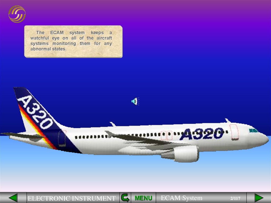
The ECAM system keeps awatchful eye on all of the aircraft
systems monitoring them for any
abnormal states.
ELECTRONIC INSTRUMENT
MENU
ECAM System
2/117
3.
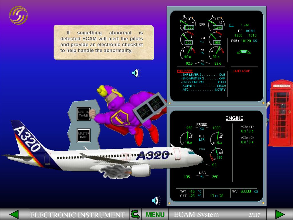
Ifsomething
abnormal
is
detected ECAM will alert the pilots
and provide an electronic checklist
to help handle the abnormality.
ELECTRONIC INSTRUMENT
MENU
ECAM System
3/117
4.
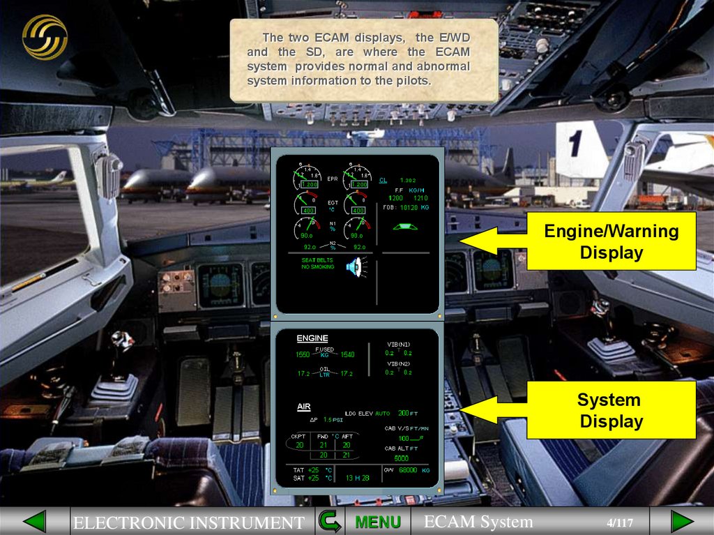
The two ECAM displays, the E/WDand the SD, are where the ECAM
system provides normal and abnormal
system information to the pilots.
Engine/Warning
Display
System
Display
ELECTRONIC INSTRUMENT
MENU
ECAM System
4/117
5.
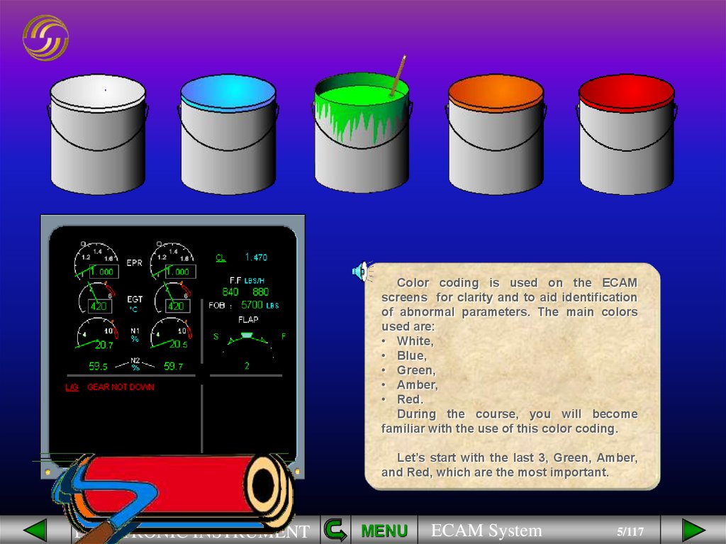
Color coding is used on the ECAMscreens for clarity and to aid identification
of abnormal parameters. The main colors
used are:
• White,
• Blue,
• Green,
• Amber,
• Red.
During the course, you will become
familiar with the use of this color coding.
Let’s start with the last 3, Green, Amber,
and Red, which are the most important.
ELECTRONIC INSTRUMENT
MENU
ECAM System
5/117
6.
Green color coding is used toindicate a normal condition. Notice
that on the E/WD and the SD shown,
all indications are normal.
= NORMAL
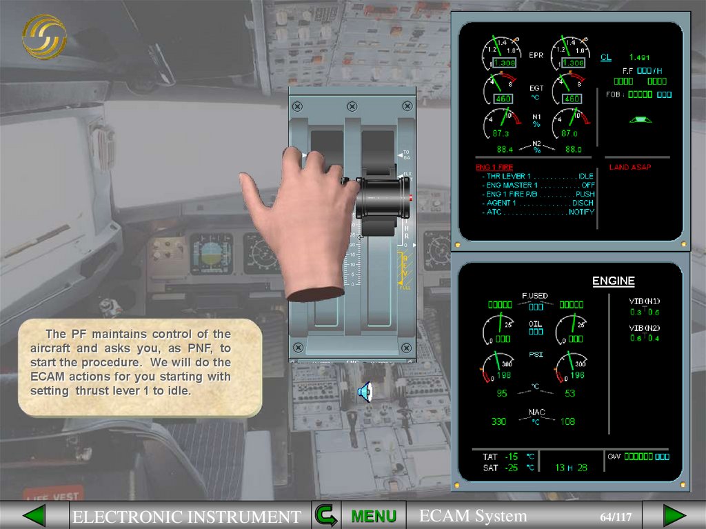
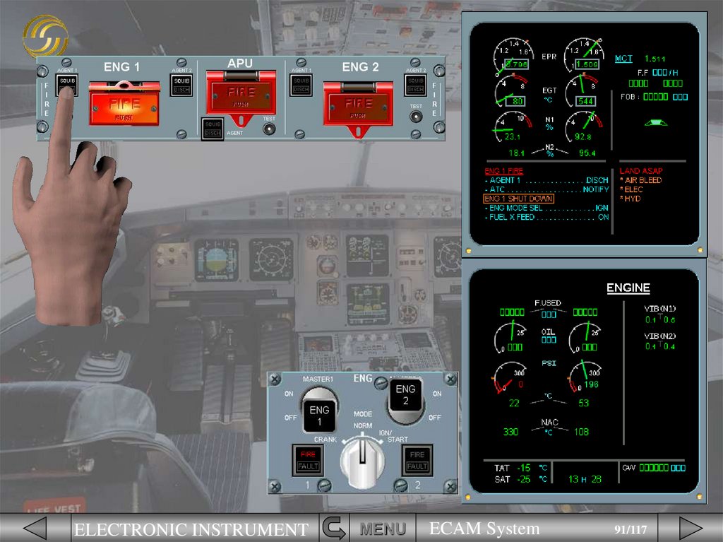
ELECTRONIC INSTRUMENT
MENU
ECAM System
6/117
7.
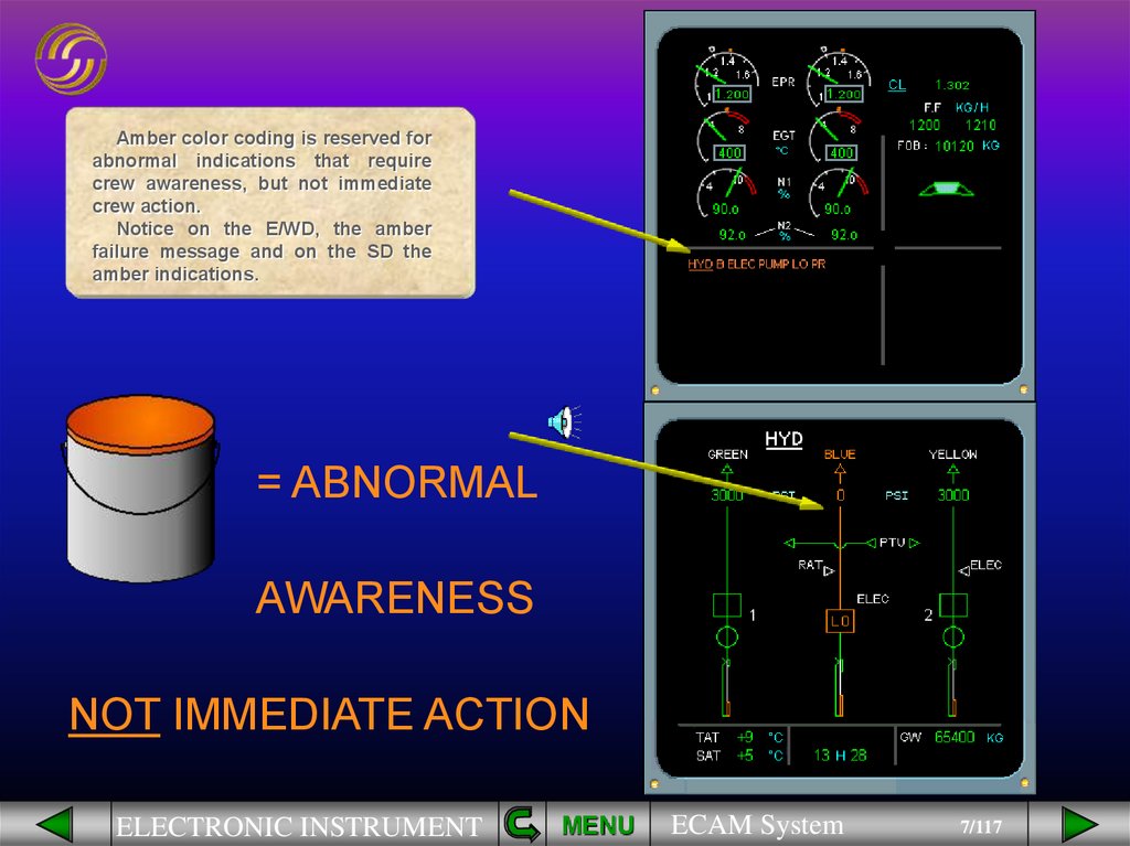
Amber color coding is reserved forabnormal indications that require
crew awareness, but not immediate
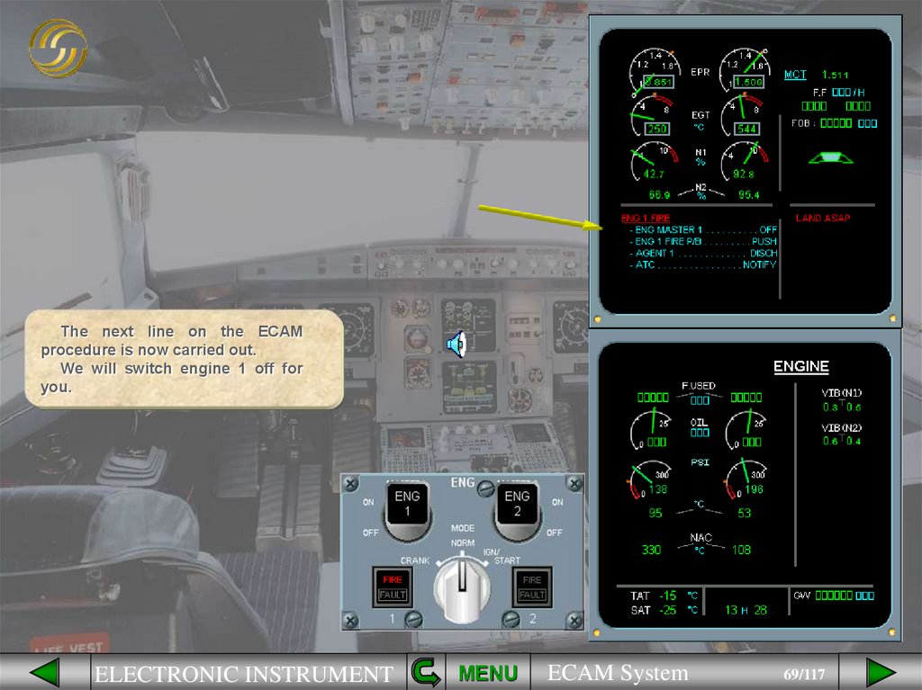
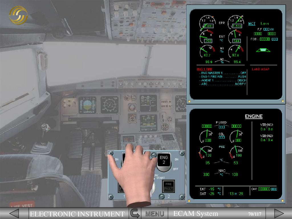
crew action.
Notice on the E/WD, the amber
failure message and on the SD the
amber indications.
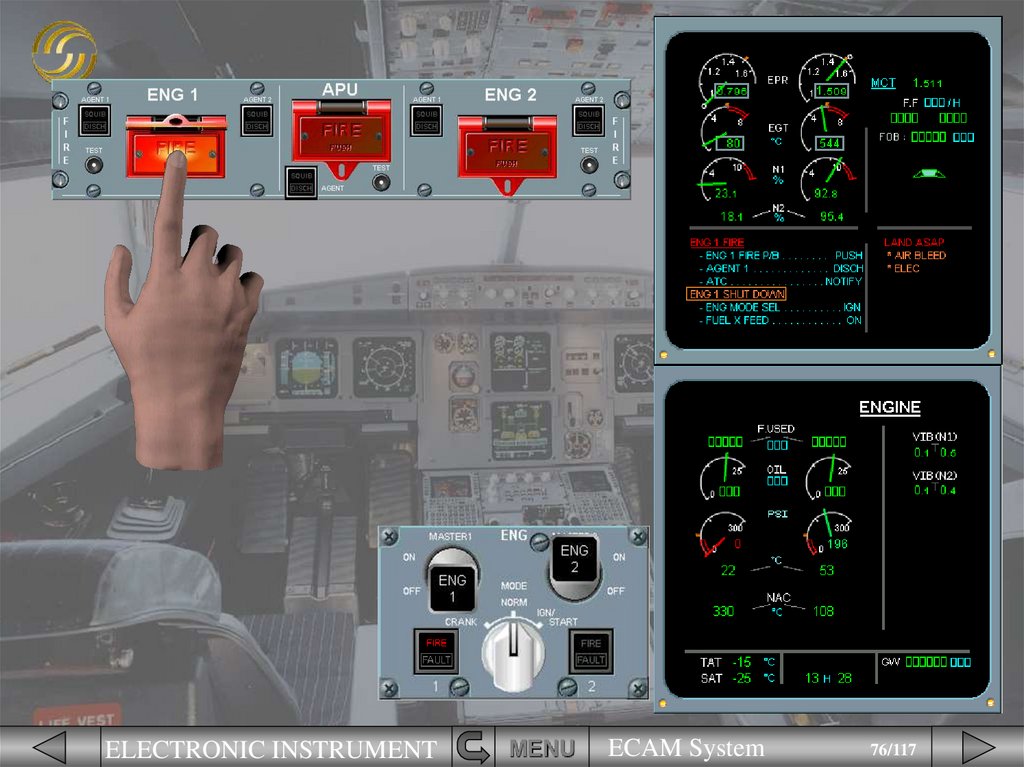
= ABNORMAL
AWARENESS
NOT IMMEDIATE ACTION
ELECTRONIC INSTRUMENT
MENU
ECAM System
7/117
8.
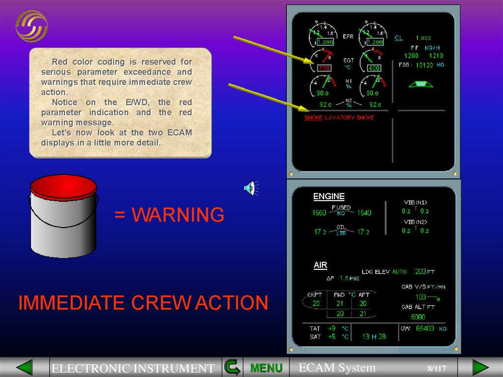
Red color coding is reserved forserious parameter exceedance and
warnings that require immediate crew
action.
Notice on the E/WD, the red
parameter indication and the red
warning message.
Let’s now look at the two ECAM
displays in a little more detail.
= WARNING
IMMEDIATE CREW ACTION
ELECTRONIC INSTRUMENT
MENU
ECAM System
8/117
9.
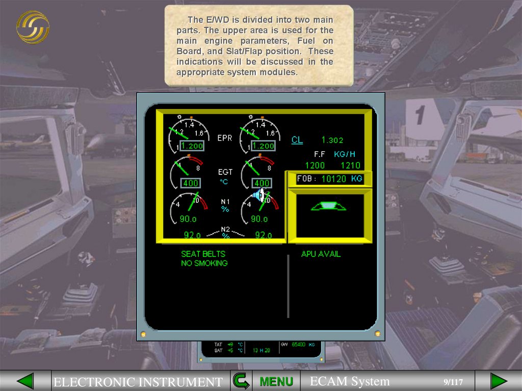
The E/WD is divided into two mainparts. The upper area is used for the
main engine parameters, Fuel on
Board, and Slat/Flap position. These
indications will be discussed in the
appropriate system modules.
ELECTRONIC INSTRUMENT
MENU
ECAM System
9/117
10.
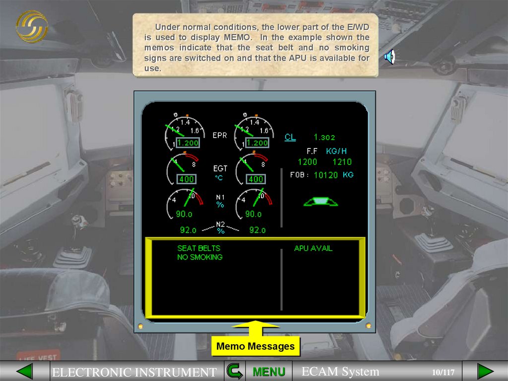
Under normal conditions, the lower part of the E/WDis used to display MEMO. In the example shown the
memos indicate that the seat belt and no smoking
signs are switched on and that the APU is available for
use.
Memo Messages
ELECTRONIC INSTRUMENT
MENU
ECAM System
10/117
11.
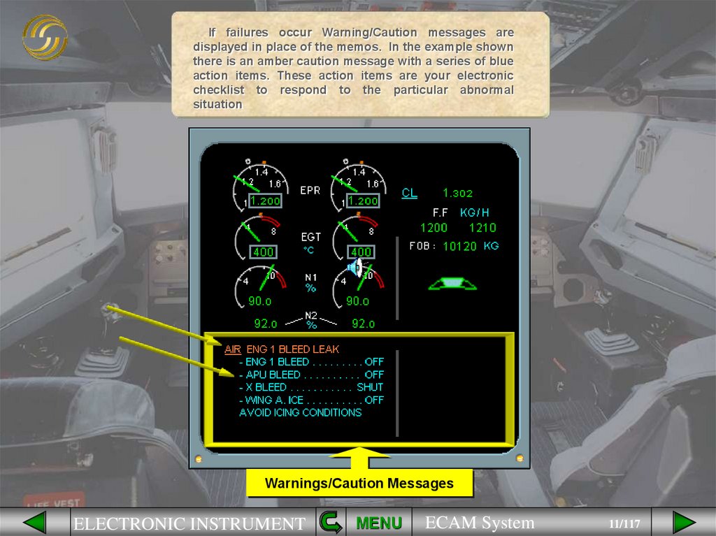
If failures occur Warning/Caution messages aredisplayed in place of the memos. In the example shown
there is an amber caution message with a series of blue
action items. These action items are your electronic
checklist to respond to the particular abnormal
situation
Warnings/Caution Messages
ELECTRONIC INSTRUMENT
MENU
ECAM System
11/117
12.
The SD is used to display particular system information. In the exampleshown the CRUISE page is displayed. This is the page normally seen for the
majority of the time that the aircraft is airborne. Information, that is useful
during flight, from several systems is displayed.
The individual indications will be covered in the appropriate system
modules.
CRUISE
Page
ELECTRONIC INSTRUMENT
MENU
ECAM System
12/117
13.
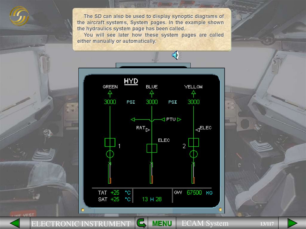
The SD can also be used to display synoptic diagrams ofthe aircraft systems, System pages. In the example shown
the hydraulics system page has been called.
You will see later how these system pages are called
either manually or automatically.
ELECTRONIC INSTRUMENT
MENU
ECAM System
13/117
14.
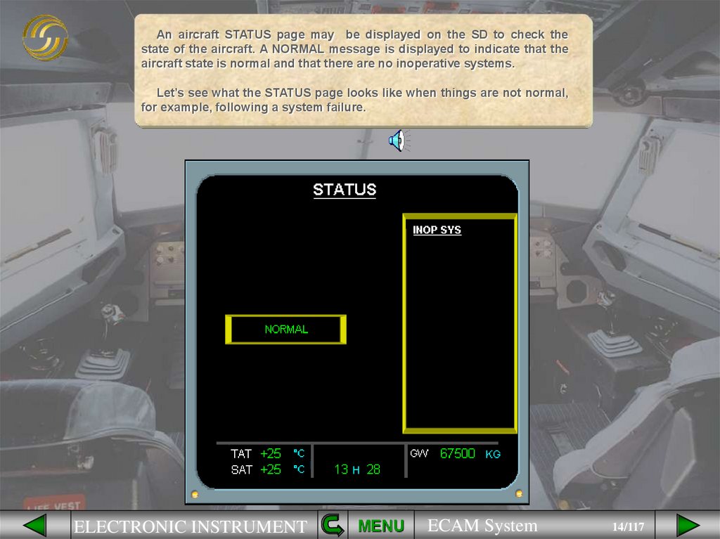
An aircraft STATUS page may be displayed on the SD to check thestate of the aircraft. A NORMAL message is displayed to indicate that the
aircraft state is normal and that there are no inoperative systems.
Let’s see what the STATUS page looks like when things are not normal,
for example, following a system failure.
ELECTRONIC INSTRUMENT
MENU
ECAM System
14/117
15.
LimitationsELECTRONIC INSTRUMENT
MENU
ECAM System
15/117
16.
LimitationsApproach
Procedures
ELECTRONIC INSTRUMENT
MENU
ECAM System
16/117
17.
LimitationsApproach
Procedures
Information
ELECTRONIC INSTRUMENT
MENU
ECAM System
17/117
18.
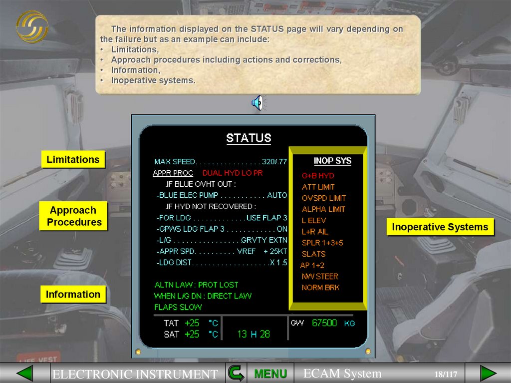
The information displayed on the STATUS page will vary depending onthe failure but as an example can include:
• Limitations,
• Approach procedures including actions and corrections,
• Information,
• Inoperative systems.
Limitations
Approach
Procedures
Inoperative Systems
Information
ELECTRONIC INSTRUMENT
MENU
ECAM System
18/117
19.
The area at the bottom of any SDcontains permanent data:
• Total Air Temperature (TAT),
• Static Air Temperature (SAT),
• Time,
• Gross Weight.
ELECTRONIC INSTRUMENT
MENU
ECAM System
19/117
20.
Individual airlines can choose which units they wish to use forcertain parameters on the ECAM screens. In the examples shown we
have highlighted the areas on the screens where the units used differ.
US UNITS
ELECTRONIC INSTRUMENT
METRIC UNITS
MENU
ECAM System
20/117
21.
Because these indications are only mentioned in a few areas of theground school course, we will use boxes to indicate that the units may
differ depending on your airlines’ choice. The boxes mean that the
information in this area of the screen is irrelevant to the system being
studied. When a system, for example Fuel, is being studied then
appropriate unit values will be shown.
US UNITS
ELECTRONIC INSTRUMENT
METRIC UNITS
MENU
ECAM System
21/117
22.
Under normal conditions theECAM system provides the pilots
with the information that they “Need
to Know” for the particular phase of
flight, no more no less.
As an example during the
approach when the landing gear is
extended the ECAM WHEEL system
page is automatically displayed.
ELECTRONIC INSTRUMENT
MENU
ECAM System
22/117
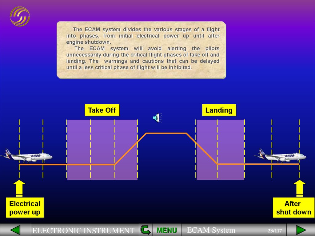
23.
The ECAM system divides the various stages of a flightinto phases, from initial electrical power up until after
engine shutdown.
The ECAM system will avoid alerting the pilots
unnecessarily during the critical flight phases of take off and
landing. The warnings and cautions that can be delayed
until a less critical phase of flight will be inhibited.
Take Off
Landing
Electrical
power up
ELECTRONIC INSTRUMENT
After
shut down
MENU
ECAM System
23/117
24.
We will now look at the differentways that the ECAM system advises
you when things are not going
exactly right. We will start with a
minor advice indication and work up
to a major fault, concentrating on the
two ECAM screens.
ELECTRONIC INSTRUMENT
MENU
ECAM System
24/117
25.
If a system parameter, for example anengine vibration level, approaches a limit
the ECAM system will advise you of this
by displaying the relevant system page on
the SD. The affected parameter will pulse.
Notice that at this stage, the parameter is
still shown in green since it is still within
normal limits.
This is known as an ECAM ADVISORY.
Now let’s look at what happens when
ECAM detects a minor system failure.
ELECTRONIC INSTRUMENT
MENU
ECAM System
25/117
26.
When a failure occurs leading to aloss of redundancy or loss of a
system that does not affect the safety
of the flight, for example DFDR
FAULT, the ECAM system will inform
you by displaying an amber
CAUTION message on the E/WD.
At the same time the two CLEAR
keys on the ECAM control panel will
illuminate.
ELECTRONIC INSTRUMENT
MENU
ECAM System
26/117
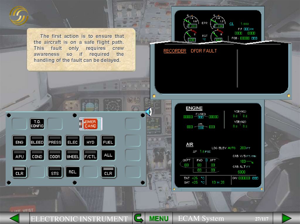
27.
The first action is to ensure thatthe aircraft is on a safe flight path.
This fault only requires crew
awareness so if required the
handling of the fault can be delayed.
ELECTRONIC INSTRUMENT
MENU
ECAM System
27/117
28.
Normally the PNF carries out theECAM procedure while the PF is
responsible for the aircraft flight
path. For this exercise you are the
PNF.
Read the title of the failure, in this
case “RECORDER DFDR FAULT”.
The PF will ask you to perform
ECAM actions.
ELECTRONIC INSTRUMENT
MENU
ECAM System
28/117
29.
In this case there are no actionsrequired so, after confirmation from
the PF, the caution message can be
cleared by pressing one of the
CLEAR keys on the ECAM Control
Panel.
Press a CLEAR key
ELECTRONIC INSTRUMENT
MENU
ECAM System
29/117
30.
As a result of pressing eitherCLEAR key the Caution message has
been cleared from the E/WD and the
STATUS
page
is
displayed
automatically.
In this example you can see that
the inoperative system is the DFDR.
ELECTRONIC INSTRUMENT
MENU
ECAM System
30/117
31.
On the ECAM control panel theSTATUS key is illuminated along with
the two CLEAR keys.
When safe to do so the STATUS
page is reviewed by both pilots. After
confirmation from the PF the STATUS
page is cleared by pressing either the
STS key or one of the CLR keys.
Clear the STATUS page
ELECTRONIC INSTRUMENT
MENU
ECAM System
31/117
32.
Notice that:• on the E/WD there is a boxed STS
caption to tell you that there is
information on the STATUS page,
• on the ECAM control panel there
are no lights.
The ECAM actions for the DFDR
fault are complete.
ELECTRONIC INSTRUMENT
MENU
ECAM System
32/117
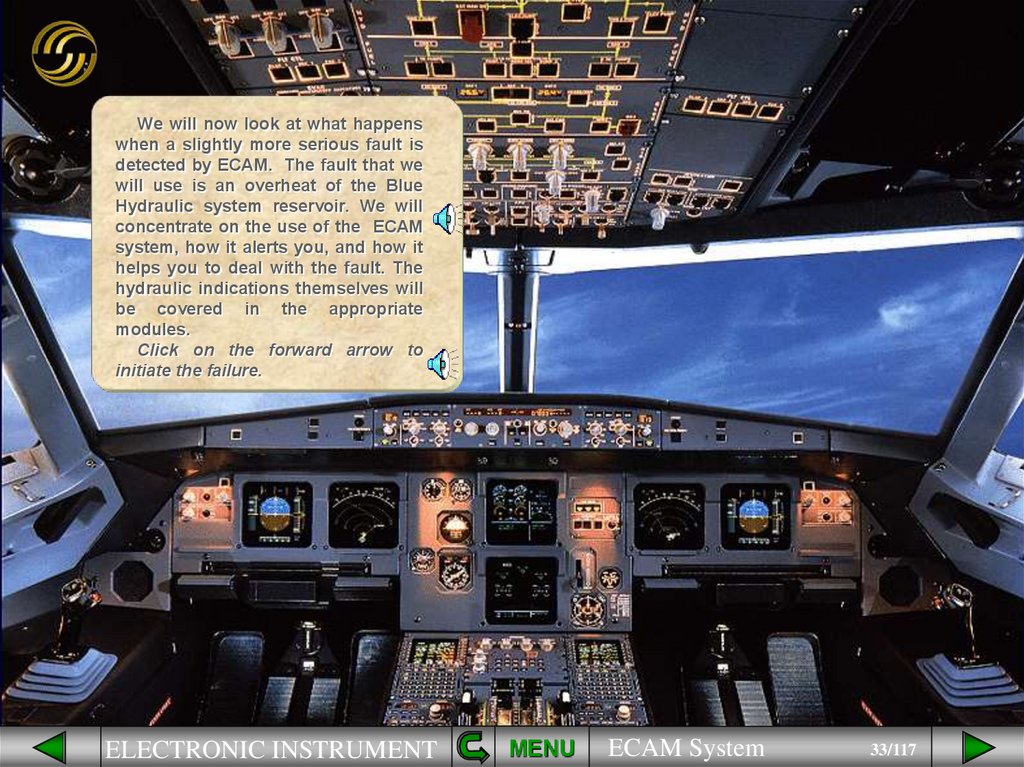
33.
We will now look at what happenswhen a slightly more serious fault is
detected by ECAM. The fault that we
will use is an overheat of the Blue
Hydraulic system reservoir. We will
concentrate on the use of the ECAM
system, how it alerts you, and how it
helps you to deal with the fault. The
hydraulic indications themselves will
be covered in the appropriate
modules.
Click on the forward arrow to
initiate the failure.
ELECTRONIC INSTRUMENT
MENU
ECAM System
33/117
34.
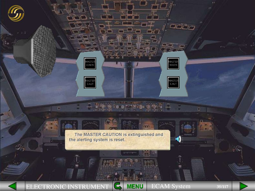
When the fault occurs the ECAM systemalerts the crew aurally and visually. You will
hear a single chime and see the MASTER
CAUTION lights. To cancel the MASTER
CAUTION lights, and reset the alerting system,
one of the MASTER CAUTION pb must be
pressed.
Extinguish the Master Caution light
ELECTRONIC INSTRUMENT
MENU
ECAM System
34/117
35.
The MASTER CAUTION is extinguished andthe alerting system is reset.
ELECTRONIC INSTRUMENT
MENU
ECAM System
35/117
36.
= ABNORMALAWARENESS
NOT IMMEDIATE ACTION
The first priority is always to ensure the safe
flight path of the aircraft before dealing with the
fault. The MASTER CAUTION means that the
abnormal situation needs crew awareness but
not immediate action.
ELECTRONIC INSTRUMENT
MENU
ECAM System
36/117
37.
The indications are:• A failure message on the E/WD,
• The system synoptic associated
with the fault is automatically
displayed on the SD,
• The Clear keys on the ECAM
control panel light up.
ELECTRONIC INSTRUMENT
MENU
ECAM System
37/117
38.
Let’s study the details on the E/WDfirst. The system title is underlined,
in this case HYDraulics, and the fault
is shown alongside, Blue ReSerVoiR
OVerHeaT. Notice that abbreviations
are used.
ELECTRONIC INSTRUMENT
MENU
ECAM System
38/117
39.
If you look carefully at theHydraulic system display you will
notice an amber OVHT message is
displayed. This abnormal indication
is how the fault is shown on the
system synoptic.
ELECTRONIC INSTRUMENT
MENU
ECAM System
39/117
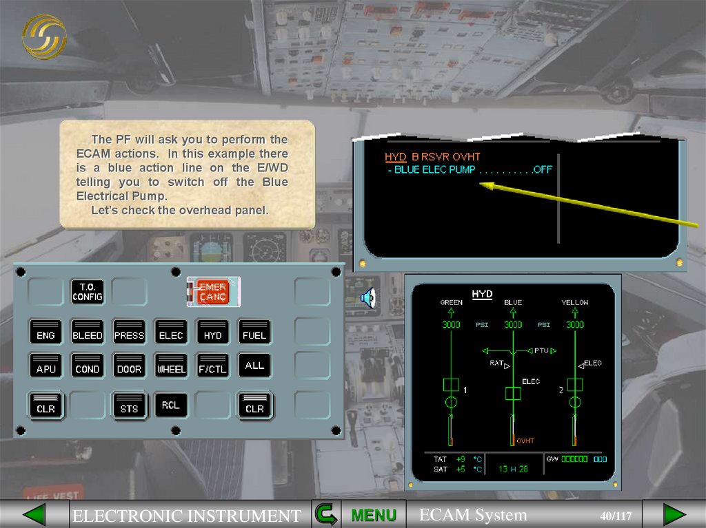
40.
The PF will ask you to perform theECAM actions. In this example there
is a blue action line on the E/WD
telling you to switch off the Blue
Electrical Pump.
Let’s check the overhead panel.
ELECTRONIC INSTRUMENT
MENU
ECAM System
40/117
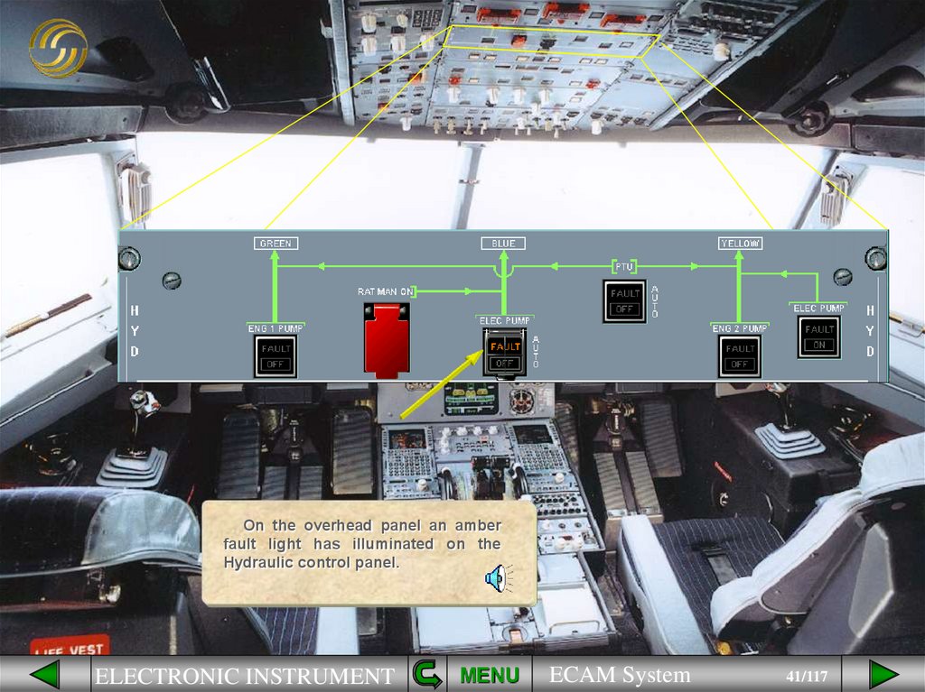
41.
On the overhead panel an amberfault light has illuminated on the
Hydraulic control panel.
ELECTRONIC INSTRUMENT
MENU
ECAM System
41/117
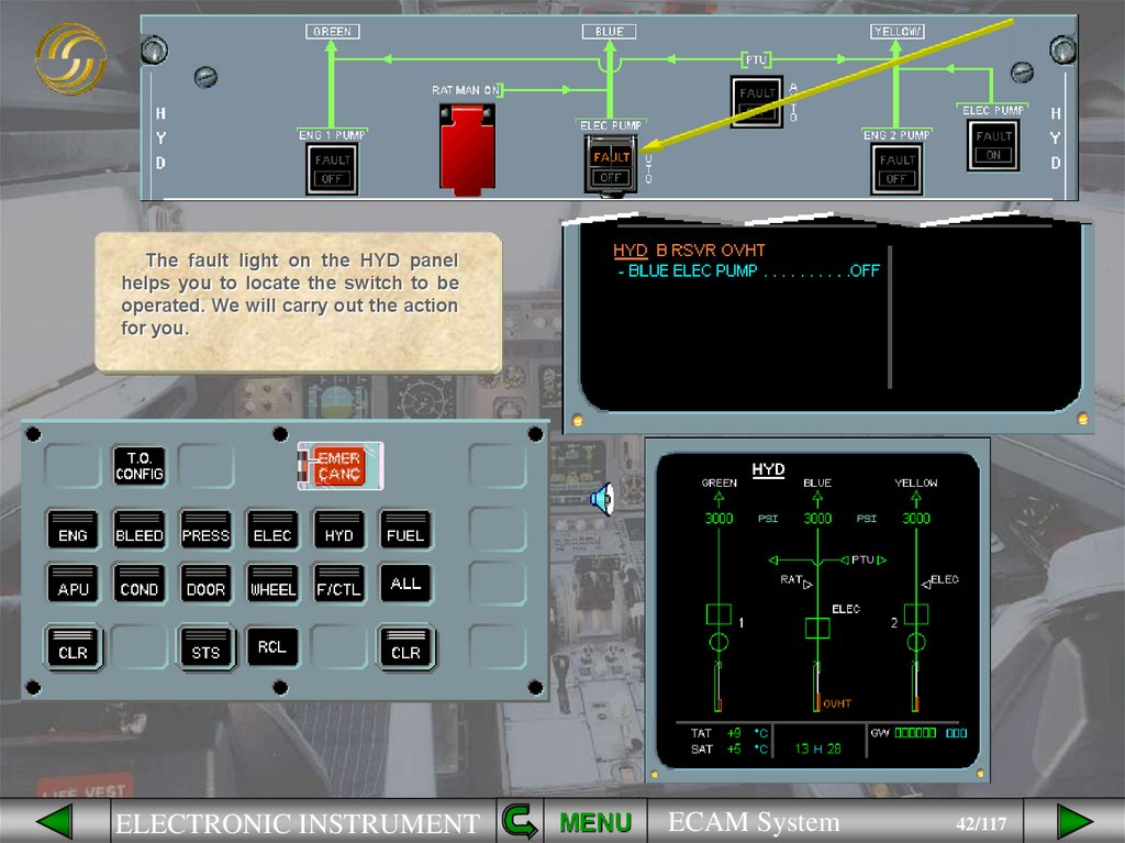
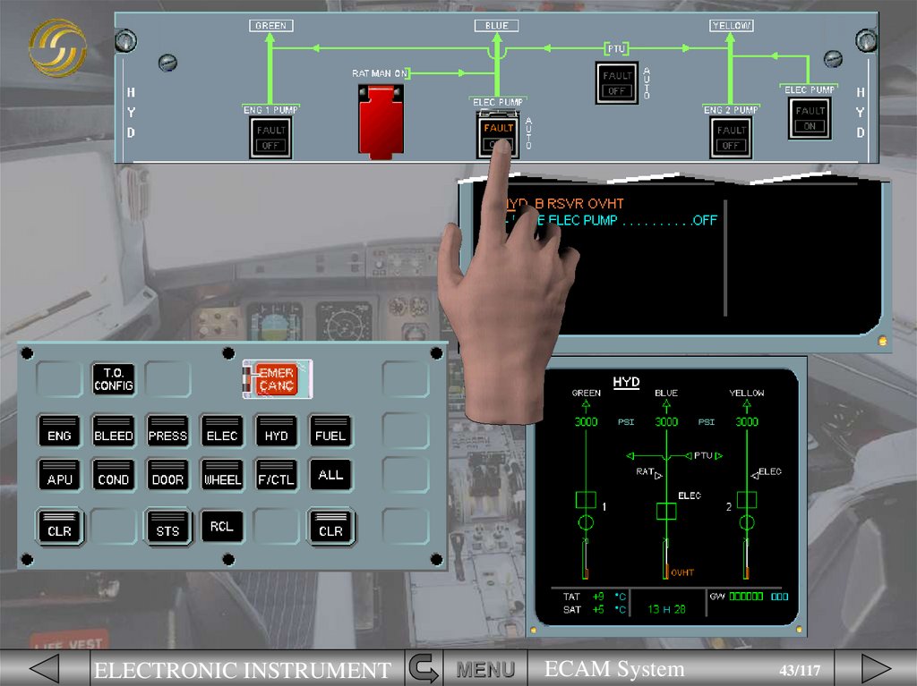
42.
The fault light on the HYD panelhelps you to locate the switch to be
operated. We will carry out the action
for you.
ELECTRONIC INSTRUMENT
MENU
ECAM System
42/117
43.
ELECTRONIC INSTRUMENTMENU
ECAM System
43/117
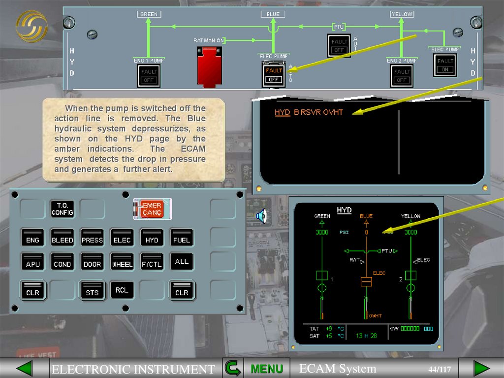
44.
When the pump is switched off theaction line is removed. The Blue
hydraulic system depressurizes, as
shown on the HYD page by the
amber indications.
The
ECAM
system detects the drop in pressure
and generates a further alert.
ELECTRONIC INSTRUMENT
MENU
ECAM System
44/117
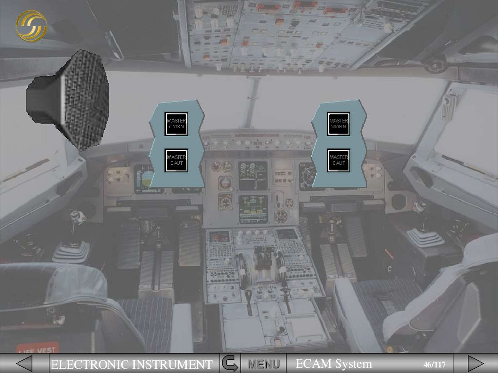
45.
You hear the chime and see the MasterCaution lights.
Extinguish the Master Caution lights
ELECTRONIC INSTRUMENT
MENU
ECAM System
45/117
46.
ELECTRONIC INSTRUMENTMENU
ECAM System
46/117
47.
There is now a new abnormalmessage on the E/WD , B SYS LO PR.
The message is boxed to indicate
that the loss of the blue hydraulic
system is classed as a Primary
failure that will affect other systems.
ELECTRONIC INSTRUMENT
MENU
ECAM System
47/117
48.
The systems affected are shownon the right of the E/WD as starred
items called Secondary failures.
In this example the Primary failure
of the Blue hydraulic system has
caused a Secondary failure of Flight
Controls.
ELECTRONIC INSTRUMENT
MENU
ECAM System
48/117
49.
After review and confirmation fromthe PF the Hydraulic failure message
on the E/WD can be cleared.
Clear the HYDRAULICS message.
ELECTRONIC INSTRUMENT
MENU
ECAM System
49/117
50.
Notice that normal memos havereturned on the left side of the E/WD.
The ECAM F/CTL system page is
displayed
on
the
SD
which
corresponds to the secondary failure
item on the E/WD .
ELECTRONIC INSTRUMENT
MENU
ECAM System
50/117
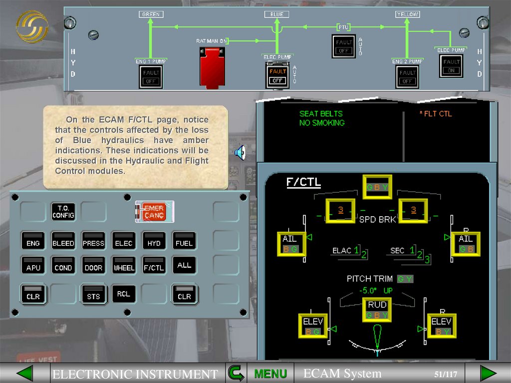
51.
On the ECAM F/CTL page, noticethat the controls affected by the loss
of Blue hydraulics have amber
indications. These indications will be
discussed in the Hydraulic and Flight
Control modules.
ELECTRONIC INSTRUMENT
MENU
ECAM System
51/117
52.
After review and confirmation fromthe PF the Flight Control secondary
failure message can be cleared.
Clear F/CTL
ELECTRONIC INSTRUMENT
MENU
ECAM System
52/117
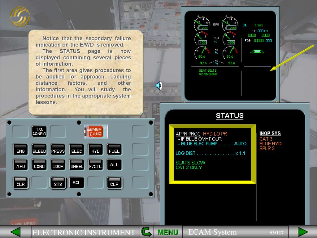
53.
Notice that the secondary failureindication on the E/WD is removed.
The STATUS page is now
displayed containing several pieces
of information.
The first area gives procedures to
be applied for approach, Landing
distance
factors,
and
other
information.
You will study the
procedures in the appropriate system
lessons.
ELECTRONIC INSTRUMENT
MENU
ECAM System
53/117
54.
In this example the inoperativesystems are:
• CAT 3, which means that Category
3 autoland is not available,
• BLUE HYD, the system was
switched off during the ECAM
procedure,
• SPLR 3, the spoilers that are
inoperative because there is no blue
hydraulic pressure.
ELECTRONIC INSTRUMENT
MENU
ECAM System
54/117
55.
The STATUS page is reviewed byboth pilots. After confirmation from
the PF the STATUS page can be
cleared.
Clear the STATUS page
ELECTRONIC INSTRUMENT
MENU
ECAM System
55/117
56.
The ECAM actions for a BlueHydraulic Reservoir Overheat are
complete. Notice that the STATUS
reminder is displayed at the bottom
of the E/WD reminding you that there
is information on the STATUS page.
This is important since there were
approach procedures to be applied.
ELECTRONIC INSTRUMENT
MENU
ECAM System
56/117
57.
If it contains information, theECAM system automatically recalls
the STATUS page
during the
approach phase when the slats are
extended. This is done so that if
there are any items affecting the
approach and landing they will be
presented to you at an early stage.
You can see that in the example
shown
there
are
approach
procedures. You will see how these
approach procedures are applied
later in the course.
Clear the STATUS page.
ELECTRONIC INSTRUMENT
MENU
ECAM System
57/117
58.
The STATUS page is cleared andthe CRUISE page is displayed.
ELECTRONIC INSTRUMENT
MENU
ECAM System
58/117
59.
So far we have looked at how the ECAM system advises you of minor failures.We will now look at what happens when there is a serious failure that requires
immediate action. To demonstrate this we will use an Engine Fire. As before we
will not concentrate on the system failure but on ECAM indications and
procedures.
Be ready to cancel the warning by pressing a MASTER WARNING pb.
Click on the forward arrow to initiate the failure.
= WARNING
IMMEDIATE CREW ACTION
ELECTRONIC INSTRUMENT
MENU
ECAM System
59/117
60.
ELECTRONIC INSTRUMENTMENU
ECAM System
60/117
61.
When the fault occurs the ECAM systemalerts the crew aurally and visually. You hear a
continuous repetitive chime and see the
MASTER WARNING lights flashing. Press one
of the the MASTER WARNING pb to:
• cancel the MASTER WARNING lights,
• stop the chimes,
• reset the alerting system.
ELECTRONIC INSTRUMENT
MENU
ECAM System
61/117
62.
On the E/WD the red messageENG 1 FIRE and the associated
procedure are displayed.
The red indications on the FIRE
panel and the ENG panel provide
confirmation and identification of
the affected engine.
The
ENGINE
page
has
automatically been called on the
SD, and in this example the nacelle
temperature is pulsing.
ELECTRONIC INSTRUMENT
MENU
ECAM System
62/117
63.
Notice that there is a red LANDASAP message on the E/WD. This
means that ECAM has determined
that the fault detected is serious
enough to require a landing as
soon as possible.
ELECTRONIC INSTRUMENT
MENU
ECAM System
63/117
64.
The PF maintains control of theaircraft and asks you, as PNF, to
start the procedure. We will do the
ECAM actions for you starting with
setting thrust lever 1 to idle.
ELECTRONIC INSTRUMENT
MENU
ECAM System
64/117
65.
ELECTRONIC INSTRUMENTMENU
ECAM System
65/117
66.
ELECTRONIC INSTRUMENTMENU
ECAM System
66/117
67.
ELECTRONIC INSTRUMENTMENU
ECAM System
67/117
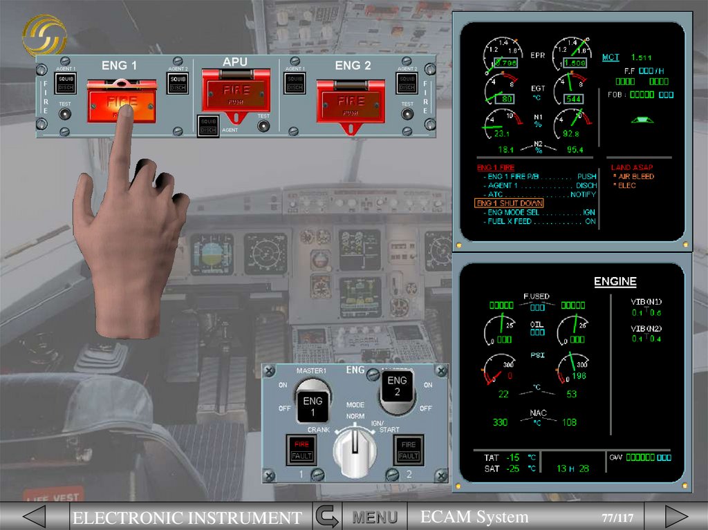
68.
ELECTRONIC INSTRUMENTMENU
ECAM System
68/117
69.
The next line on the ECAMprocedure is now carried out.
We will switch engine 1 off for
you.
ELECTRONIC INSTRUMENT
MENU
ECAM System
69/117
70.
ELECTRONIC INSTRUMENTMENU
ECAM System
70/117
71.
ELECTRONIC INSTRUMENTMENU
ECAM System
71/117
72.
ELECTRONIC INSTRUMENTMENU
ECAM System
72/117
73.
After switching ENG 1 off, theafter
ENG
1
SHUT
DOWN
procedure is shown on the E/WD.
Notice that the amber caution
message has appeared below the
red warning. This happens because
you have to finish the engine fire
procedure before carrying out the
actions for ENG 1 SHUTDOWN. The
ECAM system has automatically
allocated priority to the warning.
ELECTRONIC INSTRUMENT
MENU
ECAM System
73/117
74.
As a result of switching off theengine there are now secondary
failures.
ELECTRONIC INSTRUMENT
MENU
ECAM System
74/117
75.
The next ECAM action is to pushthe engine 1 fire pb. We will do this
for you.
ELECTRONIC INSTRUMENT
MENU
ECAM System
75/117
76.
ELECTRONIC INSTRUMENTMENU
ECAM System
76/117
77.
ELECTRONIC INSTRUMENTMENU
ECAM System
77/117
78.
ELECTRONIC INSTRUMENTMENU
ECAM System
78/117
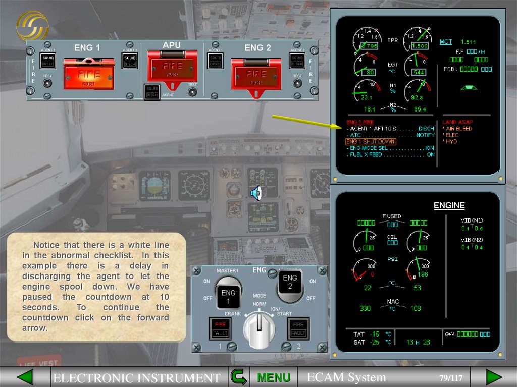
79.
Notice that there is a white linein the abnormal checklist. In this
example there is a delay in
discharging the agent to let the
engine spool down. We have
paused the countdown at 10
seconds.
To
continue
the
countdown click on the forward
arrow.
ELECTRONIC INSTRUMENT
MENU
ECAM System
79/117
80.
ELECTRONIC INSTRUMENTMENU
ECAM System
80/117
81.
ELECTRONIC INSTRUMENTMENU
ECAM System
81/117
82.
ELECTRONIC INSTRUMENTMENU
ECAM System
82/117
83.
ELECTRONIC INSTRUMENTMENU
ECAM System
83/117
84.
ELECTRONIC INSTRUMENTMENU
ECAM System
84/117
85.
ELECTRONIC INSTRUMENTMENU
ECAM System
85/117
86.
ELECTRONIC INSTRUMENTMENU
ECAM System
86/117
87.
ELECTRONIC INSTRUMENTMENU
ECAM System
87/117
88.
ELECTRONIC INSTRUMENTMENU
ECAM System
88/117
89.
ELECTRONIC INSTRUMENTMENU
ECAM System
89/117
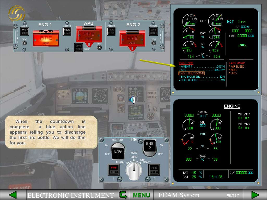
90.
Whenthe
countdown
is
complete
a blue action line
appears telling you to discharge
the first fire bottle. We will do this
for you.
ELECTRONIC INSTRUMENT
MENU
ECAM System
90/117
91.
ELECTRONIC INSTRUMENTMENU
ECAM System
91/117
92.
The next action line is to notifyATC.
Since the ECAM system can not
tell when you are talking there is no
feedback so this line will not
disappear.
ELECTRONIC INSTRUMENT
MENU
ECAM System
92/117
93.
Notice that we still have a red fireindication which means that the fire
is
not
extinguished.
Another
condition line has appeared and a
second countdown automatically
starts. This one is 30 seconds long.
We have paused the countdown.
To continue the countdown click
on the forward arrow.
ELECTRONIC INSTRUMENT
MENU
ECAM System
93/117
94.
ELECTRONIC INSTRUMENTMENU
ECAM System
94/117
95.
ELECTRONIC INSTRUMENTMENU
ECAM System
95/117
96.
ELECTRONIC INSTRUMENTMENU
ECAM System
96/117
97.
ELECTRONIC INSTRUMENTMENU
ECAM System
97/117
98.
Agent 1 managed to extinguish thefire. The countdown for agent 2
stopped immediately.
Notice that:
• the ENG FIRE procedure on the
ECAM disappeared. This means the
fire is out,
• the local warnings on the FIRE
panel and the ENG panel are no
longer illuminated, confirming that
the fire is out,
• LAND ASAP has changed from
red to amber which means that ECAM
has determined that the fault is less
critical, but still requires a landing as
soon as possible.
ELECTRONIC INSTRUMENT
MENU
ECAM System
98/117
99.
The remaining steps are similar tothose seen for an ECAM CAUTION
so we will stop here.
You have seen that the ECAM
system has provided a smart and
interactive checklist to help you deal
with a major problem.
ELECTRONIC INSTRUMENT
MENU
ECAM System
99/117
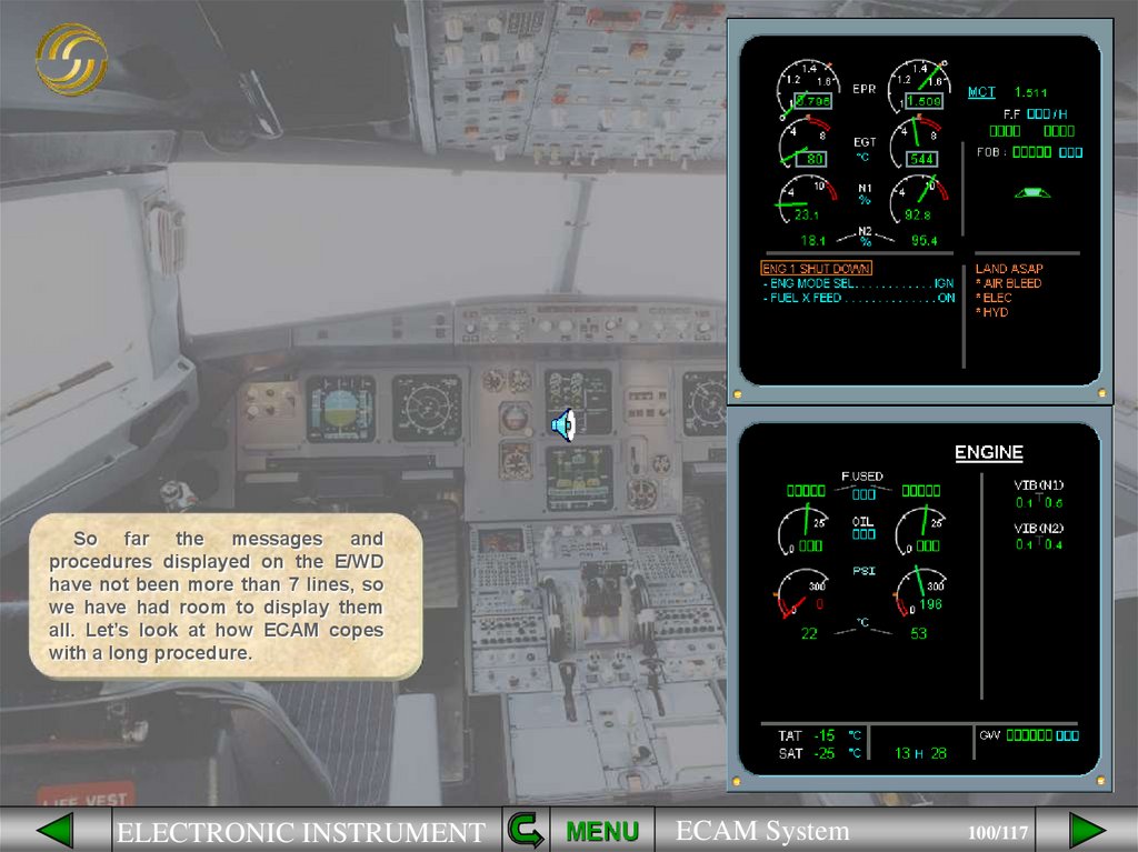
100.
So far the messages andprocedures displayed on the E/WD
have not been more than 7 lines, so
we have had room to display them
all. Let’s look at how ECAM copes
with a long procedure.
ELECTRONIC INSTRUMENT
MENU
ECAM System
100/117
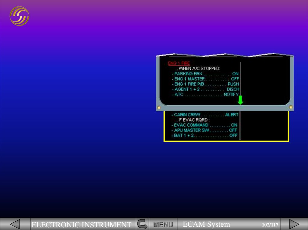
101.
In this example of the indications foran engine fire on the ground there is an
overflow arrow to indicate that there is
more information to be seen.
For training purposes we have shown
the rest of the procedure below the
E/WD.
We will complete the ECAM
actions and you will see the associated
line of the procedure disappear.
ELECTRONIC INSTRUMENT
MENU
ECAM System
101/117
102.
ELECTRONIC INSTRUMENTMENU
ECAM System
102/117
103.
ELECTRONIC INSTRUMENTMENU
ECAM System
103/117
104.
ELECTRONIC INSTRUMENTMENU
ECAM System
104/117
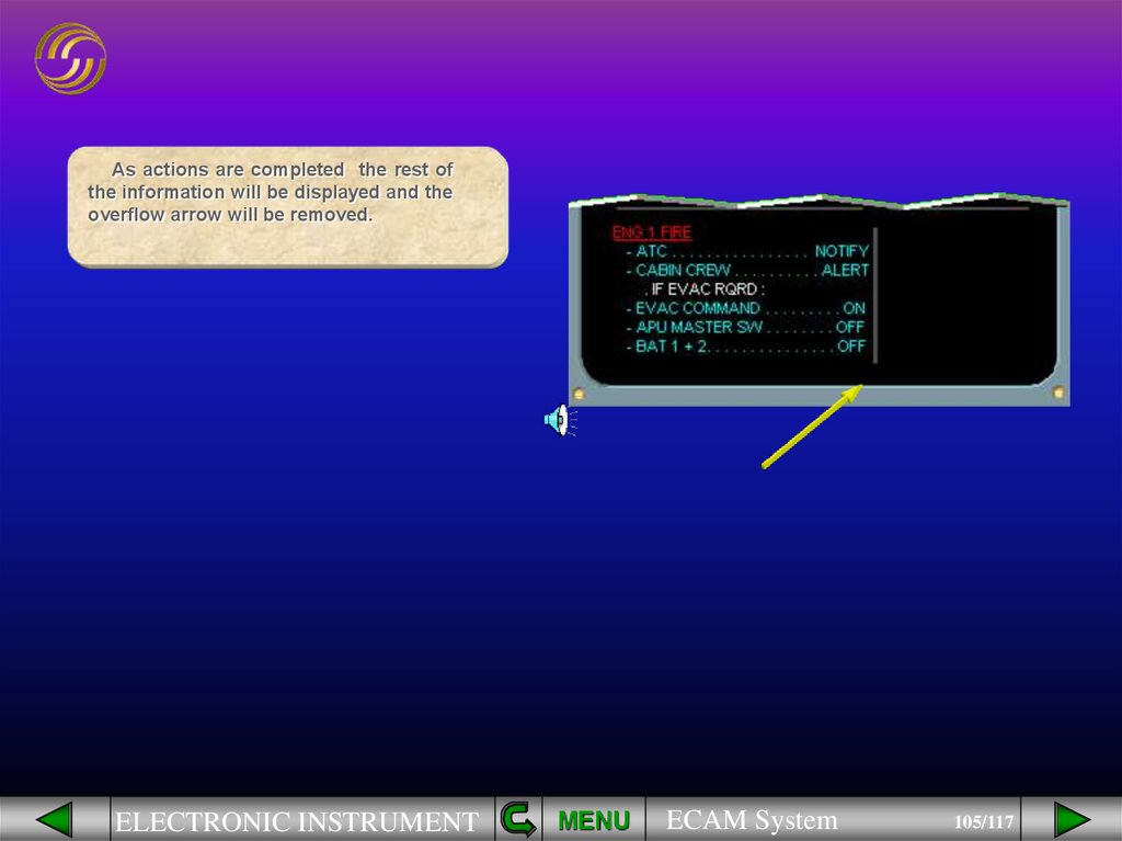
105.
As actions are completed the rest ofthe information will be displayed and the
overflow arrow will be removed.
ELECTRONIC INSTRUMENT
MENU
ECAM System
105/117
106.
On the STATUS page an overflowarrow also indicates that there is further
information to be seen on a second
page. By pressing a CLEAR key the
next page can be displayed.
Press a CLEAR key
ELECTRONIC INSTRUMENT
MENU
ECAM System
106/117
107.
The second page of STATUSinformation is displayed. Notice that the
list of inoperative systems has not
changed and that there is still an
overflow arrow.
Press a CLEAR key
ELECTRONIC INSTRUMENT
MENU
ECAM System
107/117
108.
The second page of inoperativesystems is displayed. There is still an
overflow arrow indicating that there is
more to be seen.
Press a CLEAR key
ELECTRONIC INSTRUMENT
MENU
ECAM System
108/117
109.
The last page of inoperative systemsis displayed and the overflow arrow is
removed.
If you want to display the
first
STATUS page again the STS key can be
pressed.
Press the STS key
ELECTRONIC INSTRUMENT
MENU
ECAM System
109/117
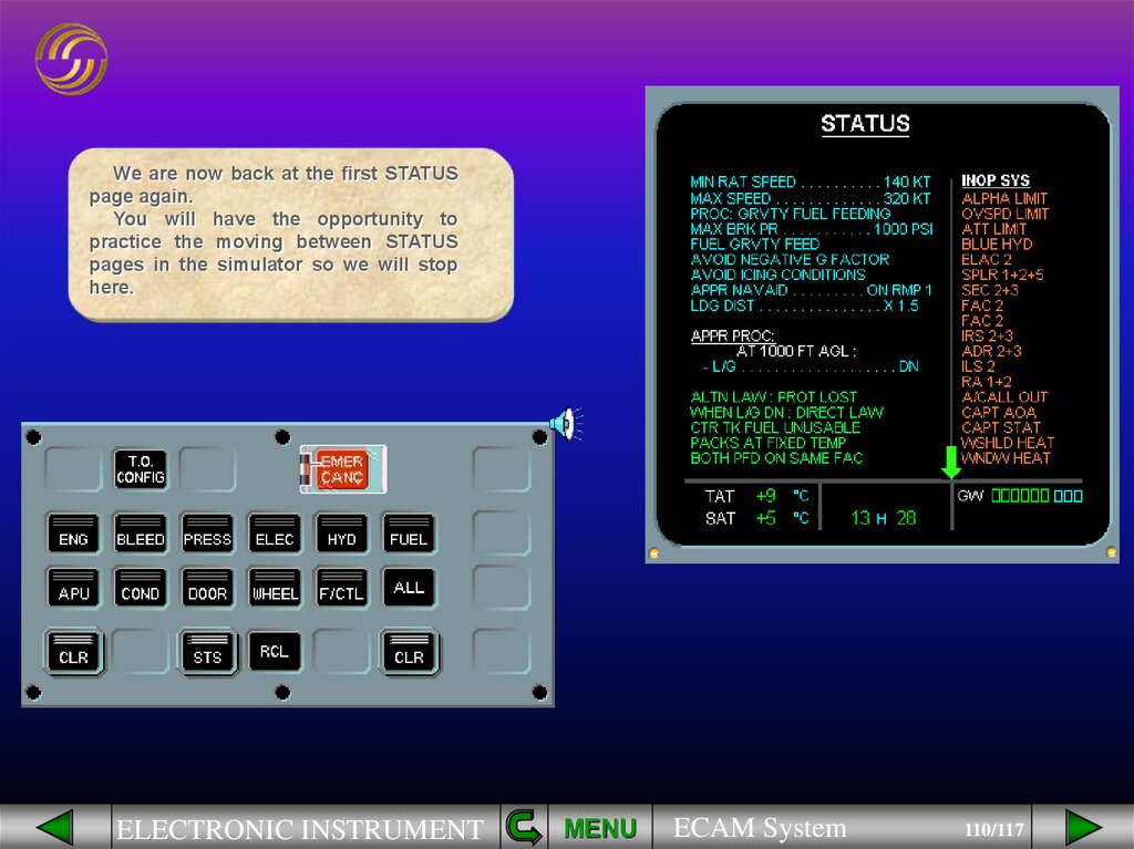
110.
We are now back at the first STATUSpage again.
You will have the opportunity to
practice the moving between STATUS
pages in the simulator so we will stop
here.
ELECTRONIC INSTRUMENT
MENU
ECAM System
110/117
111.
To summarize; initially you see all theinformation on the left side of the
STATUS page, and then all the
inoperative systems on the right.
ELECTRONIC INSTRUMENT
MENU
ECAM System
111/117
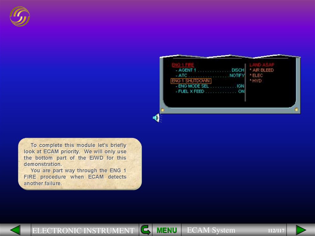
112.
To complete this module let’s brieflylook at ECAM priority. We will only use
the bottom part of the E/WD for this
demonstration.
You are part way through the ENG 1
FIRE procedure when ECAM detects
another failure.
ELECTRONIC INSTRUMENT
MENU
ECAM System
112/117
113.
The low priority RECORDER DFDRFAULT has appeared below the higher
priority ENG 1 FIRE and ENG 1
SHUTDOWN procedures.
Unfortunately it is one of those days
and another failure occurs.
ELECTRONIC INSTRUMENT
MENU
ECAM System
113/117
114.
The AP OFF warning has appearedabove the ENG 1 FIRE procedure. ECAM
has automatically assigned priority to
the AP OFF message because the first
priority is always to fly the aircraft!
ELECTRONIC INSTRUMENT
MENU
ECAM System
114/117
115.
The low priority RECORDER DFDRfault is now off the screen. You are
advised that the fault is there by the unstarred RECORDER text in the right
hand column of the E/WD and the green
overflow arrow.
We will clear the AUTO FLT AP OFF
warning for you.
ELECTRONIC INSTRUMENT
MENU
ECAM System
115/117
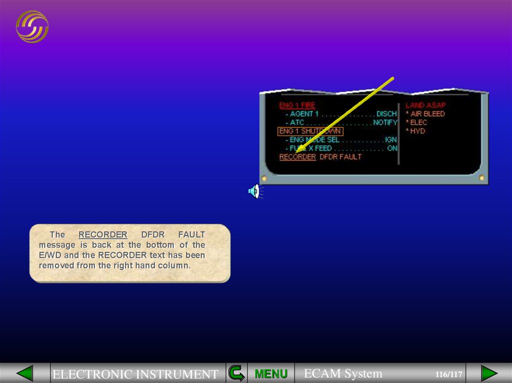
116.
TheRECORDER
DFDR
FAULT
message is back at the bottom of the
E/WD and the RECORDER text has been
removed from the right hand column.
ELECTRONIC INSTRUMENT
MENU
ECAM System
116/117
117.
In this module we have discussedthe ECAM system. You have seen the
various failure levels and how the ECAM
system alerts, indicates, and helps you
deal with a failure.
Throughout the ground school
course, and during your simulator
sessions, you will have the opportunity
to practice ECAM procedures.
Module Complete
ELECTRONIC INSTRUMENT
MENU
ECAM System
117/117
NEXT
118.
LIST OF SUBJECTSENGINE/WARNING DISPLAY
SYSTEM DISPLAY
FAILURE HANDLING
OVERFLOW ARROW
AUDIO
GLOSSARY
RETURN
ELECTRONIC INSTRUMENT
FCOM
EXIT
MENU
ECAM System
118/117