


")


")


")


 3.1")


")


 electronics
Similar presentations:


Training FM850
1.
TRAINING FM850Aarburg, Wednesday, November 15, 2017
2. FM850
FM850Participant:
2
John Do
Johny Does
Joe Did
Joey Dun
© Franke, www.franke.com
3. FM850
FM850TAKE CONTROL OF YOUR MACHINE
3
© Franke, www.franke.com
4. FM850 Overview
− Introduction− Technical construction
− Operation
− Programming
− Water flow circuit diagram
− Commissioning
− Product adjustment
− Troubleshooting
− Cleaning
4
© Franke, www.franke.com
5. FM850 Positioning/target groups
As with its predecessor the SpectraFoam Master, the FM850 serves as
a trendy drinks station without
losing any existing coffee
preparation expertise. Thanks to the
USP “dispensing hot and cold milk
foam in different automaticallyadjustable consistencies” the
FM850 is even more clearly setting
itself apart from traditional high-end
devices and the Spectra Foam
Master thanks to its wide range of
product specialties. The FM850 will
replace the Spectra Foam Master
on the basis of these strengths.
HoReCa
Corporate
coffee
QSR Industry
Food chain
C-stores
OEM ‘s
Coffee chain
Roasters
80 – 150 cups/day
150 – 250 cups/day
250+ cups/day
Supplementing the FM850 with the
Flavour Station add-on unit is
opening new doors in the world of
fully automatic beverage
preparation. You will not find
beverages quite like these
anywhere else on the market.
The target groups are therefore
enterprises who would like to offer
their customers a diverse choice of
products.
5
© Franke, www.franke.com
6. Introduction Dimensions FM850
300 mm300 mm
712 mm
520 mm
70-180 mm
Introduction
Dimensions FM850
200 mm
800 mm
6
© Franke, www.franke.com
7. Introduction Features
PERFORMANS (DOUBLE CUP) / OUTPUT PER HOURPER DIN 18873-2
Espresso
162 (232)
Coffee
115 (151)
Cappuccino
161 (232)
Chocolate (Instant)
156
Hot water
168 (2dl container)
ENERGY LOSS PER DAY
PER DIN 18873-2
FM850 with KE300
COLOR
High gloss black
1.98 kWh
MACHINE MODEL
FM850
*ELECTRICAL CONNECTION
400V 3L N PE, 50/60Hz, 16A, 7500W
220-240V 1L N PE, 50/60Hz, 30A , 4500 - 5400W
220-240V 3L PE, 50/60Hz, 30A , 3600 - 5400W
200-240V 3L PE, 60Hz, 30A , 3600 - 5400W (USA)
200-240V 2L PE, 60Hz, 30A , 3600 - 5400W (USA)
ADD-ON UNITS
Refrigeration unit KE300 (12lt)
Undercounter refrigeration unit
UT320(12lt)
Flavour Station
Cup warmer
*ELECTRICAL CONNECTION
200-240V 1LN PE, 50/60HZ, 10A, 100W
7
200-240V 1LN PE, 50/60HZ, 10A, 100W
100-240V 1LN PE, 50/60HZ, 10A, 75W
200-240V 1LN PE, 50/60HZ, 10A, 300W
© Franke, www.franke.com
8. Introduction Machine overview
Powder dosing unit with one or two chambers (instead of the left grinder)for milk and chocolate powder
2-liter container, or in case of two chambers, 1 litre per chamber
Volume monitoring
FoamMasterTM technology
with milk volume monitoring
Up to three grinders with ceramic grinding discs
Container capacity of 1.2 kg respectively
10.4-inch touchscreen with
adjustable edge lighting
Flavour Station for 3 syrups
Different refrigeration unit
models
Autosteam AS
Hot water dispenser
Automatically height-adjustable
combined outlet (70–180 mm)
8
© Franke, www.franke.com
9. Introduction Available version and options
BASIC MODELFM850 with one grinder
hot water dispenser
Black Line casing color
POSSIBLE REFRIGERATION UNIT
KE300 FM850 with 12-litre milk container
UT320 FM850 with 12-litre milk container
TWIN
FM850 KE300 left
FM850 KE300 Twin Flavour Station
OPTIONS
2nd grinder
3rd grinder
Powder dosing unit
Double powder dosing unit
Autosteam
Special outlet for jug
Self-service
Cup positioning guide
Cup recognition
Grounds ejection
ADD-ON UNITS (OPTION)
Flavour Station FM850
Cup warmer
Billing unit system
9
FM850 UT320
FM850 UT320 Twin Flavour Station
© Franke, www.franke.com
10. Introduction Model code
Example FM850 model code:T 2M 1P H FM KE300
Model Code
Component
Coments
T
FM850 with VETRO TOUCH
FOAM MASTER 800 with VETRO TOUCH
1M / 2M / 3M
Numbers of grinders
1P / 2P
Single or double powder dosing unit
Always left hand side
H
Hot water dispenser
Left hand side
AS
Autosteam
FM
Milk system (Foam Master)
Pump in fridge
KE
Refrigeration unit
KE300 = width 300mm
TW
Cup warmer
Separate unit
FS3
Flavour Station (3 types of syrup)
Separate unit
10
© Franke, www.franke.com
11. Introduction Scope of delivery
Cleaning tabletsCleaning solution
Cleaning brushes
Operating instruction
Key
Water connection
gasket
Cleaning container
11
Microfiber cloth
Cleaning brush
Base fastener
Grinder adjusting
USB Stick
© Franke, www.franke.com
12. Introduction Hygiene
12Short milk tubes between refrigerator and coffee machine
Milk pumps in the refrigerator
Improved cleaning possibilities of the coverplate
Automatic rinsing, cleaning and sanitizing program (ARCS)
Simple assembly and disassembly of the combined coffee, milk and instant
outlet.
HACCP compliant (Hazard Analysis and Critical Control Points)
© Franke, www.franke.com
13. Introduction Vetro Touch
REVOLUTIONARY TOUCHSCREENThe FM850 is revolutionizing the world of coffee
machines with its 10.4 inch touchscreen and four
flexible operating modes – in both full service and selfservice areas.
The intuitive menu navigation with swipe technology
allows for simple and efficient operation of the machine.
The range of products can be easily and individually
adapted to suit requirements with up to four operating
modes.
Images and advertising messages can be uploaded to
the touchscreen via USB (media pool) to inform the
user about special offers or to display company
messages.
13
© Franke, www.franke.com
14. Introduction The 4 operating modes
“INSPIRE ME”«QUICK SELECT»
SELF-SERVICED
«INSPIRE ME»
Maximum of six customizable menu cards for
the display of seasonal beverages
The beverages can be displayed within the
menu cards as with “QUICK SELECT”
«QUICK SELECT»
Display of 6, 12 or 20 beverages per page
(max. 5 pages)
Possible to use the selection function (cup
size, flavours, etc.)
COSTOM MODE
«Quick Select»
Display of 6, 12 or 20 beverages per page
(max. 5 pages)
Use of customized images
SERVICE-ASSISTED (NON-SELF-SERVICE)
«CASH REGISTER»
Display of 4, 9 or 16 beverages per page
(max. 5 pages)
Pre-selection options displaying the preselected beverages
«CASH REGISTER»
14
«CUSTOM MODE»
© Franke, www.franke.com
15. Introduction Inspire Me
The menu cards can be used todisplay a pre-selected choice of
beverages.
A maximum of six
customizable menu cards can
be created
For example:
Seasonal display to suggest
popular summer or winter
beverages
Display according to recipe,
classic or flavored beverages
as well as cold beverages
15
© Franke, www.franke.com
16. Introduction Quick Selection
Number of beverages: 6, 12 or20 per page (max. 5 pages)
Use of Franke beverage images
Display the prices per beverage
in billing mode
Customer-specific positioning of
beverages
Restrictions
Only possible for single orders,
no pre-selection of cups is
possible
16
© Franke, www.franke.com
17. Introduction Quick select with upselling ideas
Characteristics as described under“QUICK SELECT”
Selection buttons for beverage sizes,
milk selection, coffee selection
(decaf), flavour
The additional screen offers up-selling
potential which in turn allows the
restaurateur to make additional sales.
This operating mode can be individually
programmed for each product.
17
© Franke, www.franke.com
18. Introduction Cash Register
Number of beverages: 4, 9 or 16per page (max. 5 pages)
Use of Franke beverage images or
icons
Customer-specific positioning of
beverages
Display of selected beverages in
the pre-selection area (queue) in
the order that they were entered
It is possible to delete pre-selected
beverages from the cup preselection area at any time
Selection buttons for beverage
sizes, milk selection, coffee
selection (decaf), flavour (selection
function can be hidden)
18
© Franke, www.franke.com
19. Introduction Custom Mode
Customers can customize the “QUICKSELECT” mode by uploading their
own images to create their own
specific menu navigation.
Own product images can be uploaded
to the touchscreen via USB and the
media pool, and can be allocated to
the corresponding recipes.
Display of 6, 12 or 20 beverages
per page (max. 5 pages)
RESTRICTIONS
Simultaneous use of own images and
Franke images is not possible.
Switching between “INSPIRE ME” and
“CUSTOM MODE” is not possible.
19
© Franke, www.franke.com
20. Introduction Error message
Error messages generally appear in thedashboard and light up in different colours.
A detailed description of the error message
is displayed in a message box by selecting
the corresponding symbol or banner.
If user intervention is necessary, this can be
carried out via the message box directly.
The user will be guided through the
necessary steps with the help of images.
COLOR CODE AND MEANING OD
ERROR MESSAGES
YELLOW
FM850 is in fully functioning order
E.g. advance notice of “Empty grounds
container”
ORANGE
FM850 has limited functionality
E.g. “Milk container empty” - products with
added milk can no longer be selected
RED
FM850 is no longer functioning
E.g. “Door open”
20
© Franke, www.franke.com
21.
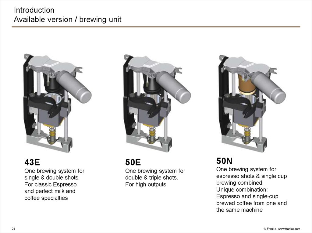
IntroductionAvailable version / brewing unit
21
43E
50E
50N
One brewing system for
single & double shots.
For classic Espresso
and perfect milk and
coffee specialties
One brewing system for
double & triple shots.
For high outputs
One brewing system for
espresso shots & single cup
brewing combined.
Unique combination:
Espresso and single-cup
brewed coffee from one and
the same machine
© Franke, www.franke.com
22. Technical construction Overview
Water connectionPump
Valves (Plastic)
Heating unit
Thermoblock
Cold water valve block
Flow meter with pressure block
Coffee boiler
Hotwater block
Brewing valve
Tea / steam boiler
Steam block
Hot water valve
Drainage valve
Brewing unit
Coffee outlet
Front door
Coverplate
Instant
Grinder / bean monotoring
Milk system FM (Foam Master)
Electronic overview
Power board 3.1
Vetro Touch
Digital input
Analog input
22
© Franke, www.franke.com
23. Technical construction Water connection
ElectricalWater flow
Y33
wt wt
filter
Main water valve
Filter
23
Pressure main water
80-800Pa
0.8 – 8 bar
© Franke, www.franke.com
24. Technical construction Pump
ElectricalWater flow
Cold water valve block
L=285mm
Capacitor 7uF
L= 370mm
Bypass
Adjustment of water
pressure
RV
bu
bn
M2
Bypass
Pressure main water
80-800Pa
0.8 – 8 bar
24
© Franke, www.franke.com
25. Technical construction 2/2- way plastic valve
a)1)
2)
3)
4)
5)
6)
7)
b)
8)
9)
10)
25
1)
2)
3)
4)
Coil
Bayonet lock
Plunger with ram (stainless steel)
Sealing diaphragm EPDM
(ethylene propylene diene monomer)
5) O-ring (ram seal)
6) Sealing surface
7) Guide clamp
8) Valve body seat
9) O-ring (seals on sealing surface 6)
10)Groove for clamp
These plastic valves are less susceptible to scaling and easier to
replace on account of their modular design. Due to the diaphragm, the
rear part of the plunger is not submerged (separate from medium).
There is no overseat or underseat and the valves can open on both
sides in case of excessive operating pressure. The valves were
specially designed for Franke Kaffeemaschinen AG.
Technical data:
Test pressure:
Operating pressure:
Valve body material:
Room temperature:
Medium temperature:
Voltage:
Power output:
12 bar
8 bar
Radel (polyphenylsulfone, PPSU)
up to 80°C
up to 140°C
24 V
11.8 W
© Franke, www.franke.com
26. Technical construction 3/2 way plastic valve
1)2)
3)
4)
5)
6)
7)
8)
9)
26
1)
2)
3)
4)
5)
6)
7)
8)
9)
Coil
Bayonet lock
Plunger with ram (plastic)
Internal part (positionable over 180°)
O-ring
AVS quick-release lock
Valve body seat
O-ring
Groove for clamp
These plastic valves are less susceptible to scaling and easier to
replace on account of their modular design. In this valve, too, the rear
part of the plunger is not submerged (separate from medium). The
valves were specially designed for Franke Kaffeemaschinen AG.
Technical data:
Test pressure:
Operating pressure:
Valve body material:
Room temperature:
Medium temperature:
Voltage:
Power output:
5 bar
4 bar
Radel (polyphenylsulfone, PPSU)
up to 80°C
up to 140°C
24 V
11.8 W
© Franke, www.franke.com
27. Technical construction Heating unit V3
56
1
3
4
3
2
7
8
a) Hydraulic connections
1 = Water (main input)
2 = Brewing valve
3 = Instant
4 = Drainage
5 = Milk
6 = Milk rinse
7 = Steam/milk/coffee bypass
8 = Hot water
b) Electrical connections
1 = Boiler/thermoblock heating
2 = NTC sensors, level sensor, flowmeter
3 = Valves
2
1
2 / X17
X16
X15
X14
3L N PE
X120.7
K3
L3
N
X120.4
K2
L2
K1
L1
X120.1
PE
3 / X14
27
© Franke, www.franke.com
28. Technical construction Heating unit V3
1)2)
3)
1)
Heating unit module V3
2)
Thermoblock (continuous flow
heater)
3)
Cold water block
4)
Brewing valve Y1
5)
Drainage valve Y39
6)
Hot water valve Y4
7)
Tea/steam boiler (0.9l)
8)
Coffee boiler (0.9l)
9)
Hot water block
4)
5)
6)
9)
7)
10)
11)
8)
10) Flowmeter with pressure gauge
11) Steam block
28
© Franke, www.franke.com
29. Technical construction Thermoblock
7)6)
1)
2)
3)
4)
5)
6)
7)
5)
4)
3)
2)
1)
Thermoblock module
Holding cone
Thermal fuse (safety fuse) 144°C
Temperature sensor
Thermoblock
Boiler clamp
Thermoblock insulation
Thermoblock 2 kW:
No standard thermoblock on the market meets the required performance
characteristics (temperature, speed and heating power). Therefore, we
developed our own thermoblock. The temperature is monitored by a
temperature sensor (fixed value at 68°C) and controlled by the software.
For reasons of safety, two thermal fuses are mounted on the
thermoblock, which are integrated in the phase and neutral line as a
safety switch-off mechanism.
Technical data:
Temperature sensor
Sensor element:
Measuring range:
Max. temperature
Tolerance:
glass NTC 10 kW
10°C to 150°C
-50°C to 250°C
+-0.2°K
Safety thermal fuse (must be replaced when activated)
Type:
D142
Cut-out temperature:
144°C
Resistive current load:
16.7A
Tmax*:
180°C
* Tmax = maximum permitted temperature after cut-out
29
© Franke, www.franke.com
30. Technical construction Thermoblock
Water flowK3
+24Vdc-X
GND
X17.1
b
X17.2
a
Power board
+24Vdc
N
230Vac
Electrical
bk
bu
vt
Temperature sensor
2000W
Thermoblock
Thermal Fuse
Gear pump
H3
30
vt
B3
© Franke, www.franke.com
31. Technical construction Cold water valve block
1)6)
2)
Y4’
Y30
Y5
7)
8)
5)
RV
3)
BK328597 control valve
(adjustable orifice)
Y5:
Function:
Cable:
Remark:
Tea / steam boiler supply
yellow
reduced opening 1.0 mm
Y30:
Function:
Cable:
Remark:
cold water rinsing line
white
opening 3.0 mm
Y4’:
Function:
Cable:
Remark:
cold water by-pass valve
green
reduced opening 1.0 mm
1) 3-fold valve block (Basis)
2) Manually adjustable restrictor for cold water
addition
3) To steam block Y-piece
4) To refrigeration unit
5) Valve Y22 sanitizing
6) To flowmeter
7) Pump input
8) Feeding HW/S boiler
4)
31
© Franke, www.franke.com
32. Technical construction Cold water valve block
Water flowElectrical
ye ye
X14.10
X14.21
gn gn
wt wt
Cold water rinsing
Cold water by-pass valve
Tea / steam boiler supply
Y5
32
X14.9
X14.20
X14.11
GND
X14.22
Power board
+24V DCs
Y4’
Y30
© Franke, www.franke.com
33. Technical construction Flow meter
Electrical+24Vdc-X
GND
5Vdc
4)
X14.2
3)
Water flow
+24Vdc
X14.1
X14.12
2)
Powerboard
1)
5)
6)
Flow meter
Flow meter:
1) From cold water block
2) To pressure gauge
3) Coffee boiler supply
4) Flow meter
5) Check valve
6) Pressure gauge
ye bn bk
B8
The flowmeter is also used in the Flair fixed water
connection. As it is made of plastic, it is less susceptible
to scaling and damage from acidic or alkaline water.
33
© Franke, www.franke.com
34. Technical construction Coffee boiler, 2.5kW (0.9l)
1)1)
2)
3)
4)
5)
6)
7)
Safety valve12 bar (Spectra)
NTC temperature sensor
Coffee boiler supply
Output hot water block
Output brewing valve
Electrical connection, heating element
Thermal fuse (safety fuse) 144°C
2)
1)
7)
6)
3)
4)
5)
The coffee boiler is the same as the tea / steam boiler. The design is
identical. The safety switch-off is achieved using two safety fuses. The
maximum pressure remains at 12 bar and the maximum operating
pressure remains at 8 bar.
34
© Franke, www.franke.com
35. Technical construction Coffee boiler 2.5kW
Water flow+24Vdc
a
K2
GND
X15.1
b
+24Vdc-X
X15.2
Power board
N
230Vac
Electrical
rd
bl
rd
rd
35
Temperature probe
2500W
Coffee boiler
Thermal Fuse
H1
B1
© Franke, www.franke.com
36. Technical construction Hot water valve block
Hot water valve block:Y22:
Function:
hot water rinsing line (sanitizing)
Cable:
pink
Remark:
opening 3.0 mm
1)
2)
3)
Y22
4)
Y25
5)
6)
Y3
Y25:
Function:
Cable:
Remark:
instant valve
red
reduced opening 1.0 mm
Y3:
Function:
Cable:
Remark:
bypass valve
gray
reduced opening 1.0 mm
1)
2)
3)
4)
5)
6)
Coffee boiler input
3-fold valve block (Basis)
To Y-piece from valve Y30
To instant mixer
To Y-piece in the front door
Restrictor 0.8 mm
Brewing valve Y1:
Function:
brewing valve
Cable:
orange
1) To brewing unit
2) From coffee boiler
3) Drainage of brewing unit (dribble box)
36
1)
2)
3)
© Franke, www.franke.com
37. Technical construction Hot water valve block
Water flowElectrical
Sanitizing
Instant valve
Y25
X14.3
X14.4
X14.15
X14.14
or
gy gy
rd
By-pass valve
rd
or
Brewing valve
vt
Y22
37
X13.4
X14.7
vt
X13.1
GND
X14.18
Power board
+24V DCs
Y3
Y1
© Franke, www.franke.com
38. Technical construction Tea / steam boiler, 2.5kW (0.9l/0.6l)
5)2)
1)
2)
3)
4)
5)
6)
7)
8)
NTC temperature sensor
Level sensor l=84 mm
Hot water valve output
Steam block output
Tea / steam boiler supply
Electrical connection, heating element
Pressure relief valve 3 bar (Pura)
Thermal fuse (safety fuse) 152°C
8)
1)
4)
3)
2)
6)
7)
7)
5)
1)
3)
The HW/S boiler is a modified version of the Pura standard boiler. The
safety fuses as those used for the thermoblock are used, which can be
replaced from the outside if they are activated. Due to the design
change with the thermoblock, the default temperature in the boiler is set
to 120°C instead of 130°C (old FM). Thus, only a 3-bar safety valve is
used.
38
© Franke, www.franke.com
39. Technical construction Tea / steam boiler, 2.5kW
Water flow+24Vdc
gy
X15.2
X15.1
b
X14.13
K2
GND
X14.11
a
+24Vdc-X
X14.22
Power board
N
230Vac
Electrical
bu
ye ye
gy
wt
gy
39
H2
Temperature probe
Level probe
Tea / steam boiler supply
2500W
Tea /steam boiler
Thermal Fuse
Y5
B5
B2
© Franke, www.franke.com
40. Technical construction Steam valve block
3)2)
1)
5)
4)
Y6
Y6:
Function:
Cable:
Marking:
Autosteam (3/2-way valve)
brown
white, opening 3.0 mm
Y20:
Function:
Cable:
Marking:
milk steam
violet
white, opening 2.0 mm
7)
Y20
RV
6)
1)
2)
3)
4)
5)
6)
7)
2-fold valve block (Basis)
Input from HW/S boiler
To front plug-in connection
Bleed (dribble box)
From drainage valve
Milk line to outlet Y-piece
To rinsing line
The Y20 is designed to heat the milk further after it has
already been heated by the thermoblock, without causing
it to caramelize. Products with a temperature of up to
80°C can be produced without spraying.
The Y6 is for the Autosteam option and is always
installed.
40
© Franke, www.franke.com
41. Technical construction Steam valve block
Water flowElectrical
bn bn
vt
vt
Milk steam
Autosteam
Y6
41
X14.6
X14.17
X14.8
GND
X14.19
Power board
+24V DCs
Y20
© Franke, www.franke.com
42. Technical construction Hot water valve
Y4:Function:
Cable:
Remark:
1)
2)
1)
2)
3)
4)
hot water/tea
blue
opening 3.0 mm
To front plug-in connection
1-fold valve block
From HW/S boiler
From cold water block (regulating valve)
3)
4)
42
© Franke, www.franke.com
43. Technical construction Steam valve block
Water flowElectrical
X14.5
GND
X14.16
Power board
+24V DCs
Hot water valve
wt wt
Y4
43
© Franke, www.franke.com
44. Technical construction Drainage valve
Y39:Function:
Cable:
drainage
green
1)
2)
3)
1) To outlet
2) From thermoblock
3) To bulkhead connection (drain)
The drainage valve has two functions:
• To ensure that residual water does not flow into the cup
when the first product is dispensed after rinsing.
• To ensure that when preparing an espresso macchiato,
the milk quantity dispensed into the cup is not too high.
44
© Franke, www.franke.com
45. Technical construction Steam valve block
Water flowElectrical
X26.8
GND
X26.16
Power board
+24V DCs
Drainage valve
gn gn
Y39
45
© Franke, www.franke.com
46. Technical construction Brewing Unit 43E / 50E / 50N
1) Light barrier2) DC-Motor
3) Encoder / Increment
50E
1)
2)
3)
43E
46
50N
© Franke, www.franke.com
47. Technical construction Brewing Unit
Water flowElectrical
N
BG
motor driver
Input
encoder
Power board
230Vac-X
coffee
rd
ye gn bn bu
bl
rd bu
bu
bl
Light barrier
DC-Motor
Brewing chamber heater
Encoder / Increment
rd
H6
47
© Franke, www.franke.com
48. Technical construction Fixed increment positions
1´576 Increments1´540 Increments
1´260 Increments
Brewing position
E 043 E 042
1´245 Increments
1´240 Increments
730 Increments
Upper limit
E120 No ground coffee
Pressure and Time = 0
Min. required position during brewing
Brewing chamber closed
Grinding position
E 041
610 Increments
Powder chute position
E 044
250 Increments
Cleaning position
118 Increments Re-calibration point (light barrier)
110 Increments Reversal point
100 Increments
Lower limit/Re-calibration point (current rise)
48
© Franke, www.franke.com
49. Technical construction Coffee outlet
Coffee outlet:1) Outlet supporter top
2) Distributor FM
3) Frother
4) Outlet bottom part cpl.
black
Distributor FM:
1) Cold or hot milk
2) Coffee
1)
1)
2)
2)
Option
Distributor FM FS:
3) Syrup tubes
3)
3)
4)
49
© Franke, www.franke.com
50. Technical construction Front door
Electrical+24Vdc
1) Outlet DC-Motor 24VDC
2) Reed switch
3) Gear wheel to the outlet
+24Vdc-X
GND
gy
bu rd
1)
3)
50
Reed switch
gy
Outlet DC-Motor
2)
Outlet
Motor
© Franke, www.franke.com
51. Technical construction Front door
1)2)
3)
4)
7)
Front door:
1) Brewing unit
2) Bypass
3) Cold milk
4) Hot milk
5) Autosteam (outlet on right)
6) Hot water dispenser (outlet on left)
7) Only in machines without Autosteam
8) Instant outlet
9) Valve outlet switch
Valve outlet switch:
1) To the jug outlet
2) From the brewing unit
3) To the coffee outlet
5)
9)
6)
8)
6)
Outlet for jug
51
Autosteam
© Franke, www.franke.com
52. Technical construction Brewing Unit
milkinstant
Power board
coffee
Water flow
Electrical
+24V DCs
GND
Valve outlet switch
bn bn
52
outlet
cup
© Franke, www.franke.com
53. Technical construction Coverplate
1)2)
Powder dosing unit
3)
4)
5)
Double powder dosing unit
1)
2)
3)
4)
5)
53
Coverplate
Blind lid
Support grinder outside
Support grinder center
Cover cpl. / Cover cpl. locked
© Franke, www.franke.com
54. Technical construction Instant
5)1)
2)
3)
4)
5)
6)
7)
8)
Mixing chamber
Whipper motor
Suction cover
6)
Instant fan
Light barrier for powder dosing unit
Instant motor for powder dosing unit
Light barrier for double powder dosing unit
Instant motor for double powder dosing unit
Y25
Hot water
7)
8)
4)
3)
1)
2)
54
© Franke, www.franke.com
55. Technical construction Instant
Water flowElectrical
+24Vdc
Power board
+24Vdc-X
GND
wt
wt
bl
gn
bl
rd
rd rd
bl rd
55
Instant left
Instant right
Quirler motor
Valve hot water instant
Instant fan
outlet
cup
© Franke, www.franke.com
56. Technical construction Grinder / bean monitoring
Phototransistorrd
56
Grinder right
Grinder specification:
• 230V 50/60Hz
• Capacitor 14uF
• Isolation class «F»
• Output min. 3gr. / sec.
• UL approved
bl
rd
bl
rd
bl
Grinder left
Light barrier
IR-LED
Grinder center
ceramic
burrs
Power board
Electrical
© Franke, www.franke.com
57. Technical construction Milk system FM (Foam Master)
1 Coffee machine, 1 milk2 Coffee machine, 1 milk
Milk slide in module
57
© Franke, www.franke.com
58.
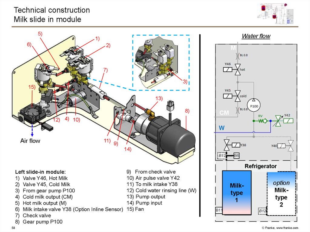
Technical constructionMilk slide in module
5)
Water flow
1)
6)
2)
M
7)
3)
15)
13)
8)
CM
12) 4) 10)
W
Air flow
11)
9)
14)
Refrigerator
Left slide-in module:
1) Valve Y46, Hot Milk
2) Valve Y45, Cold Milk
3) From gear pump P100
4) Cold milk output (CM)
5) Hot milk output (M)
6) Milk intake valve Y38 (Option Inline Sensor)
7) Check valve
8) Gear pump P100
58
9) From check valve
10) Air pulse valve Y42
11) To milk intake Y38
12) Cold water rinsing line (W)
13) Pump output
14) Pump input
15) Fan
Milktype
1
option
Milktype
2
© Franke, www.franke.com
59. Technical construction Foam Master PCB
NTCLevel 1
R
Level 2
C
Technical construction
Foam Master PCB
CAN ID 70 CAN ID 71 CAN ID 72 CAN ID 73
3 OFF
4 OFF
ON 3 OFF
3
3
ON 4
4 OFF
4
ON
Item
Meaning
P1
Gear pump
ON
Earth connection
USB
CAN
Fuse
Y42
Air valve
Y45
Change valve hot&cold
Y38
Milk selection valve
Fan
Pump plate fan (front/rear)
24VDC
Fuse
Fuse FST 5x20 3.15 A
CAN
CAN-bus connections
USB
USB connection for software
updates with Service Tool 3
CAN-ID
CAN-ID configuration via DIP
switches 3 and 4
24 VDC
Y40
Fan
Y46
Y45
Y38
Y42
P1
NTC
59
Power connection
Milk temperature sensor
connection
Level 1
Milk detection (conductive sensor)
Level 2
Milk level (capacitive sensor)
© Franke, www.franke.com
60. Technical construction Gear pump
Construction and functionalityDrive motor with tachometer
Electrical
connection
Magnetic coupling
Pump head
Intake connection
U Power supply
24V
Tachometer signal
5V
Speed (0-5V)
0V
I
60
t
P
I
P
I
The gear pump is a rotary pump consisting of
two toothed gears rotating in opposite directions,
which engage on the intake side of the pump.
Both an intake connection (I) and a pressure line
connection (P) are located on the pump head.
The drive gear is linked to the drive motor via the
magnetic coupling and drives the other toothed
gear. Milk is drawn into the open space between
the shoulders of the gears and the housing and
transported to the pressure side. After the milk
reaches the pressure side, the teeth on both
gears fill the open spaces. This results in the
pulsation-free conveying of the milk. The pump
motor electronics are supplied with 24 VDC.
Speed of revolution is set by using a DC voltage
signal of 0 - 5 VDC. The tachometer sends a total
of 4 impulses to the Foam Master controls with
each revolution. The flow rate is 1000 ml/min and
the output pressure is 4 bar.
P
© Franke, www.franke.com
61. Technical construction Air valve
Electricalconnection
Y42
1
2
1
on
61
Construction and functionality
The valve plate (sealing element) is directly linked
to the armature. In the power-off state, spring
tension causes it to press against the valve
seating, which closes off the path between
Coil
connection 1 and connection 2.
Armature
Applying a voltage to the coil creates a magnetic
Spring
field, which pulls the armature upward, opening
Valve plate
the path between connection 1 and connection 2.
Valve seating In the application in the Foam Master, the air valve
is controlled by the Foam Master PCB with a
PWM (pulse width modulation) signal
2
with a frequency of 10 Hz.
The higher the air percentage value set in the
product configuration,
- The longer the duration of the pulse (t_on)
relative to the pulse interval (t_off).
off
- the longer the average time the valve is open.
- The larger the quantity of air added.
- The dense the milk foam.
© Franke, www.franke.com
62. Technical construction Overview electronic
Can-Bus connectorPower board (PCB) 3.1
Transformer (USA, Version)
Line Filter
Switch-mode power supply
62
© Franke, www.franke.com
63. Technical construction Power board (PCB) 3.1
X37X20
X19
X2
X18R
D
X3
X24
X21
X1
X18L
X4
X26
X5
X8
X7
X6
X9
X35
C
X36
K1
X34
X17
X39
K2
JP3
X16 X15
X22
X11
X14
63
X31
K3
X10
X18
X13
X38
X27
X32 X29
K1/2/3
X8
X7
X6
X5
X4
X3/2/1
X20/19/18L/R
X27
X29
X32
X18
X18
X37
X22
JP3
X11
X31
X39
X35/36
X34
X9
X38
X10
X24
X21
X15
X16
X17
X26
X13
X14
C
D
Heater coffee/tea_steam1/tea_steam2
Connection neutral line
Connection 208 Vac
Connection 230 Vac
Heater Brewing unit
Water pump
Grinder right/middle/left
Monitoring grinder:right/middle/left(Instant:left/right)
24 Vdc X
24 dc constant
GND
Fuse F2 very slow blow 4A (brewing unit)
Fuse F1 very slow blow 4A (logic, valves)
Brewing unit 24Vdc
CAN-Bus internal (Power print)
Jumper CAN-End
Comm. Module CCI/CSI
Comm. Module FW
Milk option
Ventilator 1&2
Instant option
Transformer primary
Transformer secondary 24Vac
Power from the switching power supply
Communication CPU
Supply front panel 24Vdc
NTC tea/steam boiler
NTC coffee boiler
NTC Thermoblock
Input/output
Options boiler module
Connection boiler module
Processor FUJI
Motor driver brew unit
© Franke, www.franke.com
64. Technical construction Switch-mode power supply
Power Milk Print24VDC
Powerboard 3.1 /
24VDC
64
Power 176-265VAC
Fuse external
© Franke, www.franke.com
65. Technical construction Operator panel / Vetro Touch
1)2)
3)
4)
5)
6)
7)
8)
9)
1)
2)
Panel holder guide
Panel connection
Panel
Edge illumination
CPU operator panel
Touch / Plexiglass
Panel sealing
USB-Stick protection
Screw cover
9)
3)
4)
5)
6)
When changing the panel, it is essential that the
machine is de-energized first.
7)
8)
65
© Franke, www.franke.com
66. Technical construction Flavour Station (Option)
5Technical construction
Flavour Station (Option)
2)
1) Electrical part
2) Peristaltic pump
3) Drawer
3)
1)
66
© Franke, www.franke.com
67. Technical construction Flavour Station / electrical part
LEDOutput
Mains connection
Function
The switching power supply is supplied with mains voltage via
the flavour station power switch and delivers 24 VDC to the
flavour station PCB.
In contrast to the power supply on the Foam Master system
power supply is completely separate from that of the coffee
machine. This requires that the flavour station always be
switched on, during operation as well as cleaning.
Technical data
Input voltage range: 85 - 264 VAC / 120 - 375 VDC
Output voltage: 24 VDC
Max. output current: 3.2 A
The output is short-circuit proofed.
When the switching power supply is receiving mains voltage, the
green LED lights up.
67
© Franke, www.franke.com
68. Technical construction Flavour Station / electrical part
P1P2
P3
Switch Settings for FM850
(underline)
Fuse
ON
24 VDC
Priming
button
CAN USB
68
OFF
54
6
0
0
0
0
0
1
CAN Bus
Pumps
Chocco
Chocco
Chocco
Chocco
Pump return
Pump return
53
3
1
1
1
1
1
0
0
1
0
0
0
0
0
0
Revolution
Revolution
1
0
1
1
1
1
1
1
© Franke, www.franke.com
69. Technical construction Flavour Station / mechanical part
Stepper motorCoupling
Supporter of the motor
Peristaltic pump
Cover
69
© Franke, www.franke.com
70. Technical construction Flavour Station / Function of the pump
70© Franke, www.franke.com
71. Operating
Switch over to the Maintenance level by tipping on the Franke logo in the upperleft-hand corner of the monitor and then entering the PIN code.
Select the Service Menu. The PIN code for the maintenance level is comprised of:
(Day + Month) * Year * (Hour + Minute).
Use the date and time information on the operator panel (upper right corner).
Example: 28.09.2012; 11:36
PIN code: 37*2012*47
If a user is currently still logged on, tip twice on the Franke logo.
You can then authenticate yourself with a new user right.
71
© Franke, www.franke.com
72. Operating Operator panel construction
FM85072
© Franke, www.franke.com
73. Operating Input methods
73© Franke, www.franke.com
74. Programming Service Menu
74© Franke, www.franke.com
75. Programming Commissioning
FM85075
© Franke, www.franke.com
76. Programming Configure machine
FM85076
© Franke, www.franke.com
77. Programming Set Drinks
77© Franke, www.franke.com
78. Programming Date and Time
78© Franke, www.franke.com
79. Programming Test functions
79© Franke, www.franke.com
80. Programming Access rights
80© Franke, www.franke.com
81. Programming Decommissioning
81© Franke, www.franke.com
82. Programming Updating the software
82© Franke, www.franke.com
83. Programming Individualization and data transfer
83© Franke, www.franke.com
84. Programming Modify depiction
84© Franke, www.franke.com
85. Programming Backing up/loading
All setting in the menu«0 Commmissioning» is NOT included in
the confugration back up.
85
© Franke, www.franke.com
86. Programming Counters
86© Franke, www.franke.com
87. Water flow circuit diagram
Coffee boilerInstant
system
Thermoblock
Back
Outlet
switch
Tea / steam boiler
Gear
pump
Refrigerator
Tea
87
Coffee
Cappu
Milk
sorte
1
option
Milk
sorte
2
© Franke, www.franke.com
88. FM850
− Commissioning− Product adjustment
− Troubleshooting
− Cleaning
88
© Franke, www.franke.com
89.
THANK YOU FOR YOURATTENTION
89
© Franke, www.franke.com