


 electronics
Similar presentations:


")
Control System of Wall-split Inverter
1.
Control System of Wall-split InverteTechnical Support Department
October 22
2.
Inverter Indoor PCBContents
Create a beautifulPrinciple of Inverter Control
life for human
beings
Inverter Outdoor PCB
Main Components
Troubleshooting
3.
Inverter Indoor PCB4.
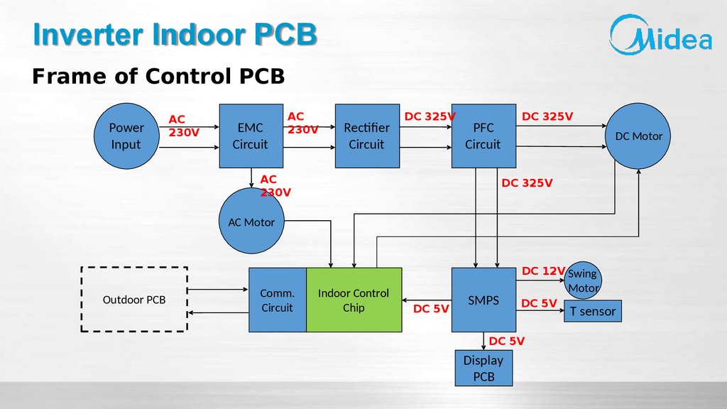
Inverter Indoor PCBFrame of Control PCB
Power
Input
AC
230V
EMC
Circuit
AC
230V
Rectifier
Circuit
DC 325V
DC 325V
PFC
Circuit
AC
230V
DC Motor
DC 325V
AC Motor
DC 12V Swing
Outdoor PCB
Comm.
Circuit
Indoor Control
Chip
DC 5V
SMPS
Motor
DC 5V
DC 5V
Display
PCB
T sensor
5.
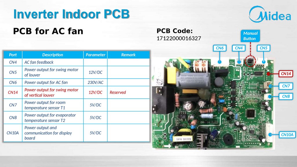
Inverter Indoor PCBPCB for AC fan
PCB Code:
17122000016327
Manual
Button
CN6
Port
Description
Parameter
CN4
AC fan feedback
CN5
Power output for swing motor
of louver
12V/DC
CN6
Power output for AC fan
230V/AC
CN14
Power output for swing motor
of vertical louver
12V/DC
CN7
Power output for room
temperature sensor T1
5V/DC
CN8
Power output for evaporator
temperature sensor T2
5V/DC
CN10A
Power output and
communication for display
board
5V/DC
CN4
CN5
Remark
CN14
CN7
Reserved
CN8
CN10A
6.
Inverter Indoor PCBPCB for DC fan
PCB Code:
17122000036612
Manual
Button
CN3
Port
Description
Parameter
CN3
Power output for DC Fan
CN8
Power output for swing motor
of louver
12V/DC
CN20
Power output for swing motor
of vertical louver
12V/DC
CN7
Power output for room
temperature sensor T1
5V/DC
CN6
Power output for evaporator
temperature sensor T2
5V/DC
CN10A
Power output and
communication for display
board
5V/DC
CN225
Power output for ionizer or
plasma
230V/AC
CN51
Port for 12V output
12V/DC
CN8
Remark
CN20
Reserved
CN7
CN6
CN10A
Reserved
CN51
CN225
7.
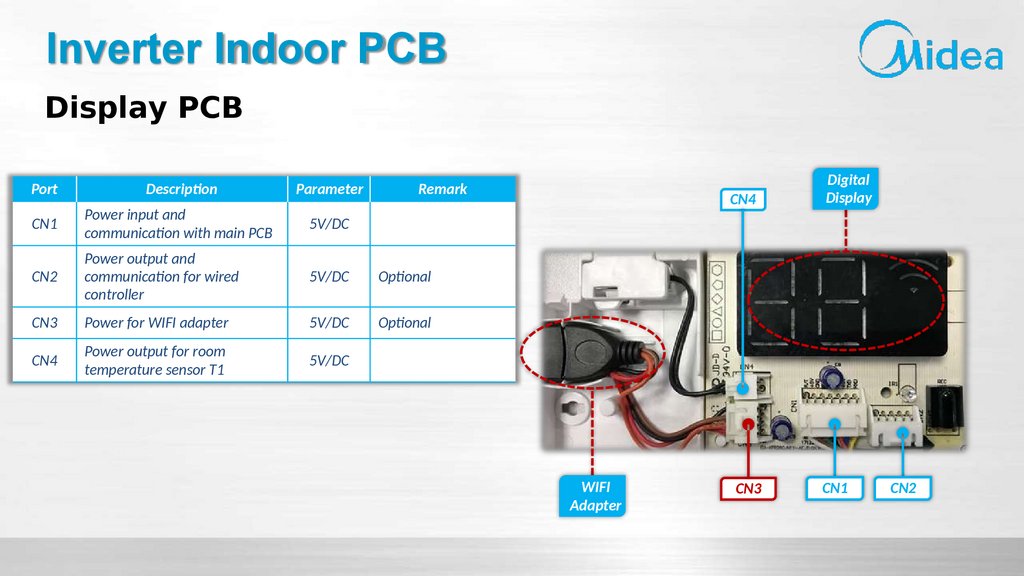
Inverter Indoor PCBDisplay PCB
Port
Description
Parameter
Remark
CN1
Power input and
communication with main PCB
5V/DC
CN2
Power output and
communication for wired
controller
5V/DC
Optional
CN3
Power for WIFI adapter
5V/DC
Optional
CN4
Power output for room
temperature sensor T1
5V/DC
WIFI
Adapter
CN4
Digital
Display
CN3
CN1
CN2
8.
Principle of Inverter Control9.
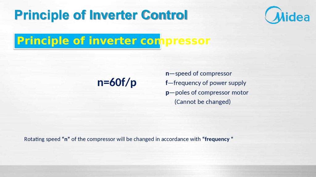
Principle of Inverter ControlPrinciple of inverter compressor
n=60f/p
n—speed of compressor
f—frequency of power supply
p—poles of compressor motor
(Cannot be changed)
Rotating speed “n” of the compressor will be changed in accordance with “frequency “
10.
Principle of Inverter ControlIn air conditioning systems, inverters are largely referred to as devices which convert commercial AC
electricity to AC with adjustable frequency and voltage. Converter which converts AC to DC forms part of such
devices. The rotational speed of compressor can be altered freely by inverter.
Commercial AC
Electricity
October 22
Variable Frequency
Variable Voltage
Stabilized DC Voltage
AC
DC
CONVERSION
DC
AC
CONVERSION
CONVERTER
INVERTER
COMPR
ESSOR
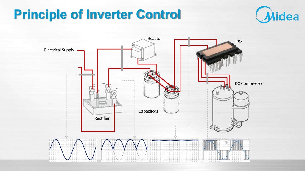
11.
Principle of Inverter ControlReactor
IPM
Electrical Supply
DC Compressor
Capacitors
Rectifier
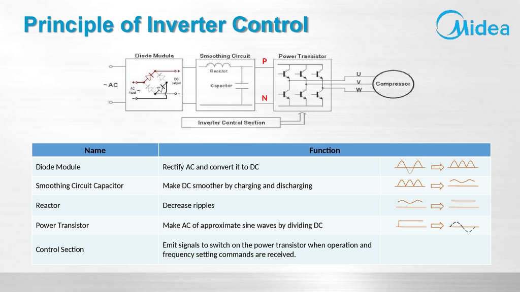
12.
Principle of Inverter ControlP
N
Name
Function
Diode Module
Rectify AC and convert it to DC
Smoothing Circuit Capacitor
Make DC smoother by charging and discharging
Reactor
Decrease ripples
Power Transistor
Make AC of approximate sine waves by dividing DC
Control Section
Emit signals to switch on the power transistor when operation and
frequency setting commands are received.
13.
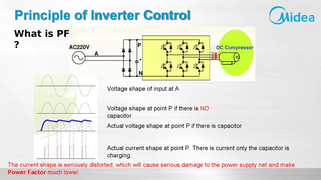
Principle of Inverter ControlWhat is PFC
?
Voltage shape of input at A
Voltage shape at point P if there is NO
capacitor
Actual voltage shape at point P if there is capacitor
Actual current shape at point P. There is current only the capacitor is
charging.
The current shape is seriously distorted, which will cause serious damage to the power supply net and make
Power Factor much lower.
14.
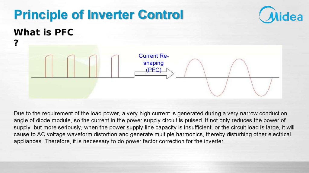
Principle of Inverter ControlWhat is PFC
?
Current Reshaping
(PFC)
Due to the requirement of the load power, a very high current is generated during a very narrow conduction
angle of diode module, so the current in the power supply circuit is pulsed. It not only reduces the power of
supply, but more seriously, when the power supply line capacity is insufficient, or the circuit load is large, it will
cause to AC voltage waveform distortion and generate multiple harmonics, thereby disturbing other electrical
appliances. Therefore, it is necessary to do power factor correction for the inverter.
15.
Principle of Inverter ControlPassive PFC
Voltage
Current
Passive PFC with PF=88%
An inductance (or reactor) is added between the rectifier and the filter capacitor, and the characteristic that the
current on the inductor cannot be abruptly is used to smooth the fluctuation of the capacitor charging strong
pulse and improve the distortion of the current waveform of the power supply.
Shortage: The reactor is in big size with high heat creation when it is work. Also it will pull down the DC voltage
and drag a higher current when the compressor is running.
16.
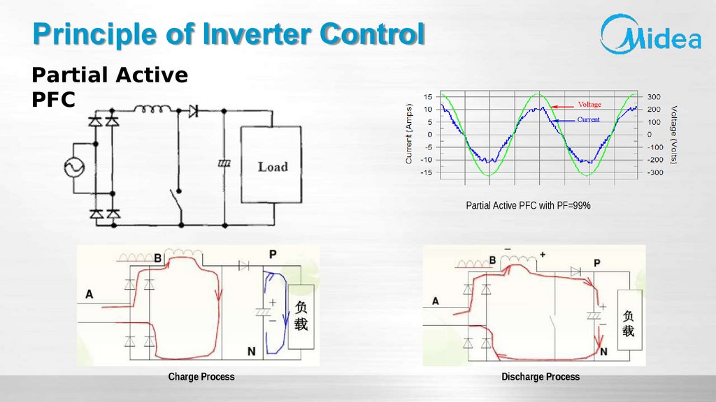
Principle of Inverter ControlPartial Active
PFC
Voltage
Current
Partial Active PFC with PF=99%
Charge Process
Discharge Process
17.
Inverter Outdoor PCB18.
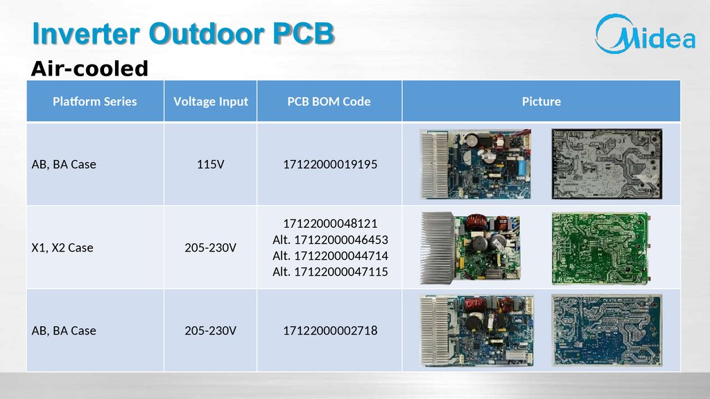
Inverter Outdoor PCBAir-cooled
Platform Series
Voltage Input
PCB BOM Code
115V
17122000019195
X1, X2 Case
205-230V
17122000048121
Alt. 17122000046453
Alt. 17122000044714
Alt. 17122000047115
AB, BA Case
205-230V
17122000002718
AB, BA Case
Picture
19.
Inverter Outdoor PCBAir-cooled
Platform Series
CA Case
D Case
Voltage Input
PCB BOM Code
205-230V
17122000036588
205-230V
17122000002671 Main
17122000048172 Main
17122000008629 IPM
Picture
20.
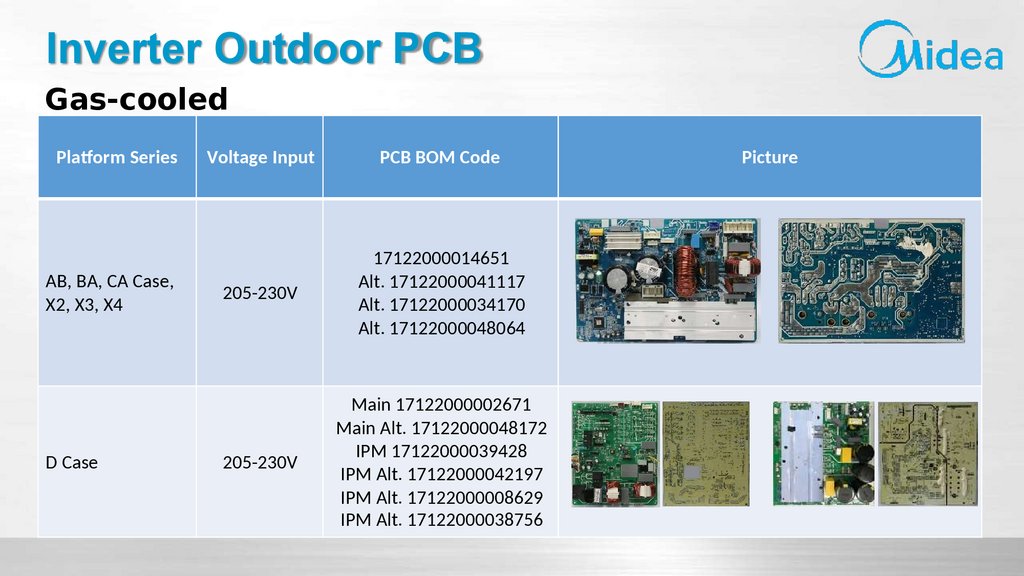
Inverter Outdoor PCBGas-cooled
Platform Series
AB, BA, CA Case,
X2, X3, X4
D Case
Voltage Input
PCB BOM Code
205-230V
17122000014651
Alt. 17122000041117
Alt. 17122000034170
Alt. 17122000048064
205-230V
Main 17122000002671
Main Alt. 17122000048172
IPM 17122000039428
IPM Alt. 17122000042197
IPM Alt. 17122000008629
IPM Alt. 17122000038756
Picture
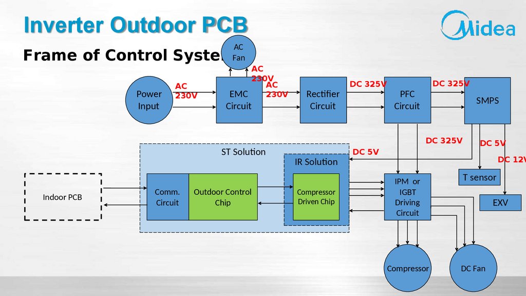
21.
Inverter Outdoor PCBAC
Fan
Frame of Control System
Power
Input
AC
230V
AC
230V
AC
230V
EMC
Circuit
ST Solution
Indoor PCB
Comm.
Circuit
Outdoor Control
Chip
Rectifier
Circuit
DC 325V
DC 325V
PFC
Circuit
SMPS
DC 325V
IR Solution
Compressor
Driven Chip
DC 5V
DC 5V
DC 12V
IPM or
IGBT
Driving
Circuit
Compressor
T sensor
EXV
DC Fan
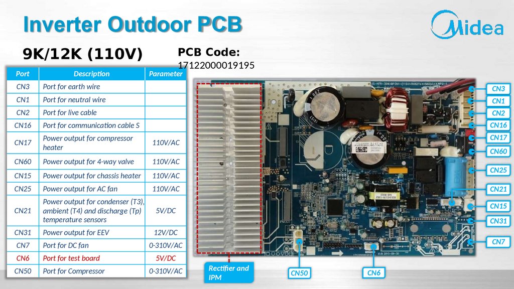
22.
Inverter Outdoor PCB9K/12K (110V)
Port
Description
PCB Code:
17122000019195
Parameter
CN3
Port for earth wire
CN3
CN1
Port for neutral wire
CN1
CN2
Port for live cable
CN2
CN16
Port for communication cable S
CN16
CN17
Power output for compressor
heater
110V/AC
CN60
Power output for 4-way valve
110V/AC
CN15
Power output for chassis heater
110V/AC
CN25
Power output for AC fan
110V/AC
CN21
Power output for condenser (T3),
ambient (T4) and discharge (Tp)
temperature sensors
5V/DC
CN31
Power output for EEV
12V/DC
CN7
Port for DC fan
0-310V/AC
CN6
Port for test board
5V/DC
CN50
Port for Compressor
0-310V/AC
CN17
CN60
CN25
CN21
CN15
CN31
CN7
Rectifier and
IPM
CN50
CN6
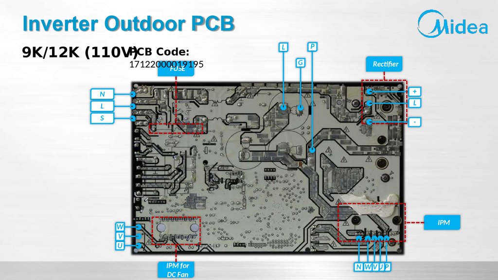
23.
Inverter Outdoor PCBPCB Code:
9K/12K (110V)
17122000019195
FUSE
P
L
G
Rectifier
+
N
L
L
S
-
IPM
W
V
U
IPM for
DC Fan
N W VU P
24.
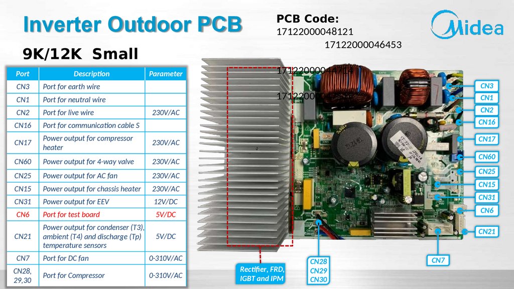
Inverter Outdoor PCB9K/12K Small
Port
Description
Parameter
CN3
Port for earth wire
CN1
Port for neutral wire
CN2
Port for live wire
CN16
Port for communication cable S
CN17
Power output for compressor
heater
230V/AC
CN60
Power output for 4-way valve
230V/AC
CN25
Power output for AC fan
230V/AC
CN15
Power output for chassis heater
230V/AC
CN31
Power output for EEV
12V/DC
CN6
Port for test board
5V/DC
CN21
Power output for condenser (T3),
ambient (T4) and discharge (Tp)
temperature sensors
5V/DC
CN7
Port for DC fan
0-310V/AC
CN28,
29,30
Port for Compressor
0-310V/AC
PCB Code:
17122000048121
17122000046453
17122000044714
CN3
17122000047115
CN1
CN2
230V/AC
CN16
CN17
CN60
CN25
CN15
CN31
CN6
CN21
Rectifier, FRD,
IGBT and IPM
CN28
CN29
CN30
CN7
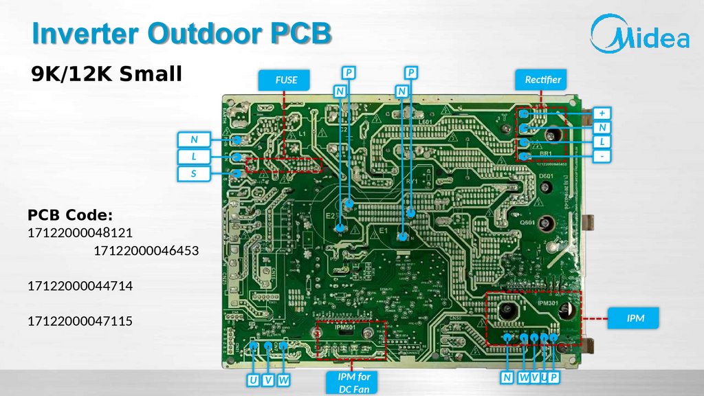
25.
Inverter Outdoor PCB9K/12K Small
FUSE
P
N
P
N
Rectifier
+
N
L
-
N
L
S
PCB Code:
17122000048121
17122000046453
17122000044714
17122000047115
IPM
U V W
IPM for
DC Fan
N WV UP
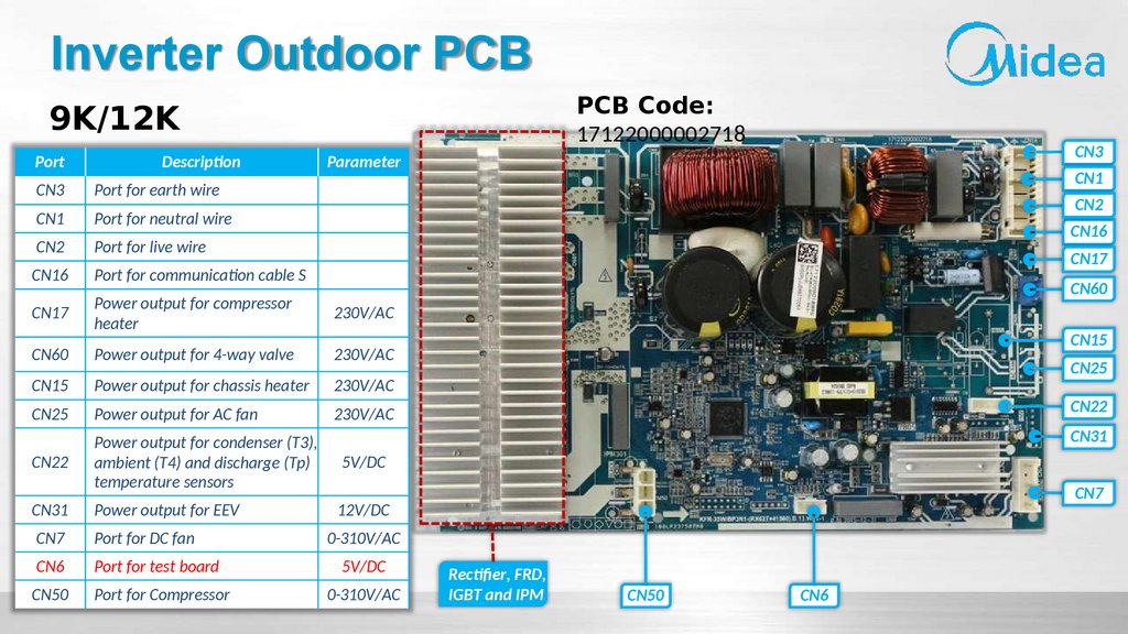
26.
Inverter Outdoor PCBPCB Code:
17122000002718
9K/12K
Port
Description
CN3
Parameter
CN3
Port for earth wire
CN1
Port for neutral wire
CN2
Port for live wire
CN16
Port for communication cable S
CN17
Power output for compressor
heater
230V/AC
CN60
Power output for 4-way valve
230V/AC
CN15
Power output for chassis heater
230V/AC
CN25
Power output for AC fan
230V/AC
CN22
Power output for condenser (T3),
ambient (T4) and discharge (Tp)
temperature sensors
5V/DC
CN31
Power output for EEV
12V/DC
CN7
Port for DC fan
0-310V/AC
CN6
Port for test board
5V/DC
CN50
Port for Compressor
0-310V/AC
CN1
CN2
CN16
CN17
CN60
CN15
CN25
CN22
CN31
CN7
Rectifier, FRD,
IGBT and IPM
CN50
CN6
27.
Inverter Outdoor PCB9K/12K
FUSE
P
N
PCB Code:
P
17122000002718
N
Rectifier
+
N
L
-
N
L
S
IPM
W
V
U
IPM for
DC Fan
N WV UP
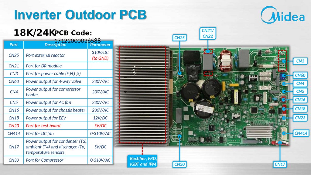
28.
Inverter Outdoor PCB18K/24KPCB Code:
CN25
17122000036588
CN21/
CN22
Port
Description
Parameter
CN25
Port external reactor
310V/DC
(to GND)
CN21
Port for DR module
CN3
Port for power cable (E,N,L,S)
CN60
Power output for 4-way valve
230V/AC
CN4
Power output for compressor
heater
CN4
230V/AC
CN5
CN5
Power output for AC fan
230V/AC
CN16
Power output for chassis heater
230V/AC
CN18
CN18
Power output for EEV
12V/DC
CN23
CN23
Port for test board
5V/DC
CN414
Port for DC fan
CN17
Power output for condenser (T3),
ambient (T4) and discharge (Tp)
temperature sensors
CN30
Port for Compressor
CN3
CN60
CN16
CN414
0-310V/AC
5V/DC
0-310V/AC
Rectifier, FRD,
IGBT and IPM
CN30
CN17
29.
Inverter Outdoor PCB18K/24K
FUSE
PCB Code:
17122000036588 P
N
P
Rectifier
N
N
L
+
N
L
S
N
W
V
U
P
U
V
W
IPM for
DC Fan
IPM
30.
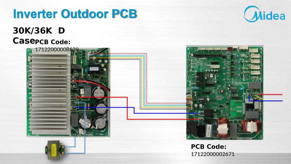
Inverter Outdoor PCB30K/36K D
CasePCB Code:
17122000008629
PCB Code:
17122000002671
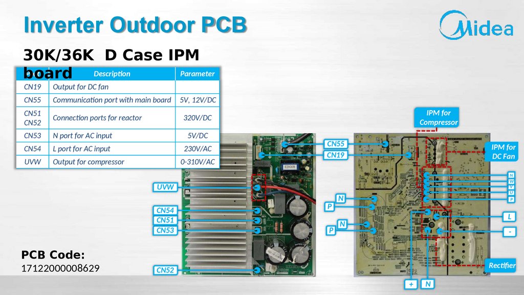
31.
Inverter Outdoor PCB30K/36K D Case IPM
Port
Description
Parameter
board
CN19
Output for DC fan
CN55
Communication port with main board
5V, 12V/DC
CN51
CN52
Connection ports for reactor
320V/DC
CN53
N port for AC input
5V/DC
CN54
L port for AC input
230V/AC
UVW
Output for compressor
0-310V/AC
IPM for
Compressor
CN55
CN19
IPM for
DC Fan
N
W
V
U
UVW
CN54
CN51
CN53
PCB Code:
17122000008629
P
P
N
P
L
N
-
Rectifier
CN52
+
N
32.
Inverter Outdoor PCBPCB Code:
17122000002671
30K/36K D Case main
Port
Description
Parameter
board
CN14
CN34
17122000048172
CN33
CN20
CN1
Port for L-in
CN2
Port for N-in
CN6
L-out for IPM board
CN5
N-out for IPM board
CN7
Port for communication with IPM board
CN9
Port for Hi-pressure and low-pressure switches
CN8
Power output for condenser (T3), ambient (T4)
temperature sensors
5V/DC
CN44
Power output for compressor heater
230V/AC
CN40
Power output for chassis heater
230V/AC
CN8
CN22
Power output for 4-way valve
230V/AC
CN9
CN33
Power output for discharge (T5) temperature sensor
5V/DC
CN7
CN14
Port for compressor top high temperature protector
CN20
Power output for EEV
CN34
Port for communication with indoor unit
CN6
Port for test board
CN12
Output for DC fan
CN11
Input for DC Fan
CN6
230V/AC
230V/AC
5V/DC
12V/DC
5V/DC
Main Chip
CN40
CN22
EEPROM
CN44
CN5
CN6
CN1
CN2
Digital
Display
Check
Button
33.
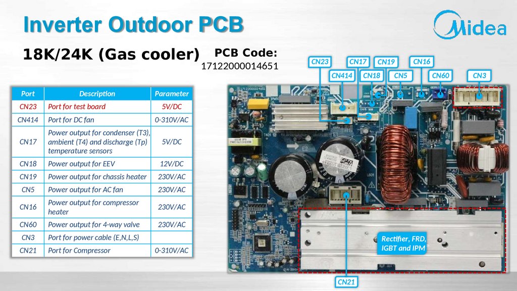
Inverter Outdoor PCB18K/24K (Gas cooler)
Port
Description
PCB Code:
17122000014651
CN23
CN17
CN414
CN19
CN18
CN16
CN5
Parameter
CN23
Port for test board
5V/DC
CN414
Port for DC fan
CN17
Power output for condenser (T3),
ambient (T4) and discharge (Tp)
temperature sensors
5V/DC
CN18
Power output for EEV
12V/DC
CN19
Power output for chassis heater
230V/AC
CN5
Power output for AC fan
230V/AC
CN16
Power output for compressor
heater
230V/AC
CN60
Power output for 4-way valve
230V/AC
CN3
Port for power cable (E,N,L,S)
CN21
Port for Compressor
0-310V/AC
Rectifier, FRD,
IGBT and IPM
0-310V/AC
CN21
CN60
CN3
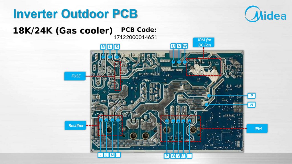
34.
Inverter Outdoor PCB18K/24K (Gas cooler)
N
L
PCB Code:
17122000014651
S
U V W
IPM for
DC Fan
FUSE
P
N
Rectifier
IPM
- L N+
P W VUN
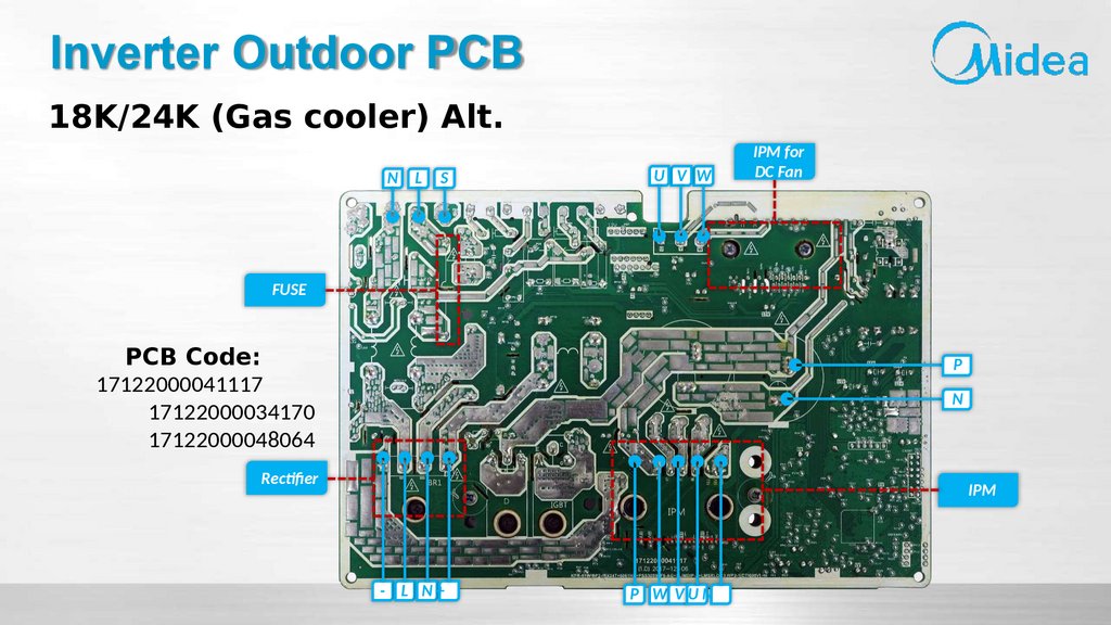
35.
Inverter Outdoor PCBPCB Code:
18K/24K (Gas cooler) Alt.
Port
Description
Parameter
CN23
Port for test board
CN414
Port for DC fan
CN17
Power output for condenser (T3),
ambient (T4) and discharge (Tp)
temperature sensors
5V/DC
CN18
Power output for EEV
12V/DC
CN19
Power output for chassis heater
230V/AC
CN5
Power output for AC fan
230V/AC
CN16
Power output for compressor
heater
230V/AC
CN60
Power output for 4-way valve
230V/AC
CN3
Port for power cable (E,N,L,S)
CN27
Port for Compressor
CN23
CN17 CN19
CN16
17122000041117
CN414 CN18
CN60
CN5
17122000034170
17122000048064
5V/DC
0-310V/AC
Rectifier, FRD,
IGBT and IPM
0-310V/AC
CN27
CN3
36.
Inverter Outdoor PCB18K/24K (Gas cooler) Alt.
N
L
S
U V W
IPM for
DC Fan
FUSE
PCB Code:
17122000041117
17122000034170
17122000048064
P
N
Rectifier
IPM
- L N+
P W VUN
37.
Inverter Outdoor PCB30K/36K (Gas
cooler)
PCB Code:
17122000008629
17122000039428
17122000042197
17122000038756
L
N
PCB Code:
17122000002671
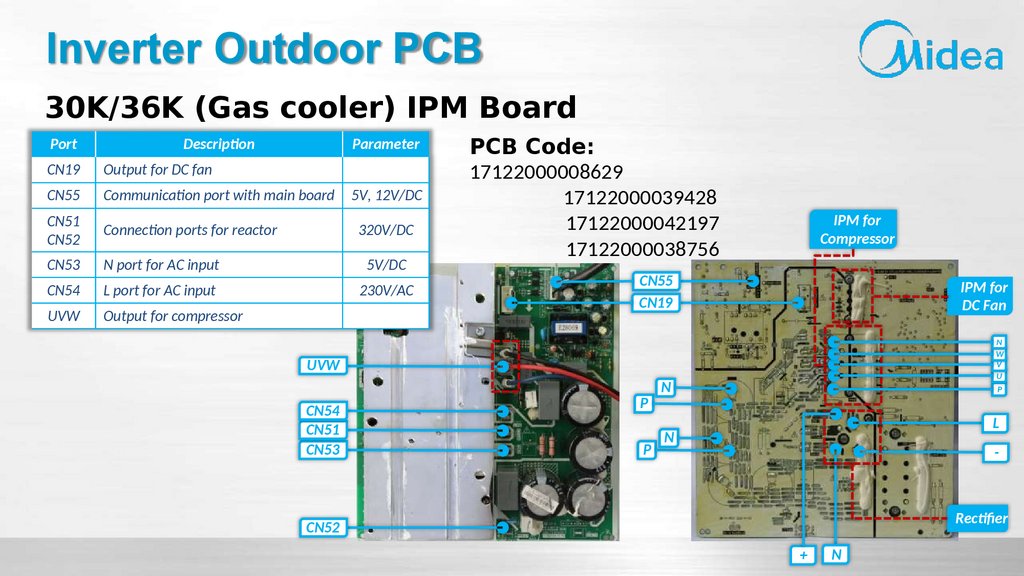
38.
Inverter Outdoor PCB30K/36K (Gas cooler) IPM Board
Port
Description
Parameter
CN19
Output for DC fan
CN55
Communication port with main board
5V, 12V/DC
CN51
CN52
Connection ports for reactor
320V/DC
CN53
N port for AC input
5V/DC
CN54
L port for AC input
230V/AC
UVW
Output for compressor
PCB Code:
17122000008629
17122000039428
17122000042197
17122000038756
IPM for
Compressor
CN55
CN19
IPM for
DC Fan
N
W
V
U
UVW
CN54
CN51
CN53
P
P
N
P
L
N
-
Rectifier
CN52
+
N
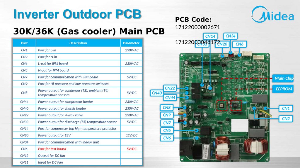
39.
Inverter Outdoor PCBPCB Code:
17122000002671
30K/36K (Gas cooler) Main PCB
Port
Description
CN14
CN34
17122000048172
CN33
CN20
Parameter
CN1
Port for L-in
CN2
Port for N-in
CN6
L-out for IPM board
CN5
N-out for IPM board
CN7
Port for communication with IPM board
CN9
Port for Hi-pressure and low-pressure switches
CN8
Power output for condenser (T3), ambient (T4)
temperature sensors
5V/DC
CN44
Power output for compressor heater
230V/AC
CN40
Power output for chassis heater
230V/AC
CN8
CN22
Power output for 4-way valve
230V/AC
CN9
CN33
Power output for discharge (T5) temperature sensor
5V/DC
CN7
CN14
Port for compressor top high temperature protector
CN20
Power output for EEV
CN34
Port for communication with indoor unit
CN6
Port for test board
CN12
Output for DC fan
CN11
Input for DC Fan
CN6
230V/AC
230V/AC
5V/DC
12V/DC
5V/DC
Main Chip
CN40
CN22
EEPROM
CN44
CN5
CN6
CN1
CN2
40.
Main Components of Control System41.
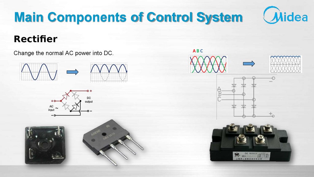
Main Components of Control SystemRectifier
Change the normal AC power into DC.
ABC
42.
Main Components of Control SystemRectifier
Turn off the power and let the inverter electrolytic capacitor discharge completely. Then use a tester to check
its continuity.
Needle-type Tester
Red
Black
~
+
-
~
Normal Resistance Value
∞
(Several MΩ)
43.
Main Components of Control SystemRectifier
Or test the voltage drop of diode.
Check the voltage drop of diode:
Less than 1V
44.
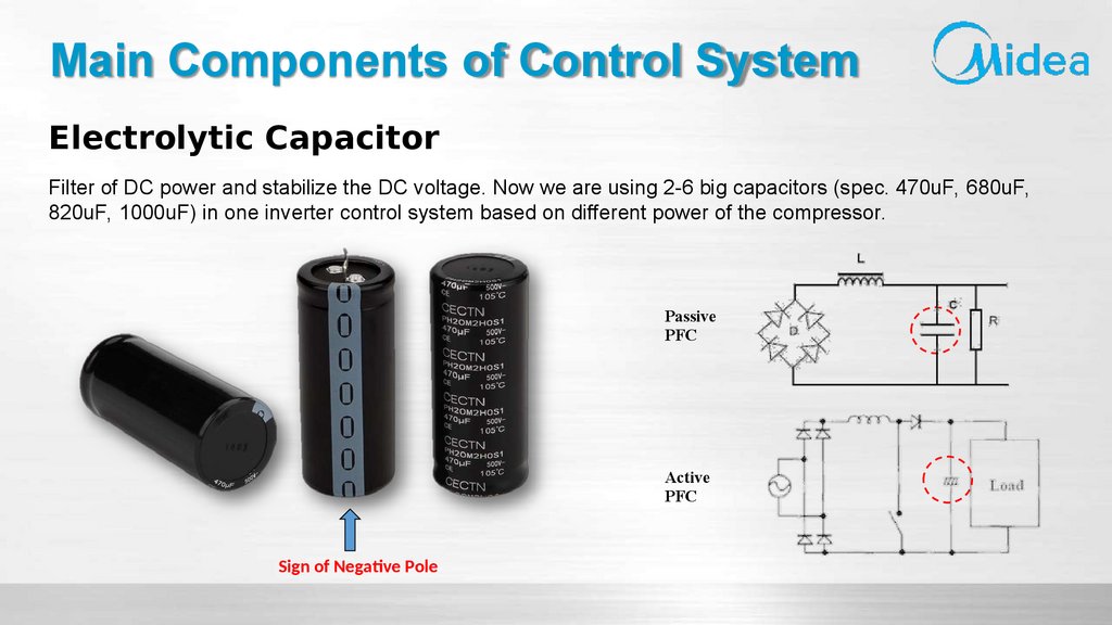
Main Components of Control SystemElectrolytic Capacitor
Filter of DC power and stabilize the DC voltage. Now we are using 2-6 big capacitors (spec. 470uF, 680uF,
820uF, 1000uF) in one inverter control system based on different power of the compressor.
Passive
PFC
Active
PFC
Sign of Negative Pole
45.
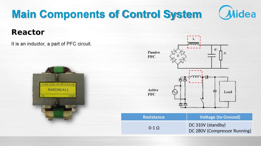
Main Components of Control SystemReactor
It is an inductor, a part of PFC circuit.
Passive
PFC
Active
PFC
Resistance
Voltage (to Ground)
0-1 Ω
DC 310V (standby)
DC 280V (Compressor Running)
46.
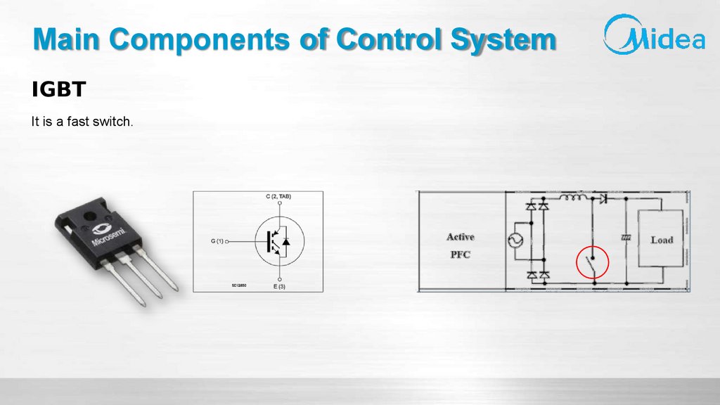
Main Components of Control SystemIGBT
It is a fast switch.
47.
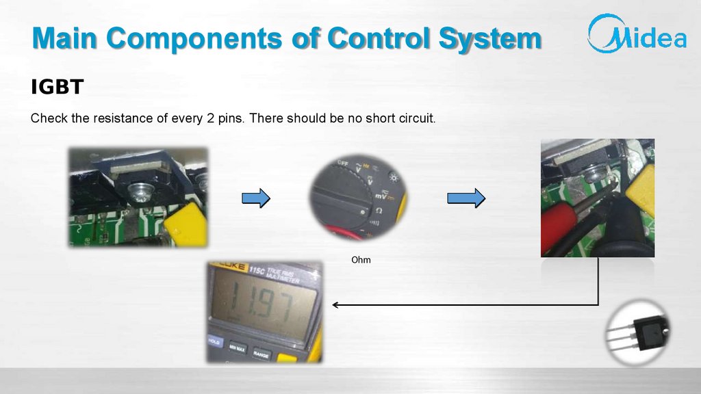
Main Components of Control SystemIGBT
Check the resistance of every 2 pins. There should be no short circuit.
Ohm
48.
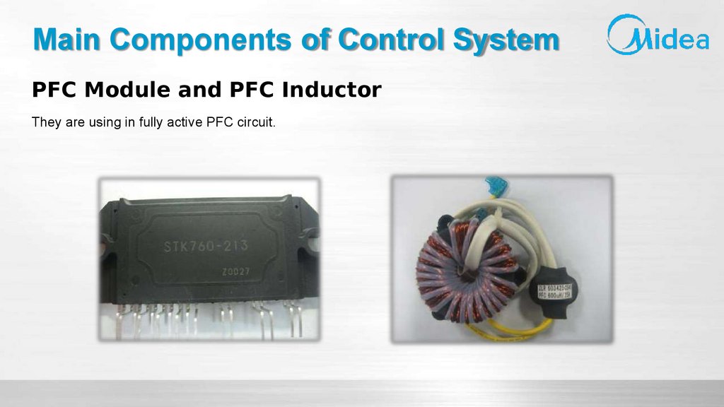
Main Components of Control SystemPFC Module and PFC Inductor
They are using in fully active PFC circuit.
49.
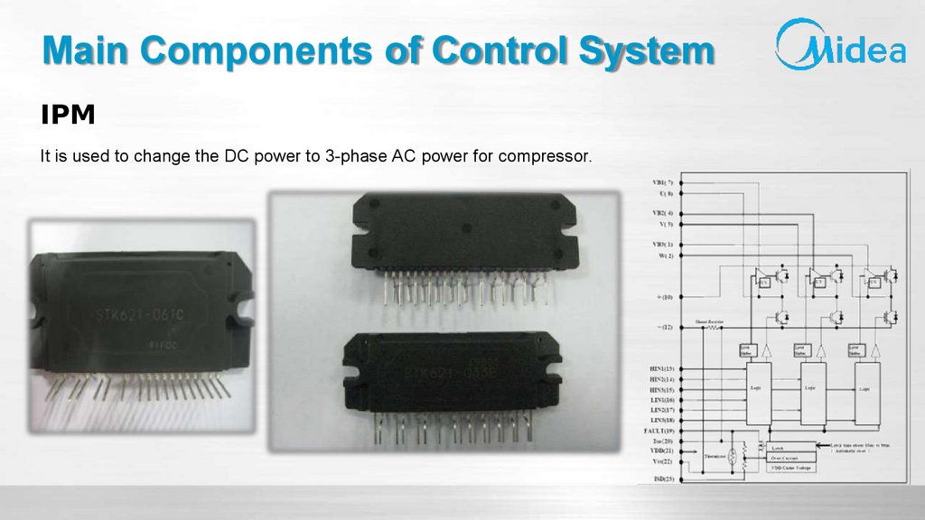
Main Components of Control SystemIPM
It is used to change the DC power to 3-phase AC power for compressor.
50.
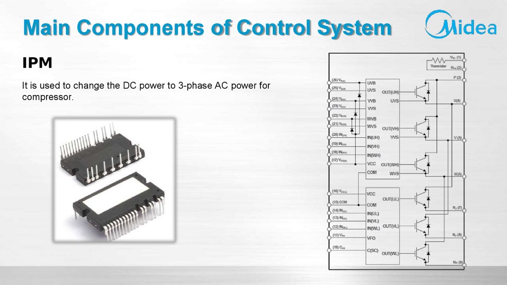
Main Components of Control SystemIPM
It is used to change the DC power to 3-phase AC power for
compressor.
51.
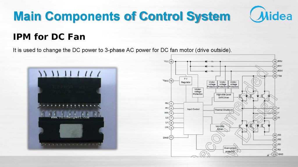
Main Components of Control SystemIPM for DC Fan
It is used to change the DC power to 3-phase AC power for DC fan motor (drive outside).
52.
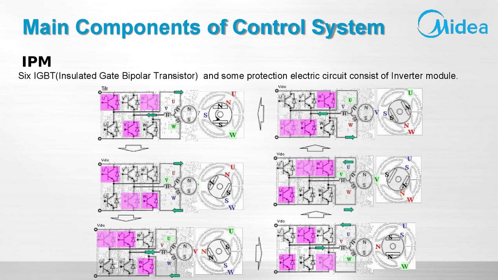
Main Components of Control SystemIPM
Six IGBT(Insulated Gate Bipolar Transistor) and some protection electric circuit consist of Inverter module.
53.
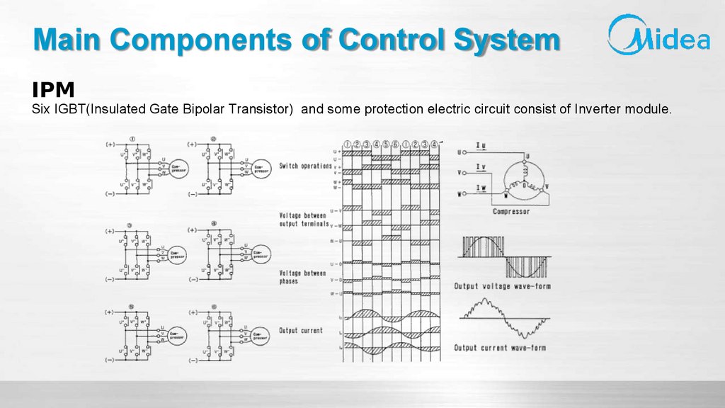
Main Components of Control SystemIPM
Six IGBT(Insulated Gate Bipolar Transistor) and some protection electric circuit consist of Inverter module.
54.
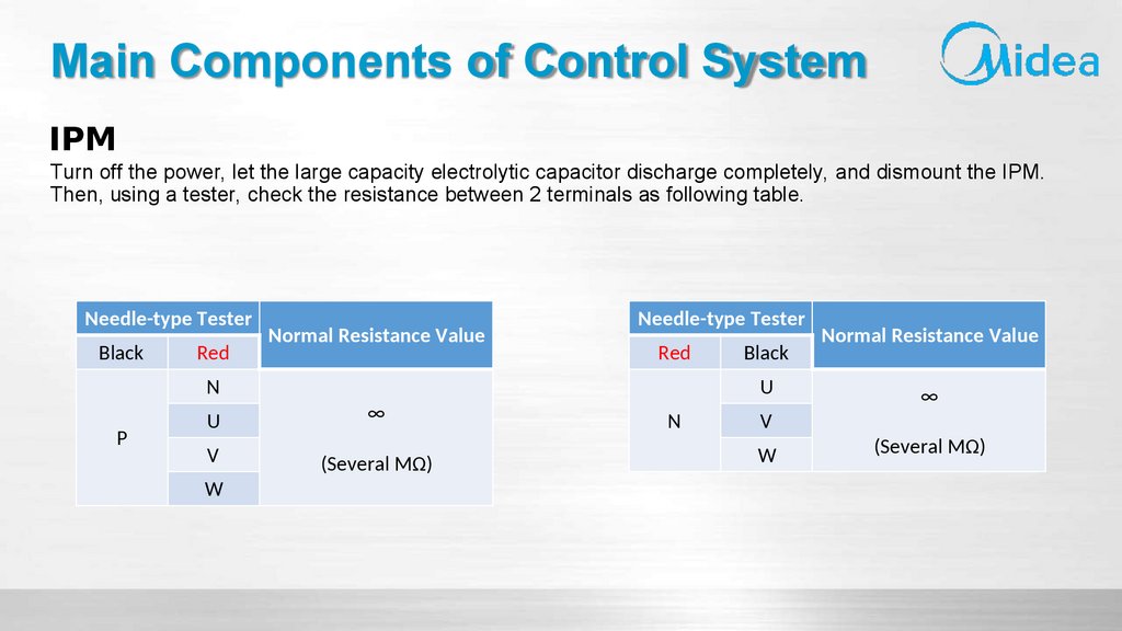
Main Components of Control SystemIPM
Turn off the power, let the large capacity electrolytic capacitor discharge completely, and dismount the IPM.
Then, using a tester, check the resistance between 2 terminals as following table.
Needle-type Tester
Black
Red
N
P
Normal Resistance Value
U
∞
V
(Several MΩ)
W
Needle-type Tester
Red
Black
U
N
V
W
Normal Resistance Value
∞
(Several MΩ)
55.
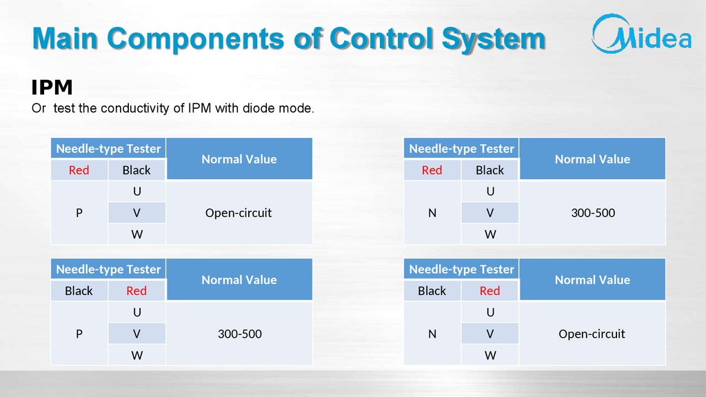
Main Components of Control SystemIPM
Or test the conductivity of IPM with diode mode.
Needle-type Tester
Red
Black
Normal Value
Needle-type Tester
Red
U
P
V
U
Open-circuit
N
W
Needle-type Tester
Black
Red
V
W
V
300-500
W
Normal Value
Needle-type Tester
Black
U
P
Black
Normal Value
Red
Normal Value
U
300-500
N
V
W
Open-circuit
56.
Troubleshooting Process57.
Troubleshooting ProcessLooks like there's no electricity ( Type A )
Malfunction
There is an error code on Display Panel or Debugging Board ( Type B )
58.
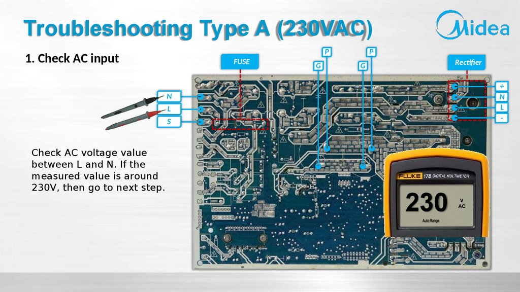
Troubleshooting Type A (230VAC)1. Check AC input
FUSE
P
G
P
Rectifier
G
+
N
L
-
N
L
S
Check AC voltage value
between L and N. If the
measured value is around
230V, then go to next step.
230
V
AC
59.
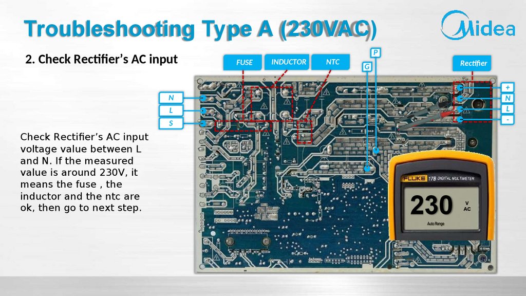
Troubleshooting Type A (230VAC)2. Check Rectifier’s AC input
FUSE
INDUCTOR
NTC
P
Rectifier
G
+
N
L
-
N
L
S
Check Rectifier’s AC input
voltage value between L
and N. If the measured
value is around 230V, it
means the fuse , the
inductor and the ntc are
ok, then go to next step.
230
V
AC
60.
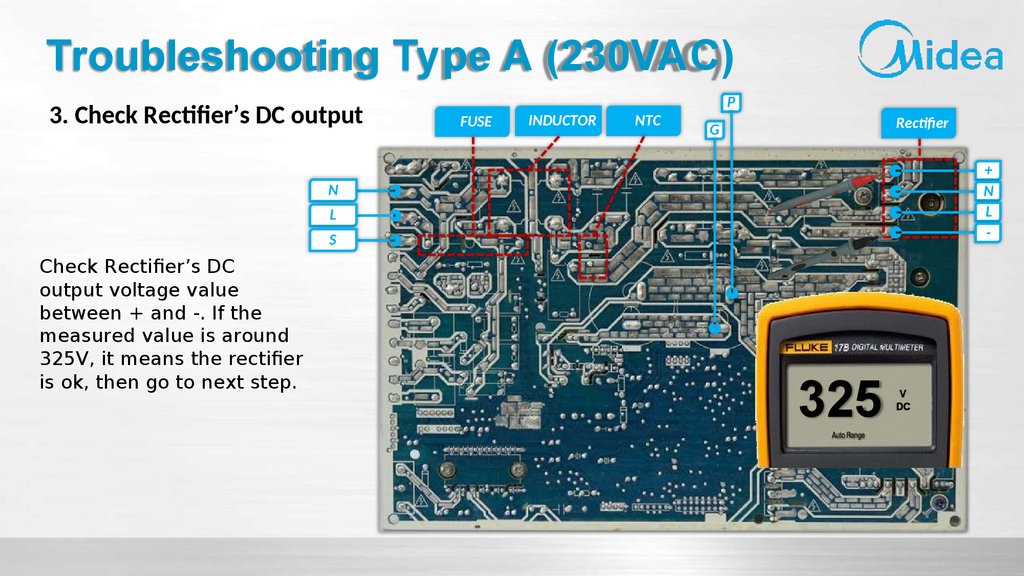
Troubleshooting Type A (230VAC)3. Check Rectifier’s DC output
FUSE
INDUCTOR
NTC
P
Rectifier
G
+
N
L
-
N
L
S
Check Rectifier’s DC
output voltage value
between + and -. If the
measured value is around
325V, it means the rectifier
is ok, then go to next step.
325
V
DC
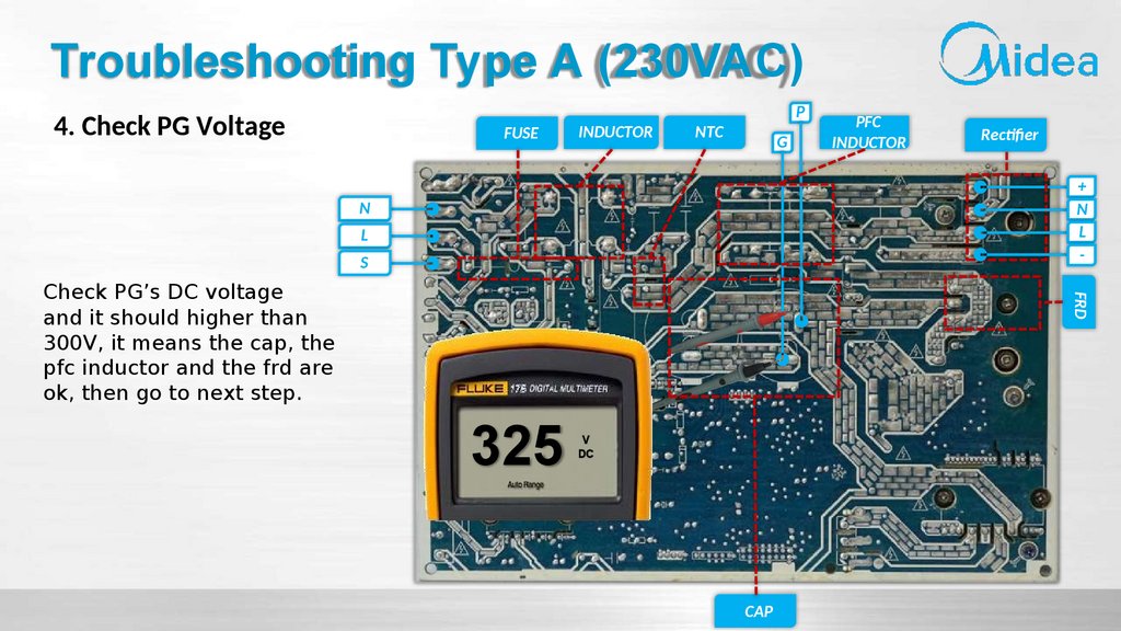
61.
Troubleshooting Type A (230VAC)4. Check PG Voltage
FUSE
INDUCTOR
P
NTC
G
PFC
INDUCTOR
Rectifier
+
N
L
-
N
L
S
FRD
Check PG’s DC voltage
and it should higher than
300V, it means the cap, the
pfc inductor and the frd are
ok, then go to next step.
325
V
DC
CAP
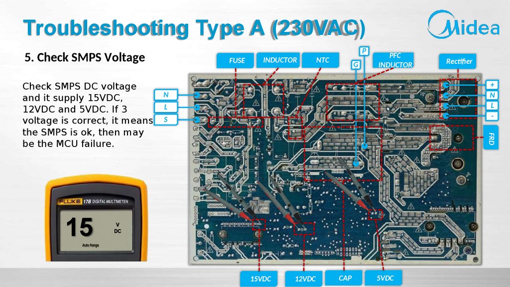
62.
Troubleshooting Type A (230VAC)5. Check SMPS Voltage
15
INDUCTOR
NTC
G
PFC
INDUCTOR
Rectifier
+
N
L
-
N
L
S
FRD
Check SMPS DC voltage
and it supply 15VDC,
12VDC and 5VDC. If 3
voltage is correct, it means
the SMPS is ok, then may
be the MCU failure.
FUSE
P
V
DC
15VDC
12VDC
CAP
5VDC
63.
Troubleshooting Type BDisplay Panel Error Code ( DP Error Code )
Debugging Board Error Code ( DB Error Code )
BOM Code: 17222000A55250
64.
Troubleshooting Type BOperation lamp
Timer lamp
☆ 1 time
X
☆ 2 times
X
☆ 3 times
X
☆ 4 times
X
☆ 5 times
X
☆ 6 times
X
DP Error Code
☆ 7 times
X
Error Code Display Priority :
E0>E2>E3>E4>E5>E1>EC>F0>F1
>F2>F3>F4>F5>P0>P1>P4>P6
☆ 1 times
O
☆ 2 times
O
☆ 3 times
O
☆ 4 times
O
☆ 5 times
O
☆ 6 times
O
☆ 1 times
☆
☆ 2 times
☆
☆ 5 times
☆
Display
Meaning of Troubles
E0 Indoor unit EEPROM parameter error
E1 Indoor / outdoor units communication error
E2 Zero-crossing signal detection error (Not available for DC indoor fan motor)
E3 Indoor fan speed has been out of control
E4 Indoor room temperature sensor T1 open circuit or short circuit
E5 Evaporator coil temperature sensor T2 open circuit or short circuit
EC Refrigerant leakage detection
b Communication error between indoor PCB and display PCB
E6/E
F0 Over-current protection
F1 Outdoor ambient temperature sensor T4 open circuit or short circuit
F2 Condenser coil temperature sensor T3 open circuit or short circuit
F3 Compressor discharge temperature sensor T5 open circuit or short circuit
F4 Outdoor unit EEPROM parameter error
F5 Outdoor fan speed has been out of control (DC fan motor only)
P0 IPM malfunction or IGBT over-strong current protection
P1 DC voltage between P&N out of range
P4 Inverter compressor drive error
p7 AP mode is active but there is no WIFI kit installed
65.
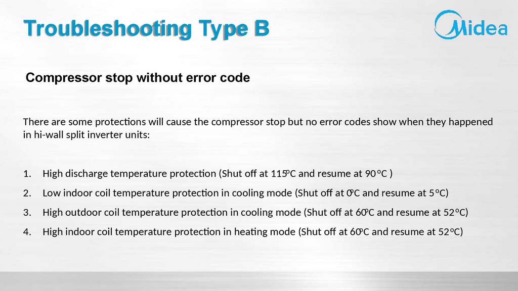
Troubleshooting Type BCompressor stop without error code
There are some protections will cause the compressor stop but no error codes show when they happened
in hi-wall split inverter units:
1.
High discharge temperature protection (Shut off at 115oC and resume at 90 oC )
2.
Low indoor coil temperature protection in cooling mode (Shut off at 0oC and resume at 5 oC)
3.
High outdoor coil temperature protection in cooling mode (Shut off at 60oC and resume at 52 oC)
4.
High indoor coil temperature protection in heating mode (Shut off at 60oC and resume at 52 oC)
66.
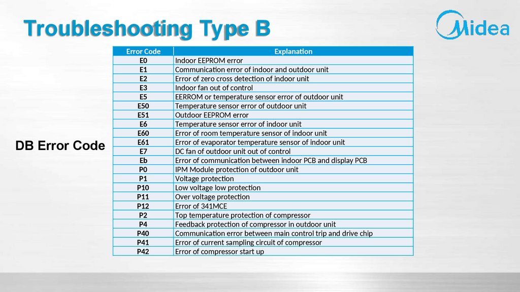
Troubleshooting Type BDB Error Code
Error Code
E0
E1
E2
E3
E5
E50
E51
E6
E60
E61
E7
Eb
P0
P1
P10
P11
P12
P2
P4
P40
P41
P42
Explanation
Indoor EEPROM error
Communication error of indoor and outdoor unit
Error of zero cross detection of indoor unit
Indoor fan out of control
EERROM or temperature sensor error of outdoor unit
Temperature sensor error of outdoor unit
Outdoor EEPROM error
Temperature sensor error of indoor unit
Error of room temperature sensor of indoor unit
Error of evaporator temperature sensor of indoor unit
DC fan of outdoor unit out of control
Error of communication between indoor PCB and display PCB
IPM Module protection of outdoor unit
Voltage protection
Low voltage low protection
Over voltage protection
Error of 341MCE
Top temperature protection of compressor
Feedback protection of compressor in outdoor unit
Communication error between main control trip and drive chip
Error of current sampling circuit of compressor
Error of compressor start up
67.
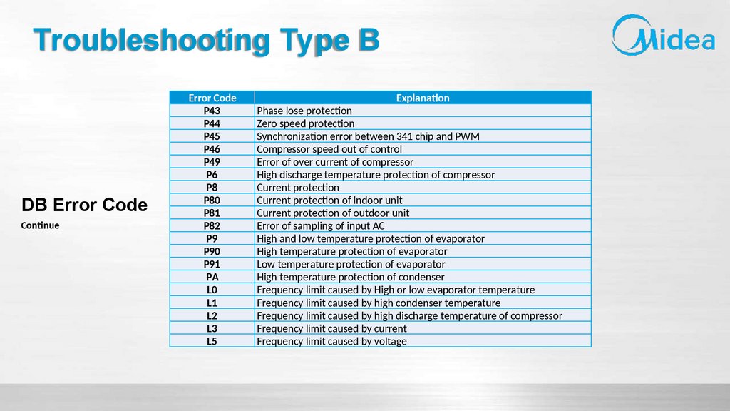
Troubleshooting Type BDB Error Code
Continue
Error Code
P43
P44
P45
P46
P49
P6
P8
P80
P81
P82
P9
P90
P91
PA
L0
L1
L2
L3
L5
Explanation
Phase lose protection
Zero speed protection
Synchronization error between 341 chip and PWM
Compressor speed out of control
Error of over current of compressor
High discharge temperature protection of compressor
Current protection
Current protection of indoor unit
Current protection of outdoor unit
Error of sampling of input AC
High and low temperature protection of evaporator
High temperature protection of evaporator
Low temperature protection of evaporator
High temperature protection of condenser
Frequency limit caused by High or low evaporator temperature
Frequency limit caused by high condenser temperature
Frequency limit caused by high discharge temperature of compressor
Frequency limit caused by current
Frequency limit caused by voltage
68.
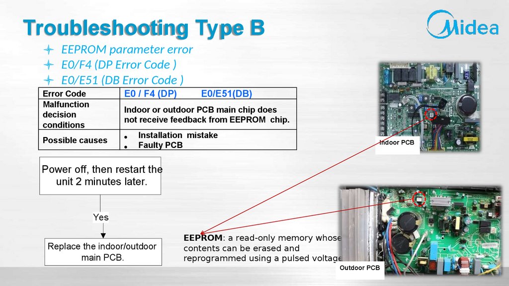
Troubleshooting Type BEEPROM parameter error
E0/F4 (DP Error Code )
E0/E51 (DB Error Code )
Error Code
Malfunction
decision
conditions
E0 / F4 (DP)
Possible causes
E0/E51(DB)
Indoor or outdoor PCB main chip does
not receive feedback from EEPROM chip.
Installation mistake
Faulty PCB
Indoor PCB
Power off, then restart the
unit 2 minutes later.
Yes
Replace the indoor/outdoor
main PCB.
EEPROM: a read-only memory whose
contents can be erased and
reprogrammed using a pulsed voltage
Outdoor PCB
69.
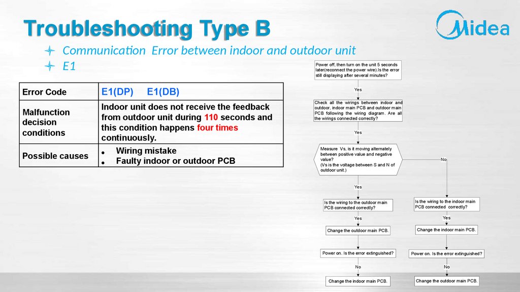
Troubleshooting Type BCommunication Error between indoor and outdoor unit
E1
Power off, then turn on the unit 5 seconds
later(reconnect the power wire).Is the error
still displaying after several minutes?
Error Code
E1(DP)
Malfunction
decision
conditions
Indoor unit does not receive the feedback
from outdoor unit during 110 seconds and
this condition happens four times
continuously.
Possible causes
E1(DB)
Wiring mistake
Faulty indoor or outdoor PCB
Yes
Check all the wirings between indoor and
outdoor, indoor main PCB and outdoor main
PCB following the wiring diagram. Are all
the wirings connected correctly?
Yes
Measure Vs, is it moving alternately
between positive value and negative
value?
(Vs is the voltage between S and N of
outdoor unit.)
No
Yes
Is the wiring to the outdoor main
PCB connected correctly?
Is the wiring to the indoor main
PCB connected correctly?
Yes
Yes
Change the outdoor main PCB.
Change the indoor main PCB.
Power on. Is the error extinguished?
Power on. Is the error extinguished?
No
No
Change the indoor main PCB.
Change the outdoor main PCB.
70.
Basic InformationFeatures
Faults without codes
Display
Electric control
Error Code
Troubleshooting
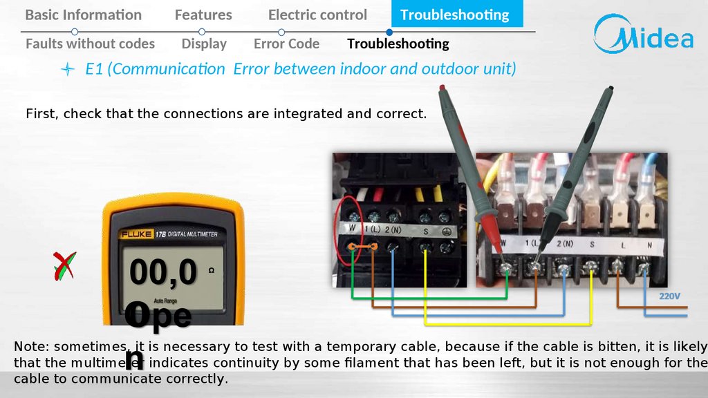
Troubleshooting
E1 (Communication Error between indoor and outdoor unit)
First, check that the connections are integrated and correct.
00,0
0
Ope
n
Ω
220V
Note: sometimes, it is necessary to test with a temporary cable, because if the cable is bitten, it is likely
that the multimeter indicates continuity by some filament that has been left, but it is not enough for the
cable to communicate correctly.
71.
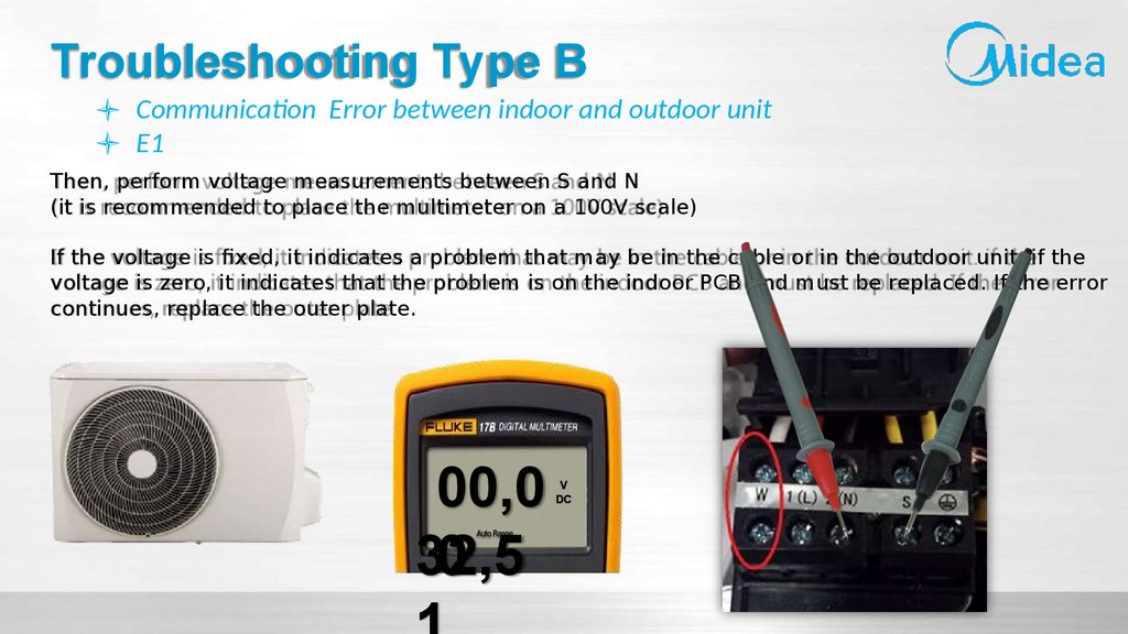
Troubleshooting Type BCommunication Error between indoor and outdoor unit
E1
Then, perform voltage measurements between S and N
(it is recommended to place the multimeter on a 100V scale)
If the voltage is fixed, it indicates a problem that may be in the cable or in the outdoor unit. if the
voltage is zero, it indicates that the problem is on the indoor PCB and must be replaced. If the error
continues, replace the outer plate.
00,0
32,5
0
V
DC
72.
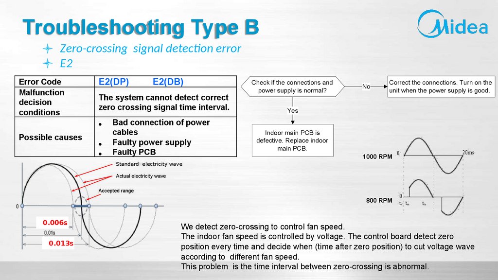
Troubleshooting Type BZero-crossing signal detection error
E2
Error Code
Malfunction
decision
conditions
E2(DP)
The system cannot detect correct
zero crossing signal time interval.
Possible causes
E2(DB)
Bad connection of power
cables
Faulty power supply
Faulty PCB
Standard electricity wave
Check if the connections and
power supply is normal?
No
Correct the connections. Turn on the
unit when the power supply is good.
Yes
Indoor main PCB is
defective. Replace indoor
main PCB.
1000 RPM
Actual electricity wave
Accepted range
800 RPM
0.006s
0.013s
We detect zero-crossing to control fan speed.
The indoor fan speed is controlled by voltage. The control board detect zero
position every time and decide when (time after zero position) to cut voltage wave
according to different fan speed.
This problem is the time interval between zero-crossing is abnormal.
73.
Troubleshooting Type BFan speed is out of control
E3/F5 (DP Error Code)
E3/E7 (DB Error Code)
Shut off the power supply
and turn it on 5 seconds
later. Is it still displaying
the error code?
No
The unit operates normally.
Yes
Error Code
E3/F5(DP)
Malfunction
decision
conditions
When fan speed keeps too low (300RPM) for
certain time, the unit will stop and the LED
will display the failure.
Possible
causes
E3/E7(DB)
Wiring mistake
Faulty fan wheel (fan blade)
Faulty fan motor
Faulty PCB
Surge
Shut off the power supply,
rotate the fan by hand.
Does it rotate properly?
No
Find out the cause and
have it solved. For
example, check
whether the fan is
blocked or the bearing
is broken?
No
Correct the connections.
Yes
Check the wires of fan
motor. Are all the
connections good?
Yes
Check whether the fan
motor is normal through
index 1?
No
No
Yes
Check whether the main PCB is
normal through index 2?
Replace the fan
motor
No
Replace the
main PCB.
The
malfunction is
solved?
Yes
If the
malfunction is
still existing,
replace the
main PCB
74.
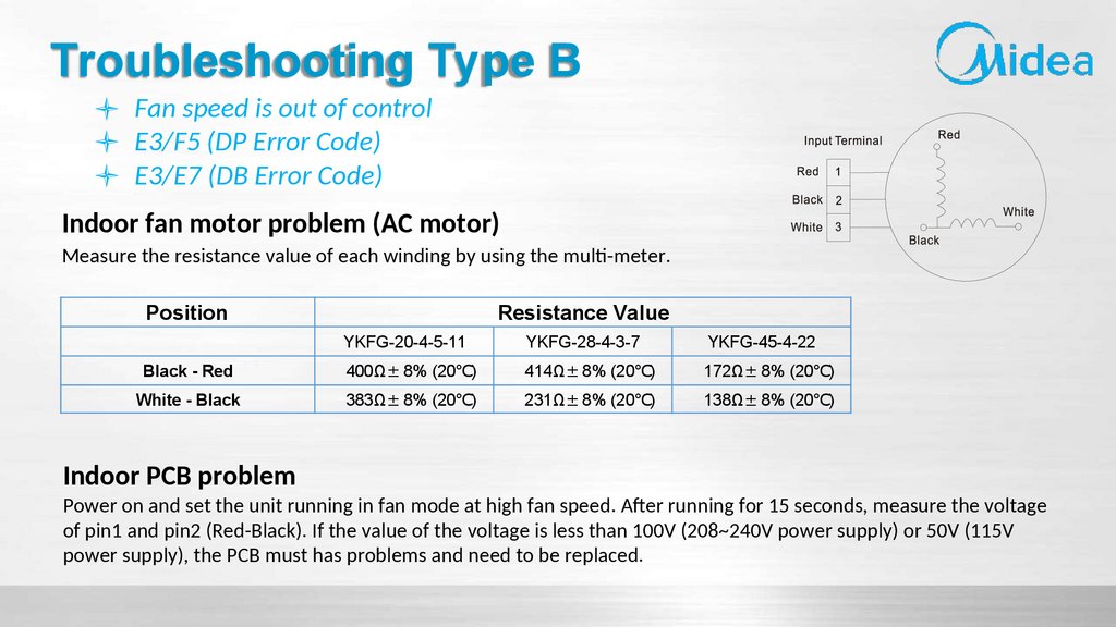
Troubleshooting Type BFan speed is out of control
E3/F5 (DP Error Code)
E3/E7 (DB Error Code)
Indoor fan motor problem (AC motor)
Measure the resistance value of each winding by using the multi-meter.
Position
Resistance Value
YKFG-20-4-5-11
YKFG-28-4-3-7
YKFG-45-4-22
Black - Red
400Ω± 8% (20℃)
414Ω± 8% (20℃)
172Ω± 8% (20℃)
White - Black
383Ω± 8% (20℃)
231Ω± 8% (20℃)
138Ω± 8% (20℃)
Indoor PCB problem
Power on and set the unit running in fan mode at high fan speed. After running for 15 seconds, measure the voltage
of pin1 and pin2 (Red-Black). If the value of the voltage is less than 100V (208~240V power supply) or 50V (115V
power supply), the PCB must has problems and need to be replaced.
75.
Troubleshooting Type BFan speed is out of control
E3/F5 (DP Error Code)
E3/E7 (DB Error Code)
Indoor fan motor problem (AC motor)
12,0
07,0
0
V
DC
76.
Troubleshooting Type BFan speed is out of control
E3/F5 (DP Error Code)
E3/E7 (DB Error Code)
Indoor fan motor problem (AC motor)
Check voltage value
between pins 1 and 3. If
the measured value is less
than 100V, the inner plate
is defective and must be
replaced.
175,
73,0
0
V
AC
77.
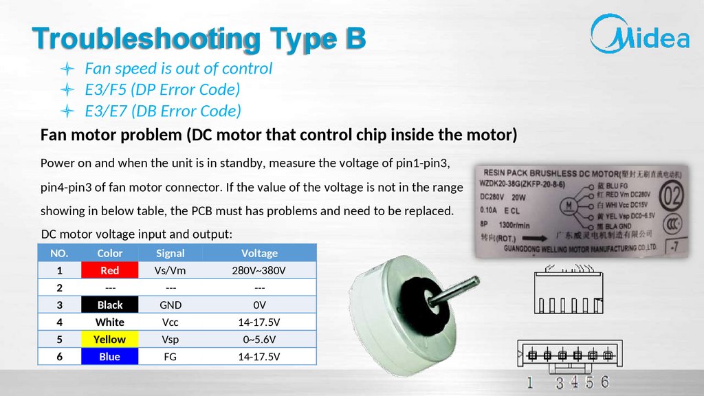
Troubleshooting Type BFan speed is out of control
E3/F5 (DP Error Code)
E3/E7 (DB Error Code)
Fan motor problem (DC motor that control chip inside the motor)
Power on and when the unit is in standby, measure the voltage of pin1-pin3,
pin4-pin3 of fan motor connector. If the value of the voltage is not in the range
showing in below table, the PCB must has problems and need to be replaced.
DC motor voltage input and output:
NO.
Color
Signal
Voltage
1
2
3
4
5
6
Red
--Black
White
Yellow
Blue
Vs/Vm
--GND
Vcc
Vsp
FG
280V~380V
--0V
14-17.5V
0~5.6V
14-17.5V
78.
Troubleshooting Type BFan speed is out of control
E3/F5 (DP Error Code)
E3/E7 (DB Error Code)
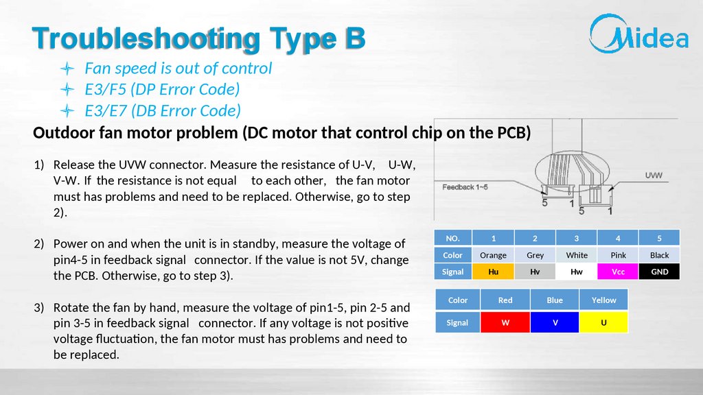
Outdoor fan motor problem (DC motor that control chip on the PCB)
1) Release the UVW connector. Measure the resistance of U-V, U-W,
V-W. If the resistance is not equal to each other, the fan motor
must has problems and need to be replaced. Otherwise, go to step
2).
2) Power on and when the unit is in standby, measure the voltage of
pin4-5 in feedback signal connector. If the value is not 5V, change
the PCB. Otherwise, go to step 3).
3) Rotate the fan by hand, measure the voltage of pin1-5, pin 2-5 and
pin 3-5 in feedback signal connector. If any voltage is not positive
voltage fluctuation, the fan motor must has problems and need to
be replaced.
NO.
1
2
3
4
5
Color
Orange
Grey
White
Pink
Black
Signal
Hu
Hv
Hw
Vcc
GND
Color
Red
Blue
Yellow
Signal
W
V
U
79.
Troubleshooting Type BFan speed is out of control
E3/F5 (DP Error Code)
E3/E7 (DB Error Code)
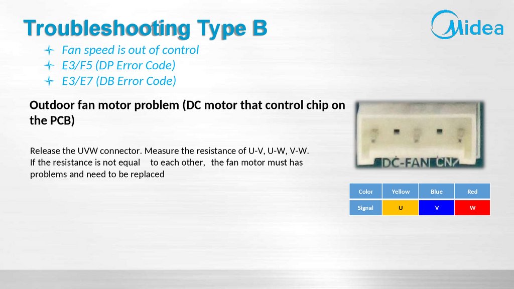
Outdoor fan motor problem (DC motor that control chip on
the PCB)
Release the UVW connector. Measure the resistance of U-V, U-W, V-W.
If the resistance is not equal to each other, the fan motor must has
problems and need to be replaced
Color
Yellow
Blue
Red
Signal
U
V
W
80.
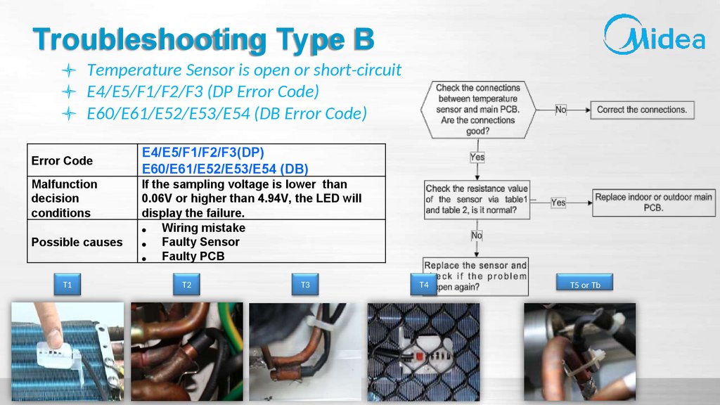
Troubleshooting Type BTemperature Sensor is open or short-circuit
E4/E5/F1/F2/F3 (DP Error Code)
E60/E61/E52/E53/E54 (DB Error Code)
Error Code
Malfunction
decision
conditions
Possible causes
T1
E4/E5/F1/F2/F3(DP)
E60/E61/E52/E53/E54 (DB)
If the sampling voltage is lower than
0.06V or higher than 4.94V, the LED will
display the failure.
Wiring mistake
Faulty Sensor
Faulty PCB
T2
T3
T4
T5 or Tb
81.
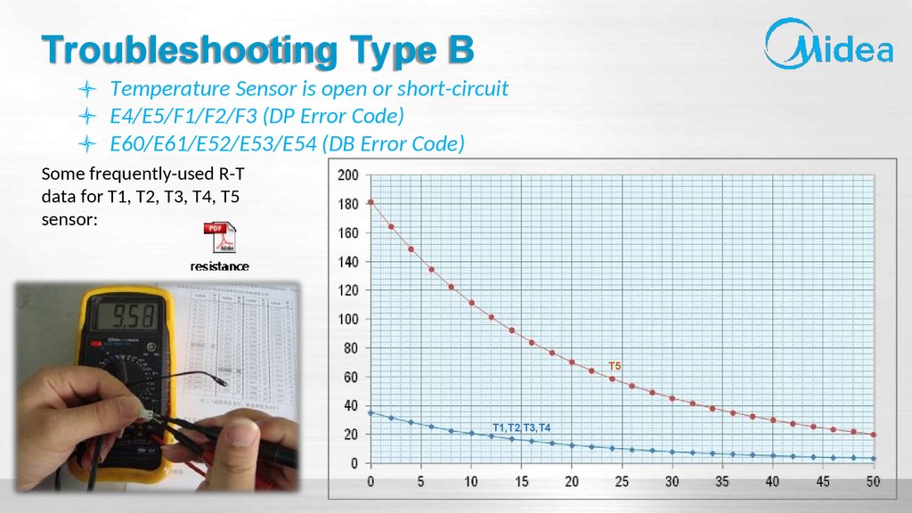
Troubleshooting Type BTemperature Sensor is open or short-circuit
E4/E5/F1/F2/F3 (DP Error Code)
E60/E61/E52/E53/E54 (DB Error Code)
Some frequently-used R-T
data for T1, T2, T3, T4, T5
sensor:
T5
T1,T2,T3,T4
82.
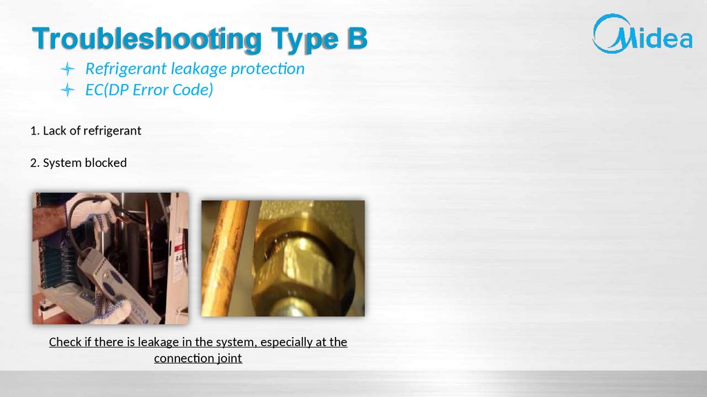
Troubleshooting Type BRefrigerant leakage protection
EC(DP Error Code)
Error Code
Malfunction
decision
conditions
Possible causes
EC(DP)
Define initial evaporator coil
temperature T2 when the compressor
just starts running as T cool .
In the beginning 8 minutes after the
compressor starts up, if T2 Tcool 2℃
does not keep continuous 4 seconds,
and this situation happens 3 times, the
display area will show “EC” and AC will
turn off.
Faulty T2 sensor
Faulty indoor PCB
System problems, such as leakage
or blocking.
83.
Troubleshooting Type BRefrigerant leakage protection
EC(DP Error Code)
1. Lack of refrigerant
2. System blocked
Check if there is leakage in the system, especially at the
connection joint
84.
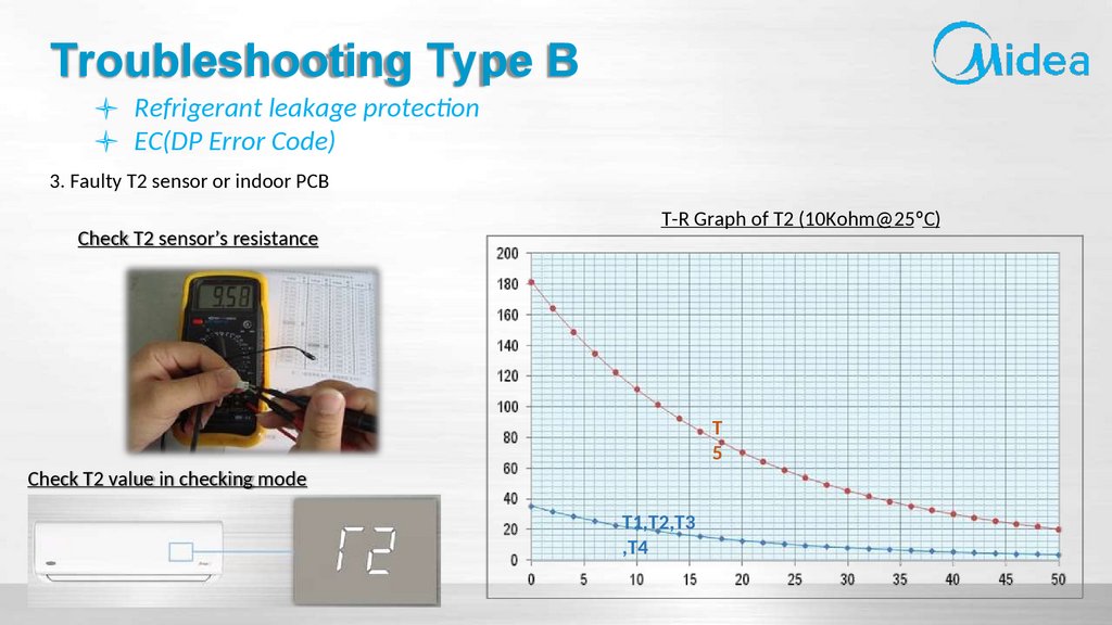
Troubleshooting Type BRefrigerant leakage protection
EC(DP Error Code)
3. Faulty T2 sensor or indoor PCB
Check T2 sensor’s resistance
T-R Graph of T2 (10Kohm@25ºC)
T
5
Check T2 value in checking mode
T1,T2,T3
,T4
85.
Troubleshooting Type BRefrigerant leakage protection
EC(DP Error Code)
4. Serpentine obstruction
5. Problem on indoor PCB
PCB damaged
System blocked or partial on T2
86.
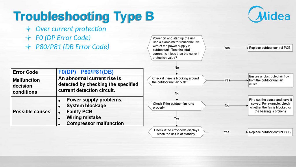
Troubleshooting Type BOver current protection
F0 (DP Error Code)
P80/P81 (DB Error Code)
Error Code
Malfunction
decision
conditions
F0(DP) P80/P81(DB)
An abnormal current rise is
detected by checking the specified
current detection circuit.
Possible causes
Power supply problems.
System blockage
Faulty PCB
Wiring mistake
Compressor malfunction
Power on and start up the unit.
Use a clamp meter round the live
wire of the power supply in
outdoor unit. Test the total
current. Is it less than the current
protection value?
Yes
Replace outdoor control PCB.
Yes
Ensure unobstructed air flow
from the outdoor unit air
outlet.
No
Find out the cause and have it
solved. For example, check
whether the fan is blocked or
the bearing is broken?
Yes
Replace outdoor control PCB.
No
Check if there is blocking around
the outdoor unit air outlet.
No
Check if the outdoor fan runs
properly.
Yes
Check if the error code displays
when the unit is at standby.
87.
Troubleshooting Type BOver current protection
F0 (DP Error Code)
P80/P81 (DB Error Code)
Verify Current
Clean Condenser
Verify Fan capacity
88.
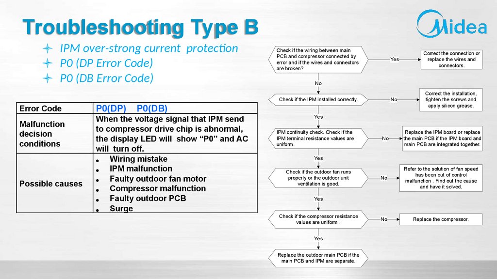
Troubleshooting Type BIPM over-strong current protection
P0 (DP Error Code)
P0 (DB Error Code)
Error Code
Malfunction
decision
conditions
Possible causes
P0(DP)
P0(DB)
When the voltage signal that IPM send
to compressor drive chip is abnormal,
the display LED will show “P0” and AC
will turn off.
Wiring mistake
IPM malfunction
Faulty outdoor fan motor
Compressor malfunction
Faulty outdoor PCB
Surge
Check if the wiring between main
PCB and compressor connected by
error and if the wires and connectors
are broken?
Yes
Correct the connection or
replace the wires and
connectors.
No
Correct the installation,
tighten the screws and
apply silicon grease.
No
Check if the IPM installed correctly.
Yes
IPM continuity check. Check if the
IPM terminal resistance values are
uniform.
No
Replace the IPM board or replace
the main PCB if the IPM board and
main PCB are integrated together.
No
Refer to the solution of fan speed
has been out of control
malfunction . Find out the cause
and have it solved.
No
Replace the compressor.
Yes
Check if the outdoor fan runs
properly or the outdoor unit
ventilation is good.
Yes
Check if the compressor resistance
values are uniform .
Yes
Replace the outdoor main PCB if the
main PCB and IPM are separate.
89.
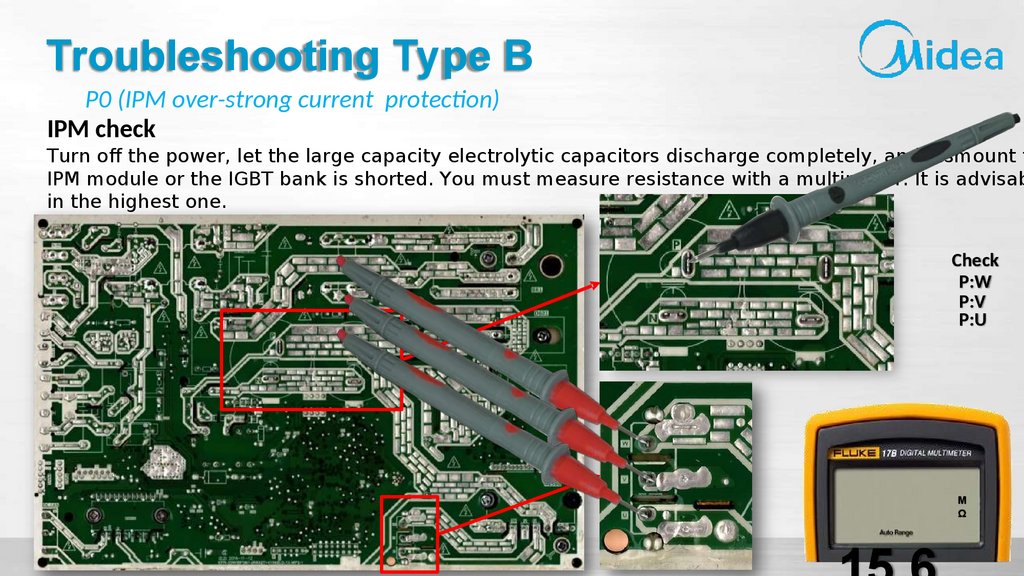
Troubleshooting Type BP0 (IPM over-strong current protection)
IPM check
Turn off the power, let the large capacity electrolytic capacitors discharge completely, and dismount t
IPM module or the IGBT bank is shorted. You must measure resistance with a multimeter. It is advisab
in the highest one.
Check
P:W
P:V
P:U
M
Ω
90.
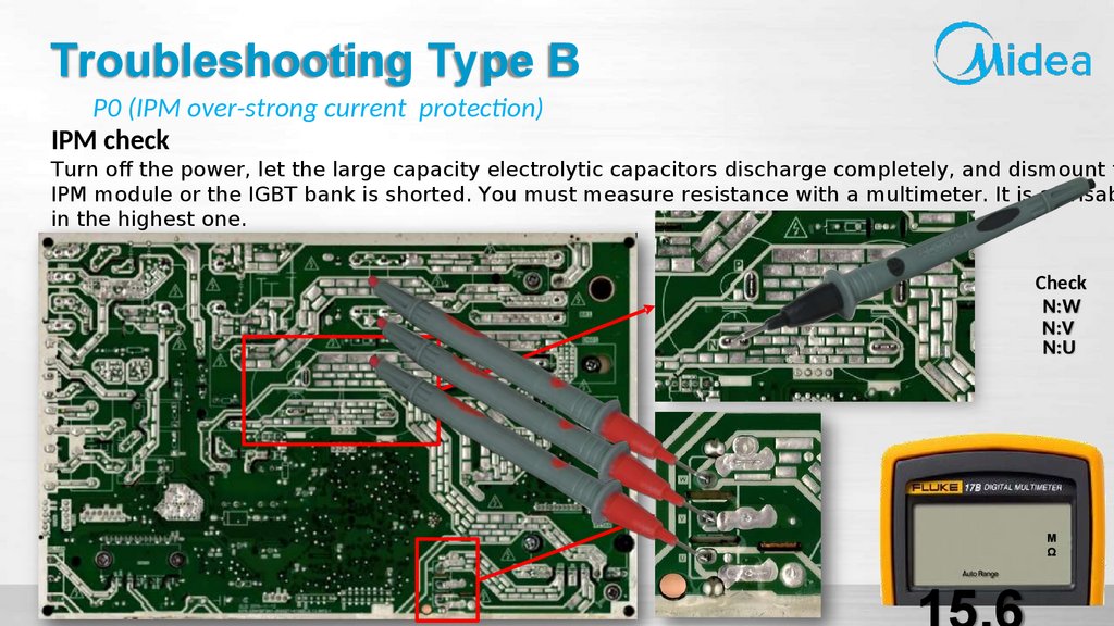
Troubleshooting Type BP0 (IPM over-strong current protection)
IPM check
Turn off the power, let the large capacity electrolytic capacitors discharge completely, and dismount t
IPM module or the IGBT bank is shorted. You must measure resistance with a multimeter. It is advisab
in the highest one.
Check
N:W
N:V
N:U
M
Ω
91.
Troubleshooting Type BP0 (IPM over-strong current protection)
Compressor check
Disconnect the compressor and check the resistance between U-V, V-W and U-W, and all 3 values should be equal.
If not, the compressor is faulty and should be replaced.
U
V
W
Compressor
model
U-V
V-W
U-W
ASN98D22U
EZ
DA130M1C31FZ
DA200S2C10MT
1.57Ω
(20℃)
1.77Ω
(20℃)
0.57Ω
(20℃)
Resistance Value Reference
ATM115D1U DA108X1CFZ
23EZ
1.89Ω
(20℃)
1.1Ω
(20℃)
02,1
2
0
Ω
DA130S1C20FZ
DA150S1C20FZ
DA250S2C30MT
0.95Ω
(20℃)
0.95Ω
(20℃)
0.55Ω
(20℃)
92.
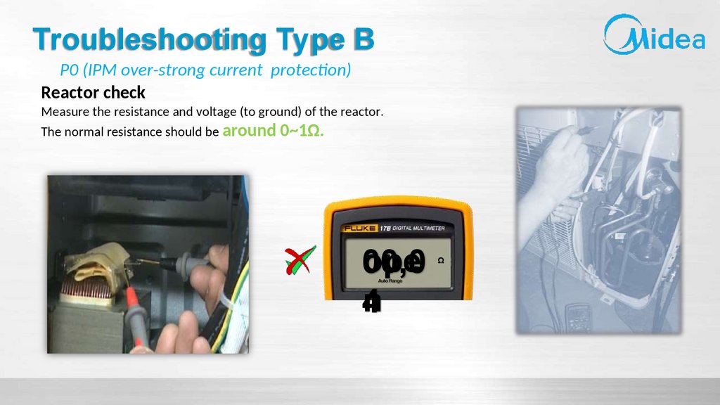
Troubleshooting Type BP0 (IPM over-strong current protection)
Reactor check
Measure the resistance and voltage (to ground) of the reactor.
The normal resistance should be around 0~1Ω.
ope
00,0
n
4
Ω
93.
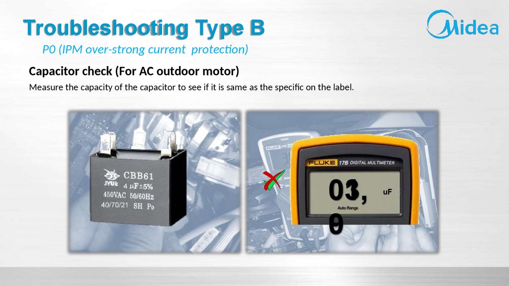
Troubleshooting Type BP0 (IPM over-strong current protection)
Capacitor check (For AC outdoor motor)
Measure the capacity of the capacitor to see if it is same as the specific on the label.
01,
03,
9
0
uF
94.
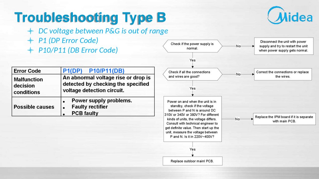
Troubleshooting Type BDC voltage between P&G is out of range
P1 (DP Error Code)
Check if the power supply is
normal.
P10/P11 (DB Error Code)
No
Disconnect the unit with power
supply and try to restart the unit
when power supply gets normal.
No
Correct the connections or replace
the wires.
No
Replace the IPM board if it is separate
with main PCB.
Yes
Error Code
Malfunction
decision
conditions
P1(DP)
An abnormal voltage rise or drop is
detected by checking the specified
voltage detection circuit.
Possible causes
P10/P11(DB)
Power supply problems.
Faulty rectifier
PCB faulty
Check if all the connections
and wires are good?
Yes
Power on and when the unit is in
standby, check if the voltage
between P and N is around DC
310V or 340V or 380V? For different
kinds of units, the voltage differs.
Consult with technical engineer to
get definite value. Then start up the
unit, measure the voltage between
P and N. Is it in 220V~400V?
Yes
Replace outdoor mainl PCB.
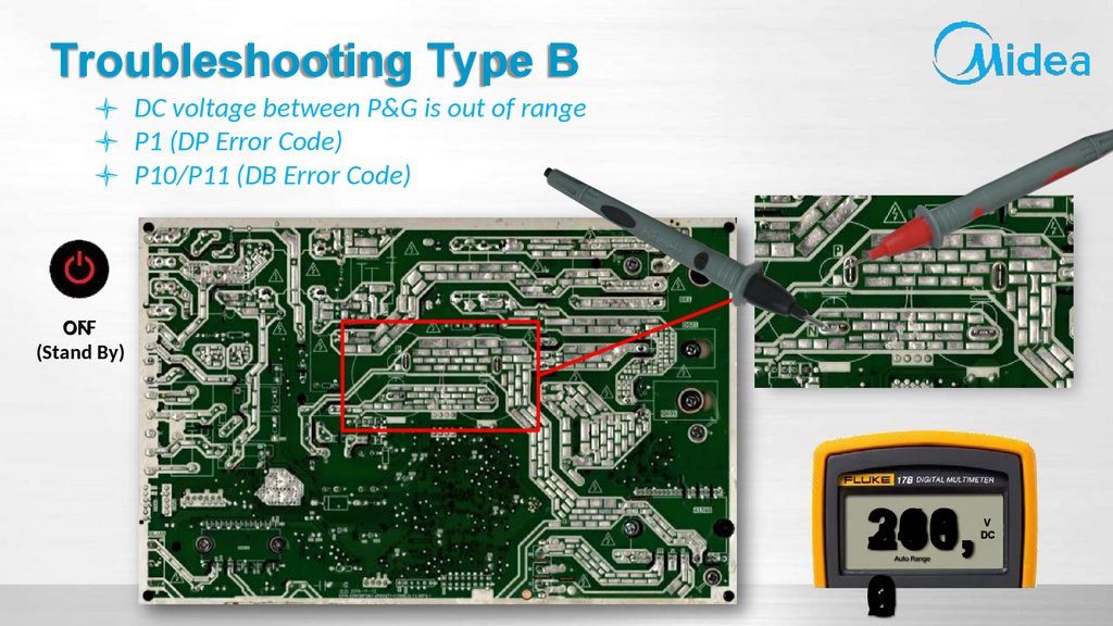
95.
Troubleshooting Type BDC voltage between P&G is out of range
P1 (DP Error Code)
P10/P11 (DB Error Code)
OFF
ON
(Stand By)
240,
306,
268.
310,
299,
281,
0
9
2
3
1
V
DC
96.
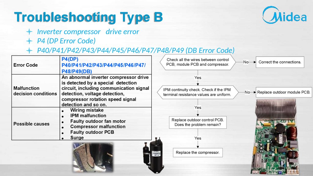
Troubleshooting Type BInverter compressor drive error
P4 (DP Error Code)
P40/P41/P42/P43/P44/P45/P46/P47/P48/P49 (DB Error Code)
Error Code
P4(DP)
P40/P41/P42/P43/P44/P45/P46/P47/
P48/P49(DB)
An abnormal inverter compressor drive
is detected by a special detection
Malfunction
circuit, including communication signal
decision conditions detection, voltage detection,
compressor rotation speed signal
detection and so on.
Wiring mistake
IPM malfunction
Faulty outdoor fan motor
Possible causes
Compressor malfunction
Faulty outdoor PCB
Surge
Check all the wires between control
PCB, module PCB and compressor.
No
Correct the connections.
No
Replace outdoor module PCB.
Yes
IPM continuity check. Check if the IPM
terminal resistance values are uniform.
Yes
Replace outdoor control PCB.
Does the problem remain?
Yes
Replace the compressor.
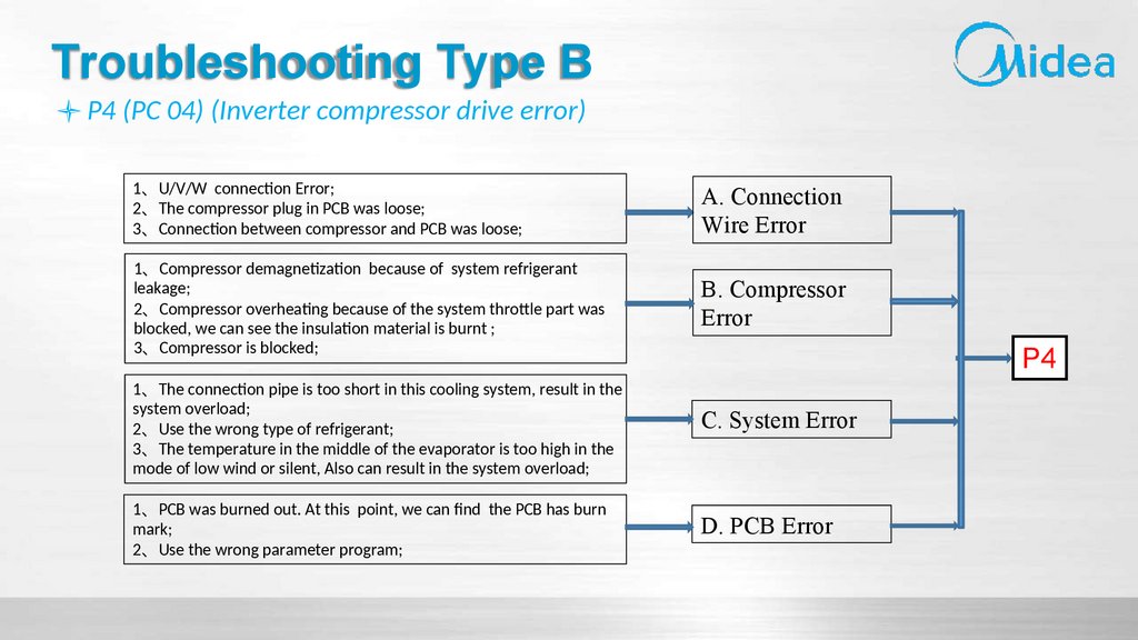
97.
Troubleshooting Type BP4 (PC 04) (Inverter compressor drive error)
1、U/V/W connection Error;
2、The compressor plug in PCB was loose;
3、Connection between compressor and PCB was loose;
A. Connection
Wire Error
1、Compressor demagnetization because of system refrigerant
leakage;
2、Compressor overheating because of the system throttle part was
blocked, we can see the insulation material is burnt ;
3、Compressor is blocked;
B. Compressor
Error
1、The connection pipe is too short in this cooling system, result in the
system overload;
2、Use the wrong type of refrigerant;
3、The temperature in the middle of the evaporator is too high in the
mode of low wind or silent, Also can result in the system overload;
1、PCB was burned out. At this point, we can find the PCB has burn
mark;
2、Use the wrong parameter program;
P4
C. System Error
D. PCB Error
98.
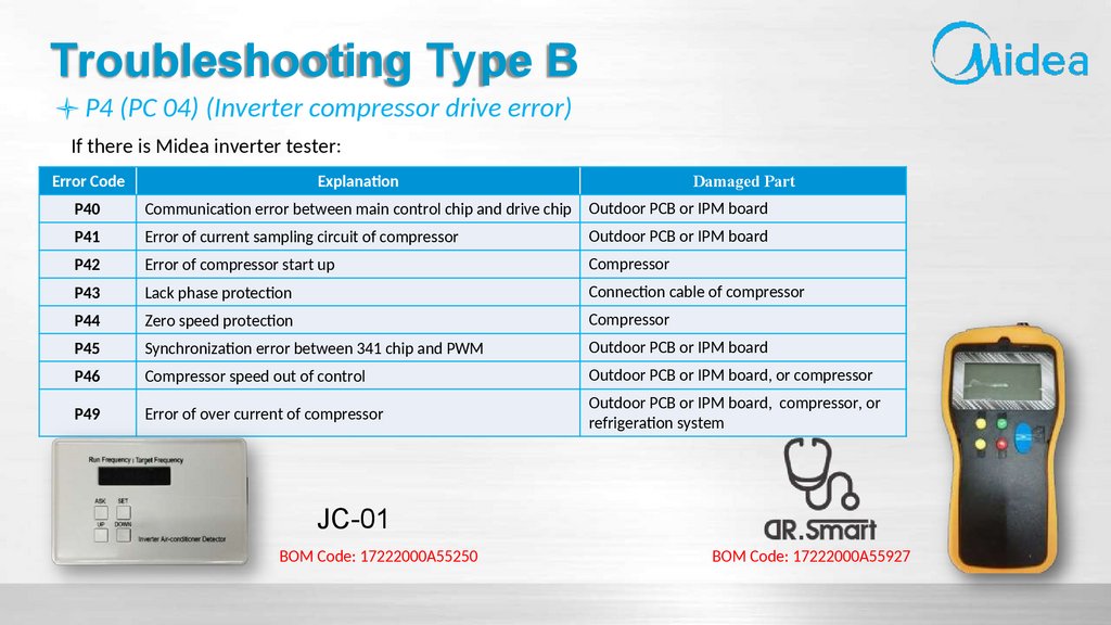
Troubleshooting Type BP4 (PC 04) (Inverter compressor drive error)
If there is Midea inverter tester:
Error Code
Explanation
Damaged Part
P40
Communication error between main control chip and drive chip
Outdoor PCB or IPM board
P41
Error of current sampling circuit of compressor
Outdoor PCB or IPM board
P42
Error of compressor start up
Compressor
P43
Lack phase protection
Connection cable of compressor
P44
Zero speed protection
Compressor
P45
Synchronization error between 341 chip and PWM
Outdoor PCB or IPM board
P46
Compressor speed out of control
Outdoor PCB or IPM board, or compressor
P49
Error of over current of compressor
Outdoor PCB or IPM board, compressor, or
refrigeration system
JC-01
BOM Code: 17222000A55250
BOM Code: 17222000A55927
99.
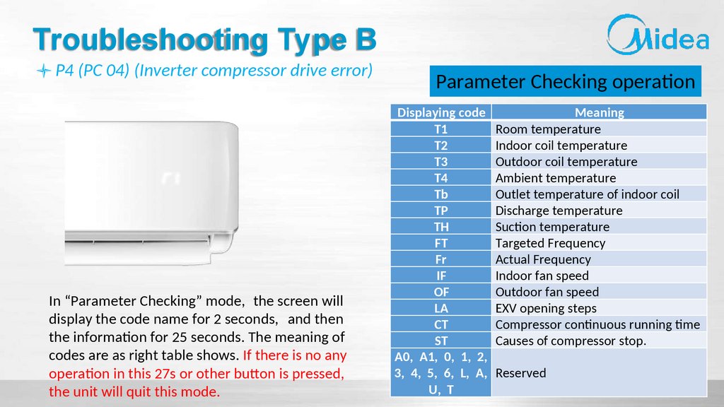
Troubleshooting Type BP4 (PC 04) (Inverter compressor drive error)
In “Parameter Checking” mode, the screen will
display the code name for 2 seconds, and then
the information for 25 seconds. The meaning of
codes are as right table shows. If there is no any
operation in this 27s or other button is pressed,
the unit will quit this mode.
Parameter Checking operation
Displaying code
Meaning
T1
Room temperature
T2
Indoor coil temperature
T3
Outdoor coil temperature
T4
Ambient temperature
Tb
Outlet temperature of indoor coil
TP
Discharge temperature
TH
Suction temperature
FT
Targeted Frequency
Fr
Actual Frequency
IF
Indoor fan speed
OF
Outdoor fan speed
LA
EXV opening steps
CT
Compressor continuous running time
ST
Causes of compressor stop.
A0, A1, 0, 1, 2,
3, 4, 5, 6, L, A, Reserved
U, T
100.
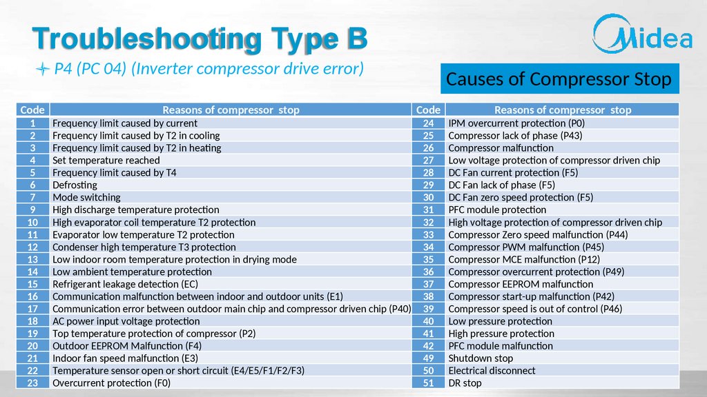
Troubleshooting Type BP4 (PC 04) (Inverter compressor drive error)
Code
1
2
3
4
5
6
7
9
10
11
12
13
14
15
16
17
18
19
20
21
22
23
Reasons of compressor stop
Frequency limit caused by current
Frequency limit caused by T2 in cooling
Frequency limit caused by T2 in heating
Set temperature reached
Frequency limit caused by T4
Defrosting
Mode switching
High discharge temperature protection
High evaporator coil temperature T2 protection
Evaporator low temperature T2 protection
Condenser high temperature T3 protection
Low indoor room temperature protection in drying mode
Low ambient temperature protection
Refrigerant leakage detection (EC)
Communication malfunction between indoor and outdoor units (E1)
Communication error between outdoor main chip and compressor driven chip (P40)
AC power input voltage protection
Top temperature protection of compressor (P2)
Outdoor EEPROM Malfunction (F4)
Indoor fan speed malfunction (E3)
Temperature sensor open or short circuit (E4/E5/F1/F2/F3)
Overcurrent protection (F0)
Causes of Compressor Stop
Code
24
25
26
27
28
29
30
31
32
33
34
35
36
37
38
39
40
41
42
49
50
51
Reasons of compressor stop
IPM overcurrent protection (P0)
Compressor lack of phase (P43)
Compressor malfunction
Low voltage protection of compressor driven chip
DC Fan current protection (F5)
DC Fan lack of phase (F5)
DC Fan zero speed protection (F5)
PFC module protection
High voltage protection of compressor driven chip
Compressor Zero speed malfunction (P44)
Compressor PWM malfunction (P45)
Compressor MCE malfunction (P12)
Compressor overcurrent protection (P49)
Compressor EEPROM malfunction
Compressor start-up malfunction (P42)
Compressor speed is out of control (P46)
Low pressure protection
High pressure protection
PFC module malfunction
Shutdown stop
Electrical disconnect
DR stop
101.
Troubleshooting Type BP4 (PC 04) (Inverter compressor drive error)
Confirm all the wirings of outdoor unit power, main PCB and compressor are correct or not, and whether
the connecting is loose.
102.
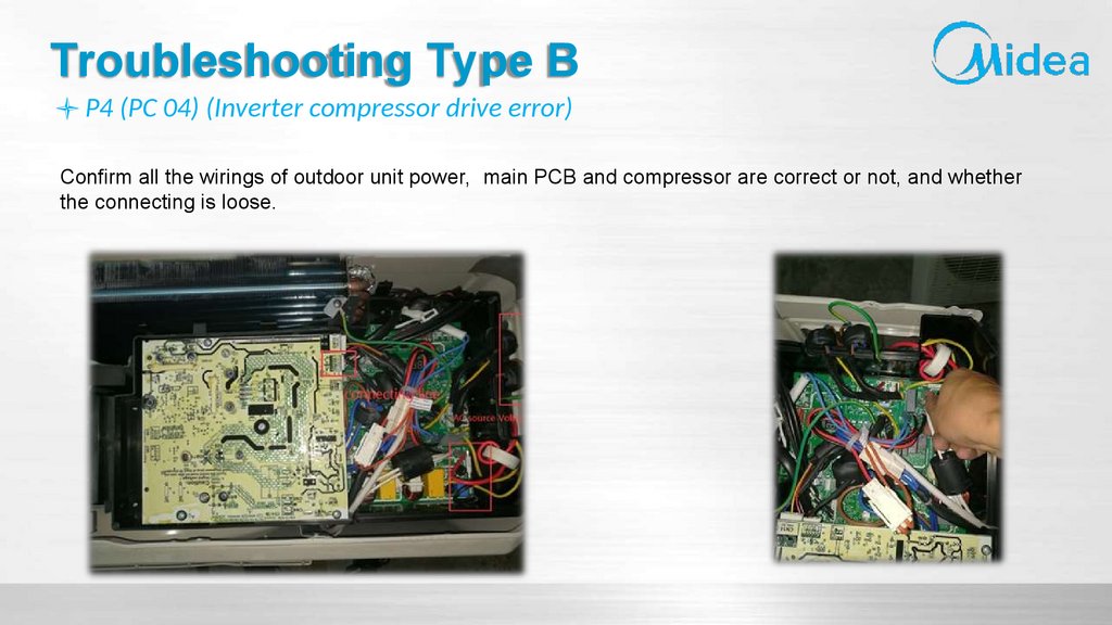
Troubleshooting Type BP4 (PC 04) (Inverter compressor drive error)
Confirm all the wirings of outdoor unit power, main PCB and compressor are correct or not, and whether
the connecting is loose.
103.
Troubleshooting Type BP4 (PC 04) (Inverter compressor drive error)
To check whether the compressor sleeve is brown. If yes, it is preliminarily judged as high
temperature demagnetization of the compressor
104.
THANKSFOR YOUR ATTENTION
Midea Strategic Partners: