


 electronics
 industry
Similar presentations:
")
")

")
![PBA Repair Guide [GT-S8000]](https://cf.ppt-online.org/files/thumb/t/tIHBnfpml5G6E47aLocdVU0kDZQNvuejRhAMC8.jpg "PBA Repair Guide [GT-S8000]")


Galaxy S5 H/W. Repair guide
1.
Galaxy S5 H/W Repair GuideMarch, 2014
This material is a property of Samsung Electronics Co., Ltd. Any unauthorized use of this material can be punished
under applicable International and/or domestic law.
- This document cannot be used without Samsung’s Authorization -
2.
NoticeAll functionality, features, specifications and other product information provided in this
document including, but not limited to, the benefits, design, pricing, components,
performance, availability, and capabilities of the product are subject to change without
notice or obligation.
Samsung reserves the right to make changes to this document and the product described
herein, at anytime, without obligation on Samsung to provide notification of such change.
- This document cannot be used without Samsung’s Authorization -
3.
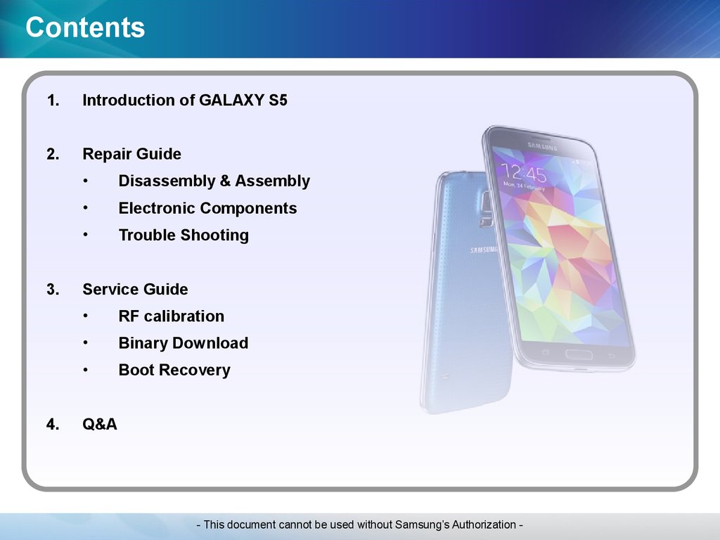
Contents1.
Introduction of GALAXY S5
2.
Repair Guide
3.
4.
Disassembly & Assembly
Electronic Components
Trouble Shooting
Service Guide
RF calibration
Binary Download
Boot Recovery
Q&A
- This document cannot be used without Samsung’s Authorization -
4.
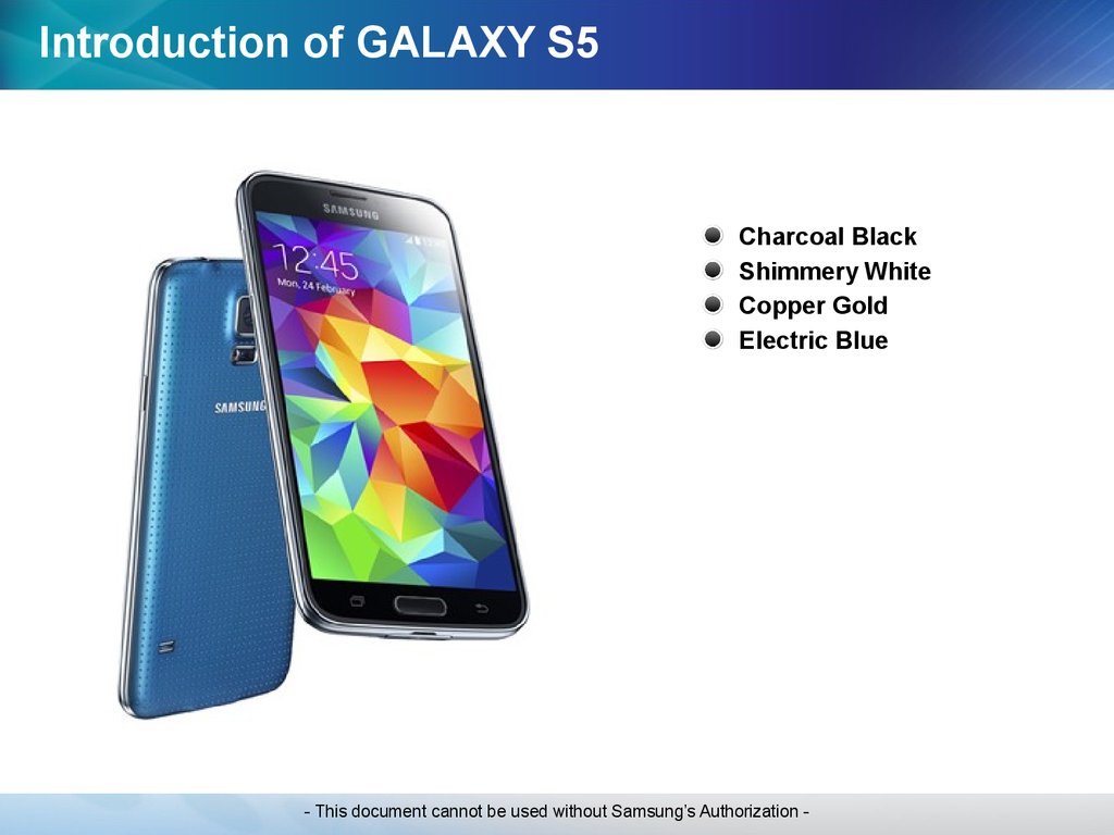
Introduction of GALAXY S5Charcoal Black
Shimmery White
Copper Gold
Electric Blue
- This document cannot be used without Samsung’s Authorization -
5.
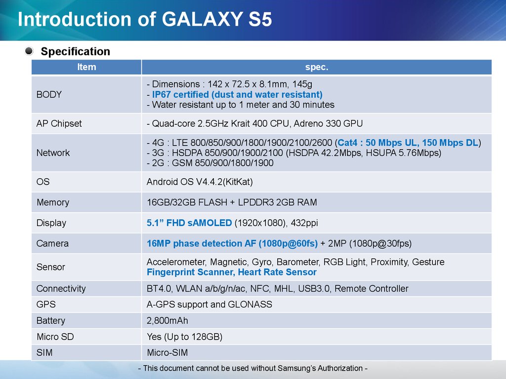
Introduction of GALAXY S5Specification
Item
spec.
BODY
- Dimensions : 142 x 72.5 x 8.1mm, 145g
- IP67 certified (dust and water resistant)
- Water resistant up to 1 meter and 30 minutes
AP Chipset
- Quad-core 2.5GHz Krait 400 CPU, Adreno 330 GPU
Network
- 4G : LTE 800/850/900/1800/1900/2100/2600 (Cat4 : 50 Mbps UL, 150 Mbps DL)
- 3G : HSDPA 850/900/1900/2100 (HSDPA 42.2Mbps, HSUPA 5.76Mbps)
- 2G : GSM 850/900/1800/1900
OS
Android OS V4.4.2(KitKat)
Memory
16GB/32GB FLASH + LPDDR3 2GB RAM
Display
5.1” FHD sAMOLED (1920x1080), 432ppi
Camera
16MP phase detection AF (1080p@60fs) + 2MP (1080p@30fps)
Sensor
Accelerometer, Magnetic, Gyro, Barometer, RGB Light, Proximity, Gesture
Fingerprint Scanner, Heart Rate Sensor
Connectivity
BT4.0, WLAN a/b/g/n/ac, NFC, MHL, USB3.0, Remote Controller
GPS
A-GPS support and GLONASS
Battery
2,800mAh
Micro SD
Yes (Up to 128GB)
SIM
Micro-SIM
- This document cannot be used without Samsung’s Authorization -
6.
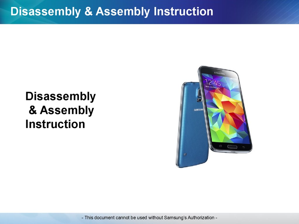
Disassembly & Assembly InstructionDisassembly
& Assembly
Instruction
- This document cannot be used without Samsung’s Authorization -
7.
Guide of disassembly- This document cannot be used without Samsung’s Authorization -
8.
Guide of disassemblyPre-requisite
Screw driver
Disassembly knife
Glass Absorber
Anti-static mat
Tweezers
Anti-static gloves
Ethyl Alcohol
Mobile Dryer
- This document cannot be used without Samsung’s Authorization -
9.
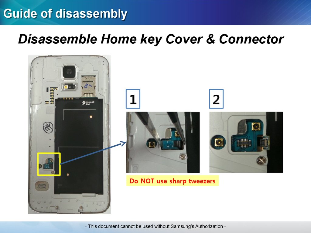
Guide of disassemblyDisassemble Home key Cover & Connector
1
2
Do NOT use sharp tweezers
- This document cannot be used without Samsung’s Authorization -
10.
Guide of disassemblyPut the device into the Dryer
Temperature: 80℃
Time: 10minutes
- This document cannot be used without Samsung’s Authorization -
11.
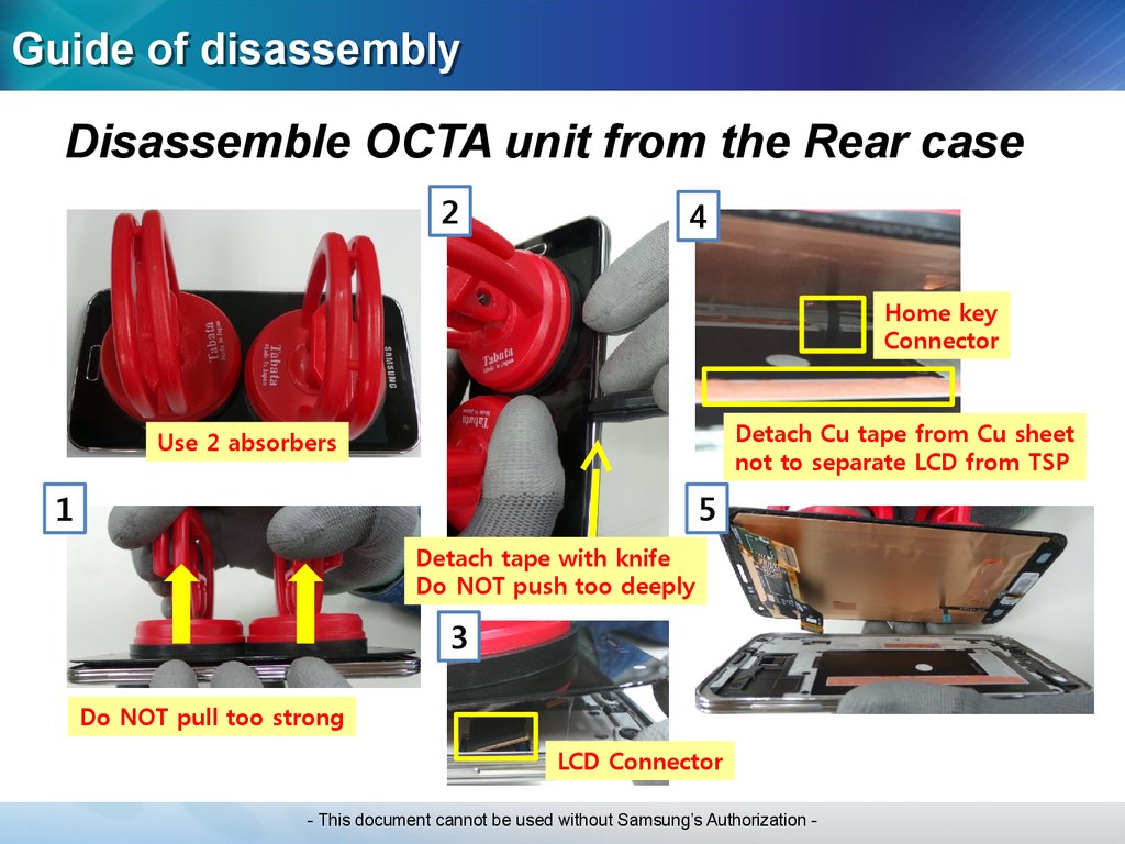
Guide of disassemblyDisassemble OCTA unit from the Rear case
2
4
Home key
Connector
Detach Cu tape from Cu sheet
not to separate LCD from TSP
Use 2 absorbers
1
5
Detach tape with knife
Do NOT push too deeply
3
Do NOT pull too strong
LCD Connector
- This document cannot be used without Samsung’s Authorization -
12.
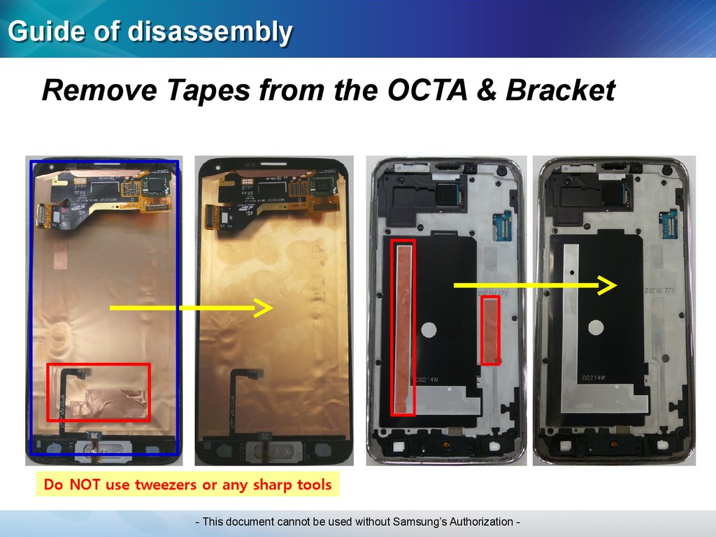
Guide of disassemblyRemove Tapes from the OCTA & Bracket
Do NOT use tweezers or any sharp tools
- This document cannot be used without Samsung’s Authorization -
13.
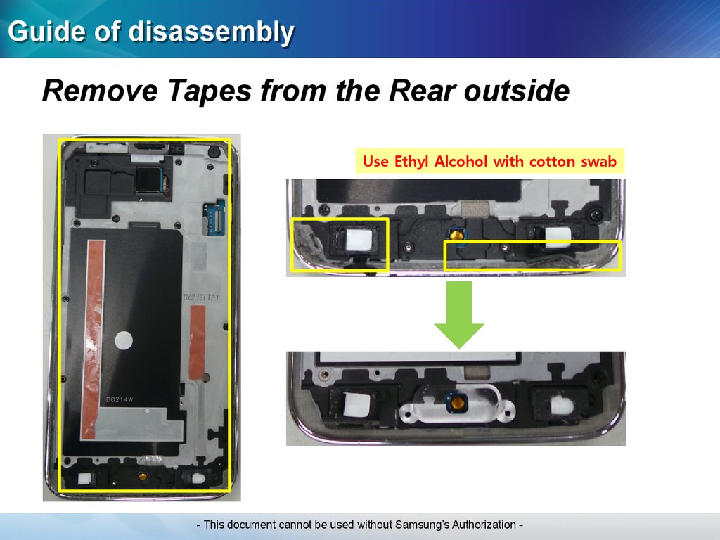
Guide of disassemblyRemove Tapes from the Rear outside
Use Ethyl Alcohol with cotton swab
- This document cannot be used without Samsung’s Authorization -
14.
Guide of disassemblyDisassemble Bracket from the Rear case
②
①
①
Total 13 points
Be careful not to bend bracket,
especially Battery plate
③
- This document cannot be used without Samsung’s Authorization -
15.
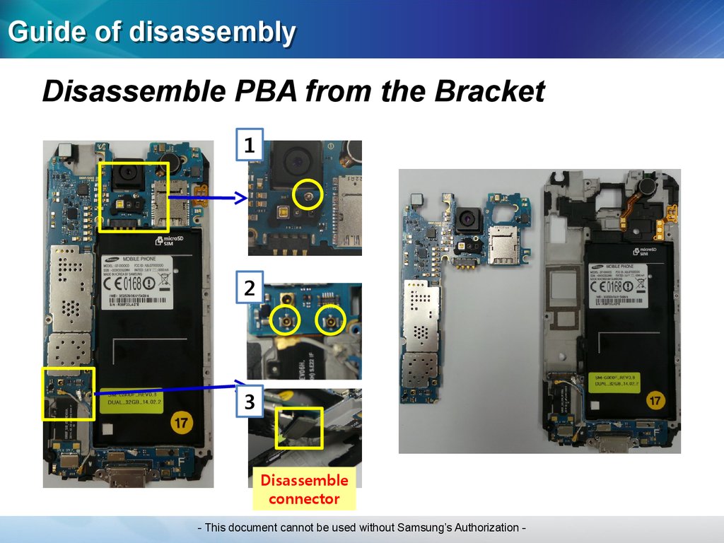
Guide of disassemblyDisassemble PBA from the Bracket
1
2
3
Disassemble
connector
- This document cannot be used without Samsung’s Authorization -
16.
Guide of disassemblyDisassemble Sub PBA from the Bracket
1
Work via disassembly hole
2
3
Detach with tweezers
via disassembly hole
- This document cannot be used without Samsung’s Authorization -
17.
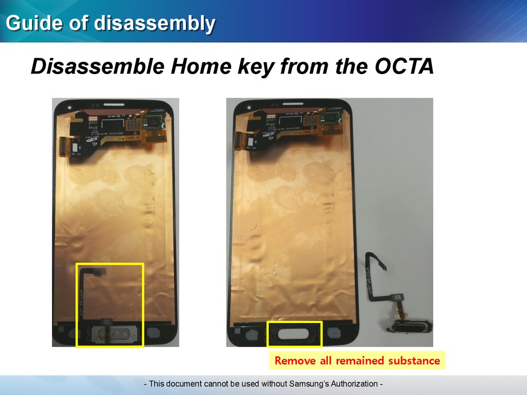
Guide of disassemblyDisassemble Home key from the OCTA
Remove all remained substance
- This document cannot be used without Samsung’s Authorization -
18.
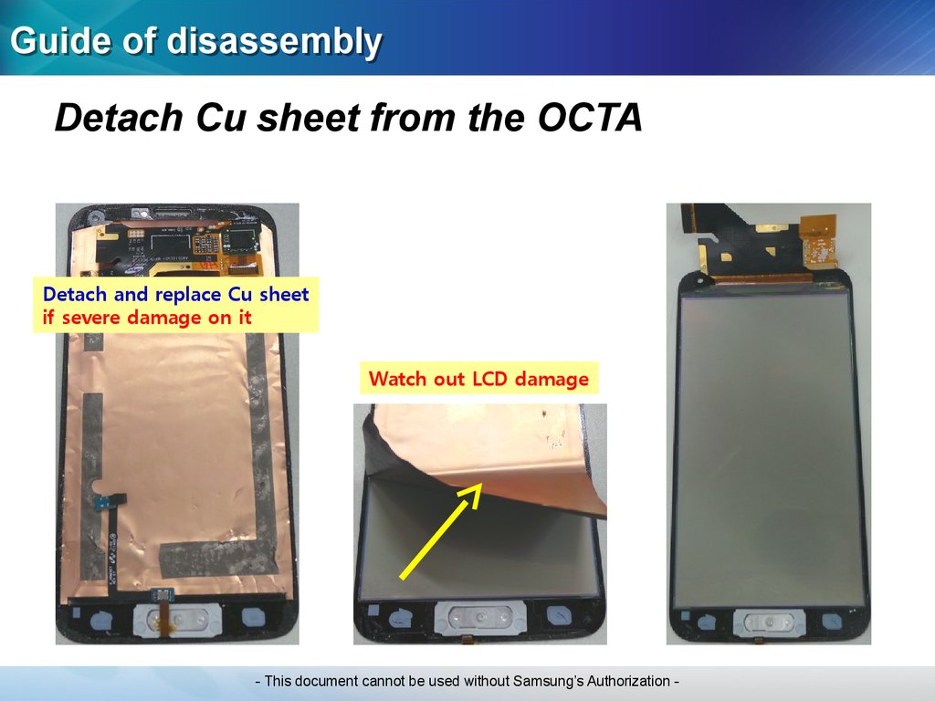
Guide of disassemblyDetach Cu sheet from the OCTA
Detach and replace Cu sheet
if severe damage on it
Watch out LCD damage
- This document cannot be used without Samsung’s Authorization -
19.
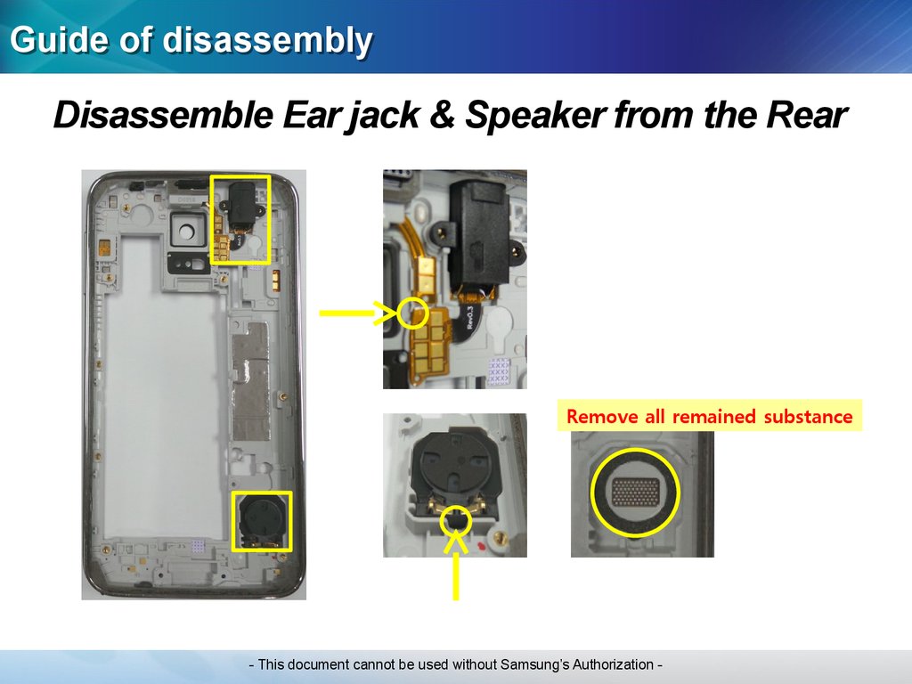
Guide of disassemblyDisassemble Ear jack & Speaker from the Rear
Remove all remained substance
- This document cannot be used without Samsung’s Authorization -
20.
Guide of disassemblyDisassemble Motor from the Bracket
- This document cannot be used without Samsung’s Authorization -
21.
Guide of assembly- This document cannot be used without Samsung’s Authorization -
22.
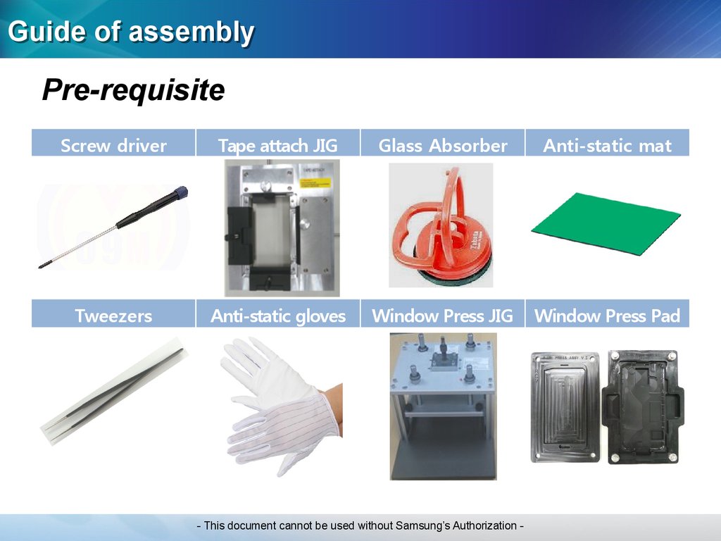
Guide of assemblyPre-requisite
Screw driver
Tape attach JIG
Glass Absorber
Anti-static mat
Tweezers
Anti-static gloves
Window Press JIG
Window Press Pad
- This document cannot be used without Samsung’s Authorization -
23.
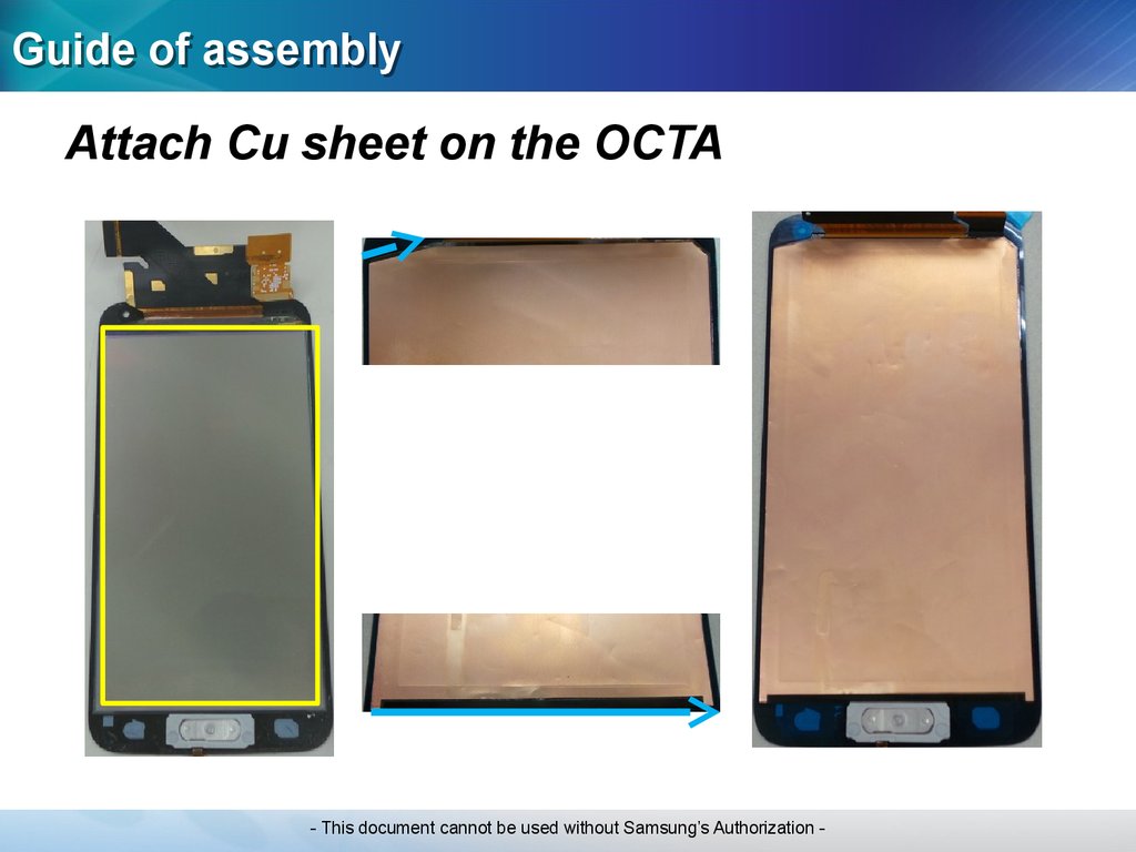
Guide of assemblyAttach Cu sheet on the OCTA
- This document cannot be used without Samsung’s Authorization -
24.
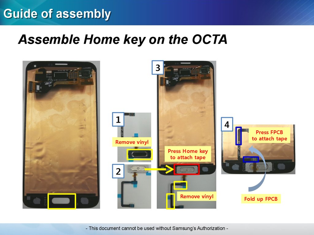
Guide of assemblyAssemble Home key on the OCTA
3
1
4
Remove vinyl
Press FPCB
to attach tape
Press Home key
to attach tape
2
Remove vinyl
- This document cannot be used without Samsung’s Authorization -
Fold up FPCB
25.
Guide of assemblyAssemble Ear jack & Speaker on the Rear
Join on the 1 guide point
Press Speaker enough
- This document cannot be used without Samsung’s Authorization -
26.
Guide of assemblyAssemble Motor on the Bracket
- This document cannot be used without Samsung’s Authorization -
27.
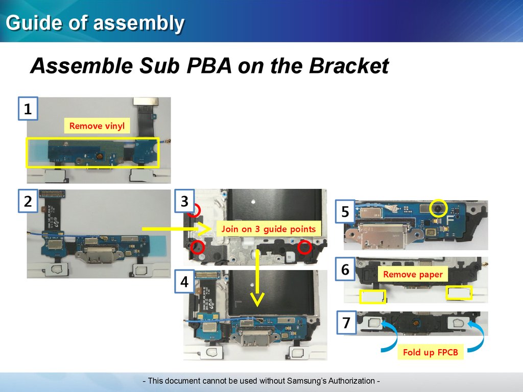
Guide of assemblyAssemble Sub PBA on the Bracket
1
Remove vinyl
2
3
5
Join on 3 guide points
4
6
Remove paper
7
Fold up FPCB
- This document cannot be used without Samsung’s Authorization -
28.
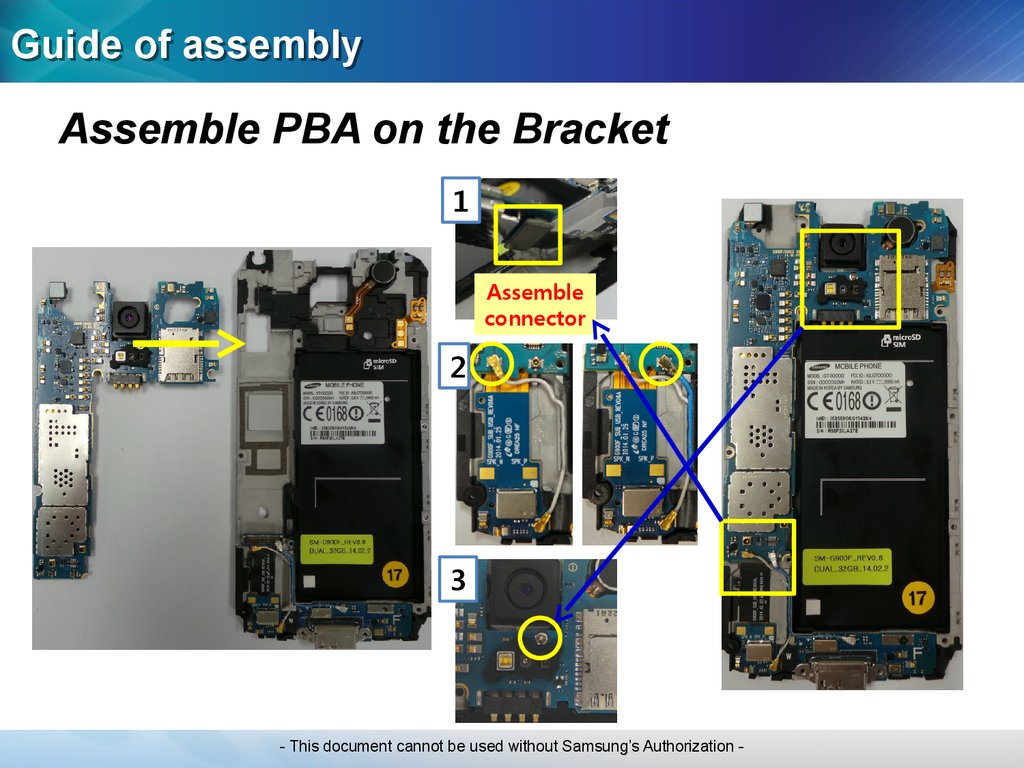
Guide of assemblyAssemble PBA on the Bracket
1
Assemble
connector
2
3
- This document cannot be used without Samsung’s Authorization -
29.
Guide of assemblyAssemble Bracket on the Rear case
③
②
②
Total 13 points
Do NOT push Battery plate
①
- This document cannot be used without Samsung’s Authorization -
30.
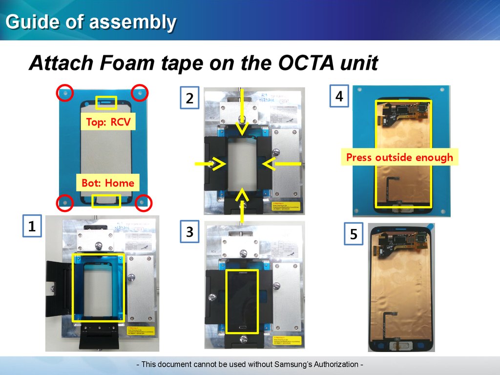
Guide of assemblyAttach Foam tape on the OCTA unit
2
4
Top: RCV
Press outside enough
Bot: Home
1
3
5
- This document cannot be used without Samsung’s Authorization -
31.
Guide of assemblyAttach Cu tape on the Bracket
- This document cannot be used without Samsung’s Authorization -
32.
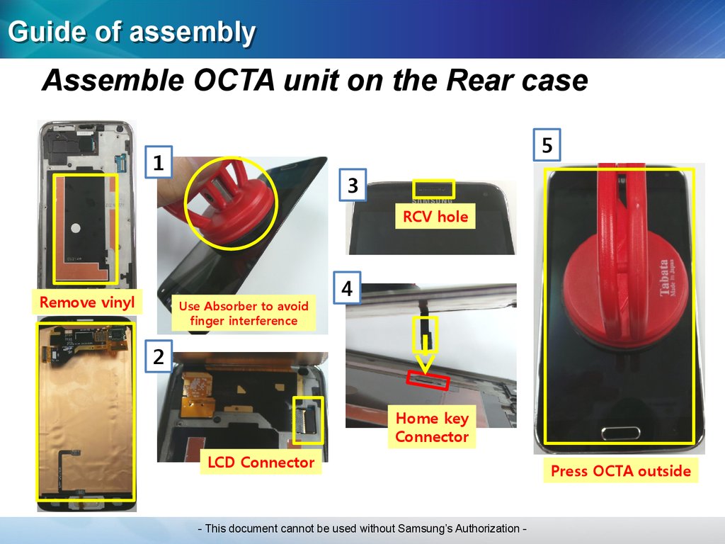
Guide of assemblyAssemble OCTA unit on the Rear case
5
1
3
RCV hole
Remove vinyl
Use Absorber to avoid
finger interference
4
2
Home key
Connector
LCD Connector
- This document cannot be used without Samsung’s Authorization -
Press OCTA outside
33.
Guide of assemblyConnect Home key and Assemble Cover
- This document cannot be used without Samsung’s Authorization -
34.
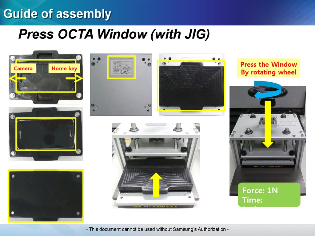
Guide of assemblyPress OCTA Window (with JIG)
Camera
Press the Window
By rotating wheel
Home key
Force: 1N
Time:
1minute
- This document cannot be used without Samsung’s Authorization -
35.
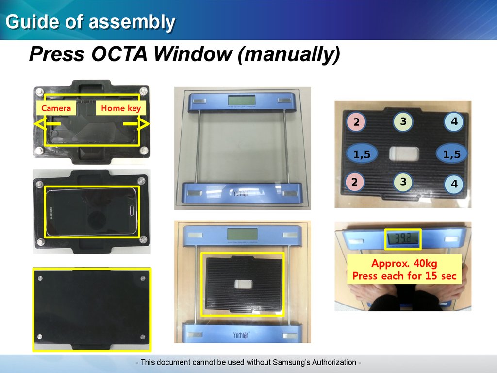
Guide of assemblyPress OCTA Window (manually)
Camera
Home key
2
3
1,5
2
4
1,5
3
4
Approx. 40kg
Press each for 15 sec
- This document cannot be used without Samsung’s Authorization -
36.
Electronic ComponentsElectronic
Components
- This document cannot be used without Samsung’s Authorization -
37.
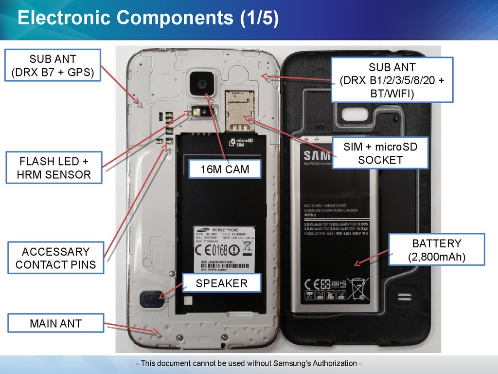
Electronic Components (1/5)SUB ANT
(DRX B7 + GPS)
FLASH LED +
HRM SENSOR
SUB ANT
(DRX B1/2/3/5/8/20 +
BT/WIFI)
16M CAM
SIM + microSD
SOCKET
BATTERY
(2,800mAh)
ACCESSARY
CONTACT PINS
SPEAKER
MAIN ANT
- This document cannot be used without Samsung’s Authorization -
38.
Electronic Components (2/5)2ND MIC HOLE
ANT CONTACT
ANT CONTACT
POWER KEY
VOLUME KEY
EAR-JACK
RECEIVER
IR LED
WINDOW
GRAPHITE
SHEET
SPEAKER
ANT CONTACT
MAIN MIC HOLE
- This document cannot be used without Samsung’s Authorization -
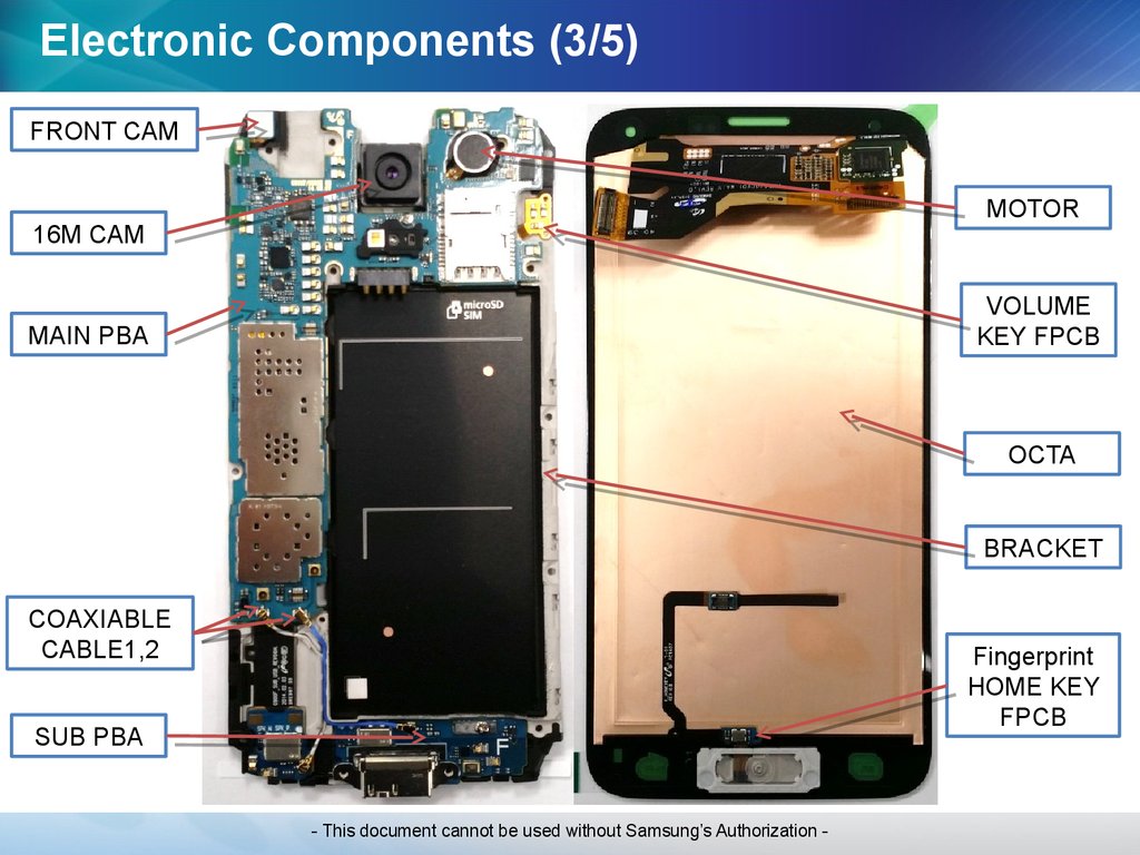
39.
Electronic Components (3/5)FRONT CAM
MOTOR
16M CAM
VOLUME
KEY FPCB
MAIN PBA
OCTA
BRACKET
COAXIABLE
CABLE1,2
Fingerprint
HOME KEY
FPCB
SUB PBA
- This document cannot be used without Samsung’s Authorization -
40.
Electronic Components (4/5)- This document cannot be used without Samsung’s Authorization -
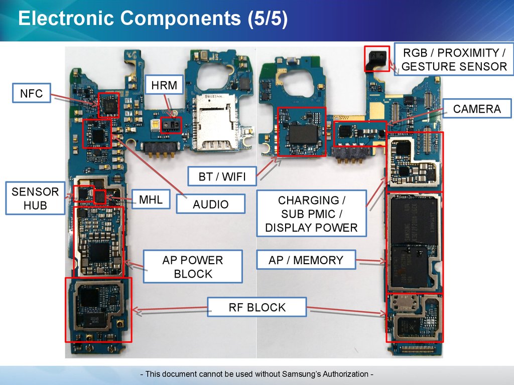
41.
Electronic Components (5/5)RGB / PROXIMITY /
GESTURE SENSOR
NFC
HRM
CAMERA
BT / WIFI
SENSOR
HUB
MHL
AUDIO
AP POWER
BLOCK
CHARGING /
SUB PMIC /
DISPLAY POWER
AP / MEMORY
RF BLOCK
- This document cannot be used without Samsung’s Authorization -
42.
SMD parts (TOP side)ANT400
Ant. Contact (for GPS)
MIC801
SUB MIC
ANT815/816
RCV Contact
ANT1101/1102
Ant. Contact (for Sub Ant.1)
U407
Magnetic Sensor
ANT401/402
Ant. Contact (for BT/WIFI)
U410
NFC
F1107
CRX MLB LNA
(BAND1/2/3/5/8/20)
ANT1100/1103
Ant. Contact (for Sub Ant.2)
ANT401/402
Ant. Contact (for BT/WIFI)
U804
Audio Codec
SIM600
SIM/SD CARD SOCKET
ANT806/807
Power key Contact
U400
HRM SENSOR
U7002
GPIO Expander
U406
6 Axis Sensor (GYRO,ACCEL)
U403
SENSOR Hub
U1001
MHL 2.0
LED7000
Flash LED
ANT403/404/7000/7001/7005
COVER Contact
U7003
PMIC
U302
Transceiver
U7004
FPGA
ANT808/811/812/813/814
Earjack Contact
BTC7000
Battery Connector
U105
SUB MLB SW
(BAND1/2/3/5/8/20)
F102
BAND1 PRX
U803
2-MIC CHIP
F101
MAIN FEMID
(BAND1TX/2/3/5/8/20)
U103
MAIN SWITCH
(BAND7/38/40/B1 PRX)
HDC400
BTP IF Conn
U901
OVP IC
- This document cannot be used without Samsung’s Authorization -
43.
SMD parts (Bottom side)LED1000
SVC LED
U1000
Gesture Sensor
IRDA1000
IRDA
U404
Barometer Sensor
U1104
RF Switch (BAND1/2/3)
HDC900
VT Camera Connector
U1109
RF Switch (BAND5/8/20)
HDC901
16M Camera Connector
ANT803/804/805
Volume key Contact
U903
DC/DC DDI_Core 1.5V
U405
BT/WIFI
HDC902
OCTA Connector
ANT800/801
Vibration Motor Contact
U900
OCTA DC-DC
U904
Companion IC
UCP500(upper part)
POP MEMORY
U7005
Ext.Buck for 16M Camera
UCP500(lower part)
Application
& Communication
Proccesor
U7000
IF PMIC
UME6000
eMMC MEMORY
U7006
SUB PMIC
PA201
BAND7 PAD (PA+DPX)
U301 (in Shieldcan)
PA PMIC
PA200
BAND1/2/3/5/8/20, GSM
QUAD MMMB PA
U907
Load Switch
U805
MAIN MIC Bias LDO
HDC903
SUB FPCB IF Connector
- This document cannot be used without Samsung’s Authorization -
44.
Trouble ShootingTrouble Shooting
- This document cannot be used without Samsung’s Authorization -
45.
Test ModeCheck the symptom
-> *#0*#
- This document cannot be used without Samsung’s Authorization -
46.
Power problemStep
Check point
1
Confirm the defect symptom
2
Check the power with a new battery
3
Check the PBA current with a power supply
(power supply voltage : 3.8 ~ 4.0V)
4
Check the voltage of U7000(C7030)
5
Check the voltage of PMIC output.
6
Check the frequency of OSC7000
Result value
Defect point
-
-
Solved
Battery
Not solved
Go to the next step
High current (over 1A)
Circuit short
No current (almost 0mA)
Go to the next step
C7030 = 3.8V
(same as power supply voltage)
Go to the next step
If not the correct value
IF PMIC (U7000)
C7023 = 1.8V
Go to the next step
If not the correct value
MAIN PMIC (U7003)
19.2MHz
Main chip (UCP500)
If not the correct value
X-TAL (OSC7000)
- This document cannot be used without Samsung’s Authorization -
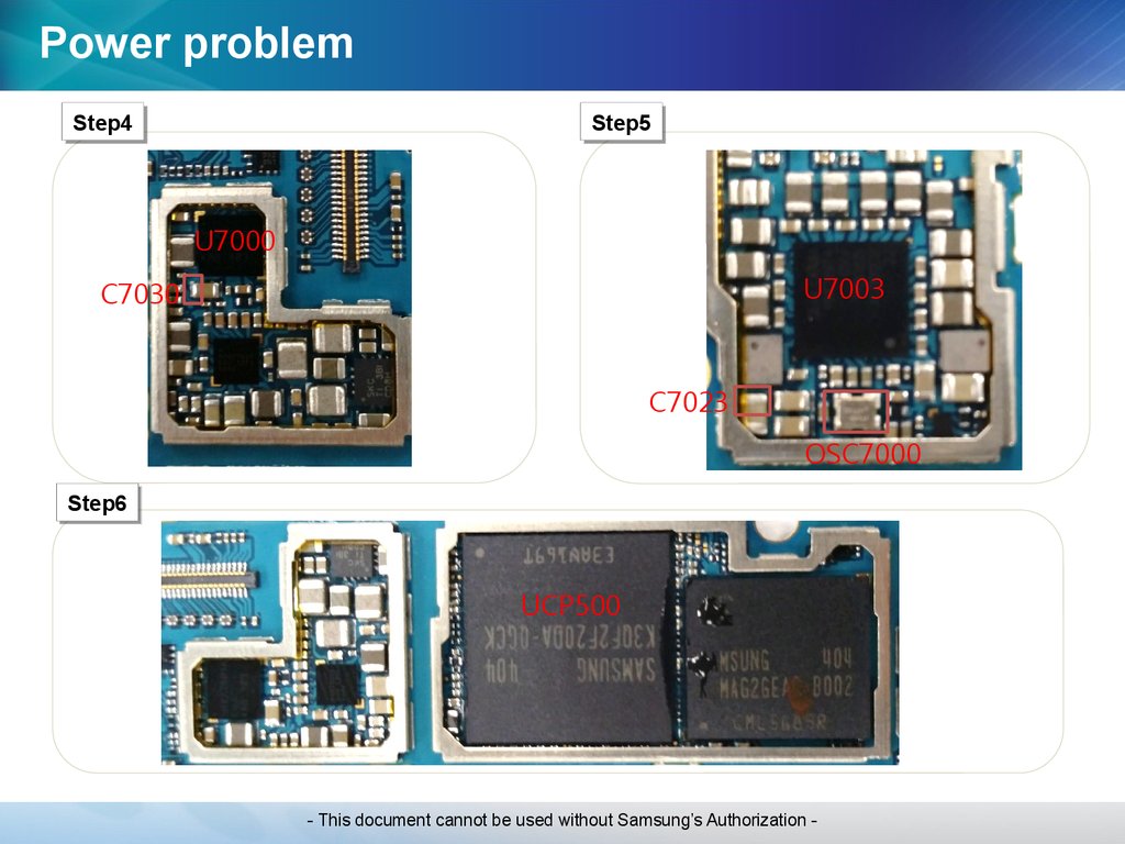
47.
Power problemStep4
Step4
Step5
Step5
U7000
U7003
C7030
C7023
OSC7000
Step6
Step6
UCP500
- This document cannot be used without Samsung’s Authorization -
48.
RF (GSM,WCDMA, LTE)Step
Check point
Result value
Defect point
-
-
Abnormal
Settings
Normal
Go to the next step
Broken, dust, corrosion
No insert
Coaxial cable
Main ant, diversity ant
Normal
Go to the next step
-
-
Check the status(crack, missing, Corrosion..etc)
of RF components.
Abnormal status
(compared with a good PBA)
RF components.
U302 Transceiver
F101 Main FEMID
PA200 PAM(Power Amplitude Module)
F1107 Sub FEM
U301 PA DCDC
Normal status
(compared with a good PBA)
CP(Call Processor)
(UCP500)
CP PMIC(U7003)
1
Confirm the defect symptom
(Make a call, check the debug screen *#0011# )
2
Check the settings
(airplane mode, Mobile networks)
3
4
5
Check the status coaxial cable & main ANT &
diversity ant.
Power on with a power supply
(power supply voltage : 3.8V)
- This document cannot be used without Samsung’s Authorization -
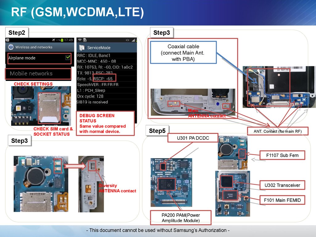
49.
RF (GSM,WCDMA,LTE)Step2
Step2
Step3
Step3
Coaxial cable
(connect Main Ant.
with PBA)
CHECK SETTINGS
CHECK SIM card &
SOCKET STATUS
DEBUG SCREEN
STATUS
Same value compared
with normal device.
Main
ANTENNA contact
Step5
Step5
ANT. Contact (for main RF)
U301 PA DCDC
Step3
Step3
F1107 Sub Fem
U302 Transceiver
Diversity
ANTENNA contact
F101 Main FEMID
PA200 PAM(Power
Amplitude Module)
- This document cannot be used without Samsung’s Authorization -
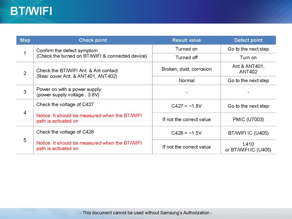
50.
BT/WIFIStep
Check point
Result value
Defect point
1
Confirm the defect symptom
(Check the turned on BT/WIFI & connected device)
Turned on
Go to the next step
Turned off
Turn on
2
Check the BT/WIFI Ant. & Ant contact.
(Rear cover Ant. & ANT401, ANT402)
Broken, dust, corrosion
Ant & ANT401,
ANT402
Normal
Go to the next step
-
-
C427 = ~1.8V
Go to the next step
If not the correct value
PMIC (U7003)
C428 = ~1.5V
BT/WIFI IC (U405)
If not the correct value
L410
or BT/WIFI IC (U405)
3
Power on with a power supply
(power supply voltage : 3.8V)
Check the voltage of C427
4
Notice. It should be measured when the BT/WIFI
path is activated on
Check the voltage of C428
5
Notice. It should be measured when the BT/WIFI
path is activated on
- This document cannot be used without Samsung’s Authorization -
51.
BT/WIFIStep1
Step1
Step2
Step2
BT/ WIFI ANTENNA
CONTACT
ANT402
BT/ WIFI ANTENNA
(LDS TYPE)
WIFI 2nd ANTENNA
(LDS TYPE)
WIFI 2nd ANTENNA
CONTACT
Step4
Step4 &
& 55
BT/ WIFI IC
L410
C427
C428
U7003 (PMIC)
- This document cannot be used without Samsung’s Authorization -
ANT401
52.
NFCStep
Check point
1
Confirm the defect symptom
(Check the turned on NFC function)
2
Check the status of BATTERY
(NFC Antenna is in BATTERY)
3
Power on with a power supply
(power supply voltage : 3.8V)
Check the voltage of R419
4
Notice. It should be measured when the NFC path
is activated on
Check the clock of R7004
5
Notice. It should be measured when the NFC path
is activated on
Result value
Defect point
Turned on
Go to the next step
Turned off
Turn on
Broken, dust, corrosion,
wrong
BATTERY
Normal
Go to the next step
-
-
R419=1.8V
Go to the next step
If not the correct value
PMIC (U7003)
R7004 = 19.2Mhz
(Same signal compared with
a good PBA)
MAIN CHIP(UCP500)
or NFC Chip(U410)
If not the correct value
PMIC (U7003)
or OSC7000
- This document cannot be used without Samsung’s Authorization -
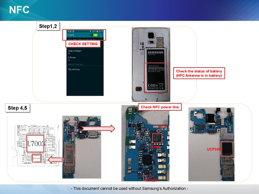
53.
NFCStep1,2
Step1,2
CHECK SETTING
Check the status of battery
(NFC Antenna is in battery)
Step
Step 4,5
4,5
Check NFC power line
R419
U401
R7004
- This document cannot be used without Samsung’s Authorization -
UCP500
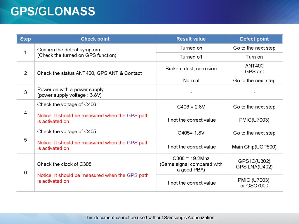
54.
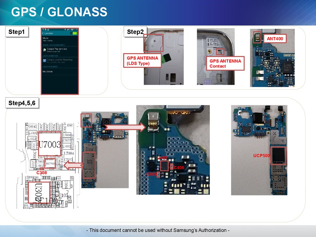
GPS/GLONASSStep
1
2
3
Check point
Confirm the defect symptom
(Check the turned on GPS function)
Check the status ANT400, GPS ANT & Contact
Power on with a power supply
(power supply voltage : 3.8V)
Check the voltage of C406
4
Notice. It should be measured when the GPS path
is activated on
Check the voltage of C405
5
Notice. It should be measured when the GPS path
is activated on
Check the clock of C308
6
Notice. It should be measured when the GPS path
is activated on
Result value
Defect point
Turned on
Go to the next step
Turned off
Turn on
Broken, dust, corrosion
ANT400
GPS ant
Normal
Go to the next step
-
-
C406 = 2.8V
Go to the next step
If not the correct value
PMIC(U7003)
C405= 1.8V
Go to the next step
If not the correct value
Main Chip(UCP500)
C308 = 19.2Mhz
(Same signal compared with
a good PBA)
GPS IC(U302)
GPS LNA(U402)
If not the correct value
PMIC (U7003)
or OSC7000
- This document cannot be used without Samsung’s Authorization -
55.
GPS / GLONASSStep1
Step1
Step2
Step2
ANT400
GPS ANTENNA
(LDS Type)
GPS ANTENNA
Contact
Step4,5,6
Step4,5,6
UCP500
U402
C406
C308
C405
- This document cannot be used without Samsung’s Authorization -
56.
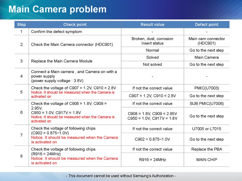
Main Camera problemStep
1
2
Check point
Confirm the defect symptom
Check the Main Camera connector (HDC901)
Result value
Defect point
-
-
Broken, dust, corrosion
Insert status
Main cam connector
(HDC901)
Normal
Go to the next step
Solved
Main Camera
Not solved
Go to the next step
3
Replace the Main Camera Module
4
Connect a Main camera , and Camera on with a
power supply
(power supply voltage : 3.8V)
-
-
Check the voltage of C907 = 1.2V, C910 = 2.8V
If not the correct value
PMIC(U7003)
Notice. It should be measured when the Camera is
activated on
C907 = 1.2V, C910 = 2.8V
Go to the next step
If not the correct value
SUB PMIC(U7006)
C908 = 1.8V, C909 = 2.95V
C950 = 1.0V, C917V = 1.8V
Go to the next step
If not the correct value
U7005 or L7015
7
Check the voltage of following chips
(C902 = 0.875~1.0V)
Notice. It should be measured when the Camera
is activated on
C902 = 0.875~1.0V
Go to the next step
If not the correct value
Replace the PBA
8
Check the voltage of following chips
(R916 = 24MHz)
Notice. It should be measured when the Camera
is activated on
R916 = 24MHz
MAIN CHIP
5
6
Check the voltage of C908 = 1.8V, C909 =
2.95V,
C950 = 1.0V, C917V = 1.8V
Notice. It should be measured when the Camera is
activated on
- This document cannot be used without Samsung’s Authorization -
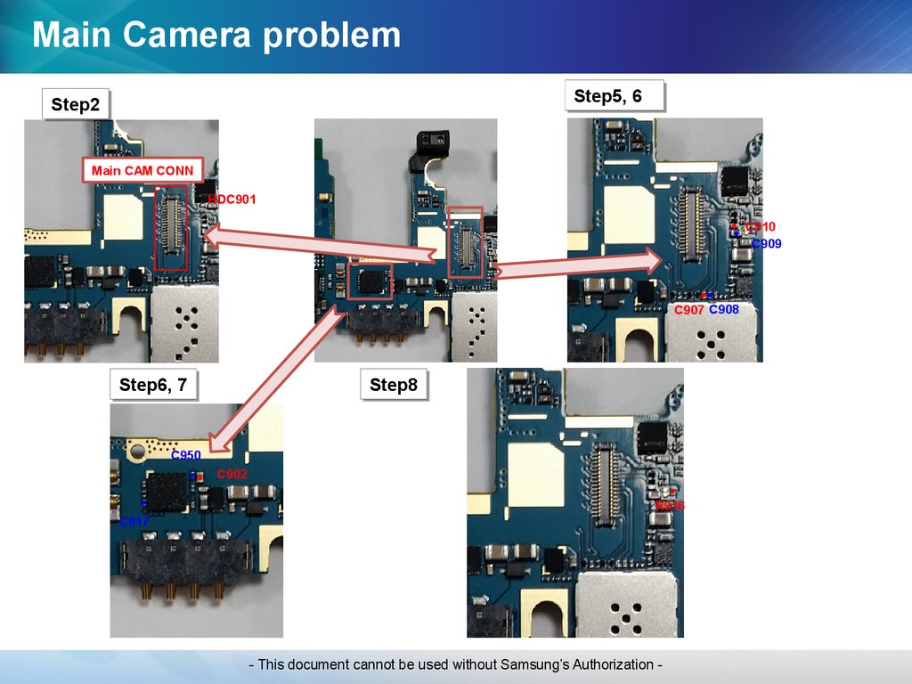
57.
Main Camera problemStep5,
Step5, 66
Step2
Step2
Main CAM CONN
HDC901
C910
C909
C907 C908
Step8
Step8
Step6,
Step6, 77
C950
C902
R916
C917
- This document cannot be used without Samsung’s Authorization -
58.
Display problemStep
1
2
Check point
Confirm the defect symptom
Check the AMOLED connector (HDC902)
3
Replace the AMOLED
4
Connect a AMOLED, and display on with a
power supply
(power supply voltage : 4.0V)
5
6
7
Check the voltage of C906 = 3.0V
Notice. It should be measured when the display is
activated on
Check the voltage of C921 = 1.5V
Notice. It should be measured when the display is
activated on
Check the voltage of following chips
(C903,C919,C920)
Notice. It should be measured when the display
is activated on
Result value
Defect point
-
-
Broken, dust, corrosion
Insert status
AMOLED connector
(HDC902)
Normal
Go to the next step
Solved
AMOLED
Not solved
Go to the next step
-
-
If not the correct value
PMIC(U7003)
C906=3.0V
Go to the next step
If not the correct value
U903
C921=1.5V
Go to the next step
If not the correct value
U900
C903 = 7.0V
C919 = -1.4 ~ -4.4V
C920 = 4.6V
MAIN CHIP
- This document cannot be used without Samsung’s Authorization -
59.
Display problemStep5,
Step5, 66
Step2
Step2
LCD CONNECTOR
HDC902
C906
U900
C921
Step7
Step7
C903
C919
C920
- This document cannot be used without Samsung’s Authorization -
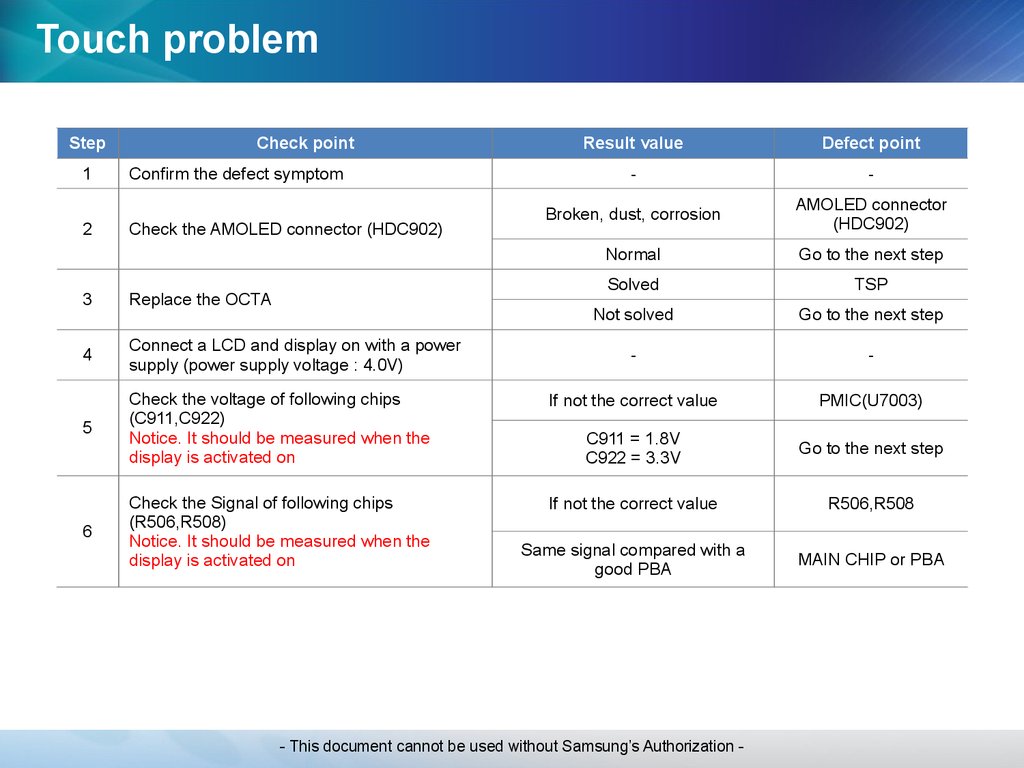
60.
Touch problemStep
1
2
Check point
Confirm the defect symptom
Check the AMOLED connector (HDC902)
Result value
Defect point
-
-
Broken, dust, corrosion
AMOLED connector
(HDC902)
Normal
Go to the next step
Solved
TSP
Not solved
Go to the next step
-
-
3
Replace the OCTA
4
Connect a LCD and display on with a power
supply (power supply voltage : 4.0V)
If not the correct value
PMIC(U7003)
5
Check the voltage of following chips
(C911,C922)
Notice. It should be measured when the
display is activated on
C911 = 1.8V
C922 = 3.3V
Go to the next step
Check the Signal of following chips
(R506,R508)
Notice. It should be measured when the
display is activated on
If not the correct value
R506,R508
Same signal compared with a
good PBA
MAIN CHIP or PBA
6
- This document cannot be used without Samsung’s Authorization -
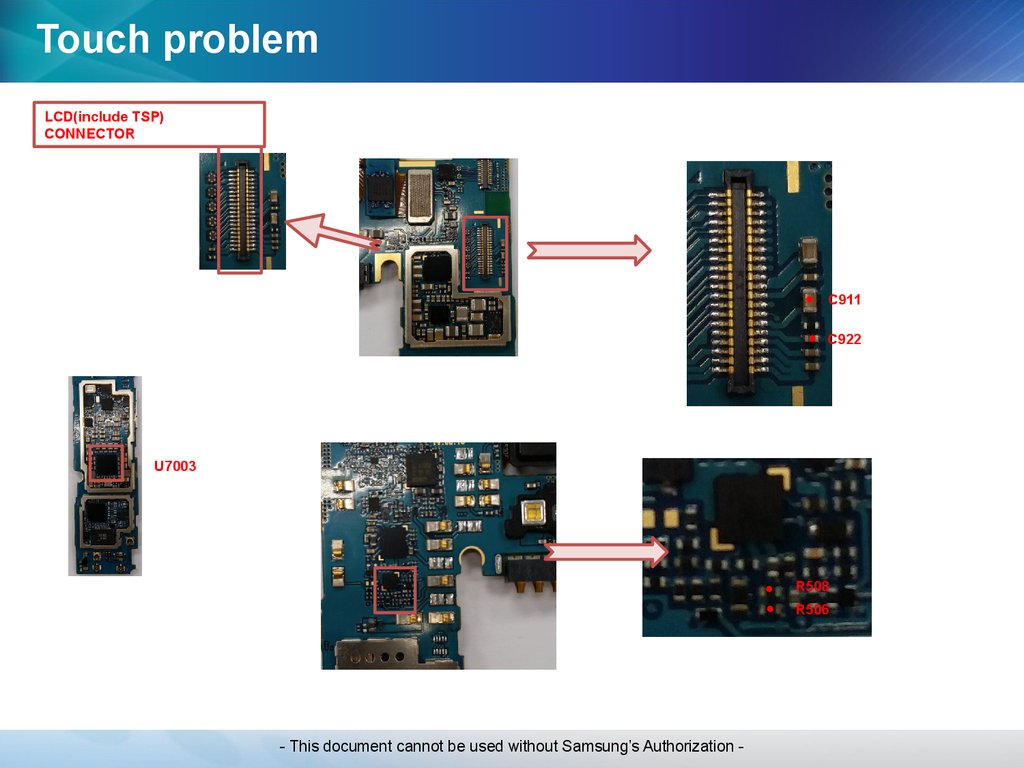
61.
Touch problemLCD(include TSP)
CONNECTOR
C911
C922
U7003
R508
R506
- This document cannot be used without Samsung’s Authorization -
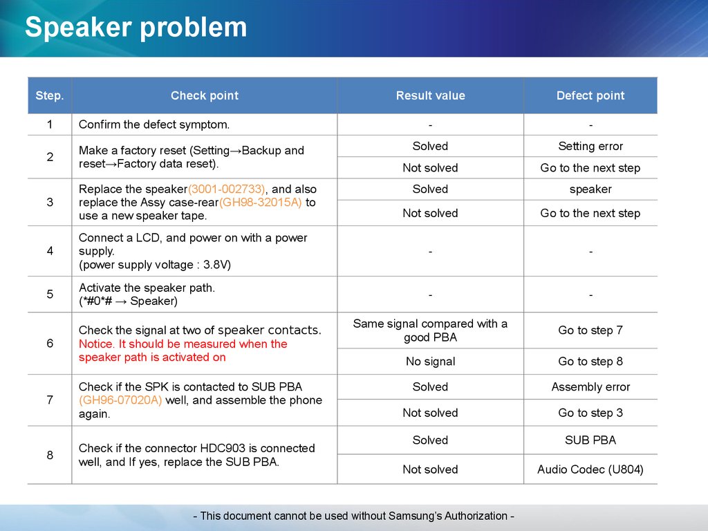
62.
Speaker problemStep.
Check point
Result value
Defect point
-
-
Solved
Setting error
Not solved
Go to the next step
Solved
speaker
Not solved
Go to the next step
1
Confirm the defect symptom.
2
Make a factory reset (Setting→Backup and
reset→Factory data reset).
3
Replace the speaker(3001-002733), and also
replace the Assy case-rear(GH98-32015A) to
use a new speaker tape.
4
Connect a LCD, and power on with a power
supply.
(power supply voltage : 3.8V)
-
-
5
Activate the speaker path.
(*#0*# → Speaker)
-
-
6
Check the signal at two of speaker contacts.
Notice. It should be measured when the
speaker path is activated on
Same signal compared with a
good PBA
Go to step 7
No signal
Go to step 8
Solved
Assembly error
Not solved
Go to step 3
Solved
SUB PBA
Not solved
Audio Codec (U804)
7
Check if the SPK is contacted to SUB PBA
(GH96-07020A) well, and assemble the phone
again.
8
Check if the connector HDC903 is connected
well, and If yes, replace the SUB PBA.
- This document cannot be used without Samsung’s Authorization -
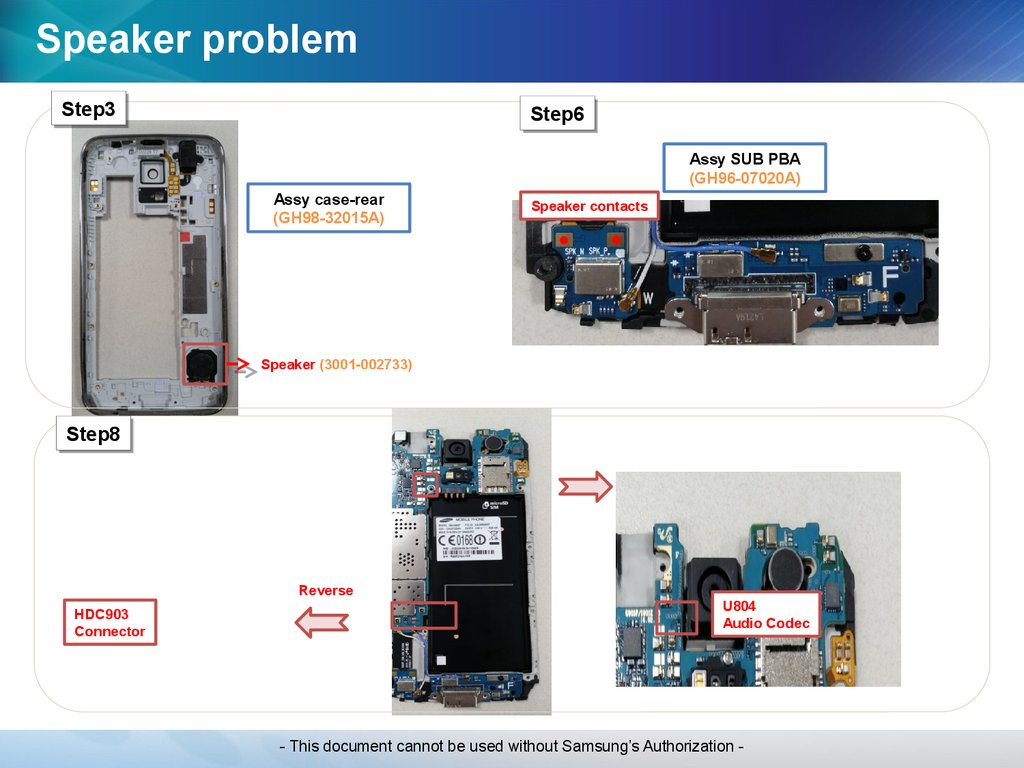
63.
Speaker problemStep3
Step3
Step6
Step6
Assy SUB PBA
(GH96-07020A)
Assy case-rear
(GH98-32015A)
Speaker contacts
Speaker (3001-002733)
Step8
Step8
Reverse
HDC903
Connector
U804
Audio Codec
- This document cannot be used without Samsung’s Authorization -
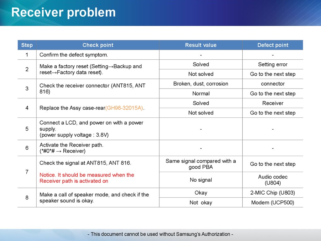
64.
Receiver problemStep
Check point
Result value
Defect point
-
-
Solved
Setting error
Not solved
Go to the next step
Broken, dust, corrosion
connector
Normal
Go to the next step
Solved
Receiver
Not solved
Go to the next step
1
Confirm the defect symptom.
2
Make a factory reset (Setting→Backup and
reset→Factory data reset).
3
Check the receiver connector (ANT815, ANT
816)
4
Replace the Assy case-rear(GH98-32015A).
5
Connect a LCD, and power on with a power
supply.
(power supply voltage : 3.8V)
-
-
6
Activate the Receiver path.
(*#0*# → Receiver)
-
-
Check the signal at ANT815, ANT 816.
Same signal compared with a
good PBA
Go to the next step
Notice. It should be measured when the
Receiver path is activated on
No signal
Audio codec
(U804)
Okay
2-MIC Chip (U803)
Not okay
Modem (UCP500)
7
8
Make a call of speaker mode, and check if the
speaker sound is okay.
- This document cannot be used without Samsung’s Authorization -
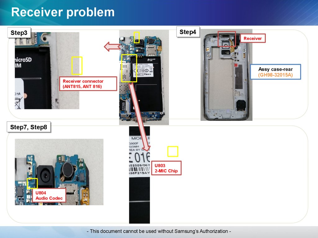
65.
Receiver problemStep4
Step4
Step3
Step3
Receiver
Assy case-rear
(GH98-32015A)
Receiver connector
(ANT815, ANT 816)
Step7,
Step7, Step8
Step8
U803
2-MIC Chip
U804
Audio Codec
- This document cannot be used without Samsung’s Authorization -
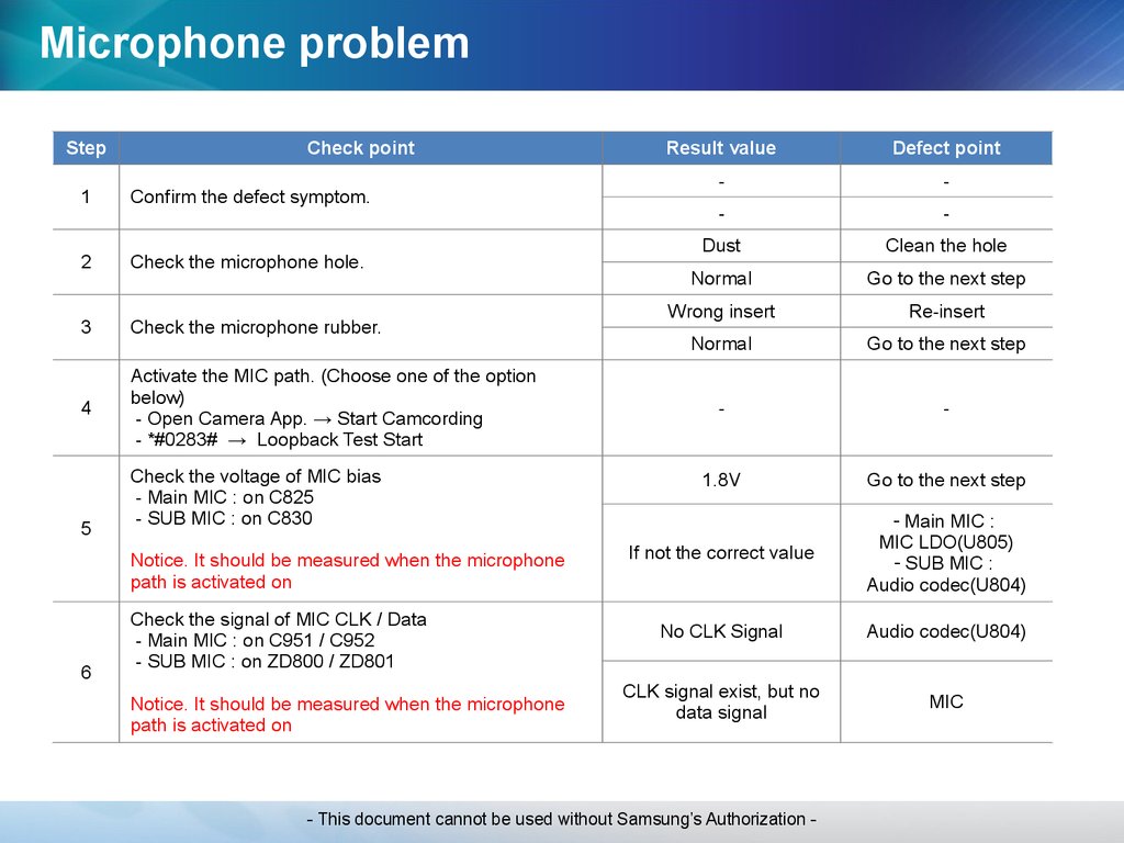
66.
Microphone problemStep
Check point
1
Confirm the defect symptom.
2
Check the microphone hole.
3
Check the microphone rubber.
4
Activate the MIC path. (Choose one of the option
below)
- Open Camera App. → Start Camcording
- *#0283# → Loopback Test Start
5
Check the voltage of MIC bias
- Main MIC : on C825
- SUB MIC : on C830
Notice. It should be measured when the microphone
path is activated on
6
Check the signal of MIC CLK / Data
- Main MIC : on C951 / C952
- SUB MIC : on ZD800 / ZD801
Notice. It should be measured when the microphone
path is activated on
Result value
Defect point
-
-
-
-
Dust
Clean the hole
Normal
Go to the next step
Wrong insert
Re-insert
Normal
Go to the next step
-
-
1.8V
Go to the next step
If not the correct value
- Main MIC :
MIC LDO(U805)
- SUB MIC :
Audio codec(U804)
No CLK Signal
Audio codec(U804)
CLK signal exist, but no
data signal
MIC
- This document cannot be used without Samsung’s Authorization -
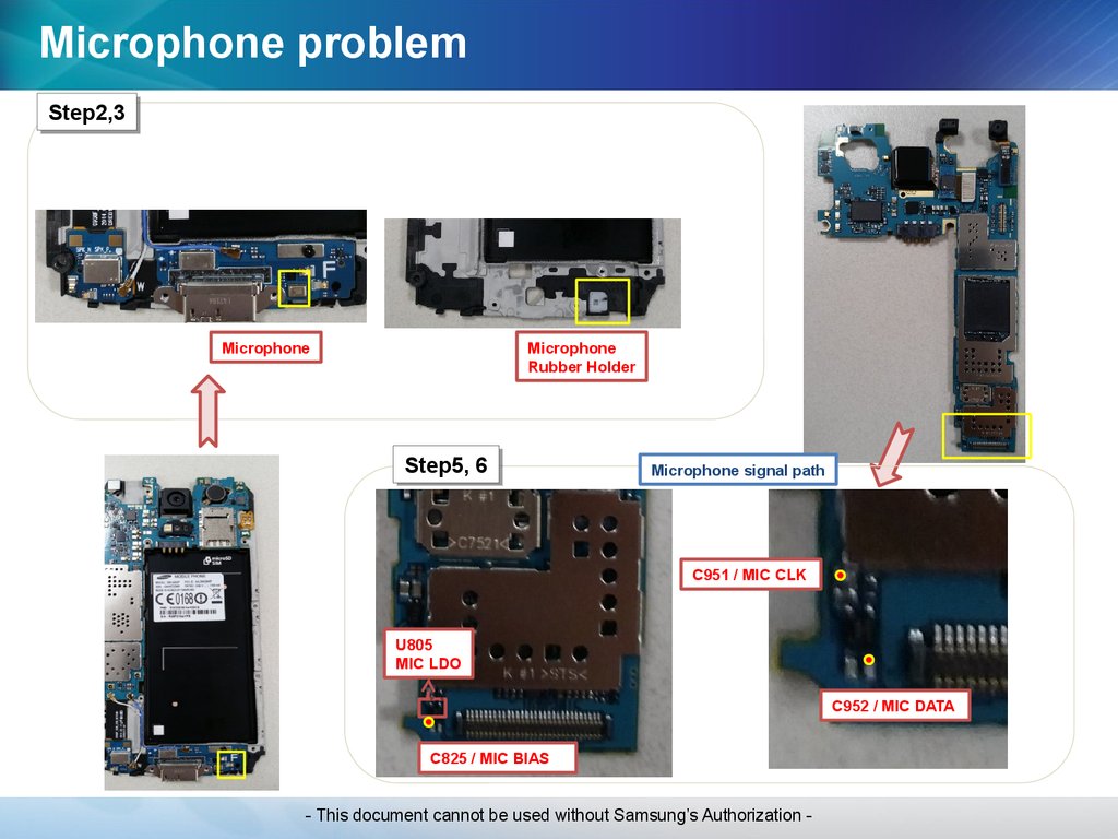
67.
Microphone problemStep2,3
Step2,3
Microphone
Microphone
Rubber Holder
Step5,
Step5, 66
Microphone signal path
C951 / MIC CLK
U805
MIC LDO
C952 / MIC DATA
C825 / MIC BIAS
- This document cannot be used without Samsung’s Authorization -
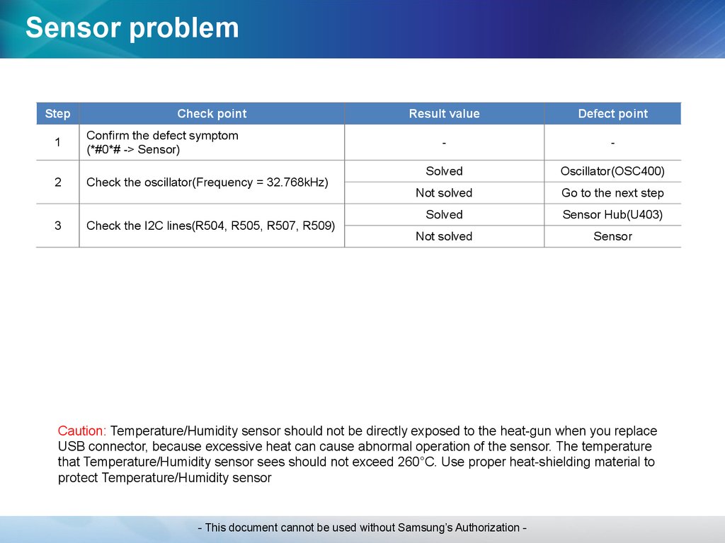
68.
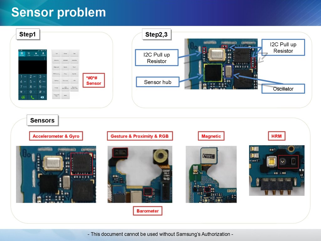
Sensor problemStep
Check point
1
Confirm the defect symptom
(*#0*# -> Sensor)
2
Check the oscillator(Frequency = 32.768kHz)
3
Check the I2C lines(R504, R505, R507, R509)
Result value
Defect point
-
-
Solved
Oscillator(OSC400)
Not solved
Go to the next step
Solved
Sensor Hub(U403)
Not solved
Sensor
Caution: Temperature/Humidity sensor should not be directly exposed to the heat-gun when you replace
USB connector, because excessive heat can cause abnormal operation of the sensor. The temperature
that Temperature/Humidity sensor sees should not exceed 260°C. Use proper heat-shielding material to
protect Temperature/Humidity sensor
- This document cannot be used without Samsung’s Authorization -
69.
Sensor problemStep1
Step1
Step2,3
Step2,3
I2C Pull up
Resistor
I2C Pull up
Resistor
*#0*#
Sensor
Sensor hub
Oscillator
Sensors
Sensors
Accelerometer & Gyro
Gesture & Proximity & RGB
Magnetic
Barometer
- This document cannot be used without Samsung’s Authorization -
HRM
70.
RF Calibration & S/W DownloadRF Calibration
S/W Download
- This document cannot be used without Samsung’s Authorization -
71.
CMW500 RF CAL SETUP (SM-G900F, LTE)Power Divider
50ohm Termination
RF CABLE
(1 for PRX, 1 for DRX)
- This document cannot be used without Samsung’s Authorization -
72.
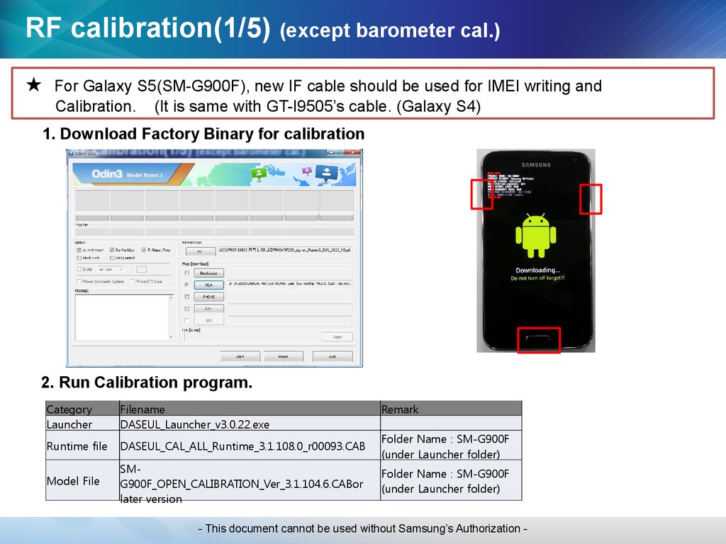
RF calibration(1/5) (except barometer cal.)★
For Galaxy S5(SM-G900F), new IF cable should be used for IMEI writing and
Calibration. (It is same with GT-I9505’s cable. (Galaxy S4)
1. Download Factory Binary for calibration
2. Run Calibration program.
Category
Launcher
Filename
DASEUL_Launcher_v3.0.22.exe
Runtime file
DASEUL_CAL_ALL_Runtime_3.1.108.0_r00093.CAB
Model File
SMG900F_OPEN_CALIBRATION_Ver_3.1.104.6.CABor
later version
Remark
Folder Name : SM-G900F
(under Launcher folder)
Folder Name : SM-G900F
(under Launcher folder)
- This document cannot be used without Samsung’s Authorization -
73.
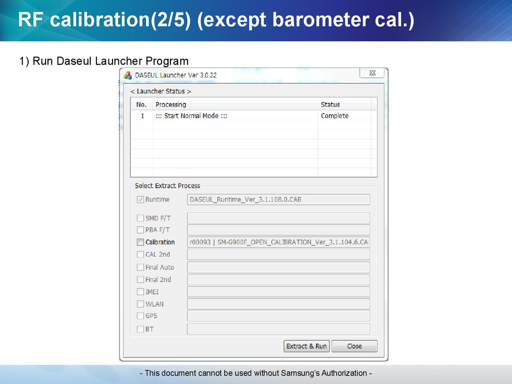
RF calibration(2/5) (except barometer cal.)1) Run Daseul Launcher Program
- This document cannot be used without Samsung’s Authorization -
74.
RF calibration(3/5) (except barometer cal.)2) Select Sequence Files and click Start.
3) Check ‘Calibration’
- This document cannot be used without Samsung’s Authorization -
75.
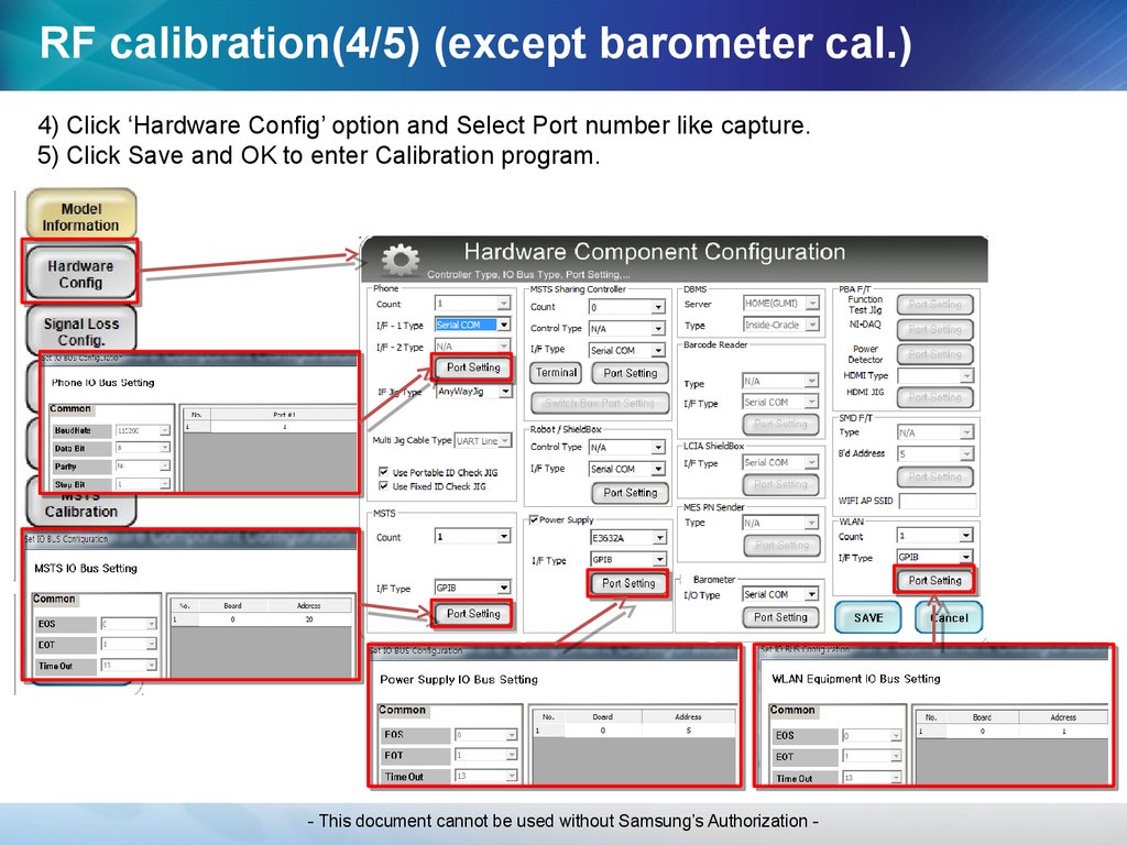
RF calibration(4/5) (except barometer cal.)4) Click ‘Hardware Config’ option and Select Port number like capture.
5) Click Save and OK to enter Calibration program.
- This document cannot be used without Samsung’s Authorization -
76.
RF calibration(5/5) (except barometer cal.)6) Click ‘START’ button and check if “Running” message appears.
- This document cannot be used without Samsung’s Authorization -
77.
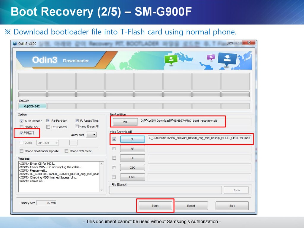
USER Binary Download1. Run the “Odin3 v3.09.exe
2. Open SW files (PIT, BL, AP, CP, CSC)
3. Enter into Download mode.
- press volume-down + Home + Power key simultaneously.
- press volume-up key when the warning screen comes up.
4. Connect the phone to PC using USB cable.
5. Click Start button when the phone is attached to PC.
- This document cannot be used without Samsung’s Authorization -
78.
Boot Recovery (1/5) – SM-G900F- Brief Process of Boot Recovery
1) Make T-Flash card for boot recovery.
2) Turn on the defective phone with T-Flash card inserted.
3) Download full S/W when the defective phone enters download mode automatically.
- Preparations
1) One normal SM-G900F phone
2) One micro-SD CARD (4GB↑)
3) Odin3 v3.09.exe
4) MSM8974PRO_boot_recovery.pit
5) Bootloader.tar.md5
- This document cannot be used without Samsung’s Authorization -
79.
Boot Recovery (2/5) – SM-G900F※ Download bootloader file into T-Flash card using normal phone.
- This document cannot be used without Samsung’s Authorization -
80.
Boot Recovery (3/5) – SM-G900F※ Screen of downloading with T-Flash card
- This document cannot be used without Samsung’s Authorization -
81.
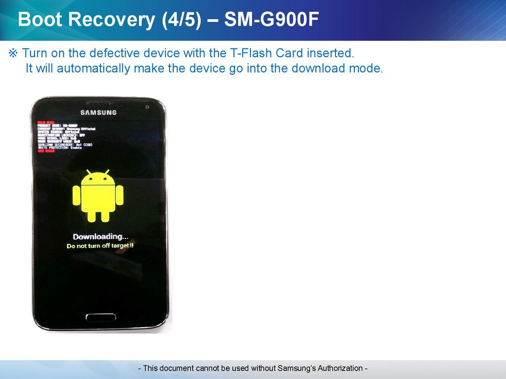
Boot Recovery (4/5) – SM-G900F※ Turn on the defective device with the T-Flash Card inserted.
It will automatically make the device go into the download mode.
- This document cannot be used without Samsung’s Authorization -
82.
Boot Recovery (5/5) – SM-G900F※ Download full S/W.
- This document cannot be used without Samsung’s Authorization -
83.
Q&AQuestion
- This document cannot be used without Samsung’s Authorization -