


 electronics
Similar presentations:


 Image Formation Processing")


Weather radar system
1.
WEATHER RADAR SYSTEMPurpose
The weather radar (WXR) system supplies these visual
indications:
Weather conditions
Windshear events
Land contours.
2.
DescriptionWXR operates on the same principle as an echo. The WXR
system transmits radio frequency (RF) pulses in a 180
degree area forward of the airplane. Objects reflect the
pulses back to the receiver. The receiver processes the
return signal to show weather, terrain, and windshear
events.
Display
The WXR returns show in four different colors on the
navigation displays (ND). Colors of the indications give the
crew information about the intensity of the returns.
3.
4.
5.
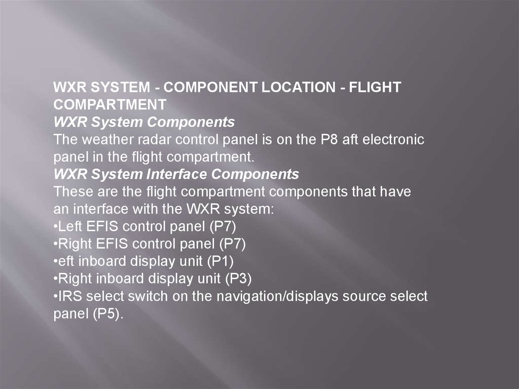
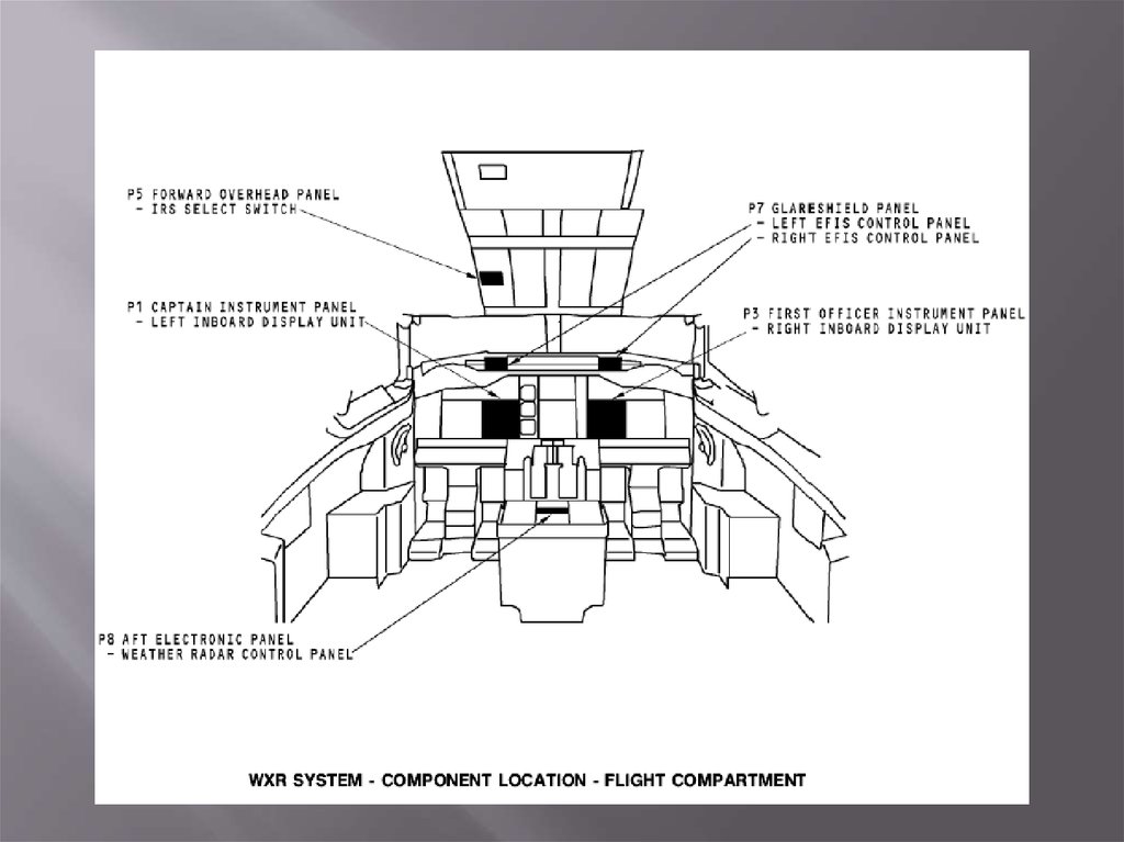
WXR SYSTEM - COMPONENT LOCATION - FLIGHTCOMPARTMENT
WXR System Components
The weather radar control panel is on the P8 aft electronic
panel in the flight compartment.
WXR System Interface Components
These are the flight compartment components that have
an interface with the WXR system:
•Left EFIS control panel (P7)
•Right EFIS control panel (P7)
•eft inboard display unit (P1)
•Right inboard display unit (P3)
•IRS select switch on the navigation/displays source select
panel (P5).
6.
7.
WXR SYSTEM - POWER AND ANALOG INTERFACESSystem Power and ON/OFF
The WXR receiver transmitter (R/T) gets 115v ac through the WXR RT circuit
breaker from the 115v ac XFR BUS 2 (P6 circuit breaker panel). The WXR
R/T circuit breaker also sends 115v ac to the WXR R/T mount for fan
operation.
The left and right EFIS control panels (CP) send the ON/OFF data to display
electronics unit (DEU) 1 and DEU 2. The DEUs make sure the navigation
display is in a mode that can show WXR data. If the navigation display is in
a correct mode, the DEUs send an ON/OFF discrete to the WXR control
panel. The ON/OFF discrete goes through the WXR control panel to the
WXR R/T. This discrete lets the WXR R/T operate.
When the WXR R/T gets the ON signal, it sends 28v dc to the power supply
in the WXR control panel and 115v ac to the WXR R/T power supply.
The WXR R/T sends a 28v dc power interlock to the WXR control panel. The
control panel sends the 28v dc interlock back to the WXR R/T as R/T
ENABLE.
The WXR antenna gets 115v ac from the WXR R/T.
The WXR RT mount gets 115v ac from XFR bus 2 for fan test power. This
permits an operational test of the fan when the RT is not installed.
8.
DiscretesThe GPWS sends an inhibit discrete to the PWS. The discrete
inhibits PWS aural alerts if the GPWS alerts are a higher priority.
The PWS aural alert will stop when a higher GPWS alert is
received.
The landing gear lever sends a landing gear down discrete to
enable PWS during an approach.
The left and right auto throttle switch packs send discretes (QFR
A) to enable the PWS function. When the throttles move through
53 degrees and the aircraft is below 2300 feet RA, the radar turns
on.
The audio inhibit discrete goes to the TCAS. The TCAS uses this
discrete to downgrade all RAs to TAs and inhibit all aural alerts.
RF Transmission and Reception
Transmit radio frequency (RF) goes from the R/T through the
waveguide to the weather radar antenna. The receive RF goes
from the antenna through the waveguide to the R/T.
9.
10.
WXR SYSTEM - CONTROL AND DISPLAY INTERFACEDigital Inputs
The WXR R/T receives data from these systems:
Air data inertial reference system (ADIRS)
Radio altimeter (RA) system
Common display system (CDS).
Air Data Inertial Reference System
The ADIRS sends this inertial reference (IR) data to the WXR R/ T
on a high-speed ARINC 429 data bus:
Pitch angle
Roll angle
Groundspeed
True heading
Magnetic heading
Drift angle
Discretes.
11.
WXR SYSTEM - ANTENNA CONTROL INTERFACEAntenna Tilt
The WXR panel supplies antenna tilt control signals to the WXR
R/T.
Attitude Sources
The WXR R/T uses ADIRU attitude data to stabilize the antenna.
The left ADIRU signals connect to the on-side attitude input of the
WXR R/T. The right ADIRU signals connect to the off-side
attitude input of the WXR R/T.
Attitude Source Select Discrete
Use the IRS select switch to choose the ADIRU source to the WXR
R/T. Set the switch to NORMAL or BOTH ON L to use the left
ADIRU input. Set the switch to BOTH ON R to use the right
ADIRU input.
WXR R/T Antenna Control
The WXR R/T sends signals to the WXR antenna assembly to
control it and make it stable.
Antenna Position Monitoring
The WXR antenna sends antenna position data to the WXR R/T
for scan and elevation feedback.
12.
13.
WXR SYSTEM - CONTROL PANELGeneral
The weather radar (WXR) control panel has these functions:
Mode selection
Tilt control
Gain control.
Mode Selector
The captain and first officer can show separate weather radar
displays. The control panel has these mode switches:
TEST - starts a self-test of the R/T and shows the test results on
the NDs
WX - R/T shows the weather data on the NDs
WX/T - R/T shows weather and turbulence data on the NDs.
The turbulence range is up to a maximum of 40 nautical miles
(NM). If a range more than 40 NM is set on the EFIS control
panel, the NDs show weather data only .
MAP - R/T shows ground and terrain features on the NDs
IDNT - starts ground clutter suppression
TFR - push the left transfer switch to transfer the right side mode,
tilt, and gain to the left side display.
14.
Tilt ControlThe tilt control adjusts the antenna tilt angle from +15 degrees to
-15 degrees.
Gain Control
The gain controls adjust the gain for the WXR R/T signal
returns. The switches have 10 detented positions. Turn the
switch full clockwise for the CAL position. In the CAL position,
the gain is set to a calibrated level by the R/T.
UCAL Annunciator
The UCAL annunciators show when the GAIN controls are in
the uncalibrated position.