


")


")
")
")


")
 and Compressor Dehydrator")
")
")


. Redundant System")


 electronics
Similar presentations:

 & Compressor Dehydrator")


 An introduction")
Training course introduction to psr system
1.
TRAINING COURSEINTRODUCTION TO PSR SYSTEM
Primary Surveillance Radar Systems
ATM
Nº doc.: 0066605020000MA02
Edición: A Revisión: 1
Fecha: 09/03/2020
2. Warning of Confidentiality
The data and information, in its totality or partial expression, contained in this document are property ofIndra Sistemas, S.A. This data and information cannot be disclosed totally or partially to third parties.
The copy, reproduction, public communication, dissemination, total or partial distribution, modification or
assignment will require the prior written authorization of Indra Sistemas, S.A. Its content cannot be used
for different purposes to those for which it is provided, its use being limited to the execution of the
Program it is supplied for.
0066605020000MA02 _A1
09/03/2020
2 de 792
3. Signature Sheet
INDRAName
Signature
Date
Responsibility
Prepared
Jaime Herrero Gutiérrez
Systems Engineer
Revised
Carolina Rincón Gila
Systems Engineer
Approved
Crisanto Molina Blesa
Systems Engineer
Authorized
Crisanto Molina Blesa
Systems Engineer
0066605020000MA02 _A1
09/03/2020
3 de 793
4. Changes Record
DOCUMENT CHANGES RECORDEDITION
REVISION
DATE
CHAPTER
REASON OF THE
CHANGES
A
0
18/04/2017
All
First Edition
A
1
09/03/2020
All
Second Edition
0066605020000MA02 _A1
09/03/2020
4 de 794
5. Acronyms
µsecmicrosecond
3D
Tridimensional
AC
Alternating Current
ACP
Azimuth Change Pulse
ADC
Analog to Digital Converter
AGSU
Active Groups Selector Unit
AP
Anomalous Propagation
APG
Antenna and Pedestal Group
ARP
Azimuth Reset Pulse
ASR
Airport Surveillance Radar
ASTERIX
All Purpose STructured Eurocontrol suRveillance Information EXchange
ATC
Air Traffic Control
BIT
Built-in test
BW
Bandwidth
0066605020000MA02 _A1
09/03/2020
5 de 795
6. Acronyms
CBUControl and Bite Unit
CCW
Counter Clockwise
CFAR
Constant False Alarm Ratio
CH
Channel
cm
Centimeter
CMS
Control and Monitor System
CNR
Control No Radar
COHO
COHerent Oscillator
COTS
Commercial-Of-The-Shelf
CPC
Central Processor Computer
CPI
Coherent Process Interval
CPIP
Coherent Process Interval Pair
CSC
Software Component
CW
Clockwise
dB
Decibel
0066605020000MA02 _A1
09/03/2020
6 de 796
7. Acronyms
dBcDecibel (relative to carrier)
dBm
Decibel (relative to milliwatt)
DC
Direct Current
DDC
Digital Down Converter
DDPG
Digital Modulator Demodulator and Processor Group
DDS
Direct Digital Synthesis
DKA
Display & Keyboard Assembly
DP
Data Processing
DRCG
Dual Rotary Control Group
DRU
Digital Receiver Unit
DSP
Digital Signal Processor
DSU
Digital Synthesizer Unit
EMC
Electromagnetic Compatibility
EPG
Exciter and Processor Group
0066605020000MA02 _A1
09/03/2020
7 de 797
8. Acronyms
ESBBEncoder Signals Bypass Board
FGG
Frequency Generator Group
FIR
Finite Impulse Response
FPGA
Field Programmable Gate Array
GPB
Generic Processor Board
GRPG
Generator. Receiver and Processor Group
h
Hour
HW
Hardware
Hz
Hertz
ICAO
International Civil Aviation Organization
IF
Intermediate Frequency
IFCSU
Intermediate Frequency Control and Switch Unit
kft
Kilofeet
kg
Kilogram
km
Kilometer
0066605020000MA02 _A1
09/03/2020
8 de 798
9. Acronyms
kVAKilovoltamper
kW
Kilowatt
LAN
Local Area Network
LNA
Low Noise Amplifier
LO
Local Oscillator
LOSDU
Local Oscillators Switching and Distribution Unit
LP
Long Pulse
LRU
Line Replaceable Unit
LVA
Large Vertical Aperture
m
Meter
MSSR
Monopulse Secondary Surveillance Radar
MTAC
Multi Turn Around Clutter
MTAT
Multi Turn Around Target
MTBCF
Mean Time Before Critical Failures
0066605020000MA02 _A1
09/03/2020
9 de 799
10. Acronyms
MTDMoving Target Detector
MTI
Moving Target Indicator
MTTR
Mean Time To Repair
MWCG
MicroWave Control Group
MWCU
MicroWave Control Unit
MWG
Microwave Group
N/A
Not applicable
NLFM
Non Lineal Frequency Modulation
NM (nmi)
Nautical Miles
ns
Nanosecond
NTP
Network Time Protocol
NWS
National Weather Service
ºC
Celsius degree
ºF
Fahrenheit degree
PA
Power Amplifier
0066605020000MA02 _A1
09/03/2020
10 de 79
10
11. Acronyms
PCPersonal Computer
PLC
Programmable Logic Control
PPI
Plan Position Indicators
ppm
Parts per million
PRF
Pulse Repetition Frequency
PRI
Pulse Repetition Interval
PRT
Pulse Repetition Interval
psig
Pound per Square Inch Gage
PSR
Primary Surveillance Radar
PTCP
Pedestal Top Control Panel
PTIP
Pre-Transmit Interpulse Period
PW
Pulse width
RCS
Radar Cross Section
RF
Radiofrequency
RFCSU
Control and Switching unit
0066605020000MA02 _A1
09/03/2020
11 de 79
11
12. Acronyms
RGCUReceiver Group Control Unit
RCS
Radar Cross Section
RJ
Rotary Joint
rms
root mean square
rpm
Revolution per minute
RX
Reception
RXG
Receiver Group
RXU
Receiver Unit
s
Second
SCBG
Synchronization Control and Bite Group
scfm
Standard Cubic Feet per Minute
SCR
Radar Communication System
SDCU
Signal Distribution Control Unit
SDG
Signal Distribution Group
SDRAM
Synchronous Dynamic Random Access Memory
0066605020000MA02 _A1
09/03/2020
12 de 79
12
13. Acronyms
SLGLocal Control System
SP
Signal Process/Short Pulse
SRG
Remote Control System
SRXU
S Band Receiver Unit
SSR
Secondary Surveillance Radar
STALO
STAble Oscillator
STC
Sensitivity Time Control
STCU
Sensitivity Time Control Unit
SW
Software
SYNU
Synchronization Unit
TAR
Terminal Area Radar
TGT
Target
TISMU
Test Injection and Stability Monitoring Unit
TMA
Terminal Maneouvering Radar
TRIP
Transmit-Receive Interpulse Period
0066605020000MA02 _A1
09/03/2020
13 de 79
13
14. Acronyms
TSUTurning Signal Unit
TWS
Track While Scan
TXCU
Transmission Control Unit
TXG
Transmitter Group
TXGU
Transmission Generation Unit
TXGU
Transmitter Generation Group
UCS
Supervision and Control Unit
VSIPL
Vector. Signal. and Image Processing Library
VSWR
VoltageStanding Wave Ratio
W
Watt
WCD
Waveguide Compressor Dehydrator
WX
Weather
ZVF
Zero Velocity Filter
0066605020000MA02 _A1
09/03/2020
14 de 79
14
15.
IndexPreliminary Notions
1
Radar and Operation Concepts
2
Radio Detection and Ranging
Maximum and Minimum Range Determination
Doppler Concept
MTD-IV Processing
Blind Speeds
Frequency Diversity
Transmission Concepts
State Diagram
Stability
16.
IndexDesign Features
Evolution
Main Features
Characteristic Summary
General Description
System Architecture
System Elements
Functional Description
Operation and Monitoring
3
4
17. Preliminary Notions
118.
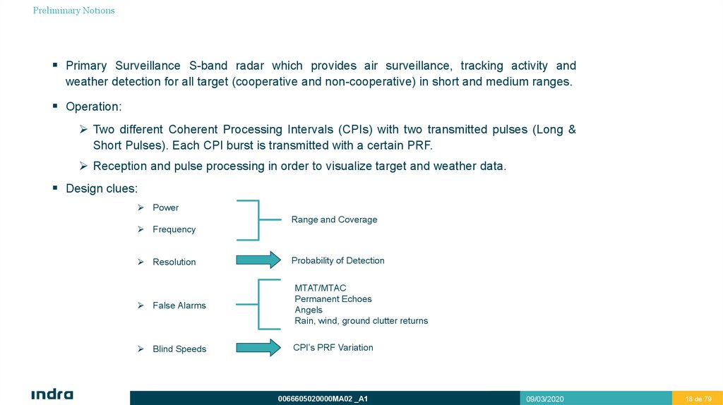
Preliminary NotionsPrimary Surveillance S-band radar which provides air surveillance, tracking activity and
weather detection for all target (cooperative and non-cooperative) in short and medium ranges.
Operation:
Two different Coherent Processing Intervals (CPIs) with two transmitted pulses (Long &
Short Pulses). Each CPI burst is transmitted with a certain PRF.
Reception and pulse processing in order to visualize target and weather data.
Design clues:
Power
Frequency
Resolution
Range and Coverage
Probability of Detection
False Alarms
MTAT/MTAC
Permanent Echoes
Angels
Rain, wind, ground clutter returns
Blind Speeds
CPI’s PRF Variation
0066605020000MA02 _A1
09/03/2020
18 de 79
18
19. Radar and Operation Concepts
Radio Detection and Ranging
Maximum and Minimum Range Determination
Doppler Concept
MTD-IV Processing
Blind Speeds
Frequency Diversity
Transmission Concepts
State Diagram
Stability
2
20. Radio Detection and Ranging
Radar and Operation ConceptsRadio Detection and Ranging
BASIC CONCEPT
A primary radar operates by radiating electromagnetic energy and detecting the echo reflected by objects.
The electromagnetic energy travels at constant speed, approximately the speed of light.
By using an antenna that focused the energy (directional beam), direction can be determined.
0066605020000MA02 _A1
09/03/2020
20 de 79
20
21. Maximum and Minimum Range Determination
Radar and Operation ConceptsMaximum and Minimum Range Determination
MAXIMUM RANGE
Radar system range is not related linearly to transmitted power.
In order to improve range, transmitted power must be increased in the order of R4.
R * 4 Pt
Pt Gt Ar
Pt Gt Ar
Pr
R 4
2
2
4
4 R
4 Pr
Pt R 4
There are two different possibilities to increase maximum range:
Transmitted power rising (Higher peak power).
Transmitted pulse length increasing (Higher average power).
MINIMUM RANGE
Minimum range achieved depends on the transmitted pulse length among other factors.
While transmitting, receiving is not possible. This fact will limit the minimum range.
0066605020000MA02 _A1
09/03/2020
21 de 79
21
22. Maximum and Minimum Range Determination
Radar and Operation ConceptsMaximum and Minimum Range Determination
Maximum range improvement
In order to improve maximum range, transmitted average power is risen by means of expanding transmission time pulse.
The disadvantages are a range resolution deterioration, besides minimum range will be affected.
Solutions:
1.Pulse Compression.
2.Short Pulse Transmission.
0066605020000MA02 _A1
09/03/2020
22 de 79
22
23. Maximum and Minimum Range Determination Pulse Compression
Radar and Operation ConceptsMaximum and Minimum Range Determination
Pulse Compression
Range resolution is related to pulse duration:
Goal: a long pulse transmission to achieve a good range, processed as a short pulse to get the SP resolution.
PULSE COMPRESSION:
This technique compresses the received long pulse signal into a short pulse.
0066605020000MA02 _A1
09/03/2020
23 de 79
23
24. Maximum and Minimum Range Determination Pulse Compression
Radar and Operation ConceptsMaximum and Minimum Range Determination
Pulse Compression
NLFM (Non Linear Frequency Modulation)
The pulse compression technique allows to convert a long and low resolution pulse into a short pulse (narrower bandwidth).
Such short pulse improves the range resolution with the same power.
The range resolution is related to the transmitted pulse width.
RRES
c
;
2 BW
PW = Pulse Width
Ex: 15000 m to 100µs
In a pulse compression system a chirp signal is transmitted. This means that the transmitted long pulse is considered as a set
of short pulses with different frequencies
In this case, the range resolution do not depends on its pulse width, it depends on the bandwidth of the transmitted signal.
The formula is:
RRES
c PW
2
;
BW = Band Width
0066605020000MA02 _A1
09/03/2020
24 de 79
24
25. Maximum and Minimum Range Determination Pulse Compression (Resolution)
Radar and Operation ConceptsMaximum and Minimum Range Determination
Pulse Compression (Resolution)
By means of this technique, resolution is a function of bandwidth, as seen before:
RRES
c
2 BW
PSR transmitted bandwidth is:1,942 MHz, achieving a minimum resolution of:
3x10⁸
RRES
77,24
6
3.884 x10
meters
On the other hand, taking into account the windowed factor=1,33:
77,24*1,33= 102,73 m
Resolution will be:
Resolution= range+range/2= 102,73+(102,73/2)= 154,1 m
0066605020000MA02 _A1
09/03/2020
25 de 79
25
26. Maximum and Minimum Range Determination Short Pulse Transmission
Radar and Operation ConceptsMaximum and Minimum Range Determination
Short Pulse Transmission
SHORT PULSE TRANSMISSION:
By means of pulse compression, resolution can be improved. However, system minimum range can not. Minimum range would
depend on pulse width (60 – 90 us).
Solution: transmitting a short pulse aprox. 1 us (nearby coverage).
This short pulse is a continuous waveform (non modulated).
Long pulse is used to further range (from the end of short pulse to the end of the coverage).
0066605020000MA02 _A1
09/03/2020
26 de 79
26
27. Doppler Concept Introduction
Radar and Operation ConceptsDoppler Concept
Introduction
Doppler Frequency:
Changes in electromagnetic frequency that occurs when the source of the radiation and its observer move toward or away
from each other.
Attending to the source radiation movement:
If the target is coming toward the observer, the frequency is higher.
If the target is moving away from the observer, the frequency is lower.
If the target is not moving, the frequency does not vary.
A clear example is the sound of a horn in a car, explained in the following slice.
0066605020000MA02 _A1
09/03/2020
27 de 79
27
28. Doppler Concept Introduction
Radar and Operation ConceptsDoppler Concept
Introduction
Sound is propagated at 1000 ft/s. ( 1 NM approx.. 6000 ft) 6 s/NM
Driver starts to press the horn at Observer-1 position and stops at Observer-2.
The car spends 60 sec. in covering the distance from observer-1 to observer-2 (1 nm.).
The sound spends 6 sec. in covering the distance between both observers (1 nm.).
Observer-1 hears the horn since driver starts to press the horn till 6 seconds after driver stops pressing it (66 sec).
0066605020000MA02 _A1
09/03/2020
28 de 79
28
29. Doppler Concept Introduction
Radar and Operation ConceptsDoppler Concept
Introduction
Observer-2 does not hear the horn sound till 6 seconds after the driver started to press it, however as far as driver stops pressing
the horn, the observer stops to hear it (54 sec.).
The driver hears the horn sound during exactly 60 sec.
Horn frequency = 10 KHz Transmission 10,000 cycles x 60 sec. = 6 x 10⁵ cycles.
Driver = 6 x 10⁵ cycles / 60 sec. = 10 KHz
Observer-1 = 6 x 10⁵ cycles / 66 sec. = 9 KHz
Observer-2 = 6 x 10⁵ cycles / 54 sec. = 11 KHz
The signal is the same for both cases. The difference performs in frequency, the later the lower the frequency, the earlier the
higher the frequency.
0066605020000MA02 _A1
09/03/2020
29 de 79
29
30. Doppler Concept Radar Application
Radar and Operation ConceptsDoppler Concept
Radar Application
Considering the relative movement of a target with respect a radar, the frequency from the echo varies as follows:
Higher frequency if target is coming toward the radar.
Same frequency if the range does not vary (circling the radar).
Lower frequency in case target is moving away from the radar.
The change in frequency is measurable as Doppler shift and can be used to determine the radial velocity of the target.
The PSR does not measure radial velocity of a target to calculate the targets speed. It uses Doppler shift to determine if there has been
a change from pulse to pulse in a given range cell (stationary or moving target).
0066605020000MA02 _A1
09/03/2020
30 de 79
30
31. Doppler Concept Radar Application
Radar and Operation ConceptsDoppler Concept
Radar Application
Calculation of Doppler shift:
Wavelength:
Frequency of Doppler:
0066605020000MA02 _A1
09/03/2020
31 de 79
31
32. Doppler Concept Radar Application
Radar and Operation ConceptsDoppler Concept
Radar Application
It is impossible to determine a Doppler change from one pulse echo returned from a target.
A series of identical pulse returns must be analyzed over time to determine the Doppler phase change. This grouping of pulses is
known as a Coherent Processing Interval (CPI). The Indra PSR uses 2 different CPI: 8 pulse CPI and 6 pulse CPI.
When coherent pulses are compared over a complete CPI, the magnitudes of the received signals will trace out the Doppler shift of the
target.
Moving targets will have different magnitudes because phase/amplitude of the received echo is changing.
A stationary target will produce an echo in the same phase (and amplitude) over a series of pulses. The peaks are all the same
amplitude, this “traces” a Doppler frequency of Zero for fixed targets.
0066605020000MA02 _A1
09/03/2020
32 de 79
32
33. MTD-IV Processing Doppler Speed
Radar and Operation ConceptsMTD-IV Processing
Doppler Speed
Doppler processing:
MTD Filter bank.
High resolution for targets flying from 20 to 800 knots.
MTD bank filter is made up of 8 and 6 FIR filters (notice that 8 implies high PRF and 6 low PRF allows identical filters: improving
resolution).
Filtering characteristics:
One filter per pulse
Improves Doppler resolution. High reliability for bimodal clutter resolution.
Zero velocity filter (ZVF)
Tangential target detection/clutter synchronous map updating.
The 8/6 bursts of every CPI are divided and processed by the 8/6 MTD Filters, obtaining 8/6 outputs based each on the 8/6 pulses.
0066605020000MA02 _A1
09/03/2020
33 de 79
33
34. MTD-IV Processing: Doppler Speed
Radar and Operation ConceptsMTD-IV Processing: Doppler Speed
8 coefficients MTD Filter Bank
6 coefficients MTD Filter Bank
10
10
0
0
-10
-10
-20
SNR Enhancement (dB)
SNR Enhancement (dB)
-20
-30
-40
-50
-30
-40
-50
-60
-60
-70
-70
-80
-80
-90
-90
0
0.1
0.2
0.3
0.4
0.5
0.6
Frequency (normalized @ PRF)
0.7
0.8
0.9
1
Radar velocity (knot)
0066605020000MA02 _A1
0
0.1
0.2
0.3
0.4
0.5
0.6
Frequency (normalized @ PRF)
0.7
0.8
0.9
1
Radar velocity (knot)
09/03/2020
34 de 79
34
35. MTD-IV Processing: Doppler Speed PRF Concept
Radar and Operation ConceptsMTD-IV Processing: Doppler Speed
PRF Concept
The Pulse Repetition Frequency (PRF) is the number of transmitted pulses per second.
Inverse parameter: PRI (Pulse Repetition Interval) or PRT (Pulse Repetition Time) is the time elapses between the beginning of one
pulse and the next.
The PRF establishes the maximum range and maximum non-ambiguous Doppler velocity.
Rmax( unambiguous )
c * PRT
c
2
2 PRF
0066605020000MA02 _A1
09/03/2020
35 de 79
35
36. MTD-IV Processing PRT Concept
Radar and Operation ConceptsMTD-IV Processing
PRT Concept
The PRT of the radar becomes important in maximum range
determination because target return times that exceed the PRT
of the radar system appear at incorrect locations (ranges) on the
radar screen.
Returns that appear at these incorrect ranges are referred to as
AMBIGUOUS
ECHOES.
RETURNS
or
SECOND
TIME
AROUND
0066605020000MA02 _A1
09/03/2020
36 de 79
36
37. Blind Speeds
Radar and Operation ConceptsBlind Speeds
PROBLEM:
• If a target has a Doppler frequency which is a PRF exact multiple, consecutive echoes will appear at the same Doppler signal point
eliminated because of being zero Doppler.
SOLUTION:
• Frequency diversity.
• PRF variation each CPI
Stagger 1.22 (60nmi) and 1.27 (80nmi). For both configuration the first blind speed is 800 knots.
PSR allows different PRFs pairs combination.
fr = PRF
=c/f
Ex. PRFb = 800 Hz PRFa = 1040Hz
Vb=(0,29(800Hz))/2,7Ghz = 85,9 knots
Vb=(0,29(1040Hz))/2,7Ghz = 111,7 knots
1NM =1,852 Km
Vb
0.29 PRF ( Hz )
f (GHz )
0066605020000MA02 _A1
09/03/2020
37 de 79
37
38. Blind Speeds
Radar and Operation ConceptsBlind Speeds
MTD filters determines first blind speed.
0066605020000MA02 _A1
09/03/2020
38 de 79
38
39. Frequency Diversity
Radar and Operation ConceptsFrequency Diversity
This method is used in order to improve the probability of detection, caused by fluctuations in the amplitude of the received signal.
Consist of assigning different frequencies for each pulse (long and short), f1 and f2.
f1 f 2 75.7 MHz
Short pulse (SP) and long pulse (LP) uses different frequencies.
Both are processed independently.
Possible interference between pulses will be eliminated.
0066605020000MA02 _A1
09/03/2020
39 de 79
39
40. Transmission Concepts CPIs + PRF + Frequency Diversity
Radar and Operation ConceptsTransmission Concepts
CPIs + PRF + Frequency Diversity
Azimuth sectored: synchronous clutter maps improves superclutter visibility.
CPI - 8
CPI - 6
4 us
Signal transmitted in 2 CPIs per beamwidth (1,4º) or 64 ACPs.
2 CPIs with different PRFs.
Subsequent frequencies F1 and F2 (separated 75.7 MHz) for LP and SP.
0066605020000MA02 _A1
09/03/2020
40 de 79
40
41. Transmission Concepts CPIs + PRF + Frequency Diversity
Radar and Operation ConceptsTransmission Concepts
CPIs + PRF + Frequency Diversity
PRT 1
PRT 1
CPI 1
PRT 2
PRT 2
1,4 º
CPI 2
0066605020000MA02 _A1
09/03/2020
41 de 79
41
42. Transmission Concepts CPIs + PRF + Frequency Diversity
Radar and Operation ConceptsTransmission Concepts
CPIs + PRF + Frequency Diversity
TRANSMITTED SIGNAL:
PTIP time elapses in synchronism generation.
TRIP time elapses in tx/rx.
Short pulse introduction Improves minimum range.
PRFa < PRFb Eliminate second around echoes.
Synchronous maps.
MTD Processing.
Polarization selection:
CIRCULAR (improves visibility in case of heavy rain clutter, for ex.).
LINEAR.
0066605020000MA02 _A1
09/03/2020
42 de 79
42
43. State Diagram
Radar and Operation ConceptsHeight
State Diagram
1
Long/Short Pulse transmission
Short Pulse , High Beam reception
3 Long Pulse, High Beam reception
4 Long Pulse, Low Beam reception
2
High
Beam
Low
Beam
4
3
2
1
D1 nm
D2 nm
Range
STANDARD DIAGRAM:
According to range: Short or long pulse echo maximum range or minimum instrumented range.
D1-D2: depends on long pulse length (configurable between 60 – 90us).
This is an example of a typical configuration, however it will be configured by sectors. According to each site (two states per
pulse can be configured).
Advantage, switching processing is performed by software, therefore any mechanical switch is used in order to select channels
(seamless switching).
0066605020000MA02 _A1
09/03/2020
43 de 79
43
44. Stability
Radar and Operation ConceptsStability
STABILITY COHERENT RADAR
Outstanding measurement in radars which uses Doppler (instabilities can produce Doppler errors).
The transmitted signal is digitally generated by means of DDS (Direct Digital Synthesis) techniques.
Stable transmitter.
Is able to amplify the transmitted signal without affecting to stability. Three different points to check stability in CMS.
Very stable crystals (coherent oscillators) are used to generate the final frequencies for transmitted signals and also, the clocks (STALO y COHO).
0066605020000MA02 _A1
09/03/2020
44 de 79
44
45. Design Features
Evolution
Main Features
Characteristic Summary
3
0066605020000MA02 _A1
09/03/2020
45 de 79
45
46. Evolution
Design FeaturesEvolution
Collects features about Indra 3D radar (Lanza).
Designed following the EUROCONTROL and ICAO Specifications.
Includes additional redundancy levels (multiple combinations allowed). Reliability, availability and maintainability.
High capacity to adapt the system on environment.
Friendly user interface and adaptation tools (graphical optimization).
Powerful integrated BITE.
Full solid state transmitter.
Graceful degradation and hot repair.
Dual beam antenna.
Seamless switching.
0066605020000MA02 _A1
09/03/2020
46 de 79
46
47. Main Features
Design FeaturesMain Features
TAR and TMA applications.
ASR system provides improvement levels of safety, integrity,
maintainability and reliability to enhance the quality of service and
overall safety of operation.
Full solid-state technology.
Operation as Stand-alone or co-mounted with a SSR radar.
Westinghouse and Northrop Grumman heritage plus Indra military 3D
PSR “Lanza” knowledge.
0066605020000MA02 _A1
09/03/2020
47 de 79
47
48. Characteristic Summary System Performance
Design FeaturesCharacteristic Summary
System Performance
Frequency
2,7 to 2,9 GHz
Frequency diversity/agility
2 frequencies (LP/SP)
75,8 MHz freq diversity. Possible exchange of frequencies for
subsequent CPIs or scans.
Peak Power
20 kW min for 10 PA configuration
25 kW min for 12 PA configuration
RF Blanking
Sectored in azimuth
Pulse width
Short Pulse: 1,2 us
Long Pulse: 60 to 90 us
PRF
735 to 1300 Hz (configured in exploration modes map)
Sub-clutter Visibility
> 42 dB (distributed clutter)
Detection Range
60 NM , 80 NM or 100 NM
Stability
> 60 dB
0066605020000MA02 _A1
09/03/2020
48 de 79
48
49. Characteristic Summary System Performance
Design FeaturesCharacteristic Summary
System Performance
Resolution
Range: 155 m (80%) LP
230 m (80%) SP
Azimuth: 2,8º rms
Accuracy
Range: 50 m rms, typ 38 m
Azimuth: 0,15º rms, typ 0,12º
MTBCF
> 45.000 hours
Availability
> 99,999%
MTTR
< 20 min.
Useful life cycle
15 years
Remote Control and Monitoring
Graphical Friendly-User Integrated PSR-MSSR Interface
0066605020000MA02 _A1
09/03/2020
49 de 79
49
50. Characteristic Summary Antenna Performance
Design FeaturesCharacteristic Summary
Antenna Performance
Beams
Low beam for transmission
High and Low beams for reception
Gain
> 34 dB (Low beam)
> 32,5 dB (High beam)
Azimuth Beamwidth
1,45º ± 0,05º
Elevation Beamwidth
> 4,6º (Low Beam)
> 4,8º (High Beam)
Cosecant squared to + 40º
Rotation speed
12/15 rpm
Polarization
Linear (vertical)
Circular (right-handed)
0066605020000MA02 _A1
09/03/2020
50 de 79
50
51. Characteristic Summary Receiver and Processor Performance
Design FeaturesCharacteristic Summary
Receiver and Processor Performance
Noise Figure
< 2,35 dB
Sensitivity
- 108 dBm (Short Pulse)
- 126 dBm (Long Pulse)
Dynamic Range
84 dB, before pulse compression
STC
2 RF and 1 digital
Processing Type
MTD-IV Doppler filter bank 6/8 (low/high PRF)
False Alarm Control
CFAR in each filter, Clutter Synchronous Map, Clear Day Map, Geocensor Map, Threshold Adaptive Map, Interference/Suppression
detect, MTAT, MTAC,AP detection
Weather Processing
US-NWS 6 levels detection
Doppler filters for Ground clutter suppression
Processing Capacity
1500 plots/scan
1000 Tracks/scan
False Alarms
10 each scan (at the tracker output in normal clutter conditions)
ADC
14 bits @ 93.2144 MHz
0066605020000MA02 _A1
09/03/2020
51 de 79
51
52. General Description
System Architecture
System Elements
Functional Description
Operation and Monitoring
4
0066605020000MA02 _A1
09/03/2020
52 de 79
52
53. System Architecture PSR + MSSR
General DescriptionSystem Architecture
PSR + MSSR
0066605020000MA02 _A1
09/03/2020
53 de 79
53
54. System Architecture Block Diagram
General DescriptionSystem Architecture
Block Diagram
OUTDOOR EQUIPMENT
INDOOR EQUIPMENT
GRPG 1
0066605020000MA02 _A1
GRPG 2
09/03/2020
54 de 79
54
55. System Architecture: Interfaces
General DescriptionSystem Architecture: Interfaces
0066605020000MA02 _A1
09/03/2020
55 de 79
55
56. System Architecture External Interfaces
General DescriptionSystem Architecture
External Interfaces
DATA
PROCESSOR
ASTERIX Cat. 34 & 48 (1 & 2)
ATCC
PLOTS & TRACKS
WEATHER
PROCESSOR
ATCC
ASTERIX Cat. 8
WEATHER MESSAGES
0066605020000MA02 _A1
09/03/2020
56 de 79
56
57. System Architecture Interfaces
General DescriptionSystem Architecture
Interfaces
0066605020000MA02 _A1
09/03/2020
57 de 79
57
58. System Architecture Antenna and Pedestal Group (APG)
General DescriptionSystem Architecture
Antenna and Pedestal Group (APG)
APG
0066605020000MA02 _A1
09/03/2020
58 de 79
58
59. System Architecture Antenna and Pedestal Group (APG)
General DescriptionSystem Architecture
Antenna and Pedestal Group (APG)
ROTARY JOINT
ANTENNA
PEDESTAL
0066605020000MA02 _A1
09/03/2020
59 de 79
59
60. System Architecture Dual Rotary Control Group (DRCG)
General DescriptionSystem Architecture
Dual Rotary Control Group (DRCG)
DRCG
0066605020000MA02 _A1
09/03/2020
60 de 79
60
61. System Architecture Transmitter, GRPG and MWG
General DescriptionSystem Architecture
Transmitter, GRPG and MWG
MICROWAVE GROUP
TRANSMITTER
GRPG
0066605020000MA02 _A1
09/03/2020
61 de 79
61
62. System Architecture Transmitter
General DescriptionSystem Architecture
Transmitter
CIRCUIT BREAKER
CONTROL/MONITOR
BOARD
10 RF AMPLIFIER PANELS
(FAIL-SOFT)
REDUNDANT PREAMPLIFIERS
CABINET
REDUNDAT BLOWERS
REDUNDANT BULK POWER
SUPPLIES
REDUNDANT MULTI VOLTAGE
POWER SUPPLIES
0066605020000MA02 _A1
09/03/2020
62 de 79
62
63. System Architecture Dual Receiver Cabinet (GRPG)
General DescriptionSystem Architecture
Dual Receiver Cabinet (GRPG)
SDG:
Signal Distribution Group.
MWCG:
Microwave Control Group.
CPC:
Central Processor Computer.
RXG:
Receiver Group.
EPG:
Exciter and Processor Group.
SWR:
Switch Router.
TTSU:
Temperature Sensor Unit.
MWPG:
MWG Polarizer and Input RF
Switches Power Supply Group.
CHANNEL 1
CHANNEL A
CHANNEL 2
CHANNEL B
SDG
MWCG
MWPG
SWR1
SWR2
CPC1
CPC2
RXG2
RXG1
EPG1
0066605020000MA02 _A1
EPG2
09/03/2020
63 de 79
63
64. System Architecture Microwave Group (MWG) and Compressor Dehydrator
General DescriptionSystem Architecture
Microwave Group (MWG) and Compressor Dehydrator
MWG
Compressor
Dehydrator
0066605020000MA02 _A1
09/03/2020
64 de 79
64
65. System Architecture Channel Distribution for Microwave Group (MWG)
General DescriptionSystem Architecture
Channel Distribution for Microwave Group (MWG)
WAVEGUIDE POWER
LOAD (WPD)
SHELF SWITCH ASSEMBLY
HARMONIC FILTER
BIDIRECTIONAL
COUPLER
WAVEGUIDE
DUPLEXER (WDD)
CRCH
CRCH
COAXIAL SWITCH
WAVEGUIDE SWITCH (WGS)
COAXIAL RECEIVER CHANNEL (CRCH)
WAVEGUIDE RECEIVER PROTECTOR (WRP)
FILTER AND LNA UNIT (FLU)
0066605020000MA02 _A1
09/03/2020
65 de 79
65
66. Functional Description Antenna and Pedestal Group (APG)
General DescriptionFunctional Description
Antenna and Pedestal Group (APG)
APG assembly performs RF signal radiation and reception with a specific power, directivity and coverage.
Antenna
S-band reflector (until 40º in elevation).
Two feedhorns.
Polarizer.
Pedestal
Mechanical support and physical interface with antenna platform.
Two motors which carry on the antenna turning.
Rotary Joint
Two encoders.
RF signal path between the antenna and the radar.
Power supply and control signals pass though slip-rings (control
and polarizer feed).
DRCG
Control and monitoring of motors and all the elements of the APG.
0066605020000MA02 _A1
09/03/2020
66 de 79
66
67. Functional Description Transmission Path Diagram
General DescriptionFunctional Description
TRANSMIITTER
Transmission Path Diagram
0066605020000MA02 _A1
09/03/2020
67 de 79
67
68. Functional Description Transmission Path
General DescriptionFunctional Description
Transmission Path
EPG (Frequency Generation).
Oscillator signal generation (STALO y COHO).
Transmitted signal generation and up-conversion (TXGU).
Solid state transmitter.
Peak Power: 22kW
Radiation of two pulses each transmission period.
Redundancy in order to provide high reliability and graceful degradation.
N+1 redundancy.
Signal samples in three different points stability checking.
BITE reports excess duty cycle, VSWR…
Control from SCP (EPG in the receiver) TXCU communication.
MWG
Signal path from transmitter (LOW-TGT) to antenna.
0066605020000MA02 _A1
09/03/2020
68 de 79
68
69. Functional Description Reception Path Diagram
General DescriptionFunctional Description
Reception Path Diagram
RXG 1
DDPG (EPG 1)
DRU 1
CPC A
CPC 1
2
CPC B
DRU 2
RXG 2
0066605020000MA02 _A1
DDPG (EPG 2)
09/03/2020
69 de 79
69
70. Functional Description Reception Path
General DescriptionFunctional Description
Reception Path
MWG (Microwave Group).
Receives echoes through antenna and route them toward the receiver (four independent paths).
HIGH-TGT.
LOW-TGT.
HIGH-WX.
LOW-WX.
MWCG (Microwave Control Group).
Through two boards, RFCSU (High and Low) channel 1 or 2 for MWG or RXG are selected. Cross selection is possible.
The selection is controlled by MWCU.
RXG (Receiver Group).
STCU, performs a certain attenuation level depending on the STC configuration map.
SRXU, carries out frequency filtering, down-conversion, amplification and output signal adjustment.
LOSDU, distributes LO1 and LO2 signals to SRXUs.
0066605020000MA02 _A1
09/03/2020
70 de 79
70
71. Functional Description Reception Path
General DescriptionFunctional Description
Reception Path
EPG (DDPG: Digital Demodulator and Processor Group).
DRU, performs down-conversion to baseband and A/D conversion.
GPB, carries out signal and data processing.
EPG (SCBG: Synchronization, Control and BITE Group).
SYNU, system synchronism generation.
CBU, system control and BITE reception.
SDG (Signal Distribution Group).
IFCSU, routes IF signals from SRXU to SCBG (base band demodulation and processing).
SDCU, collect SDG BITE signals. Redundancy control through CBU (Control and BITE Unit).
AGSU, selects operative groups if locally controlled.
TSU, conversion and distribution of ACP/ARP signals.
0066605020000MA02 _A1
09/03/2020
71 de 79
71
72. Functional Description Test Signals
General DescriptionFunctional Description
Test Signals
RXG
IF test signal from TXGU TISMU SRXUs.
MWG
RF test signal from TXGU MWG
EPG
Digital test signals.
1
2
72
0066605020000MA02 _A1
09/03/2020
72 de 79
72
73. Functional Description Stability Signals
General DescriptionFunctional Description
Stability Signals
RXG
Stability control (three points of the transmitted signal are monitored) in TXG.
These samples are sent from TXG to TISMU and checked through STCU.
0066605020000MA02 _A1
09/03/2020
73 de 79
73
74. Functional Description Control & Bite (SCBG in EPG). Redundant System
General DescriptionFunctional Description
Control & Bite (SCBG in EPG). Redundant System
Redundant dual channels for reception and signal processing.
ANTENNA
Automatic fault detection possible automatic channel switching.
SCBG (System Control and Bite Group) receives status signals and sends control commands.
MWG 2
MWG 1
SDG: (SDCU) redundancy control (operational/stand-by channels).
RFCSU
RXG 1
SDG: Manual switching, local control (AGSU).
RXG 2
IFCSU
High operation flexibility.
EPG 1
SDCU
EPG 2
TRANSMITTER
MWG 1
APG
RXG 1
EPG 1
CPC 1
TXCU 1
TXG PRPA 1
TXG PA
SDG
MWG 2
RXG 2
EPG 2
CPC 2
0066605020000MA02 _A1
TXCU 2
TXG PRPA 2
09/03/2020
74 de 79
74
75. Functional Description Main System Functions
General DescriptionFunctional Description
Main System Functions
System Controlling.
Antenna (turning, polarization).
Transmitter (radiation on/off).
Possibility of switching in various points.
Operation mode (Main/Standby).
Reception map configuration (state map).
System stability measurement.
Noise figure system measurement.
Alarms / BITE.
0066605020000MA02 _A1
09/03/2020
75 de 79
75
76. Functional Description Main System Functions
General DescriptionFunctional Description
Main System Functions
Performance evaluation.
Test target injection.
Permanent Echoes.
Signal processing.
Pulse compression.
MTD filtering. CFAR techniques.
Clutter and clear day map generation.
STC map generation.
Range, azimuth and doppler estimation.
Weather signal processing.
Data processing.
Azimuth detection correlation.
Track generation.
Weather data detection (weather map).
0066605020000MA02 _A1
09/03/2020
76 de 79
76
77. Operation and Monitoring Control and Monitoring System Main Screen
General DescriptionOperation and Monitoring
Control and Monitoring System Main Screen
0066605020000MA02 _A1
09/03/2020
77 de 79
77
78. Operation and Monitoring Control & BITE
General DescriptionOperation and Monitoring
Control & BITE
Powerful BITE.
Graphical report of failures in all levels of Control and Monitoring applications using text and colour coded status elements.
RMMS indication:
PSR Failure
UCS indication:
GRPG Failure
LRU indication:
Module failure
All failures are reported and are monitored in both Local or Remote Control and Monitoring System (SLG or SRG).
BITE is collected by the control board of each group and sent to the CBU(in control and BITE group in EPG).
0066605020000MA02 _A1
09/03/2020
78 de 79
78