
")


")

")

")

")


")


")
")


 electronics
Similar presentations:

")
")


Switching systems
1. switching systems
2. The concept of pulse code modulation (PCM)
Conversion of the primary continuous analog signal into a digital code called PCM(PCM) [1, 2, 4,5]. In telecommunications in the binary sequence is selected as the
code base, implemented with minimal hardware costs. The main operations in the
PCM sampling operations are time quantization (sampling the level at a discrete
time signal) and encoding.
Sampling the analog signal time is a transformation in which the analog signal
representing the parameter is the sum of its values at discrete points in time.
In digital communication systems, used uniformly sampling an analog signal (the
signal samples are produced at regular intervals). When used uniform sampling: Δt
sampling interval (time interval between two consecutive samples of a discrete
signal) and FD sampling frequency (the reciprocal of the sampling interval). The
value of the sampling interval is chosen according to the Kotelnikov theorem
(Shannon).
3. Kotelnikov Theorem
According to the Nyquist theorem, any analog (continuous), the signal canbe sampled, and rebuilt on the opposite end, if the sampling frequency is
twice the upper frequency of the signal.
Channel tone (main channel analog telephone channel) should occupy a
strip of 300 ... 3400 Hz. Consequently, the sampling rate must be at least: Fs
= 2h3400 = 6800 Hz. According to the recommendations of the ITU
(International Telecommunication Union) for a signal transmitted on the
voice channel, accepted sampling rate Fs = 8000 Hz. This facilitates the
implementation of the frequency of the DSP hardware filters.
4. The quantization of signal
The sampled amplitude pulses correspond to the instantaneousvalues of the signal. These transformations are called pulse amplitude
modulation. Discrete transmitted one after another cyclically in the
form of compacted temporarily PAM signals
At any quantization of message processing appliances and
transmission systems has a finite resolution, so there is no need to
transmit all the infinite number of amplitude values of continuous
signals, it is possible to limit a finite set. Those permitted to transmit
the signal amplitude values are called quantization levels, the choice of
their number determines the quality of the transmission of electrical
signals
PAM signal obtained by sampling is quantized by level. The difference
between two adjacent levels permitted for transmission are called
quantization step-Δ.
The difference between the true value of the reference signal and the
quantized value is called quantization error or noise.
5. Converting an analog signal to PCM signal
6. Coding the quantized reference
Encoding the quantized frame called the identification ofthe frame with the code words. In practice the apparatus is
used in the binary PCM codewords, wherein each binary
word corresponds to a signal level of quantization.
According to the recommendations of the ITU, was
adopted 256 quantization levels (128 positive and 128
negative levels), and the codeword length - 8 binary digits
(bits), Figure 3.1, the
The first eight-digit code combination determines the
polarity of the encoded signal amplitude (1- positive signal
"+" 0 - negative "-"); 2,3,4 bits define the top of the segment
in which the signal is located; 5,6,7,8 bits define the
number of levels in the segment.
7. Structure of the cycle with 2 Mbit / s speed
Voice over separate channels for voice frequency telephone network iscarried out in the range from 300 Hz to 3400 Hz. For organizations
using digital switching primary flow path PCM 30/32.
And multiframe cycle structure of a PCM-30 system are shown in
Figure cycle consists of 32 time slots. Multiframe consists of 16 cycles.
Cycle TC = 125 ms, which determines the frequency of repetition cycles
Fts = 8 kHz. The duration is multiframe 16h125mks = 2ms. For each
channel in a cycle stands K.I interval = 3.9 ms. Each channel is
designed for the transmission of information of 8-bit binary code, then
the duration of one bit (bit) will be b = 0.49 microseconds. The
throughput of one time slot of 64 kbit / s, then the capacity of the
primary standard PCM highway is 64 * 32 = 2048 kbit / s. The loop
PCM timeslots 0 and 16 are overhead channels and slots 1 to 15 and 17 to
31 are information channels.
8. Structure of the cycle with 2 Mbit / s speed
As shown in Figure 1.2, a digital clock positions 2-8 takes zero time slot in everysecond cycle. Cyclic clock signal is a combination 0011011. To eliminate the
possibility of cyclic odd clock cycles simulate zero symbols 2-8 2 symbol
intervals in these ranges is given the value 1. multiframe clock allowing to carry
out cycles per superframe count is a combination of 0000 and occupies bit
intervals 1- 4 slot 16 in the loop 0.
Timeslot 16 is used for transmitting signaling. In each cycle two alarm signals
transmitted voice channels.
The designations in Figure 1.2: TC - telephone channel; RO, .... RI5 - cycles in
the superframe; SK - timeslot; B1, .. B8 - code word length of 8 bits; N - bit is
reserved for international use (the symbol is not defined, now has to take the
value of 1); A - Transfer of alarm signal to the equipment end of the PCM link;
VI, .... V5 - symbols intended for national use (on digital paths crossing the
state borders), these symbols should have a value of 1); x - the symbol of the
reserve (in the case when not in use "must be set to I); y - the symbol used to
indicate a way out of multiframe clock; a, b, c, d- code for common channel
signaling Organization (ACS), if b, c and n d are used for ACS, they must have
the following values: b = 1, c = 0, d = I.
9. The structure of the cycle and multiframe of PCM-30 equipment
The structure of the cycle and multiframe of PCM30 equipment10. Definitions and concepts of the switching
Switching - is a process of establishing a connection between certain input and output of the systemand maintain it for the duration of the transmission of user information, and then disconnect. There
is the following switching techniques [1, 2, 4]:
- Switching channels;
-Switching messages;
- Packet switching.
When switching channels, first through the link is created, then the communication channel in real
time, and information can be exchanged after the exchange of communication channel collapses.
When switching communications: communication is performed not in real time, through the
connection between the input and output of the system is not required and redundant messages are
not lost, but saved and passed on with a delay.
With packet switching message is divided into blocks of a certain size - packages. Each packet is sent
independently, once freed available communication channel. On the receiving side are restoring
messages from packets received at different times and can be in different ways.
It is called switching one-coordinate at which the connecting paths in the system are separated from
one another by separation basis, where the sign of separation is meant the parameter on which
separation occurs in the system connecting paths between input and output.
Digital switching is a process in which the connections between the input and output of the system is
set by the operation of the digital signal without converting it to analog.
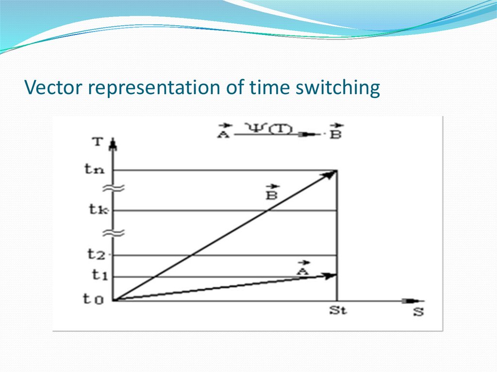
11. The principle of transformation of the time coordinate of the digital signal (the principle of time switching)
Unit or module performing the function of theswitching time of the digital signal is called a time
switching stage or T-stage (from time- time).
Reorder one timeslot outgoing PCM lines compared
with the incoming voice data transmission means from
one subscriber to another. This is the time switching
principle (sometimes referred to interchange time
slots or moving information from channel to channel).
12. Illustration of time switching principle
13.
Vector representation of time switching14. The principle of transformation of the time coordinate of the digital signal (the principle of time switching)
Using a vector representation of a digital switch,Figure 2.2, into the space-time coordinates allows a
somewhat different principle to describe the time of
switching. If we assume an orthogonal transformation
of temporal and spatial coordinates of the digital
signal, we obtain the expression:
15. Deciphering formula
For time switching ψ (s) = 0. Operation ψ (t) is a delayoperation on a specific codeword set time.
Time switching module disadvantage is that it is able
to switch channels only one digital line. Therefore,
switching N PCM lines must be N modules. A
organization for interconnecting different PCM lines
in series with it is necessary to include the additional
equipment - unit of spatial or space-time switching.
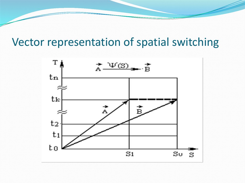
16. The principle of conversion of the spatial coordinates of the digital signal (the principle of spatial switching)
Unit or module of the digital switching field,performing spatial switching digital signal is called a
spatial switching stage or S-stage (from space- space).
The essence of the spatial coordinate conversion of
digital signals is to move the time slot of the PCM line
into one another while maintaining the order of the
slot in the loop structures of the two lines, Figure 4.3.
Vector representation of this transformation is shown
in Figure 4.4. In this case, once again assumed an
orthogonal transformation
17. Illustration of the principle of spatial switching
18.
Vector representation of spatial switching19. The principle of conversion of the spatial coordinates of the digital signal (the principle of spatial switching)
Vector representation of this transformation is shownin Figure 4.4. In this case, once again assumed an
orthogonal transformation
20. Deciphering formula
CP Digital, built on the space switching modules arewidely used in the early stages of the digital exchanges,
due to ease of implementation and low cost of
implementation. However, the lack of space switch,
which is switched in only one channel of the same
name for all incoming and outgoing PCM lines (which
means the lock when connecting dissimilar channels),
led to the fact that at present, these modules are used
only in combination with other types of switch
modules
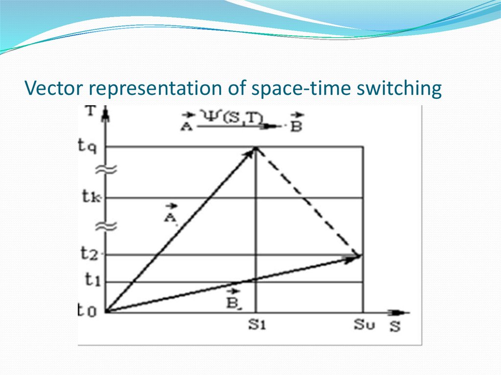
21. The principle of the space-time switching
Unit or module implements a space-time coordinatetransformation of a digital signal, called S / T- stage.
The essence of the conversion coordinates space-time
digital signals is to move a predetermined time slot of
a PCM line to another to change the order of the slot in
the loop structures of the two lines, Figure 4.5.
22. Illustration of the principle of space-time switching
23.
Vector representation of space-time switching24. Digital switching fields 1, 2, 3, 4, 5 th grade
25. Principles of the construction of DSF
Switching the system reflects the principles of the internalconstruction of switching stations and is a collection of hardware
designed for operational switching.
Switching system implementing digital switching function, called a
digital switching system (DSS).
In a digital switching system switching function provides a digital
switching network (DSN). Management of all processes in the
switching system carries out control complex.
Digital manual is based usually on the basis of the link. Digital link
manual steps referred group (S-, T or S / T-), realizing the same
function of coordinate transformation of the digital signal. Depending
on the number of units are distinguished double, triple and multi-tier
manual.
Digital manual called uniform if any connection to it is established
through the same number of units. Most modern DSS have
homogeneous digital manual.
26. Features of construction of multi-digital manual
1. Digital manuals are built using a certain number ofmodules.
2. The Digital manuals have a symmetric structure.
Under understand symmetrical structure in which the
units 1 and N, N-2 and 1, 3, ... N-2 are identical in type
and number of switching units.
3. Digital manuals almost always are duplicated
because of the criticality problems in the connection
box to the functioning of the whole system.
4. Digital manuals are four- because digital lines that
carry time multiplexed PCM signals as four-wire.
27. Five classes
Taking into account the symmetry and the modular construction of the entire set of synchronousdigital manual switching with the functional completeness can be divided into five classes [1, 2]. In
each class, you can select the basic structure and substructure formed by adding additional switching
elements with advanced multiplexing (MUX) and the subsequent demultiplexing (DMUX) group of
digital paths.
1. The basic structure: S 'k - T' r - S 'k.
Substructure: MUX - S 'k - T' r-S 'k - DMUX.
A special feature of the field is the presence of S-stage in the first and the last link, the order of the Tand S-levels within a field - a random compliance with the rules of symmetry.
2. The basic structure: T 'k - S' r - T 'k.
Substructure: MUX - T 'k - S' r - T 'k - DMUX.
A special feature of the field is the presence of T-stage in the first and the last link, the order of the Tand S- steps within the field - voluntary compliance with the rules of symmetry.
3. The basic structure: S / T 'k - S' r - S / T 'k.
Substructure: MUX - S / T 'k - S' r - S / T 'k - DMUX.
4. The basic structure: S / T 'k.
Substructure: MUX - S / T 'k - DMUX.
5. Ring digital switching fields.
Although ring manuals are based on the S / T-stages (ring connector), and are in fact a kind of field
grade 4, but in view of their importance and features of construction decided to allocate them in a
separate class.
28. CSF of the First Class
Initially, the basis for these types of units CSF spatialswitching stage were taken, such as: PBX Sintel, DEX-T
had a structure field type S-S with parallel switching
method. But spatial switches have a greater probability
of internal blocking, so in practice become widespread
structure where space switching stage S-divided time T
stages such CSF combined symmetric field.
29. The basic structure of a first-class CSF
30. CSF of the second class
These types of systems are CSF: NEAX 61 (Japan), №4 ESS (US),AXE 10, D70, FETEX150.
Features CCU second class:
- The use of additional S-steps increases the capacity and
throughput capacity of the field, but do not affect the principles
of its functioning;
- Inputs prior multiplexing actually provides a secondary seal
incoming digital lines, the subsequent demultiplexing and
restores them at the outputs, resulting in increased throughput
without additional S-stages;
- To increase the data processing speed of the gearbox on the
input, tends to produce sequentially convert to parallel. For this
purpose, each incoming line is installed converter serial-parallel
type, and on the output - parallel to serial.
31. The basic structure of the second class CSF
32. CSF of the third class
These types of systems are CKP: MT 20/25 (France), System X(DSS) (United Kingdom), EWSD (Germany). GDTS (USA), the
DTS-11 (Japan) and many others, on which you can build local,
long distance and transit stations.
NBI in this class are universal, because they allow to build the
same type of switching system for virtually the entire range of
capacities: small, medium and large. When this occurs the
container capacity by increasing the number of spatial switching
units, passing from simpler structures S / T-S-S / T to more
complex S / T-S-S-S / T. Often the design of the switching field
temporal and spatial switching stage are combined into
respective blocks: a block time switching and space switching
unit. Then build CP capacity is done by simply adding a certain
amount of BTS and BSS (block of time switching and block of
space switching)
33. The basic structure of the third class CSF
34. CSF of the fourth class
These types of systems are CSF: PROTEL UT andothers. fourth grade MSC are widely used due to the
facilities to increase capacity of the field simply by
adding S / T-stages performed in a universal
integrated circuit (IC).
The basis of the S / T-stage switching elements
comprise or modules. When designing the capacity of
a small PBX manual can be built using a single link S /
T-stage having only one module (capacity typically 8/8
to 32/32 incoming / outgoing PCM lines)
35. The basic structure of the fourth class CSF
36. CSF of the fifth class
These types of systems are CSF: ITT1240 (USA), S12Alcatel, but the ring CSF not widespread. Links
annular fields are built mostly on the ring of digital
switching elements (DSE) .Such DSE consists of
connecting units (CU) and Group Switching Unit
(GSU). One power supply consists of two DSE.
Number of BP and BGK in stages depending on the
number of connected terminal units (TU). The
number of planes depends on the average load
induced TU and predetermined Quality of Service
from
37. The basic structure of the fifth class CSF
38. Construction of a subscriber interface in digital switching systems
Digital Switching Systems Operation is surrounded by varioustelecommunication equipment other ATS (digital and analog), different user
devices, transmission systems. CSC must provide an interface (interface) with
analog and digital subscriber line (AL) and transmission systems [1, 2, 4].
Called interface or boundary between two functional units, which is defined by
functional characteristics, common characteristics of the physical connection,
signal characteristics and other characteristics depending on the specifics.
The interface provides a one-time definition of connection settings between
the two devices. These parameters include the type, number and function of
connecting circuits, and the type and form of a sequence of signals that are
transmitted by these circuits.
Interfaces digital ATS Figure 6.1:
- An analog subscriber interface;
- Digital subscriber interface;
- ISDN subscriber interface;
- Network (digital and analog) interface.
39. Interfaces of digital switching systems
40. Analog and digital terminals
To enable analog lines (Subscriber or institutionalproduction exchanges (PBXs) in the device, providing
access to
Digital station) uses Z-type interfaces (Z1, Z2, Z3).
To enable digital lines U interfaces have been identified
and V. They are used to activate the AL at the main access
to the ISDN network. V2 interface is designed to enable
digital substations rate of 2048 kbit / s. Through V3
interface include digital equipment at the primary access to
integrated networks, such as digital PBX. Multiplexer
equipment to digital PBX interface is activated through V4.
For PCM multiplexers used to connect analog remote
substations and analog PBX, the interface used for
connecting digital access networks
41. Analog subscriber interface and the problem BORSCHT
With the creation and implementation of digitalexchanges have a problem switching to a digital PBX
analog subscriber line (AL) to an analog telephone
(SLT). These problems are described by the acronym
BORSCHT
42. Description of BORSCHT function
43. Description of BORSCHT function
44. Addressing of organizations analog subscriber interface implementation
- Approval by the form of the transmitted voice signal (functionCoding - coding) and in connection with the transition from a
two-wire circuit speech path to the four-and vice versa (feature
Hybrid - feature difsystem);
- Agreement on the levels of transmitted signals: in the direction
of the TA sent to the high-level signals (function Battery feed
and Ringing), in the direction of the PBX signals must not be
sent (ATSC built on LSI and VLSI powered 5 ... 12 V).
- Providing subscriber signaling (Signalling function - alarm).
Testing functions (control) and Overvoltage protection
(protection from hazardous voltages) do not apply directly to the
company analog interface of the SL, but their implementation
allows you to automate the process of operation of the SL and
TA, as well as ATSC protect against hazardous voltages.
45. Network interfaces of digital ATS (STS)
46. The concept of network interfaces of STS
According to the recommendations Q.501-Q.517 analog ordigital trunks through the STS includes a network interface
types A, B and C [1, 4].
Connected via an interface A digital paths, multiplexed
PCM-30 apparatus (2048 kbit / s) or PCM-24 (1544 kbit / s).
The interface for connecting digital paths multiplexed
PCM-120 apparatus (8, 844 kbit / s).
Analog two or four wire line included in the station end
digital exchange via interface C. The analog-to-digital
converters for these lines are part of a digital STS
equipment.
47. Features connecting network interfaces with a DSP
In conjunction with other digital STS digital STS, or when establishing between analog and digitalSTS digital transmission system arranged on the first digital interface. In this case, it realized one of
the most important advantages of CSF, which is to create a single digital representation of
information in a path of "transmission - switching".
Thus, the representation of the speech signal as a PCM signal (64 kbit / s, 8 bits in the code word) is
similar both for digital switching systems, and apparatus for the DSP. But there are several problems
with regard to interfaces and DSP digital switching systems. In - First, the telephone network can be
used (and are actually used) DSP are not included in the hierarchy of the ITU transmission systems
(eg, PCM - 15, special DSP AL). In - the second, due to the peculiarities of construction of digital
manual cycles structure inside them is different from the structure of DSP cycles. ITU has determined
that they will not put forward any demands regarding the structure of the PCM cycle paths within the
CSK. Digital PBX Developers have the ability to carry out at its own discretion temporary seal PCM
streams (secondary Multiplexing) STS, change the length of the codeword. B - Third, encoding words
in the PCM line and inside the STS varies.
To the digital interface, DSP and digital STS imposed two sets of requirements: power and logic.
The need to harmonize structures cycles indicates that the input should be formed DSP cycles
corresponding to the requirements of this DSP. This agreement is usually carried out in the secondary
demultiplexing within the STS.
The logical transformation comprises matching NDV3 linear code signal into a binary code and vice
versa to synchronize the input signals in accordance with clock signals stations.
48. Interface with analog trunks and connecting lines (CL)
For connection of analog and digital PBX usingexisting or newly created analog physical connecting
line (SL). In this case, for each analog trunk signaling
system organized a separate interface. Figure 7.1 shows
the principles of coordination of digital EATS 200
urban stations such as ATSC and ATSKU for two-wire
physical trunks with signaling DC
49. EATS 200 communication scheme with electromechanical STSC (RSL - CO relays)
50. Driving matching device
51. Interface with analog trunks and transmission systems
Matching device, Figure 7.2, can be divided into two parts:the channel and signal synchronization. Scheme placed in
channels matching device is converted DC signal sending
physical connecting line signals supplied to the control
unit. The channel portion does not produce any logical
processing signals coming from the line.
The control unit gates signaling information of each trunk
in 2 ms. By carrying out a report, it processes it and sends a
corresponding message frames (according to code 16 of the
slot 30 PCM) in conjugating unit that performs block
matching control apparatus for a PCM interface oppositely
principle. All necessary for matching devices, timing
signals generates a block clock synchronism.
52. The interface with an access network
Under an access network subscriber categories understand the nomenclature (voice,data, video) and communication media (metallic and fiber optic cable, wireless).
Universal interface that allows to combine all subscriber access technologies into a single
network - access network, called the V5 - interface access network [1, 4].
V5 interface has two varieties - V5.1 and V5.2. V5.1 interface can be connected to the PBX
via a digital path 2048 kbit / s up to 30 analog AL without concentration. In this signaling
is carried over a common channel. V5.2 interface comprises a plurality (16) paths of 2048
kbit / s, and supports a concentration ratio of not more than 8 and dynamic assignment
of time slots. This is the fundamental difference between V5.1 and V5.2 interfaces.
Timeslots (in the interface specification - bearers) V5.1 interface is rigidly fixed to the
digital TV subscriber paths, ie, between the channels there is a constant connection. The
V5.2 interface rigid fixing bearers of the subscriber channels missing ports. Thus, due to
the possibility of concentration, the amount used in the interface bearer channels is
always less than the number of served channels subscriber ports. The carrier channel
V5.2 interface is available only to the user port channel for which communication service
is requested and only for the duration of use of this service. In each path 2048 kbit / s
signaling channel number may be provided. Comparative characteristics of the V5.1 and
V5.2 interfaces, are shown in Table 7.1.
53. Table 7.1. - Comparative characteristics of V5.1 and V5.2 interfaces
54. Interface with TMN network
Telecommunications Management Network - TMN (TelecommunicationManagement Network) proposed by the ITU as a unified concept of
management for a wide range of network equipment and different class of
problems. TMN network provides standardized interfaces, management,
routing for networks with different equipment, different versions from
different manufacturers TMN is conceptually a separate network, drawing 7.3,
connected through a special interface (Q3 interfaces) in a variety of points of a
telecommunications network for its information and management
functioning. The network operator has the ability to manage a large number of
distributed equipment with a limited number of control units Q3 interface is a
subsystem and provides two functions:
- Built-in Q-adapter designed to transcode the messages coming from the TMN
operating system in the internal PBX messages back and forth (eg, conversion
of MML commands PBX operating system in Q3 interface format and back).
-stek Q3 protocol, which provides the required connectivity, relevant concept
Open Systems Interconnection (OSI).