


 electronics
 industry
Similar presentations:
")


")


Technical training (part 2)
1. Technical Training
• Publications• System Overview
• Components
• Functions & Features
• Installation
• Configuration
• Interfacing
• Commissioning
• Alarms, Log, Events
• Security
• Data downloads
2. Publications
• NW4000-01 Pre Installation survey• NW4000-10 Installation & Configuration
• NW4000-20 Operator Manual
• NW4000-30 Service & Maintenance manual
3. Publications – up to date
• Intranet access– password protected
– email: support@netwavesystems.com
4. NW4000-01 Pre-Installation survey
5. Installation & Configuration
Installation & Configuration• Regulations
• System Overview
• Components
• Functions & Features
• Installation
• Configuration
• Interfacing
• Commisioning
• Alarms, Log, Events
• Security
• Data downloads
6. Regulations
7. Mandatory Data to be Recorded S-VDR
Data to be recordedSensor / IMO MSC.163(78)
Interface
Date and Time
GPS receiver, IMO 5.4.1
NMEA /IEC61162
Position and Datum used
GPS receiver, IMO 5.4.2
NMEA /IEC61162
Speed
Speed Log or GPS receiver, IMO 5.4.3
NMEA /analog
Heading
Gyro Compass, IMO 5.4.4
NMEA /Stepper,
Synchro, Analog
Bridge Audio
Bridge Microphones, IMO 5.4.5
Standard
Communications Audio
VHF Radio
Standard
Radar
Radar, IMO 5.4.7, but if no RGB
output available to obtain radar
image, AIS as alternative
RGB HV/DVI/
Composite
AIS Information
AIS , only if radar image is not
available
NMEA /IEC61162
8. Other Data to be Recorded S-VDR
Data to be recordedSensor and IMO MSC.163(78)
Interface
Depth
Echo Sounder, IMO 5.4.9
if NMEA available
Main Alarms
Alarm System, IMO 5.4.9
if NMEA available
Rudder order and response
Autopilot, IMO 5.4.9
if NMEA available
Engine order and response
Engine Control System, IMO 5.4.9
if NMEA available
Hull openings status
Monitoring System, IMO 5.4.9
if NMEA available
Watertight and Fire door status
Monitoring System, IMO 5.4.9
if NMEA available
Acceleration and Hull stress
Monitoring System, IMO 5.4.9
if NMEA available
Wind Speed and Direction
Anemometer, IMO 5.4.9
if NMEA available
9. S-VDR vs. VDR requirements
ITEMS-VDR
VDR
Target
Existing cargo ships 3000GT
and upwards (International
navigation)
All the passenger ships and
newly built cargo ships of 3,000
GT and upwards (International
navigation)
Capsule
Fixed type or Float free type
selectable
Fixed type
Mandatory record
data
Date and time, Position,
Datum, Speed, Heading,
Bridge audio, VHF audio
Date and time, Position, Datum,
Speed, Heading, Bridge audio,
VHF audio, Depth, Main alarm,
Rudder, Engine, Hull, Door,
Radar
If IEC 61162
interface is available
Depth, Main alarm, Rudder,
Engine, Hull, Door, Hull
stress, Wind
Hull stress(if fitted), Wind(if
fitted)
Radar image
Where there is commercial
off-the-shelf interface
available
Mandatory
AIS
If radar image is not
available
Not required
10. System Overview
11. System Overview
12.
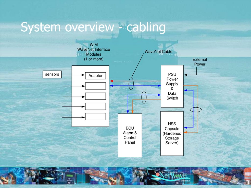
System overview - cablingWIM
WaveNet Interface
Modules
(1 or more)
sensors
WaveNet Cable
External
Power
PSU
Power
Supply
&
Data
Switch
Adaptor
BCU
Alarm &
Control
Panel
HSS
Capsule
(Hardened
Storage
Server)
13. System overview – daisy chaining
WIMWaveNet Interface
Modules
(1 or more)
NMEA
WaveNet Cable
External
Power
Adaptor
PSU
Power
Supply
&
Data
Switch
Adaptor
100
meters
max
Radar
Analogue
Digital
Microphones
NMEA
VHF/mics
Gyro
Log
Analogue
14. System overview - mixing
WIMWaveNet Interface
Modules
(1 or more)
NMEA
WaveNet Cable
External
Power
Adaptor
PSU
Power
Supply
&
Data
Switch
Adaptor
100
meters
max
Radar
Analogue
Digital
Microphones
NMEA
VHF/mics
Gyro
Log
Analogue
15. System overview - NMEA multiplexing
BCUBridge Control Unit
NMEA
C
O
M
1
NMEA
C
O
M
2
WIM
WaveNet Interface
Module
NMEA
NMEA
NMEA
NMEA
NMEA
Multiplexer
NMEA
Adaptor
16. Components
17. Components – HSS characteristics
capsule
release
mechanism
deckmount with
integrated CPU
Fully meets IMO Resolution A.861(20) and all applicable
Safety Of Life At Sea (SOLAS) Regulations.
Fully compliant to IEC 61996 Shipborne Voyage Data
Recorder Standard.
Records a minimum of 12 hours of voyage data: bridge
audio, VHF communications audio, radar, and NMEA 0183
serial data channels (IEC61162).
Single wire Power and high speed (100BaseT) Ethernet
communications.
Simplified (IMO mandated) annual maintenance routines
Reliable solid state recording (2+ years data retention
unpowered).
Fitted with an acoustic underwater location beacon operating
in the frequency band of 25 kHz to 50 kHz with a battery life
of at least 30 days, which meets SAE AS 8045.
Tamper resistant capsule design.
The final storage medium within the HSS retains the
recorded data for a period of at least two years, following
termination of recording, under the specified operational and
storage conditions.
18. Components – HSS memory
Exceptional read, write and erase performance
Built-in proprietary TrueFFS® technology for full hard-disk emulation,
high data reliability and maximum flash lifetime (28 years typical for
this VDR)
Data integrity with Error Detection Code/Error Correction Code
(EDC/ECC) based on a combination of BCH and Hamming algorithms
SuperMAP cryptographic engine to protected partitions
Data protected in hardware with digital signature: RSA with 64-byte
key
4-bit Error Detection Code/Error Correction Code (EDC/ECC), based on
a patented combination of BCH and Hamming code algorithms
Guaranteed data integrity even after power loss
Transparent bad-block management
Dynamic and static wear-levelling
Wear levelling algorithm that provides more than 5 million write / erase
cycles for reliable data storage over an extended per
19. Components – HSS Deckmount
20. Components – PSU characteristics
• bulkhead mounted cabinet, with the functionality to providepower to the system and all of its units
• serve as a data-interconnection device
• provides access to the VDR network
• serves as an auxiliary alarm device
• provides a remote alarm contact
• internal batteries
21. Components – PSU power
• Ship’s main power supply– 85-264 VAC (auto-sensing) and/or 24 V DC,
– built-in uninterruptible battery-back-up unit with batteries.
• At power failure, external switching in the ship should ensure
the emergency ship’s mains (110 V/220 V) is supplied to the
unit.
• AC supplies will normally be used to power the unit. However, in
the event of failure of the AC mains, this is detected by the PSU,
and the DC supply is automatically switched in to ensure
continued operation.
22. Components – PSU UPS
• Standard 12V batteriesBattery 1
Battery
Compartment
(remove 4 screws)
Battery 2
23. Components – PSU network ports
85-264 V AC24 V DC
WaveNet Ports
(Power over
Ethernet)
WN1
WN2
WN3
WN4
WN5
WN6
WN7
RJ-45
NET8
P
W
1
P
W
2
Remote Alarm
Contacts RA1
• The PSU has 8 network ports, 7 of which are
‘powered’ and may be connected to any of the other
VDR units (NW1-NW7).
• One RJ-45 connector (NET8) provides a transparent
link into the VDR network and is (optionally) used to
be connected to the ship’s network or a PC.
Network access
24. Components – PSU network ports
PSU – Network connections1
2
3
4
5
6
7
8
Ports 1- 7 WaveNet ports
Port 8 standard ethernet port
connect to Ground
25. Components – PSU network ports
PSU – Power and Alarm contacts85-264 VAC
+
24 VDC
-
NO - Normally Open
Common
NC - Normally Closed
Remote
alarm
units
26. Components – BCU characteristics
OptionalCompact Flash
Memory
Network
access
• console mountable
display & control unit
• primary userinteraction device.
• monitors the status
of the VDR and
functions as the
primary alarm unit.
• easy access and
control of specific
user-functions.
27. Components – BCU network access
• RJ-45 user-access Ethernet port to be connected to a(laptop/notebook) PC for system access (service and
maintenance) as well as data retrieval of recorded
data
28. Components – BCU interfacing
• NMEA ports– 4k8 Bd (GPS)
– 38k4 Bd (AIS)
COM2
NMEA
pin 3 Signal +
pin 5 Signal -
COM1
NMEA
pin 3 Signal +
pin 5 Signal -
NET
OUT
NET
IN
NC - Normally Closed
Common
NO - Normally Open
To remote Alarms
29. Components – WIM interfacing
MicrophonesDigital
Analogue
Radar
Adaptor
NETWORK
NMEA
Components – WIM interfacing
30. Components – Adaptor Modules
NW-4420
NW-4430
NW-4432
NW-4440
NW-4445
NW-4450
NW-4452
NW-4454
NW-4460
NW-4470
NW-4472
WaveNet 4-Channel Audio 3/4-CH MIC + 1/0 CH VHF
WaveNet 8-Channel Serial/NMEA adaptor
WaveNet 8-Channel Digital adaptor
Wavenet Radar Video adaptor VGA, SVGA, SXGA
Wavenet Radar video adaptor UXGA 1600x1200 (60hz)
Wavenet 4-Channel analogue adaptor 4-20 ma
Wavenet 4-Channel analogue adaptor -10v/+10v
Wavenet 4-Channel analogue adaptor 0-10v
Wavenet AIS adaptor 38.4k bd
Wavenet Compass adaptor / stepper
Wavenet Compass adaptor / synchro
NW-4480
Wavenet 200 ppm log adapter
31. NW-4420 WaveNet 4-Channel Audio 3/4-CH MIC + 1/0 CH VHF
Microphone Port xNW4420
AUDIO ADAPTOR
Recording Channel x
Microphone Port x
WIM
DSP
Microphone Port x
Recording Channel x
Microphone or VHF Port x
1
2
3
4
5
6
7
8
A
Audio Channel 2 (Microphone only) – Power 5 V DC + (Red)
Audio Channel 2 (Microphone only) – Audio IN + (Blue)
Audio Channel 2 (Microphone only) – Audio IN - (Green)
Audio Channel 2 (Microphone only) – Control (Yellow)
Audio Channel 1 (Microphone only) – Power 5 V DC + (Red)
Audio Channel 1 (Microphone only) – Audio IN + (Blue)
Audio Channel 1 (Microphone only) – Audio IN - (Green)
Audio Channel 1 (Microphone only) – Control (Yellow)
1
2
3
4
5
6
7
8
B
Audio Channel 4 (Microphone or VHF) – Power 5 V DC + (Red)
Audio Channel 4 (Microphone or VHF) – Audio IN + (Blue)
Audio Channel 4 (Microphone or VHF) – Audio IN - (Green)
Audio Channel 4 (Microphone or VHF) – Control (Yellow)
Audio Channel 3 (Microphone or VHF) – Power 5 V DC + (Red)
Audio Channel 3 (Microphone or VHF) – Audio IN + (Blue)
Audio Channel 3 (Microphone or VHF) – Audio IN - (Green)
Audio Channel 3 (Microphone or VHF) – Control (Yellow)
4 separate audio ports.
2 ports are configured as microphones
(fixed) and the other two ports may be
selected to be either VHF inputs or
microphone inputs.
Up to 4 audio recording channels (2 x
4420 adaptor) may be digitized and
compressed per WIM.
Provided the DIP switch in left in factory
Default (ON) all inputs are galvanically
separated.
This audio adaptor may be placed in any
free slot in any of the WaveNet Interface
Modules
32. NW4422 - Microphones
ControlSignal
Microphone Port 1
Microphone Port 2
Microphone Port 3
Microphone Port 4
Audio
Recording
Channel x
WIM
DSP
Recording
Channel x
to
network
33. NW4422 - Microphones
34. NW4422 – Audio - VHF
Rear View – DIP switches exampleFor channels 3 and 4 the DIP switches may be set to OFF to galvanically
separate the ports and enable them for VHF line input.
Please pay attention while to configuring (via the web-interface) the audio
channels to be recorded since the microphone test-signal should not be
activated on VHF inputs. In that event, an alarm will be generated since
the VDR system erroneously presumes a microphone to be present on that port!
For microphone
DIP-switch to ON (default)
For VHF
DIP-switch to OFF
Port 4
Microphone
Port 3
VHF line input
ON
OFF
35.
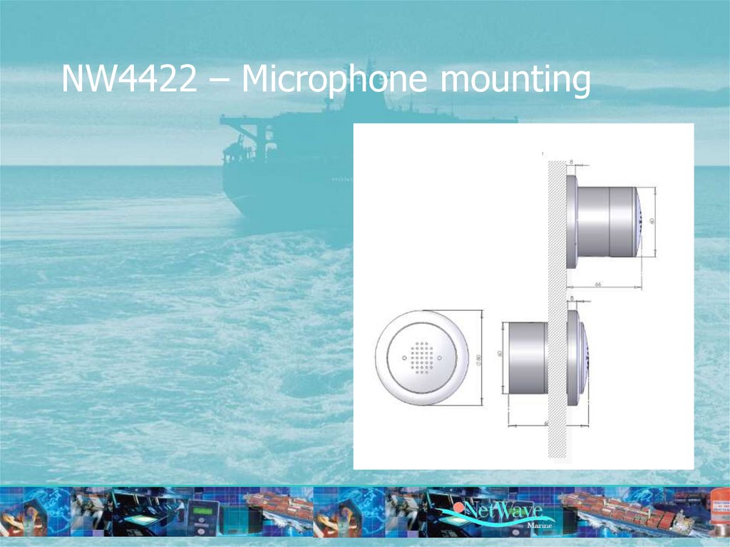
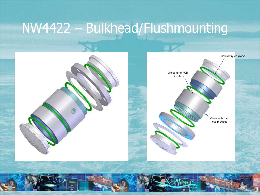
NW4422 – Microphone mounting36.
NW4422 – Bulkhead/FlushmountingCable entry via gland
Microphone PCB
inside
Close with blind
cap provided
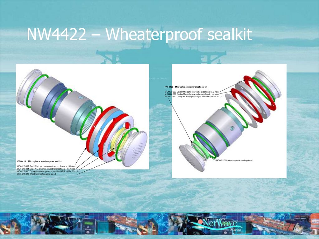
37.
NW4422 – Wheaterproof sealkitNW-4428
Microphone weatherproof seal kit
MC4422-302 Seal B Microphone weatherproof seal w. 3 holes
MC4422-301 Seal A Microphone weatherproof seal - no holes
MC4422-310 O-ring for water-proof Mylar film NBR 36624 35x1,2
NW-4428
Microphone weatherproof seal kit
MC4422-302 Seal B Microphone weatherproof seal w. 3 holes
MC4422-301 Seal A Microphone weatherproof seal - no holes
MC4422-310 O-ring for water-proof Mylar film NBR 36624 35x1,2
MC4422-320 Weatherproof sealing gland
MC4422-320 Weatherproof sealing gland
38. NW-4430 - WaveNet 8-Channel Serial/NMEA adaptor
NW4430SERIAL NMEA ADAPTOR
NMEA Port 1
Recording Channel x
NMEA Port 2
Recording Channel x
NMEA Port 3
Recording Channel x
NMEA Port 4
Recording Channel x
NMEA Port 5
Recording Channel x
NMEA Port 6
Recording Channel x
NMEA Port 7
Recording Channel x
NMEA Port 8
Recording Channel x
WIM
DSP
1
2
3
4
5
6
7
8
A
Channel 4 – Ground (-)
Channel 4 – Signal (+)
Channel 3 – Ground (-)
Channel 3 – Signal (+)
Channel 2 – Ground (-)
Channel 2 – Signal (+)
Channel 1 – Ground (-)
Channel 1 – Signal (+)
1
2
3
4
5
6
7
8
B
Channel 8 – Ground (-)
Channel 8 – Signal (+)
Channel 7 – Ground (-)
Channel 7 – Signal (+)
Channel 6 – Ground (-)
Channel 6 – Signal (+)
Channel 5 – Ground (-)
Channel 5 – Signal (+)
microprocessor adapter
8 serial NMEA input
ports (separate
recording channels)
inputs are galvanically
separated
maximum of 64 NMEA
channels
39. NW-4432 WaveNet 8-Channel Digital adaptor
NW-4432NW4432
DIGITAL DISCRETE
ADAPTOR
1
2
3
4
5
6
7
WaveNet 8-Channel Digital adaptor
Digital I/O 1
Recording Channel x
Digital I/O 2
Recording Channel x
Digital I/O 3
Recording Channel x
Digital I/O 4
Recording Channel x
Digital I/O 5
Recording Channel x
Digital I/O 6
Recording Channel x
Digital I/O 7
Recording Channel x
Digital I/O 8
Recording Channel x
WIM
DSP
8
A
Channel 4 – Negative (-)
Channel 4 – Positive (+)
Channel 3 – Negative (-)
Channel 3 – Positive (+)
Channel 2 – Negative (-)
Channel 2 – Positive (+)
Channel 1 – Negative (-)
Channel 1 – Positive (+)
1
2
3
4
5
6
7
8
B
Channel 8 – Negative (-)
Channel 8 – Positive (+)
Channel 7 – Negative (-)
Channel 7 – Positive (+)
Channel 6 – Negative (-)
Channel 6 – Positive (+)
Channel 5 – Negative (-)
Channel 5 – Positive (+)
8 digital inputs to which
digital (on/off) signals
can be connected.
All inputs are galvanically
separated from the VDR
and from one another.
active between 10 VDC
and 36 VDC
inactive below 5 VDC
10-36 VDC or connect to
unpowered sensor
maximum of 4 NW4432
adaptors, therefore 32
discrete recording
channels (per WIM)
40. NW-4440 WaveNet Radar Video Adaptor VGA, SVGA, SXGA NW-4445 Wavenet Radar Video adaptor UXGA 1600x1200
NW4440Radar Video Adaptor
Radar Video
IMPORTANT
This 2 slot adaptor
may only be
positioned at the
(most right)
Number 4&5 slot
positions of the
WIM
1
TMDS Data2
2
TMDS Data2+
3
TMDS Data2/4 Shield
4
TMDS Data4
5
TMDS Data4+
6
DDC Clock [SCL]
7
DDC Data [SDA]
8
Analog vertical sync
9
TMDS Data1
10 TMDS Data1+
11 TMDS Data1/3 Shield
12 TMDS Data3
13 TMDS Data3+
14 +5 V Power
15 Ground(for +5 V)
16 Hot Plug Detect
17 TMDS Data0
18 TMDSData0+
19 TMDS Data0/5 Shield
20 TMDS Data5
21 TMDS Data5+
22 TMDS Clock Shield
23 TMDS Clock +
24 TMDS Clock
C1 Analog Red
C2 Analog Green
C3 Analog Blue
C4 Analog Horizontal Sync
C5 Ana log GND Return: (analog R, G, B)
Recording Channel x
WIM
DSP
41. NW-4450 Wavenet 4-Channel analogue adaptor 4-20 mA
NW44504 CH ANALOGUE (mA)
ADAPTOR
Analogue 4-20 mA port 1
Recording Channel x
Analogue 4-20 mA port 2
Recording Channel x
WIM
DSP
Analogue 4-20 mA port 3
Recording Channel x
Analogue 4-20 mA port 4
Recording Channel x
to
network
1
2
3
4
5
6
7
8
A
INPUT Channel 4 + (positive)
INPUT Channel 4 - (negative)
INPUT Channel 3 + (positive)
INPUT Channel 3 - (negative)
INPUT Channel 2 + (positive)
INPUT Channel 2 – (negative)
INPUT Channel 1 + (positive)
INPUT Channel 1 – (negative)
microprocessor
based
wet or dry contact
interface.
4 input channels
per adaptor
accept 4-20mA
complete optoisolation
full DC-DC electrical
isolation in its input
power supply.
4 analogue
adaptors
16 channels per
WIM
42. NW-4452 Wavenet 4-Channel analogue adaptor -10v/+10v
NW44524 CH ANALOGUE
(-10/+10 V) ADAPTOR
Analogue -10 to + 10 V DC port 1
Recording Channel x
Analogue -10 to + 10 V DC port 2
Recording Channel x
Analogue -10 to + 10 V DC port 3
Recording Channel x
Analogue -10 to + 10 V DC port 4
Recording Channel x
WIM
DSP
to
network
1
2
3
4
5
6
7
8
A
INPUT Channel 4 + (positive)
INPUT Channel 4 - (negative)
INPUT Channel 3 + (positive)
INPUT Channel 3 - (negative)
INPUT Channel 2 + (positive)
INPUT Channel 2 – (negative)
INPUT Channel 1 + (positive)
INPUT Channel 1 – (negative)
microprocessor based
interface.
4 input channels per
adaptor,
-10 V to +10V.
complete opto-isolation
from the source.
full DC-DC electrical
isolation
43. NW-4454 Wavenet 4-Channel analogue adaptor 0-10v
NW44544 CH ANALOGUE
(0-10 V) ADAPTOR
Analogue 0-10 V DC port 1
Recording Channel x
Analogue 0-10 V DCport 2
Recording Channel x
WIM
DSP
1
2
3
4
5
6
7
Analogue 0-10 V DCport 3
Recording Channel x
Analogue 0-10 V DC port 4
Recording Channel x
8
A
INPUT Channel 4 + (positive)
INPUT Channel 4 - (negative)
INPUT Channel 3 + (positive)
INPUT Channel 3 - (negative)
INPUT Channel 2 + (positive)
INPUT Channel 2 – (negative)
INPUT Channel 1 + (positive)
INPUT Channel 1 – (negative)
to
network
• microprocessor based
interface.
• 4 input channels per
adaptor
• 0 V to +10V.
• complete optoisolation from the
source.
• full DC-DC electrical
isolation in its input
power supply
44. NW-4460 Wavenet AIS adaptor 38.4k bd
NW4460AIS ADAPTOR
AIS NMEA (38k4 Bd)
Recording Channel x
WIM
DSP
to
network
• converts serial AIS data (at 38k4 Baud)
• also possible to feed the AIS data through
one of the serial ports on the Bridge
Control Unit into the VDR system.
• 1 AIS adaptor may be connected into any
one WIM
1
2
3
4
5
6
7
8
A
AIS (NMEA-2) TX- (38.4 K Baud)
AIS (NMEA-2) TX+ (38.4 K Baud)
45. WAM 4470+80 – Wavenet Gyro Compass Adaptors
NW4470GYRO STEPPER ADAPTOR
1
2
3
4
5
6
7
Gyro Compass
8
S1
S2
Recording Channel x
COM
COM1
to
network
• Microprocessor
based
gyrocompass
interfaces
• actual course
must be readjusted
S3
NC NC NC
WIM
DSP
• rtm
46. Functions & Features
Functions & Features47. Functions & Features
Functions & Features• Data Time Stamping
• Resistance to Tampering
• Data Storage and Format
• Data Blocks
48. Functions – Data block
Type approval authority and reference.
IMO vessel identification number.
Software version(s) used.
Microphone locations and recording port allocation.
VHF communications - which VHF(s) recorded.
Date and time - from which source obtained.
Ship’s position - from which electronic position-fixing system
(EPFS) obtained and relative position on the vessel.
• Other data inputs - identification of which equipment is
supplying recorded data
• Automatic insertion of date and time of last amendment.
• Integrity of Recorded Data
49. Functions - System Integrity
• Power supply• Record function / channels
• Bit error rate / memory
• Microphone functionality
50. Functions – Auto Configuring
• Interface Modules• Adaptors
• Channels
51. Installation
52. Installation
• Cabling according to Pre-installationSurvey
• Mechanical
– Mounting brackets
– Gland slots
– Connectors
53. Single Line Drawing
54. Configuration
55. Configuration
• Browser based Network connection– Via BCU or PSU network ports
– Ethernet cable type is ‘straight thru’
• SUPPLIED
– Fixed IP address of server
• 192.168.2.50
– Fault finding: extensive in manual
• Home Page
Step
1
56. Configuration - Home
57. Configuration - Password
Step2
58. Configuration – Data block
StepConfiguration – Data block
3
59. Configuration – Check Units
Step4
60. Configuration – check Interfaces
Step5
61. Configuration – check PSU
Step6
62. Configuration – check BCU
Step7
63. Configuration – check HSS
Step8
64. Enable Recording Channels
StepEnable Recording Channels
9
65. Configure Recording Channels - Audio
StepConfigure Recording Channels - Audio
10
66.
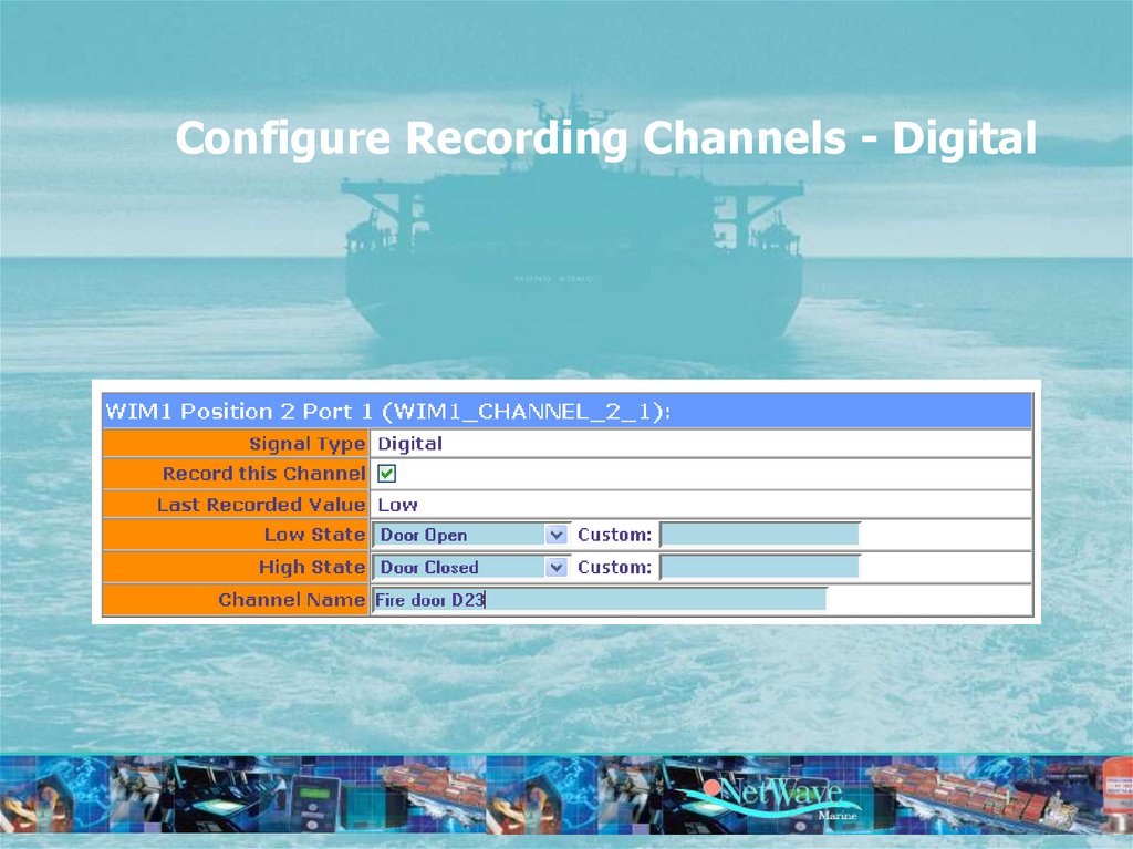
Configure Recording Channels - Digital67.
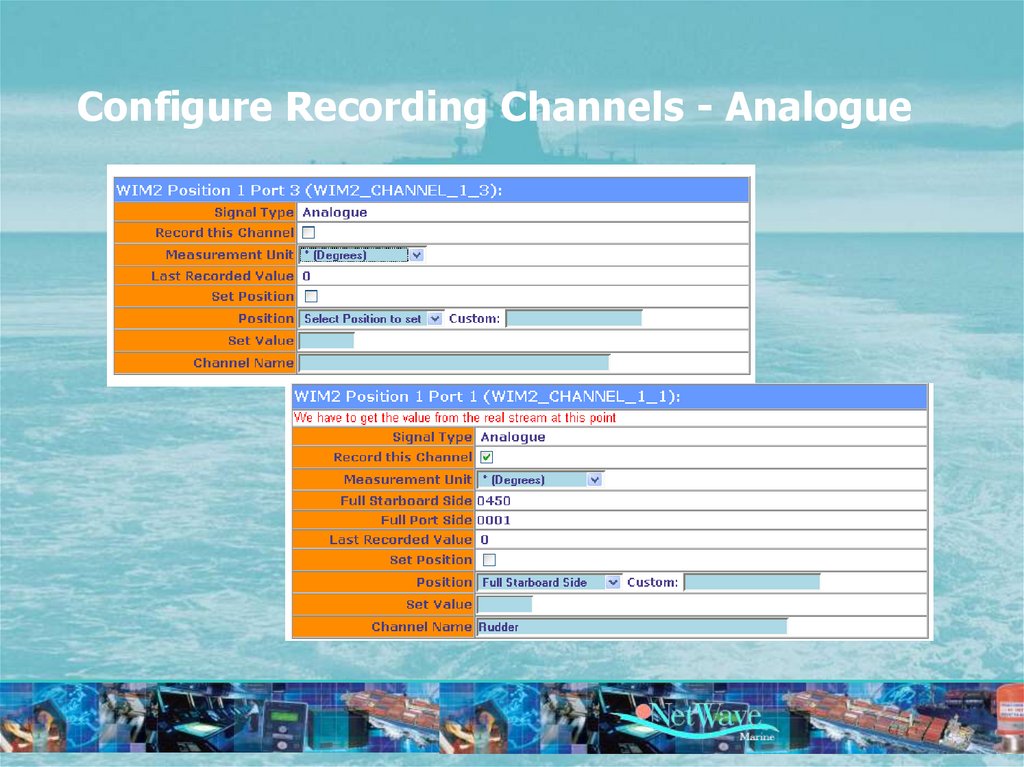
Configure Recording Channels - Analogue68. Configure Recording Channels - Radar
69. Configure Recording Channels - Radar
70. Alarms, Log, Events
71. Alarms
• Power (lost) Alarm• Bit error rate
• Recording Failure (read after write)
• Microphone errors (not detected)
• Radar video data (lost)
• Temperature overshoot
• Units or sensors disconnected
• Time reference lost
• Position and/or Heading lost
72. Logging & Monitoring
Logging & Monitoring73. Event Log
74. Server Log
75. Access Log
76. Security
77. Security
• IMO regulations require the VDR to be protectedagainst tampering and to administer all access and
configuration attempts. This implemented is as
follows;
– Everyone has access the “HOME’ and ‘Status’ pages without
providing any password.
– The pages Configuration are accessible by providing the
Installer password, which defaults to ‘Rotterdam’.
– The Pages ‘Devices’ and ‘Channels’ are accessible by
providing a second level password which is issued at the
time of installation
– Any higher level Control functions may only be performed
after consultation with the factory.