 electronics
Similar presentations:


")
")


Counter Circuits and VHDL State Machines Lecture 10 Digital Electronics
1.
Counter Circuits andVHDL State Machines
Lecture 10
Digital Electronics
2.
Course MaterialsAll needed Software and course materials will
be located on Canvas.
◻ Materials that are used in this slides are taken
from the textbook “Digital Electronics A
Practical Approach with VHDL” by William
Kleitz
◻
3.
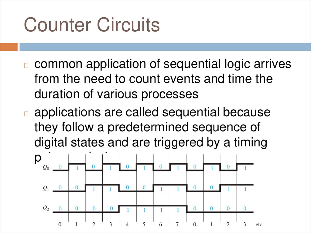
Counter Circuitscommon application of sequential logic arrives
from the need to count events and time the
duration of various processes
◻ applications are called sequential because
they follow a predetermined sequence of
digital states and are triggered by a timing
pulse or clock
◻
4.
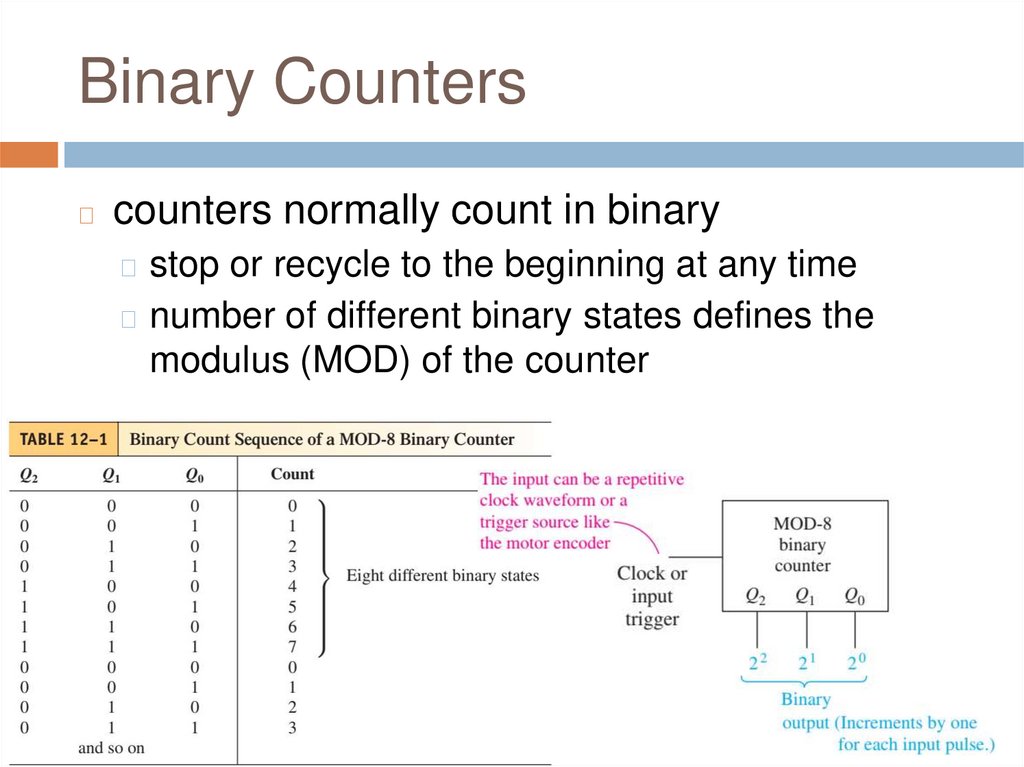
Binary Counters◻
counters normally count in binary
◻ stop or recycle to the beginning at any time
◻ number of different binary states defines the
modulus (MOD) of the counter
5.
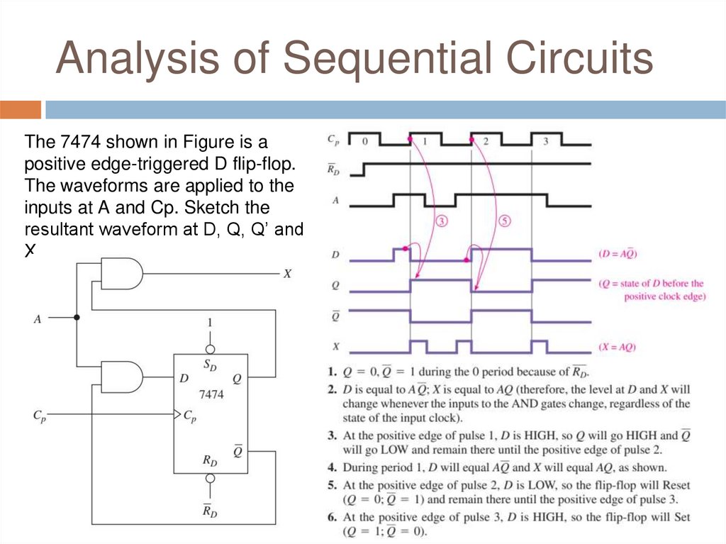
Analysis of Sequential CircuitsThe 7474 shown in Figure is a
positive edge-triggered D flip-flop.
The waveforms are applied to the
inputs at A and Cp. Sketch the
resultant waveform at D, Q, Q’ and
X.
6.
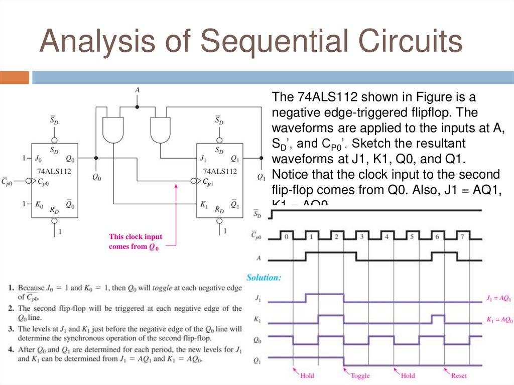
Analysis of Sequential CircuitsThe 74ALS112 shown in Figure is a
negative edge-triggered flipflop. The
waveforms are applied to the inputs at A,
SD’, and CP0’. Sketch the resultant
waveforms at J1, K1, Q0, and Q1.
Notice that the clock input to the second
flip-flop comes from Q0. Also, J1 = AQ1,
K1 = AQ0.
7.
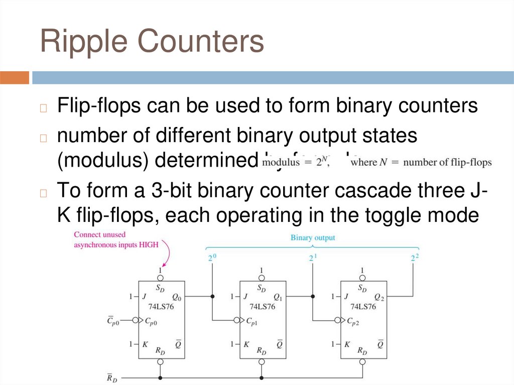
Ripple CountersFlip-flops can be used to form binary counters
◻ number of different binary output states
(modulus) determined by formula:
◻ To form a 3-bit binary counter cascade three JK flip-flops, each operating in the toggle mode
◻
8.
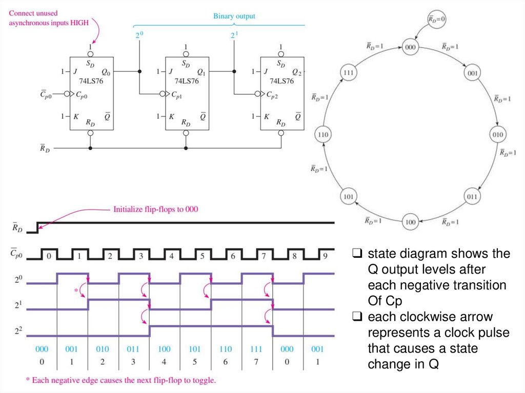
❑ state diagram shows theQ output levels after
each negative transition
Of Cp
❑ each clockwise arrow
represents a clock pulse
that causes a state
change in Q
9.
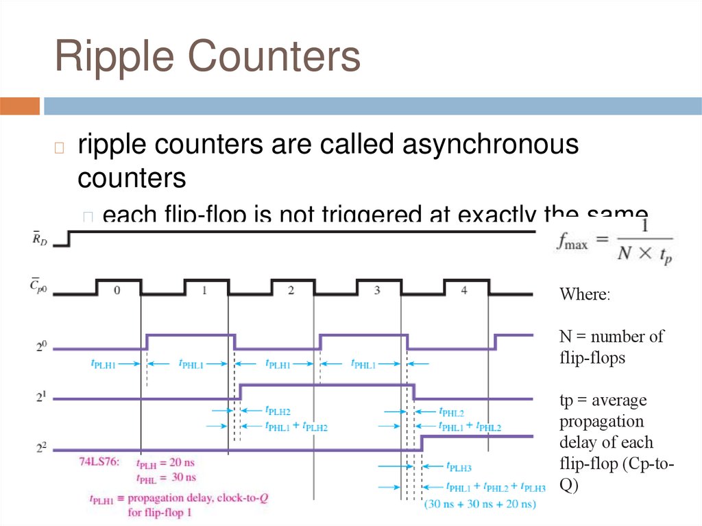
Ripple Counters◻
ripple counters are called asynchronous
counters
◻ each flip-flop is not triggered at exactly the same
time
Where:
N = number of
flip-flops
tp = average
propagation
delay of each
flip-flop (Cp-toQ)
10.
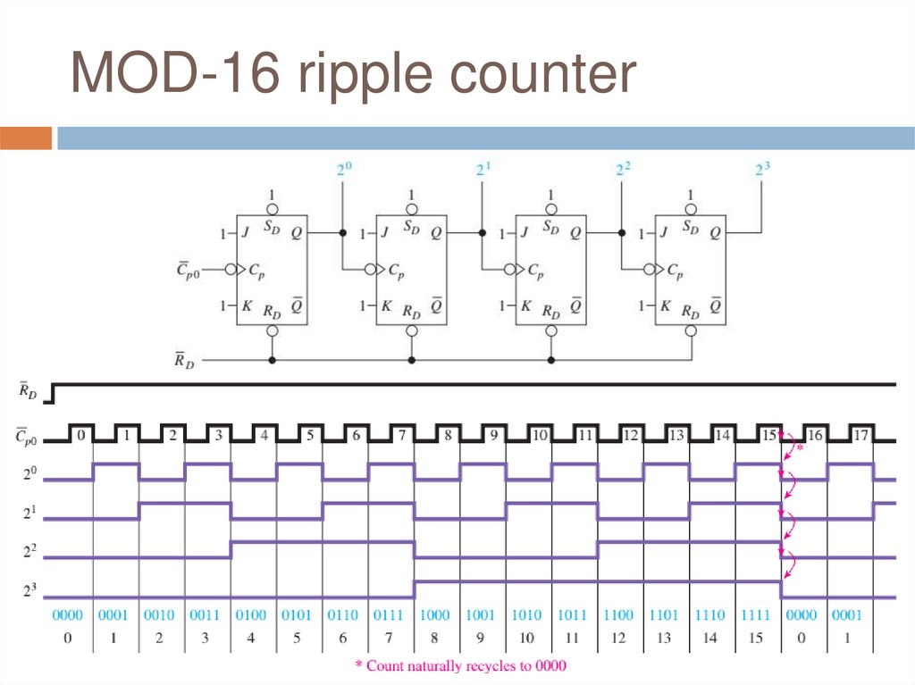
MOD-16 ripple counter11.
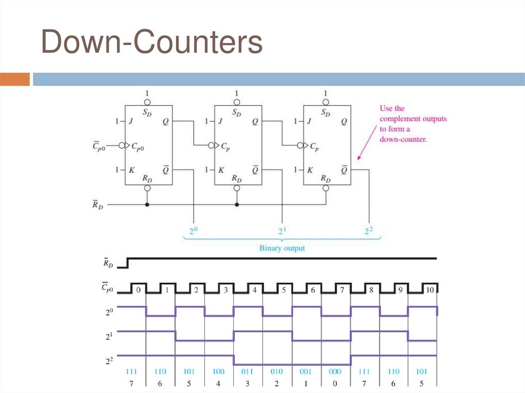
Down-Counters12.
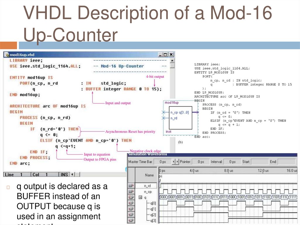
VHDL Description of a Mod-16Up-Counter
LIBRARY ieee;
USE ieee.std_logic_1164.ALL;
ENTITY L9_MOD16UP IS
PORT(
n_cp, n_rd : IN std_logic;
q
: BUFFER integer RANGE 0 TO 15
);
END L9_MOD16UP;
ARCHITECTURE arc OF L9_MOD16UP IS
BEGIN
PROCESS (n_cp, n_rd)
BEGIN
IF (n_rd = '0') THEN
q <= 0;
ELSIF (n_cp'EVENT AND n_cp = '0') THEN
q <= q + 1;
END IF;
END PROCESS;
END arc;
◻
q output is declared as a
BUFFER instead of an
OUTPUT because q is
used in an assignment
13.
Review Questions1.
2.
3.
When analyzing digital circuits containing basic
gates combined with sequential logic like flipflops, you must remember that gate outputs
can change at any time, whereas sequential
logic only changes at the active clock edges.
True or false?
For a binary ripple counter to function properly,
all J and K inputs must be tied ___________
(HIGH, LOW), and all SD’ and RD’ inputs must
be tied ___________ (HIGH, LOW) to count?
How can a ripple up-counter be converted to a
14.
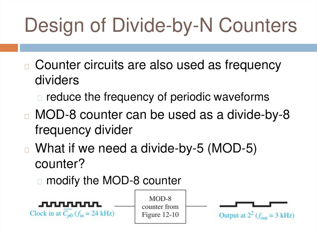
Design of Divide-by-N Counters◻
Counter circuits are also used as frequency
dividers
◻ reduce the frequency of periodic waveforms
MOD-8 counter can be used as a divide-by-8
frequency divider
◻ What if we need a divide-by-5 (MOD-5)
counter?
◻
◻ modify the MOD-8 counter
◻ when it reaches 5 (101) all flip-flops will be Reset
15.
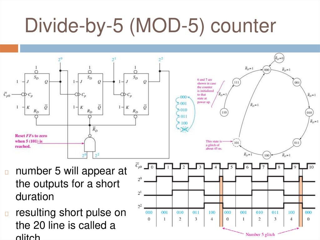
Divide-by-5 (MOD-5) counternumber 5 will appear at
the outputs for a short
duration
◻ resulting short pulse on
the 20 line is called a
◻
16.
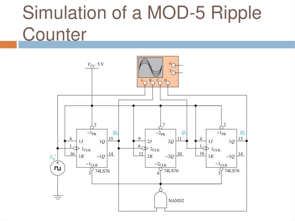
Simulation of a MOD-5 RippleCounter
17.
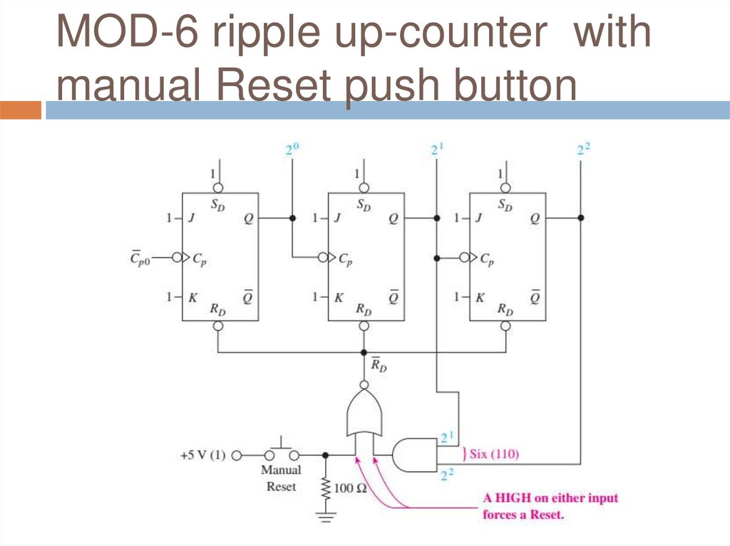
MOD-6 ripple up-counter withmanual Reset push button
18.
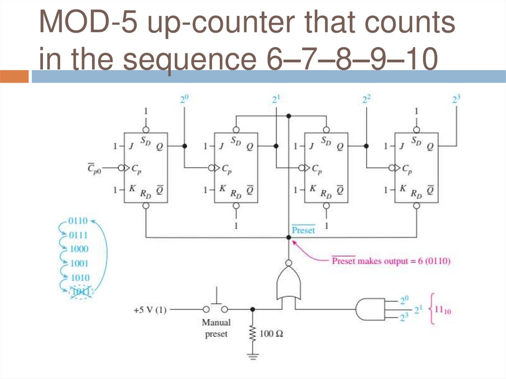
MOD-5 up-counter that countsin the sequence 6–7–8–9–10
19.
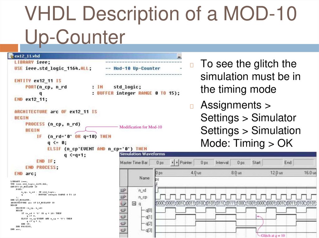
VHDL Description of a MOD-10Up-Counter
To see the glitch the
simulation must be in
the timing mode
◻ Assignments >
Settings > Simulator
Settings > Simulation
Mode: Timing > OK
◻
LIBRARY ieee;
USE ieee.std_logic_1164.ALL;
ENTITY L9_MOD10UP IS
PORT(
n_cp, n_rd : IN std_logic;
q
: BUFFER integer RANGE 0 TO 15
);
END L9_MOD10UP;
ARCHITECTURE arc OF L9_MOD10UP IS
BEGIN
PROCESS (n_cp, n_rd)
BEGIN
IF (n_rd = '0' OR q = 10) THEN
q <= 0;
ELSIF (n_cp'EVENT AND n_cp = '0') THEN
q <= q + 1;
END IF;
END PROCESS;
END arc;
20.
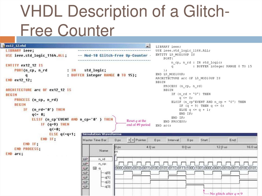
VHDL Description of a GlitchFree CounterLIBRARY ieee;
USE ieee.std_logic_1164.ALL;
ENTITY L9_MOD10UP IS
PORT(
n_cp, n_rd : IN std_logic;
q
: BUFFER integer RANGE 0 TO 15
);
END L9_MOD10UP;
ARCHITECTURE arc OF L9_MOD10UP IS
BEGIN
PROCESS (n_cp, n_rd)
BEGIN
IF (n_rd = '0') THEN
q <= 0;
ELSIF (n_cp'EVENT AND n_cp = '0') THEN
IF (q = 9) THEN q <= 0;
ELSE q <= q + 1;
END IF;
END IF;
END PROCESS;
END arc;
21.
Review Questions1.
2.
3.
To convert a 4-bit MOD-16 counter to a
MOD-12 counter, the flipflops must be Reset
when the counter reaches the number
_______ (11, 12, 13)?
A MOD-16 counter can function as a divideby-16 frequency divider by taking the output
from the ___________ (20, 21, 22, 23) output?
The Manual Reset push-button circuitry used
in the MOD-N counters is connected to NOR
gate. True / False?
22.
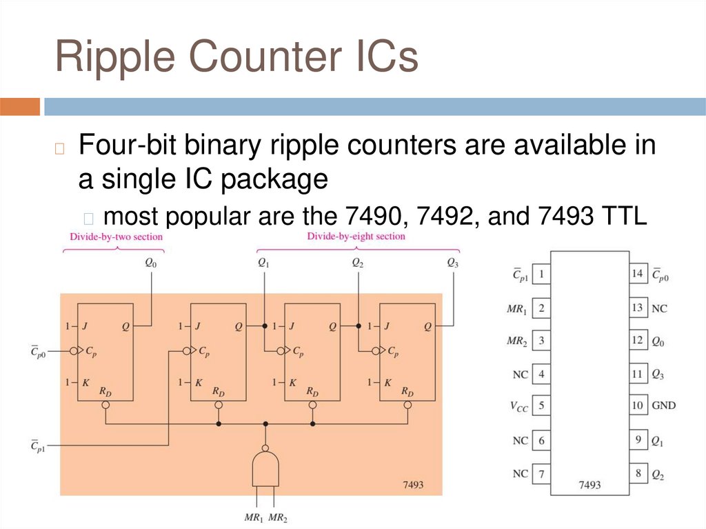
Ripple Counter ICs◻
Four-bit binary ripple counters are available in
a single IC package
◻ most popular are the 7490, 7492, and 7493 TTL
ICs
23.
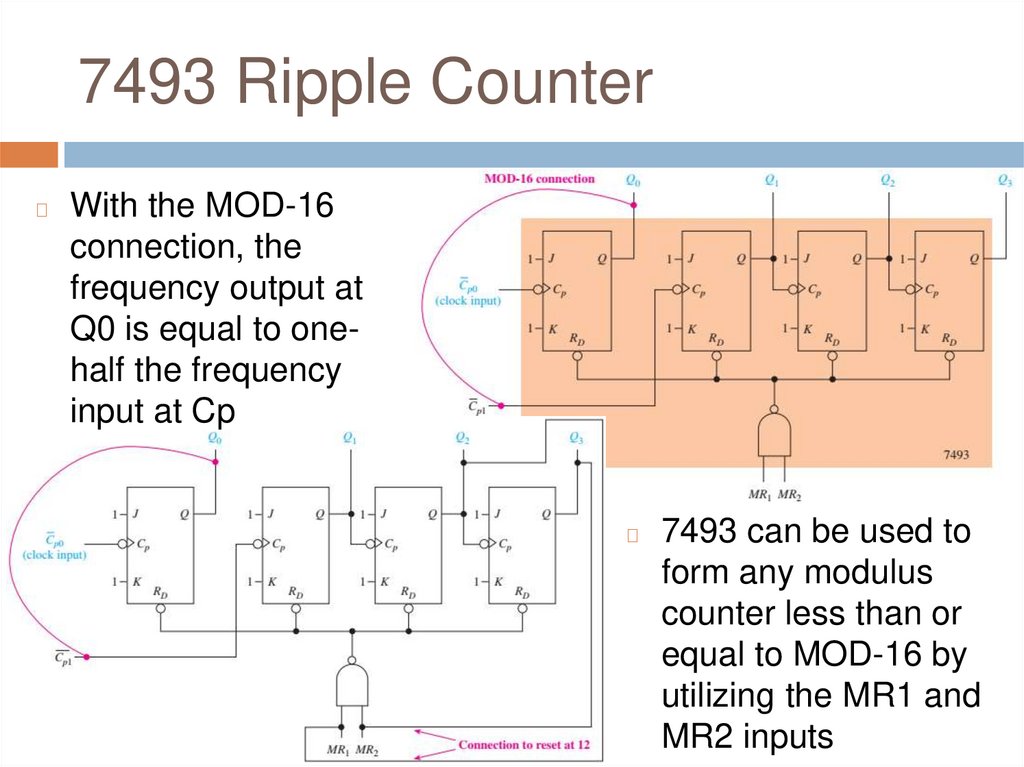
7493 Ripple Counter◻
With the MOD-16
connection, the
frequency output at
Q0 is equal to onehalf the frequency
input at Cp
◻
7493 can be used to
form any modulus
counter less than or
equal to MOD-16 by
utilizing the MR1 and
MR2 inputs
24.
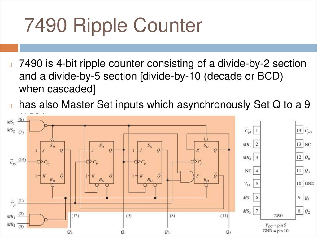
7490 Ripple Counter7490 is 4-bit ripple counter consisting of a divide-by-2 section
and a divide-by-5 section [divide-by-10 (decade or BCD)
when cascaded]
◻ has also Master Set inputs which asynchronously Set Q to a 9
(1001)
◻
25.
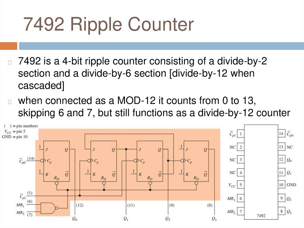
7492 Ripple Counter7492 is a 4-bit ripple counter consisting of a divide-by-2
section and a divide-by-6 section [divide-by-12 when
cascaded]
◻ when connected as a MOD-12 it counts from 0 to 13,
skipping 6 and 7, but still functions as a divide-by-12 counter
◻
26.
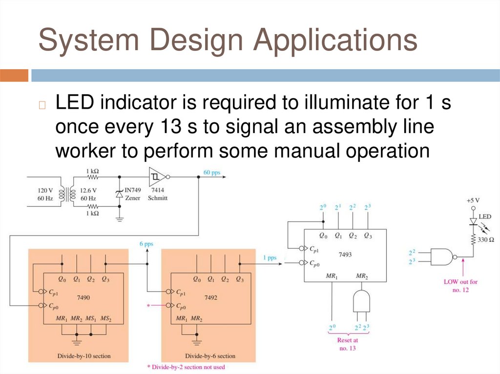
System Design Applications◻
LED indicator is required to illuminate for 1 s
once every 13 s to signal an assembly line
worker to perform some manual operation
27.
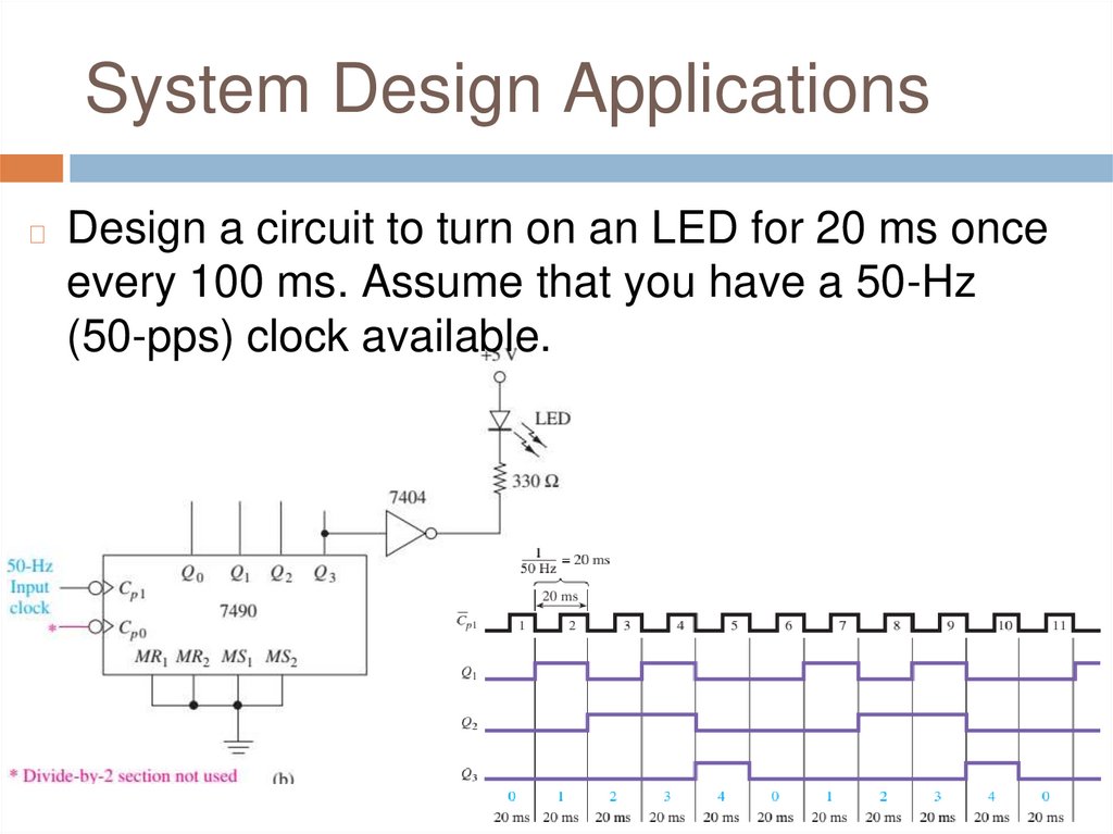
System Design Applications◻
Design a circuit to turn on an LED for 20 ms once
every 100 ms. Assume that you have a 50-Hz
(50-pps) clock available.
28.
System Design Applications◻
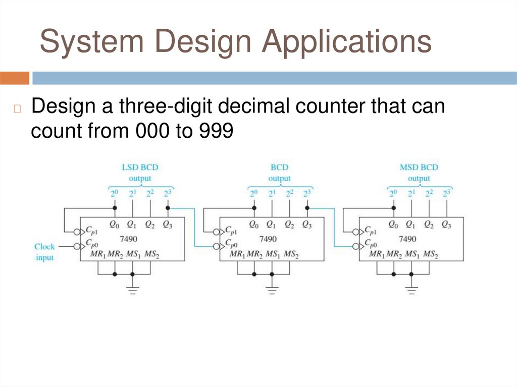
Design a three-digit decimal counter that can
count from 000 to 999
29.
System Design Applications◻
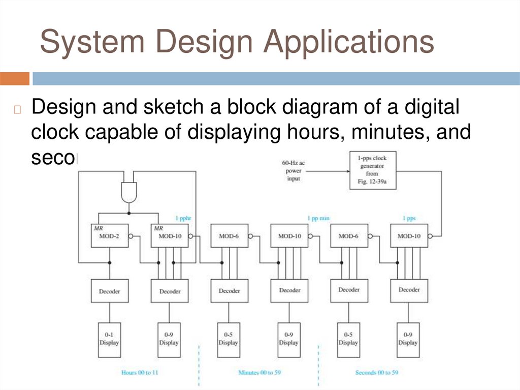
Design and sketch a block diagram of a digital
clock capable of displaying hours, minutes, and
seconds.
30.
System Design Applications◻
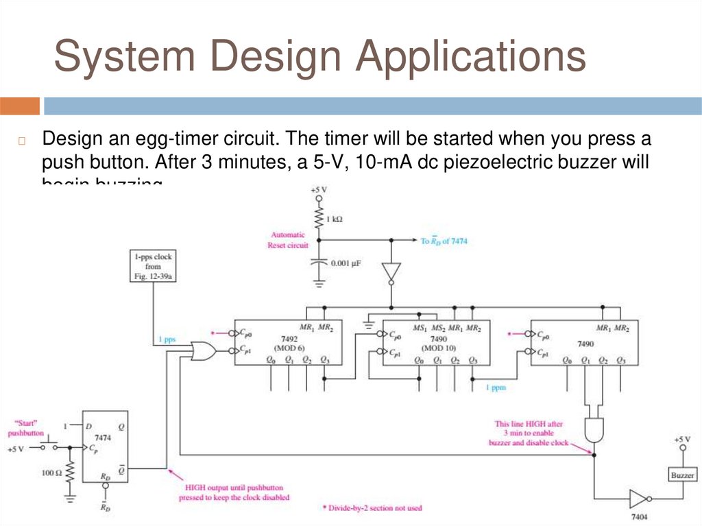
Design an egg-timer circuit. The timer will be started when you press a
push button. After 3 minutes, a 5-V, 10-mA dc piezoelectric buzzer will
begin buzzing
31.
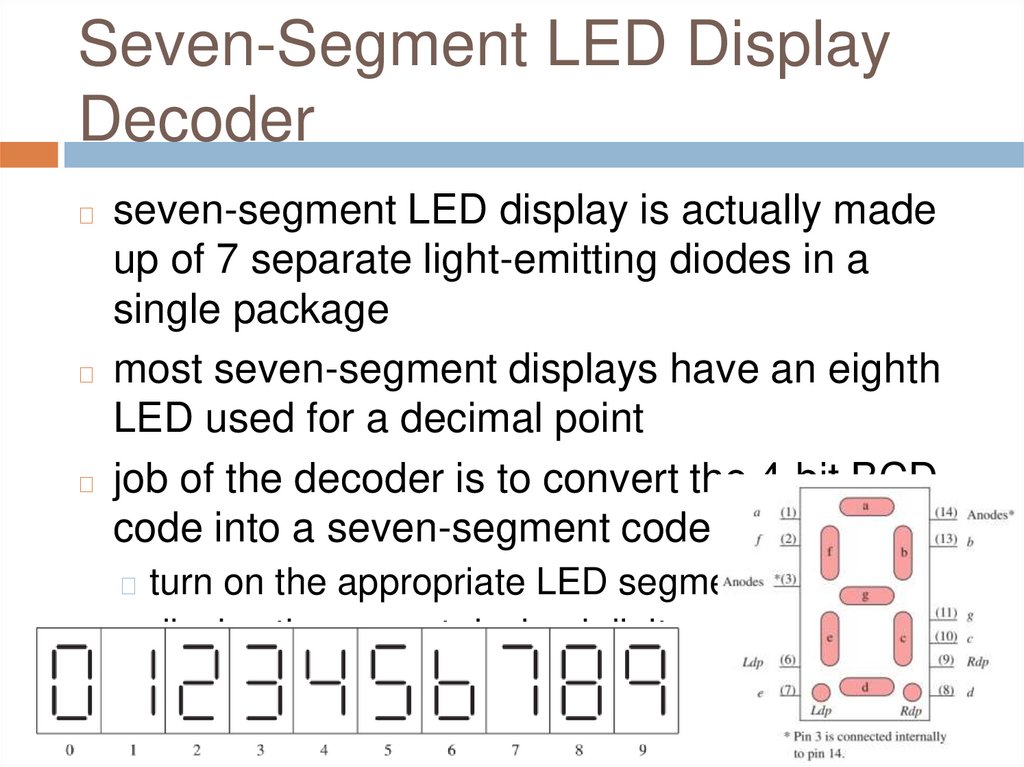
Seven-Segment LED DisplayDecoder
seven-segment LED display is actually made
up of 7 separate light-emitting diodes in a
single package
◻ most seven-segment displays have an eighth
LED used for a decimal point
◻ job of the decoder is to convert the 4-bit BCD
code into a seven-segment code
◻
◻ turn on the appropriate LED segments
◻ display the correct decimal digit
32.
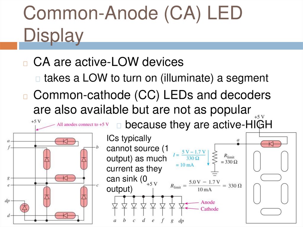
Common-Anode (CA) LEDDisplay
◻
CA are active-LOW devices
◻ takes a LOW to turn on (illuminate) a segment
◻
Common-cathode (CC) LEDs and decoders
are also available but are not as popular
◻ because they are active-HIGH
ICs typically
cannot source (1
output) as much
current as they
can sink (0
output)
33.
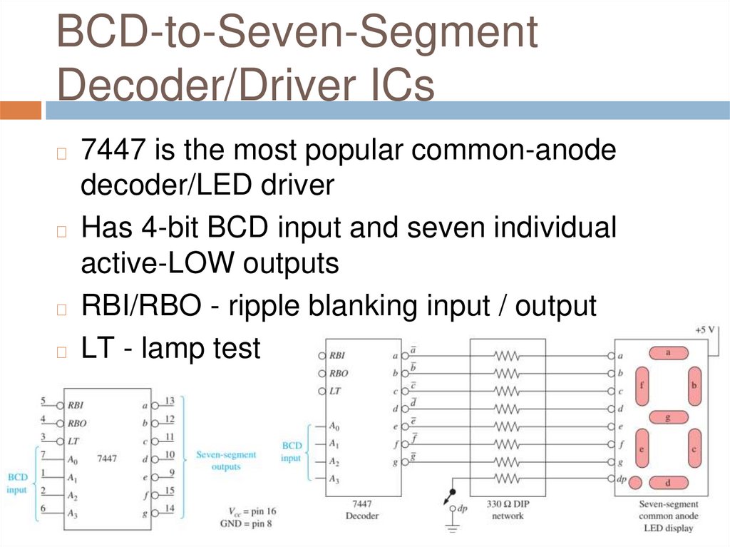
BCD-to-Seven-SegmentDecoder/Driver ICs
7447 is the most popular common-anode
decoder/LED driver
◻ Has 4-bit BCD input and seven individual
active-LOW outputs
◻ RBI/RBO - ripple blanking input / output
◻ LT - lamp test
◻
34.
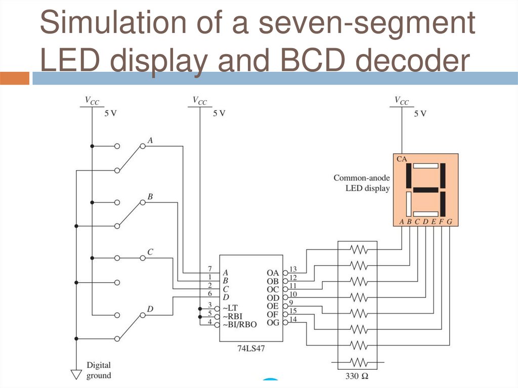
Simulation of a seven-segmentLED display and BCD decoder
35.
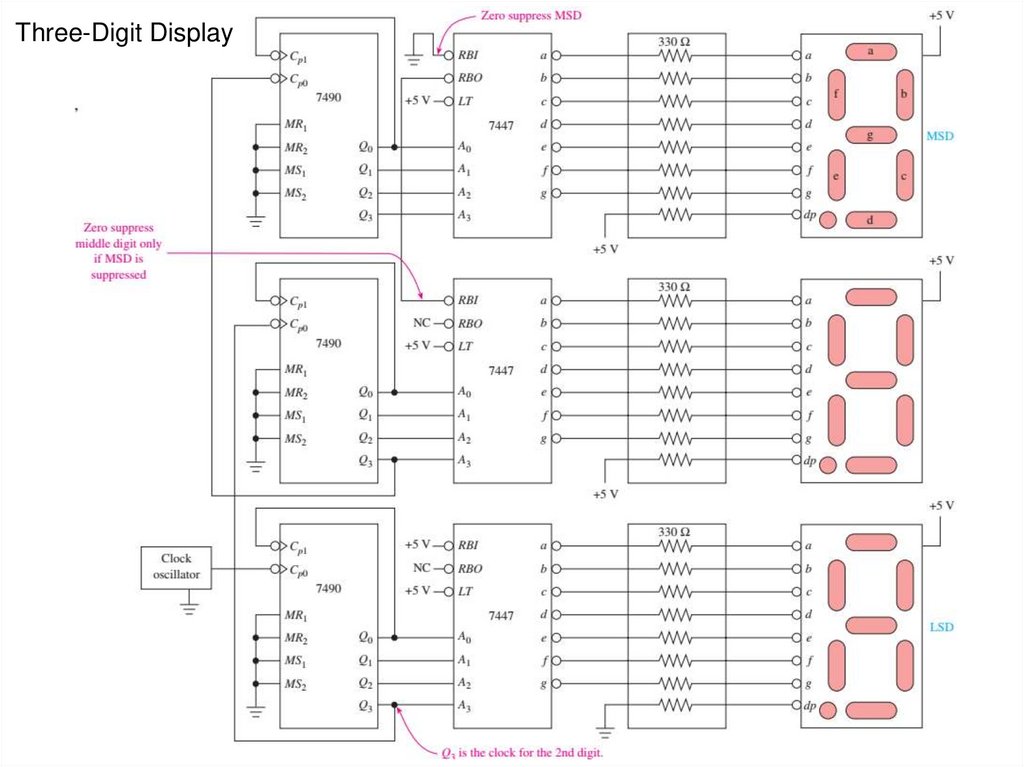
Three-Digit Display36.
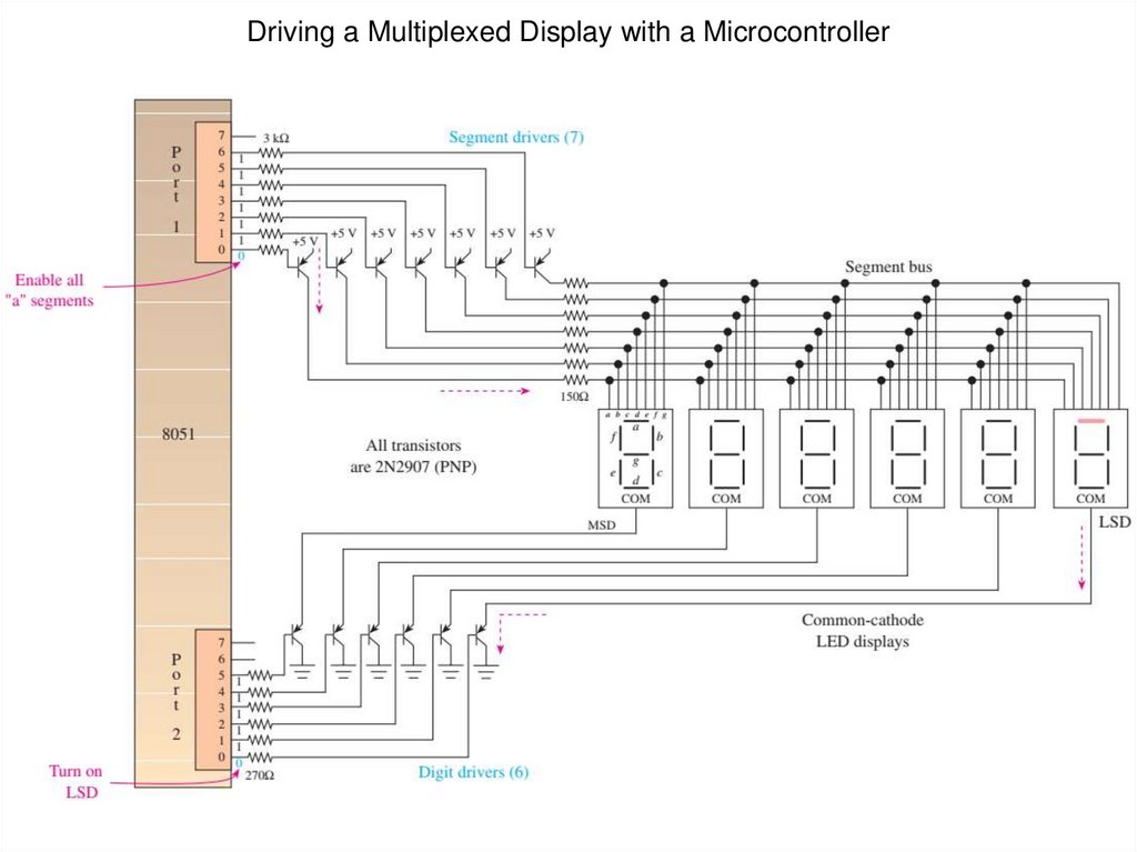
Driving a Multiplexed Display with a Microcontroller37.
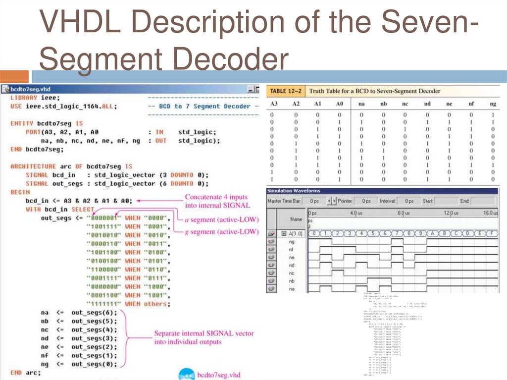
VHDL Description of the SevenSegment DecoderLIBRARY ieee;
USE ieee.std_logic_1164.ALL;
ENTITY L10_BCDTO7SEG IS
PORT(
A3, A2, A1, A0
: IN std_logic;
na, nb, nc, nd, ne, nf, ng : OUT std_logic
);
END L10_BCDTO7SEG;
ARCHITECTURE arc OF L10_BCDTO7SEG IS
SIGNAL bcd_in
: std_logic_vector(3 DOWNTO 0);
SIGNAL out_segs : std_logic_vector(6 DOWNTO 0);
BEGIN
bcd_in <= A3 & A2 & A1 & A0;
WITH bcd_in SELECT out_segs <=
"0000001" WHEN "0000",
"1001111" WHEN "0001",
"0010010" WHEN "0010",
"0000110" WHEN "0011",
"1001100" WHEN "0100",
"0100100" WHEN "0101",
"1100000" WHEN "0110",
"0001111" WHEN "0111",
"0000000" WHEN "1000",
"0001100" WHEN "1001",
"1111111" WHEN OTHERS;
na <= out_segs(6);
nb <= out_segs(5);
nc <= out_segs(4);
nd <= out_segs(3);
ne <= out_segs(2);
nf <= out_segs(1);
ng <= out_segs(0);
END arc;
38.
Review Questions1.
2.
3.
4.
The 7447 IC is used to convert ___________
data into _______ data for common________ LEDs?
Why are series resistors required when
driving a seven-segment LED display?
List the active segments, by letter, that form
the digit 5 on a seven-segment display?
Seven-segment displays are either common
anode or common cathode. What does this
mean?
39.
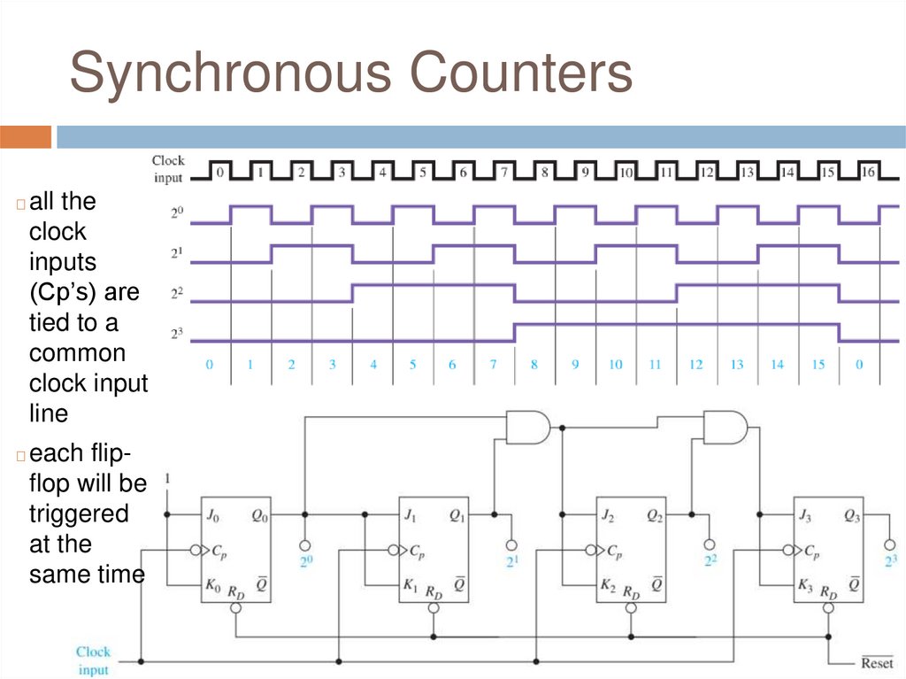
Synchronous Counters◻
all the
clock
inputs
(Cp’s) are
tied to a
common
clock input
line
◻
each flipflop will be
triggered
at the
same time
40.
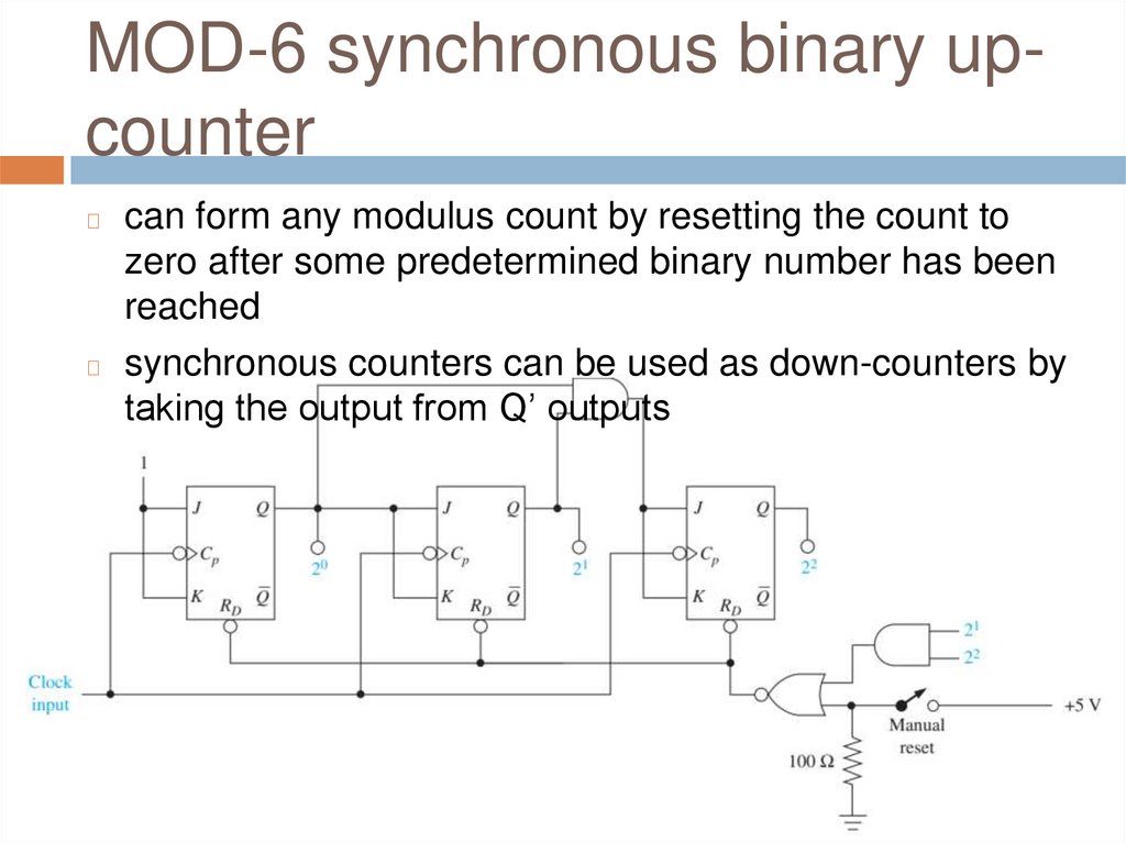
MOD-6 synchronous binary upcountercan form any modulus count by resetting the count to
zero after some predetermined binary number has been
reached
◻ synchronous counters can be used as down-counters by
taking the output from Q’ outputs
◻
41.
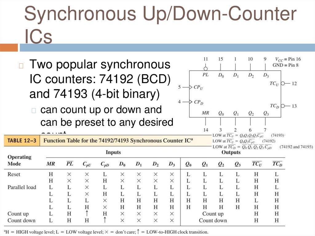
Synchronous Up/Down-CounterICs
◻
Two popular synchronous
IC counters: 74192 (BCD)
and 74193 (4-bit binary)
◻ can count up or down and
can be preset to any desired
count
42.
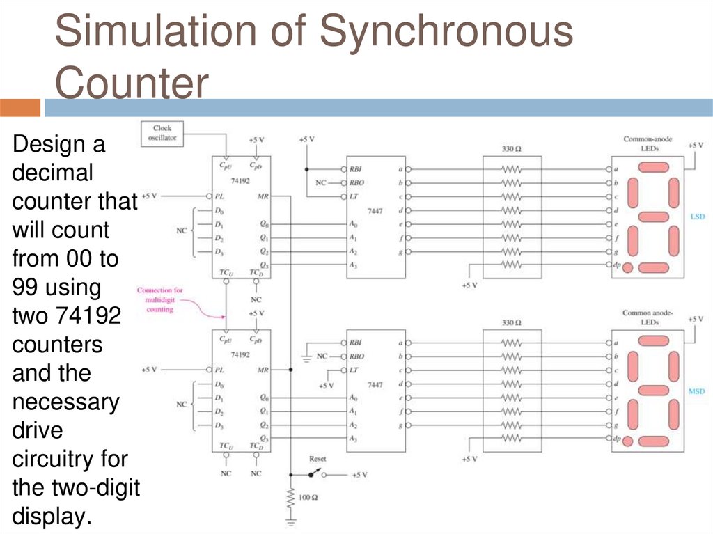
Simulation of SynchronousCounter
Design a
decimal
counter that
will count
from 00 to
99 using
two 74192
counters
and the
necessary
drive
circuitry for
the two-digit
display.
43.
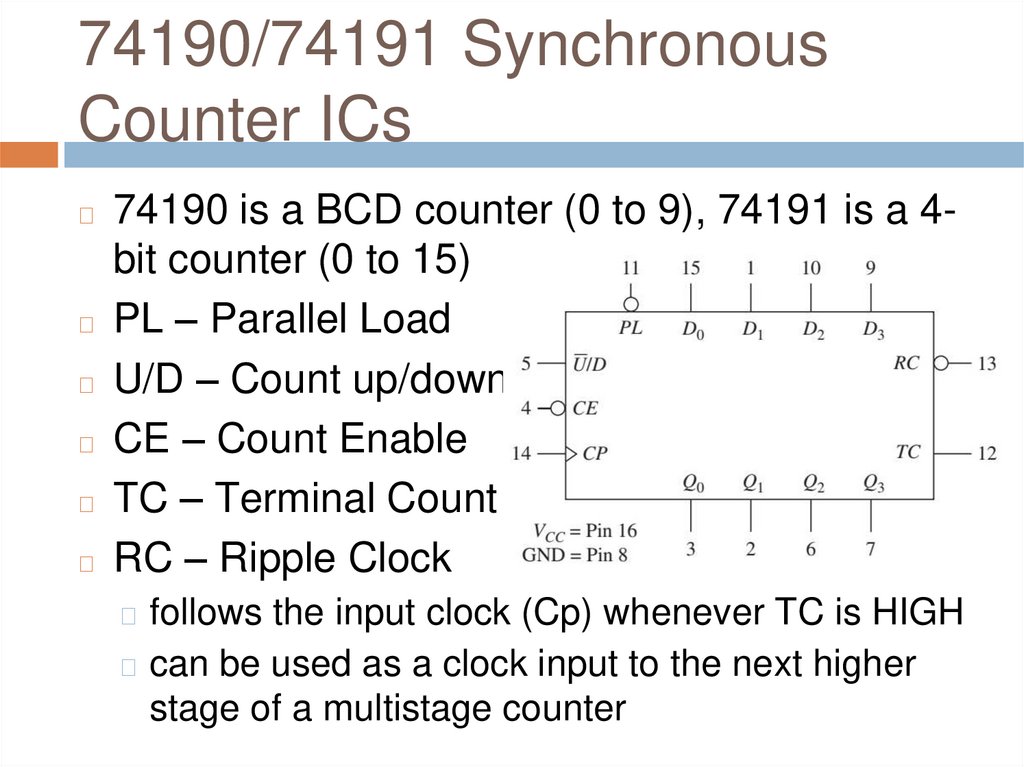
74190/74191 SynchronousCounter ICs
74190 is a BCD counter (0 to 9), 74191 is a 4bit counter (0 to 15)
◻ PL – Parallel Load
◻ U/D – Count up/down
◻ CE – Count Enable
◻ TC – Terminal Count
◻ RC – Ripple Clock
◻
◻ follows the input clock (Cp) whenever TC is HIGH
◻ can be used as a clock input to the next higher
stage of a multistage counter
44.
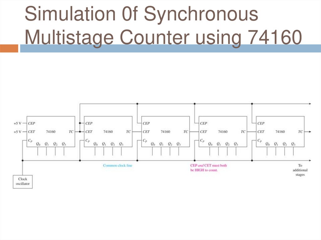
Synchronous MultistageCounter
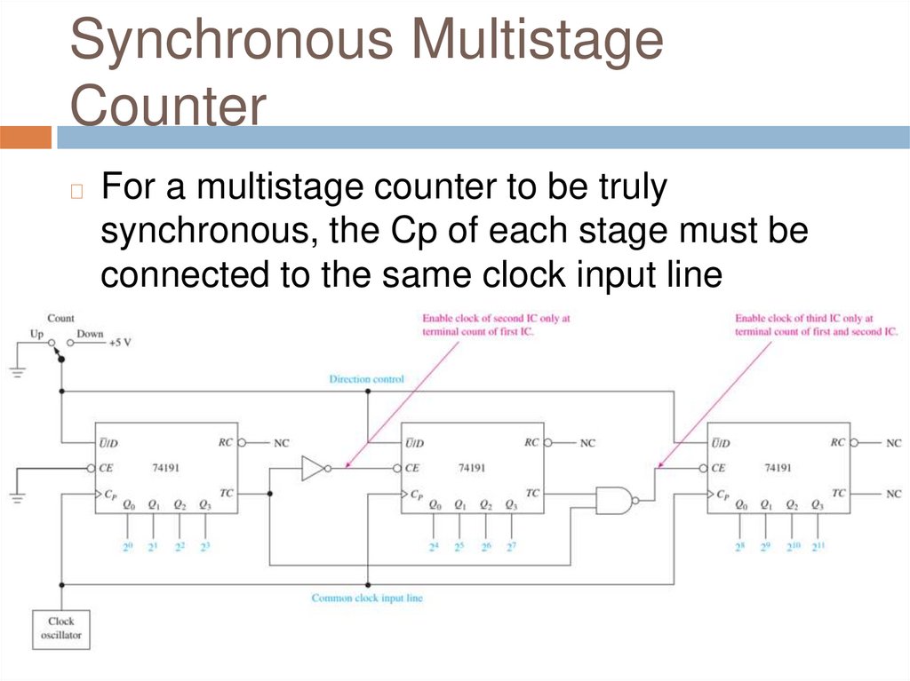
◻
For a multistage counter to be truly
synchronous, the Cp of each stage must be
connected to the same clock input line
45.
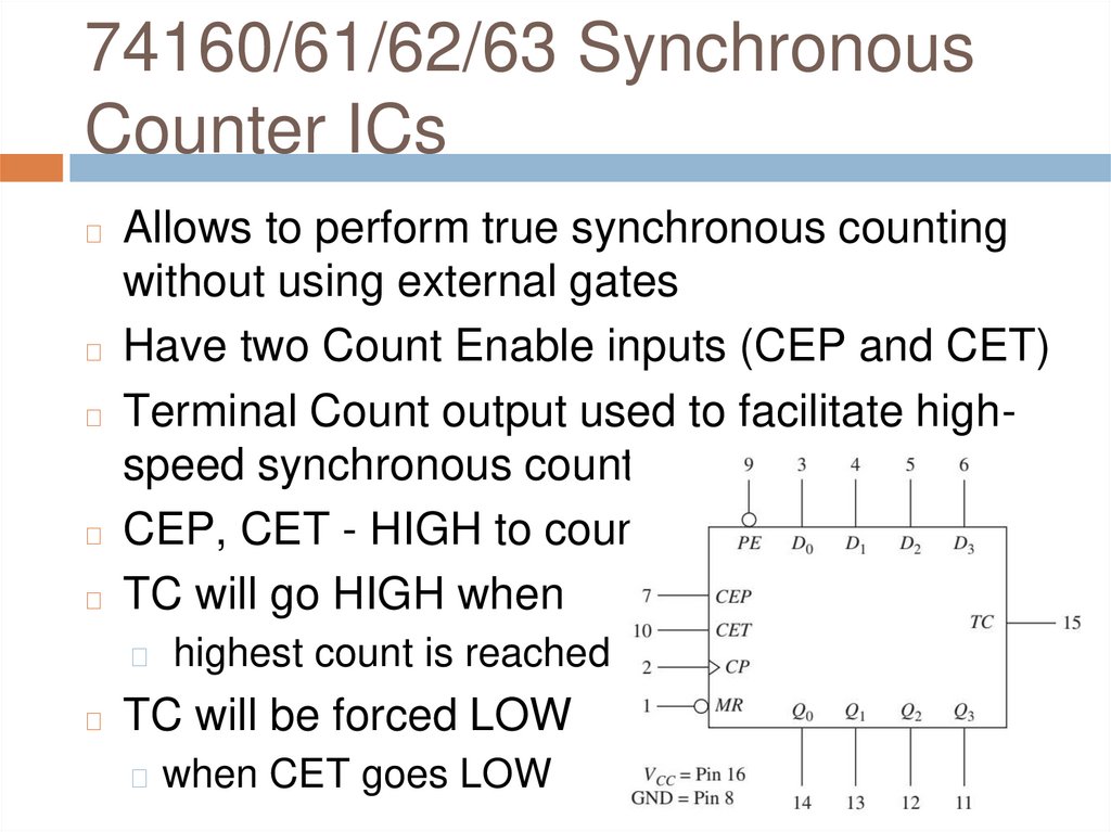
74160/61/62/63 SynchronousCounter ICs
Allows to perform true synchronous counting
without using external gates
◻ Have two Count Enable inputs (CEP and CET)
◻ Terminal Count output used to facilitate highspeed synchronous counting
◻ CEP, CET - HIGH to count
◻ TC will go HIGH when
◻
◻
◻
highest count is reached
TC will be forced LOW
◻ when CET goes LOW
46.
Simulation 0f SynchronousMultistage Counter using 74160
47.
Review Questions1.
2.
3.
What advantage do synchronous counters
have over ripple counters?
What is the function of the TCU and TCD
output pins on the 74193 synchronous
counter IC?
How do you change the 74190 from an upcounter to a down counter?
48.
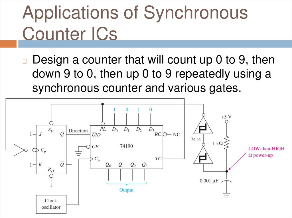
Applications of SynchronousCounter ICs
◻
Design a counter that will count up 0 to 9, then
down 9 to 0, then up 0 to 9 repeatedly using a
synchronous counter and various gates.
49.
Applications of SynchronousCounter ICs
◻
Design and sketch
the timing
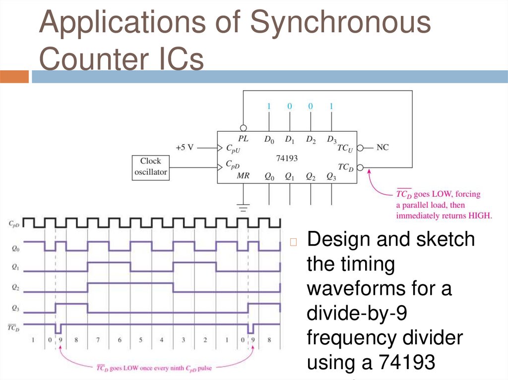
waveforms for a
divide-by-9
frequency divider
using a 74193
50.
Applications of SynchronousCounter ICs
◻
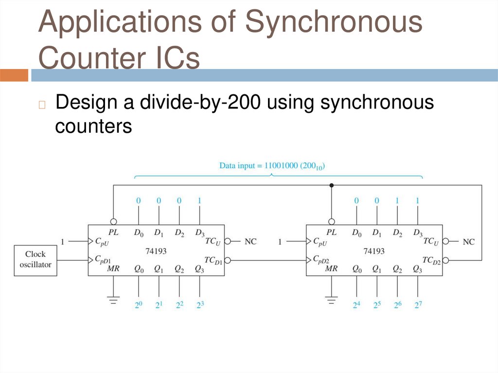
Design a divide-by-200 using synchronous
counters
51.
Applications of SynchronousCounter ICs
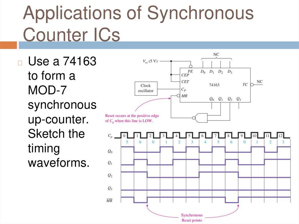
◻
Use a 74163
to form a
MOD-7
synchronous
up-counter.
Sketch the
timing
waveforms.
52.
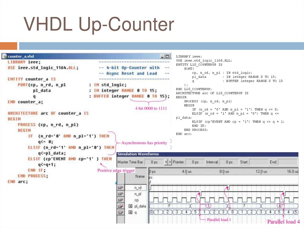
VHDL Up-CounterLIBRARY ieee;
USE ieee.std_logic_1164.ALL;
ENTITY L10_COUNTERUP IS
PORT(
cp, n_rd, n_pl : IN std_logic;
pl_data
: IN integer RANGE 0 TO 15;
q
: BUFFER integer RANGE 0 TO 15
);
END L10_COUNTERUP;
ARCHITECTURE arc OF L10_COUNTERUP IS
BEGIN
PROCESS (cp, n_rd, n_pl)
BEGIN
IF (n_rd = '0' AND n_pl = '1') THEN q <= 0;
ELSIF (n_rd = '1' AND n_pl = '0') THEN q <=
pl_data;
ELSIF (cp'EVENT AND cp = '1') THEN q <= q + 1;
END IF;
END PROCESS;
END arc;
53.
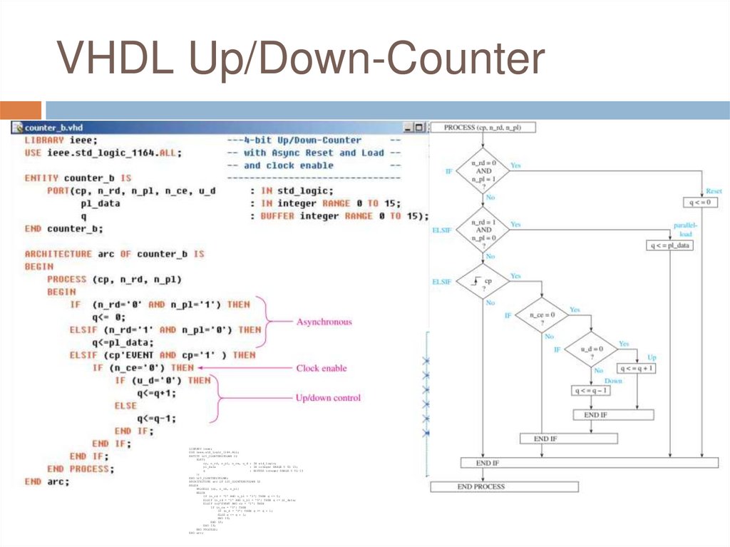
VHDL Up/Down-CounterLIBRARY ieee;
USE ieee.std_logic_1164.ALL;
ENTITY L10_COUNTERUPDOWN IS
PORT(
cp, n_rd, n_pl, n_ce, u_d : IN std_logic;
pl_data
: IN integer RANGE 0 TO 15;
q
: BUFFER integer RANGE 0 TO 15
);
END L10_COUNTERUPDOWN;
ARCHITECTURE arc OF L10_COUNTERUPDOWN IS
BEGIN
PROCESS (cp, n_rd, n_pl)
BEGIN
IF (n_rd = '0' AND n_pl = '1') THEN q <= 0;
ELSIF (n_rd = '1' AND n_pl = '0') THEN q <= pl_data;
ELSIF (cp'EVENT AND cp = '1') THEN
IF (n_ce = '0') THEN
IF (u_d = '0') THEN q <= q + 1;
ELSE q <= q - 1;
END IF;
END IF;
END IF;
END PROCESS;
END arc;
54.
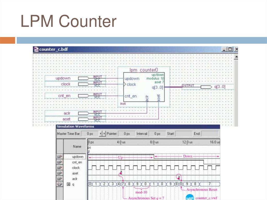
LPM Counter55.
Implementing State Machines inVHDL
Many processes in digital electronics follow a
predefined sequence of steps initiated by a
series of clock pulses
◻ These processes can be driven by a single
clock input so that outputs respond in a
particular order
◻ This sequence of events can be implemented
in a logic system called a state machine
◻ The outputs of a state machine follow a
predictable sequence, triggered by a clock and
other input stimulus
◻
56.
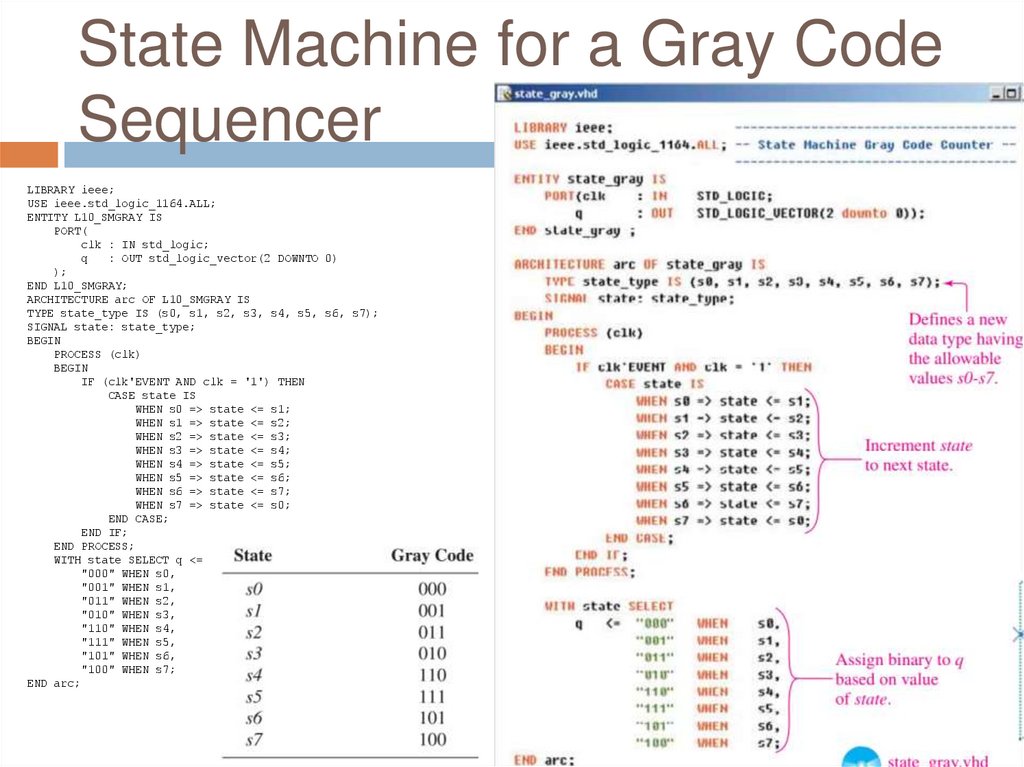
State Machine for a Gray CodeSequencer
LIBRARY ieee;
USE ieee.std_logic_1164.ALL;
ENTITY L10_SMGRAY IS
PORT(
clk : IN std_logic;
q
: OUT std_logic_vector(2 DOWNTO 0)
);
END L10_SMGRAY;
ARCHITECTURE arc OF L10_SMGRAY IS
TYPE state_type IS (s0, s1, s2, s3, s4, s5, s6, s7);
SIGNAL state: state_type;
BEGIN
PROCESS (clk)
BEGIN
IF (clk'EVENT AND clk = '1') THEN
CASE state IS
WHEN s0 => state <= s1;
WHEN s1 => state <= s2;
WHEN s2 => state <= s3;
WHEN s3 => state <= s4;
WHEN s4 => state <= s5;
WHEN s5 => state <= s6;
WHEN s6 => state <= s7;
WHEN s7 => state <= s0;
END CASE;
END IF;
END PROCESS;
WITH state SELECT q <=
"000" WHEN s0,
"001" WHEN s1,
"011" WHEN s2,
"010" WHEN s3,
"110" WHEN s4,
"111" WHEN s5,
"101" WHEN s6,
"100" WHEN s7;
END arc;
57.
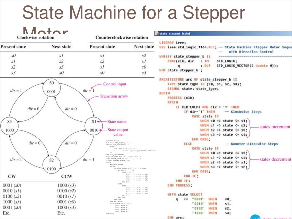
State Machine for a StepperMotor
LIBRARY ieee;
USE ieee.std_logic_1164.ALL;
ENTITY L10_SMSTEPPER IS
PORT(
clk, dir : IN std_logic;
q
: OUT std_logic_vector(3 DOWNTO 0)
);
END L10_SMSTEPPER;
ARCHITECTURE arc OF L10_SMSTEPPER IS
TYPE state_type IS (s0, s1, s2, s3);
SIGNAL state: state_type;
BEGIN
PROCESS (clk)
BEGIN
IF (clk'EVENT AND clk = '1') THEN
IF dir = '1' THEN
CASE state IS
WHEN s0 => state <= s1;
WHEN s1 => state <= s2;
WHEN s2 => state <= s3;
WHEN s3 => state <= s0;
END CASE;
ELSE
CASE state IS
WHEN s0 => state <= s3;
WHEN s1 => state <= s0;
WHEN s2 => state <= s1;
WHEN s3 => state <= s2;
END CASE;
END IF;
END IF;
END PROCESS;
WITH state SELECT q <=
"0001" WHEN s0,
"0010" WHEN s1,
"0100" WHEN s2,
"1000" WHEN s3;
END arc;
58.
Q&AAny Questions?