


 electronics
Similar presentations:


")


Arithmetic Operations and Circuits. Digital Electronics (lecture 6)
1.
Arithmetic Operations and CircuitsLecture 6
Digital Electronics
2.
Course MaterialsAll needed Software and course materials will
be located on Canvas.
◻ Materials that are used in this slides are taken
from the textbook “Digital Electronics A
Practical Approach with VHDL” by William
Kleitz
◻
3.
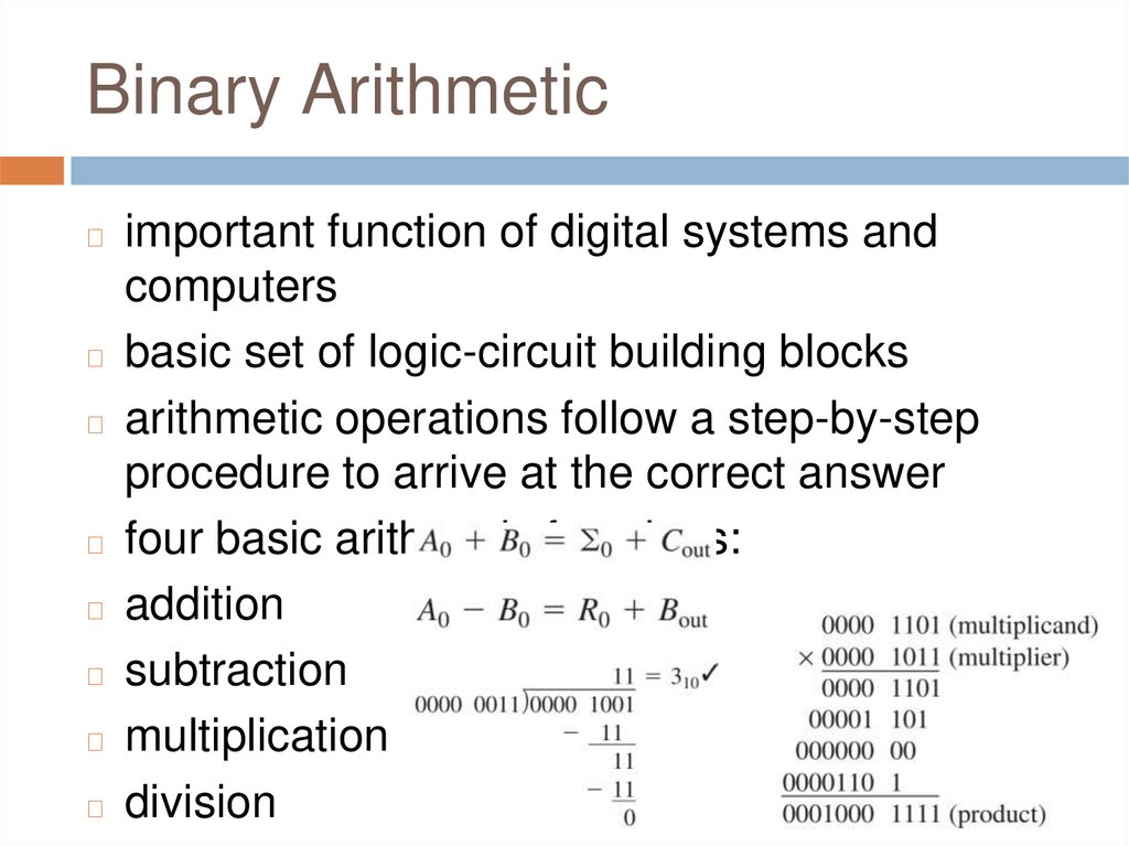
Binary Arithmeticimportant function of digital systems and
computers
◻ basic set of logic-circuit building blocks
◻ arithmetic operations follow a step-by-step
procedure to arrive at the correct answer
◻ four basic arithmetic functions:
◻ addition
◻ subtraction
◻ multiplication
◻ division
◻
4.
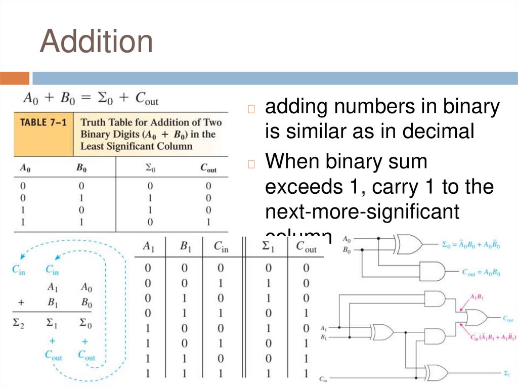
Additionadding numbers in binary
is similar as in decimal
◻ When binary sum
exceeds 1, carry 1 to the
next-more-significant
column
◻
5.
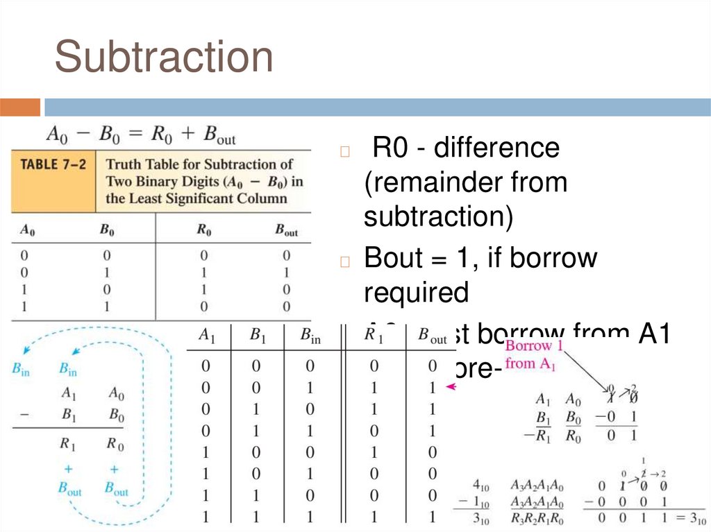
SubtractionR0 - difference
(remainder from
subtraction)
◻ Bout = 1, if borrow
required
◻ A0 must borrow from A1
next-more-significant
column
◻
6.
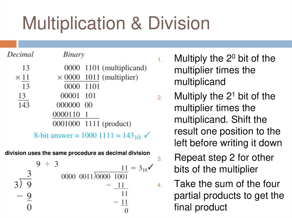
Multiplication & Division1.
2.
division uses the same procedure as decimal division
3.
4.
Multiply the 20 bit of the
multiplier times the
multiplicand
Multiply the 21 bit of the
multiplier times the
multiplicand. Shift the
result one position to the
left before writing it down
Repeat step 2 for other
bits of the multiplier
Take the sum of the four
partial products to get the
final product
7.
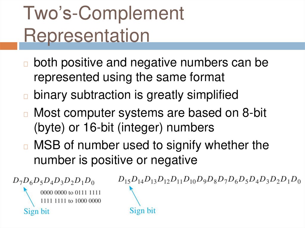
Two’s-ComplementRepresentation
both positive and negative numbers can be
represented using the same format
◻ binary subtraction is greatly simplified
◻ Most computer systems are based on 8-bit
(byte) or 16-bit (integer) numbers
◻ MSB of number used to signify whether the
number is positive or negative
◻
8.
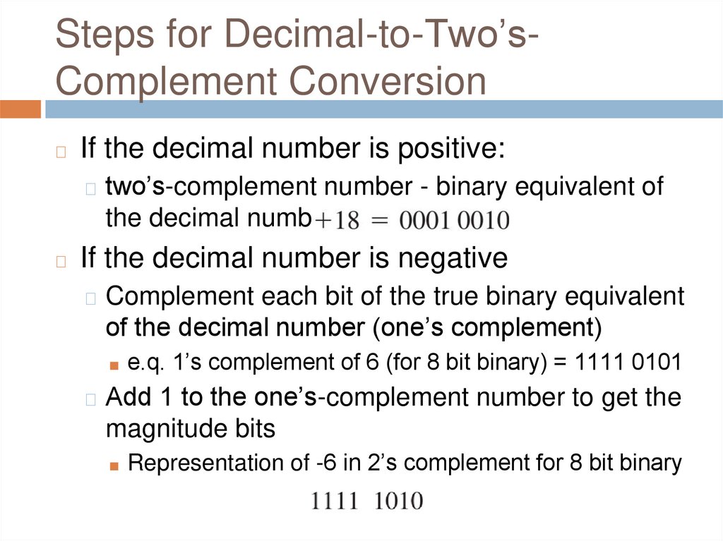
Steps for Decimal-to-Two’sComplement Conversion◻
If the decimal number is positive:
◻ two’s-complement number - binary equivalent of
the decimal number
◻
If the decimal number is negative
◻ Complement each bit of the true binary equivalent
of the decimal number (one’s complement)
■ e.q. 1’s complement of 6 (for 8 bit binary) = 1111 0101
◻ Add 1 to the one’s-complement number to get the
magnitude bits
■ Representation of -6 in 2’s complement for 8 bit binary
9.
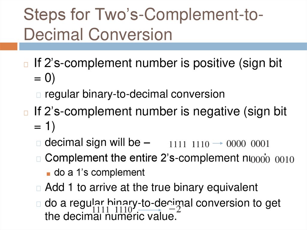
Steps for Two’s-Complement-toDecimal Conversion◻
If 2’s-complement number is positive (sign bit
= 0)
◻ regular binary-to-decimal conversion
◻
If 2’s-complement number is negative (sign bit
= 1)
◻ decimal sign will be –
◻ Complement the entire 2’s-complement number
■ do a 1’s complement
◻ Add 1 to arrive at the true binary equivalent
◻ do a regular binary-to-decimal conversion to get
the decimal numeric value.
10.
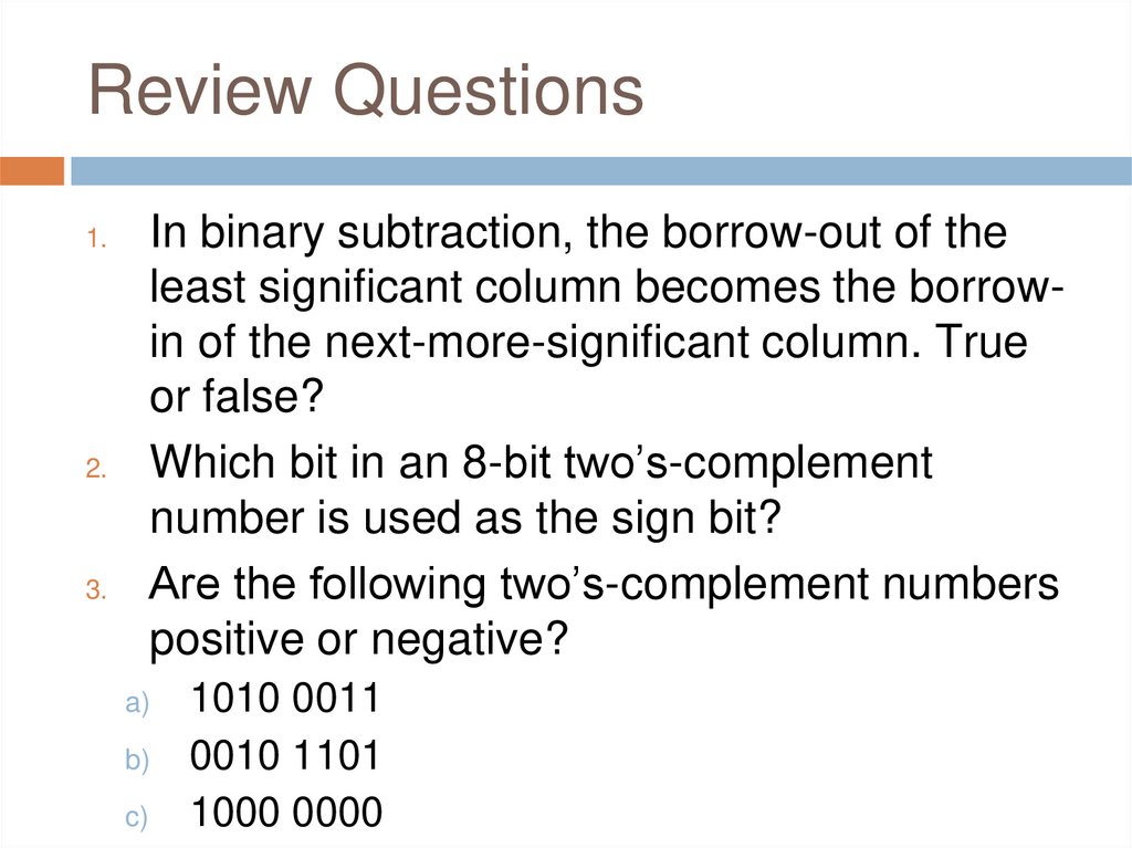
Review QuestionsIn binary subtraction, the borrow-out of the
least significant column becomes the borrowin of the next-more-significant column. True
or false?
Which bit in an 8-bit two’s-complement
number is used as the sign bit?
Are the following two’s-complement numbers
positive or negative?
1.
2.
3.
a)
b)
c)
1010 0011
0010 1101
1000 0000
11.
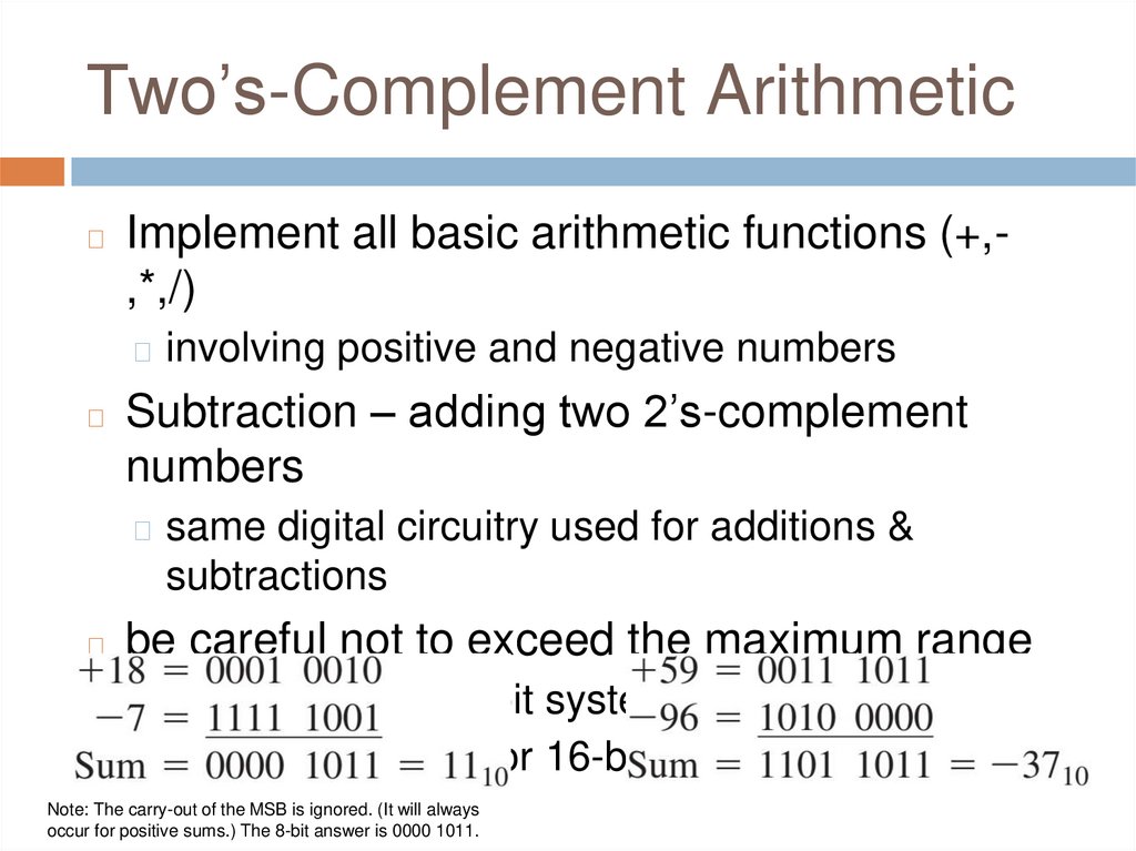
Two’s-Complement Arithmetic◻
Implement all basic arithmetic functions (+,,*,/)
◻ involving positive and negative numbers
◻
Subtraction – adding two 2’s-complement
numbers
◻ same digital circuitry used for additions &
subtractions
◻
be careful not to exceed the maximum range
◻ +127…-128 for 8-bit systems
◻ +32767…-32768 for 16-bit systems
Note: The carry-out of the MSB is ignored. (It will always
occur for positive sums.) The 8-bit answer is 0000 1011.
12.
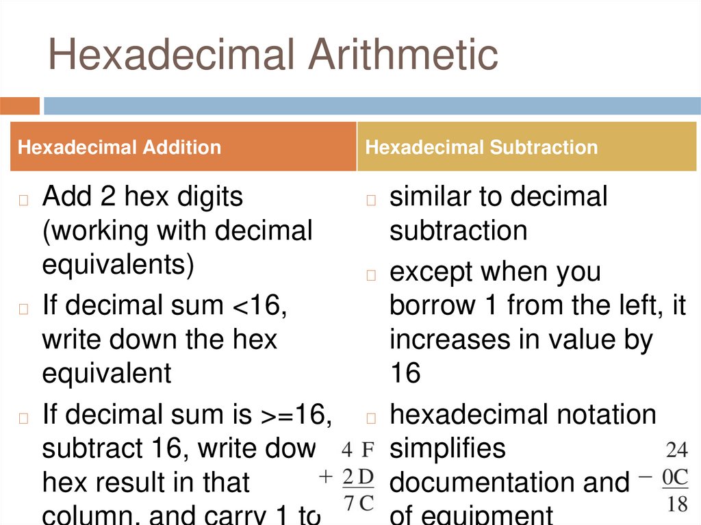
Hexadecimal ArithmeticHexadecimal Addition
Hexadecimal Subtraction
Add 2 hex digits
(working with decimal
equivalents)
◻ If decimal sum <16,
write down the hex
equivalent
◻ If decimal sum is >=16,
subtract 16, write down
hex result in that
column, and carry 1 to
◻
◻
similar to decimal
subtraction
◻ except when you
borrow 1 from the left, it
increases in value by
16
◻ hexadecimal notation
simplifies
documentation and use
of equipment
13.
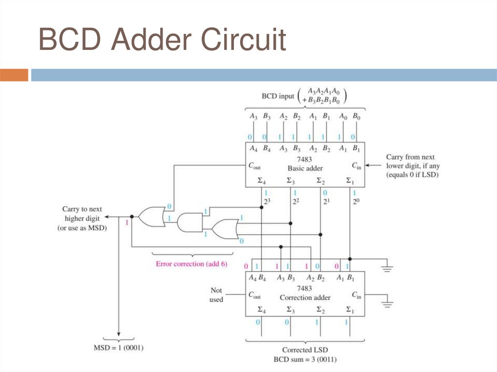
BCD ArithmeticRepeat steps below for each group of BCD bits
◻ Add BCD numbers as regular true binary numbers
◻ if the sum is <= 9 (1001)
◻
◻
◻
it is a valid BCD answer; leave it as is
If the sum is > 9 or there is a carry-out of the MSB
it is an invalid BCD number
◻ add 6 (0110) to the result to make it valid
◻ any carry-out of the MSB is added to the next-more-significant
BCD number.
◻
14.
Review Questions1.
2.
3.
4.
Which of the following decimal numbers
cannot be converted to 8-bit two’scomplement notation?
(a) 89 (b) 135
(c) -107
(d) -144
The procedure for subtracting numbers in
two’s-complement notation is exactly the
same as for adding numbers. True or false?
When subtracting hex digits, if the least
significant digit borrows from its left, its value
increases by ___________?
What procedure is used to correct the result
15.
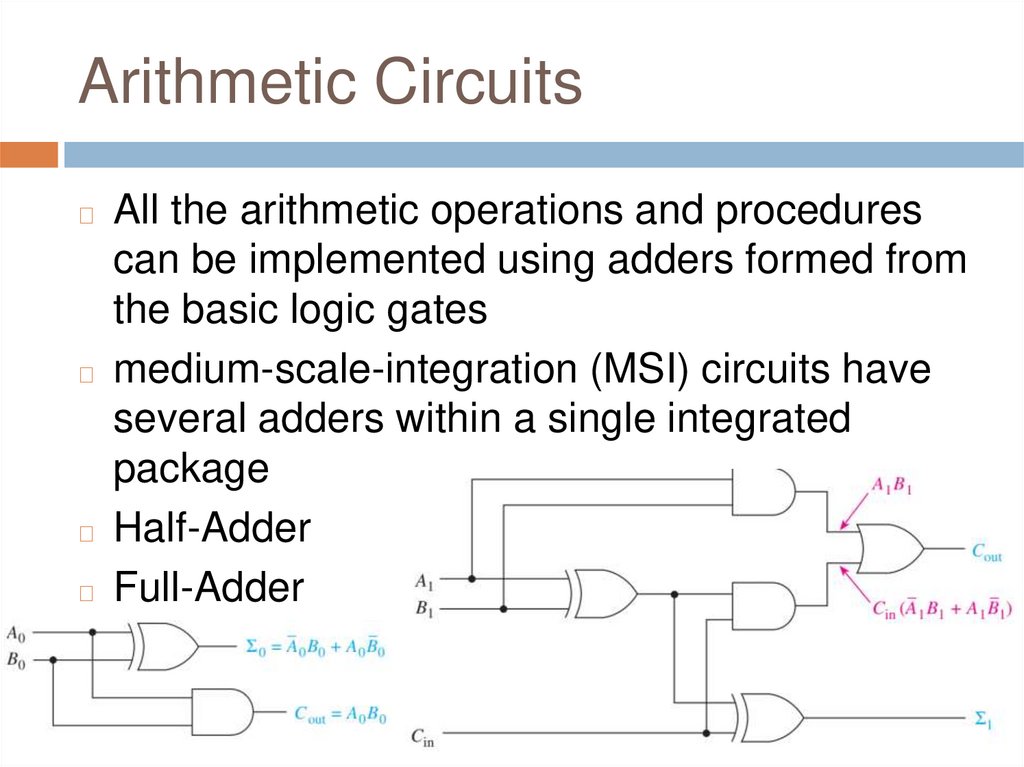
Arithmetic CircuitsAll the arithmetic operations and procedures
can be implemented using adders formed from
the basic logic gates
◻ medium-scale-integration (MSI) circuits have
several adders within a single integrated
package
◻ Half-Adder
◻ Full-Adder
◻
16.
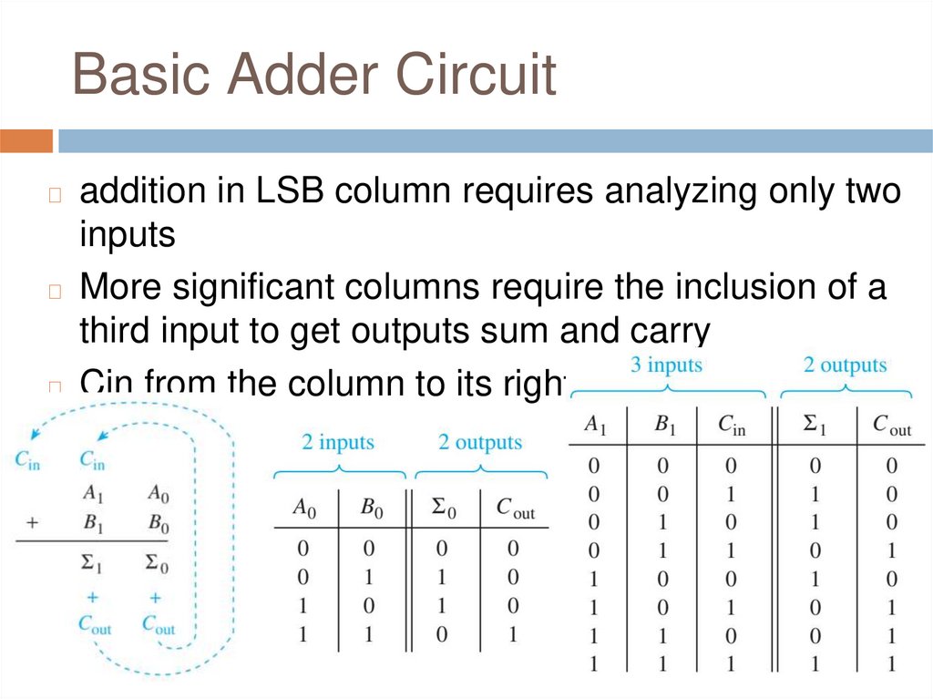
Basic Adder Circuitaddition in LSB column requires analyzing only two
inputs
◻ More significant columns require the inclusion of a
third input to get outputs sum and carry
◻ Cin from the column to its right
◻
17.
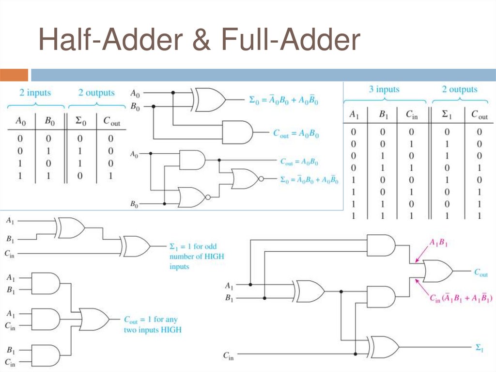
Half-Adder & Full-Adder18.
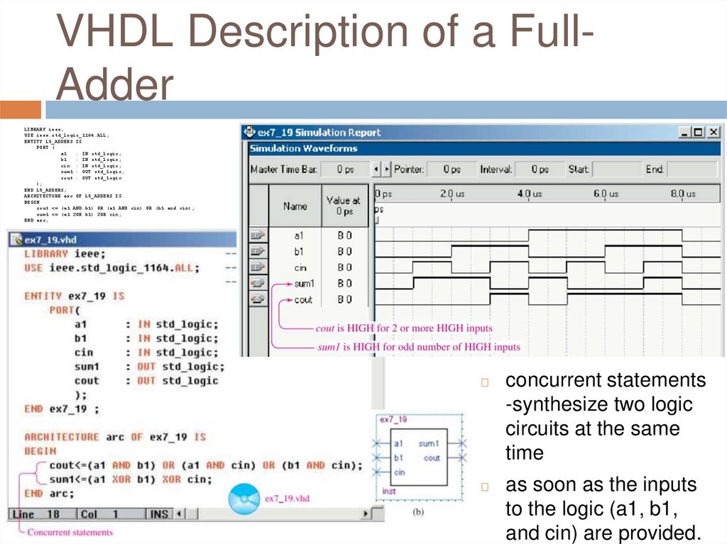
VHDL Description of a FullAdderLIBRARY ieee;
USE ieee.std_logic_1164.ALL;
ENTITY L5_ADDERS IS
PORT (
a1
: IN std_logic;
b1
: IN std_logic;
cin : IN std_logic;
sum1 : OUT std_logic;
cout : OUT std_logic
);
END L5_ADDERS;
ARCHITECTURE arc OF L5_ADDERS IS
BEGIN
cout <= (a1 AND b1) OR (a1 AND cin) OR (b1 and cin);
sum1 <= (a1 XOR b1) XOR cin;
END arc;
◻
concurrent statements
-synthesize two logic
circuits at the same
time
◻
as soon as the inputs
to the logic (a1, b1,
and cin) are provided.
19.
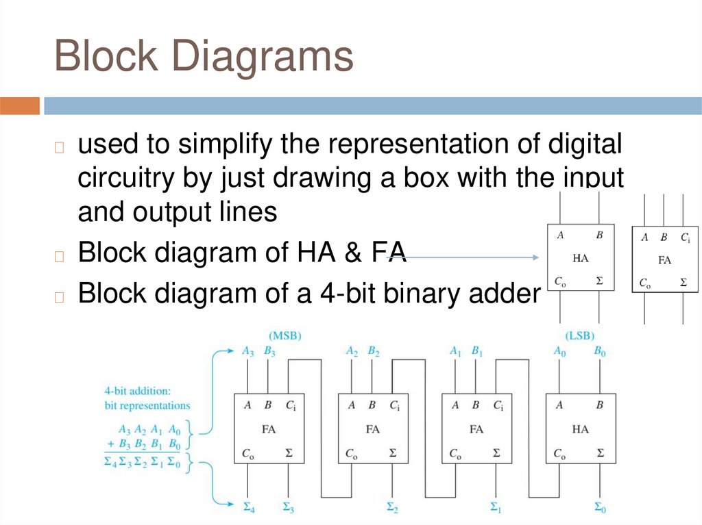
Block Diagramsused to simplify the representation of digital
circuitry by just drawing a box with the input
and output lines
◻ Block diagram of HA & FA
◻ Block diagram of a 4-bit binary adder
◻
20.
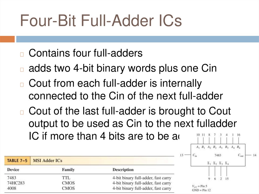
Four-Bit Full-Adder ICsContains four full-adders
◻ adds two 4-bit binary words plus one Cin
◻ Cout from each full-adder is internally
connected to the Cin of the next full-adder
◻ Cout of the last full-adder is brought to Cout
output to be used as Cin to the next fulladder
IC if more than 4 bits are to be added
◻
21.
22.
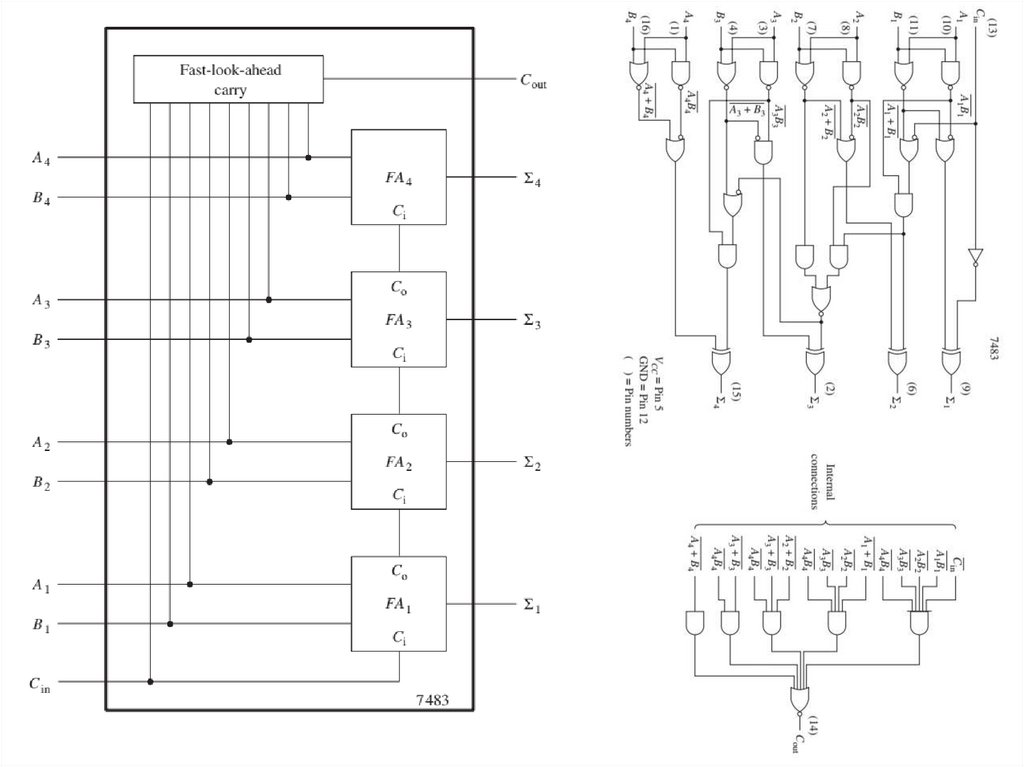
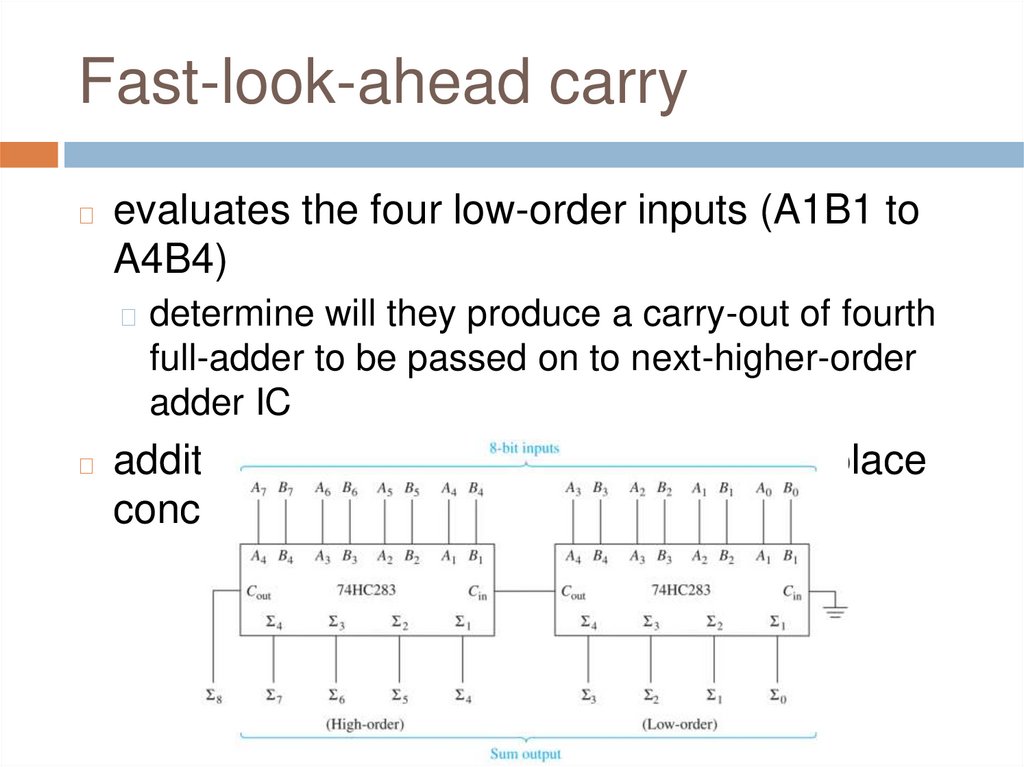
Fast-look-ahead carry◻
evaluates the four low-order inputs (A1B1 to
A4B4)
◻ determine will they produce a carry-out of fourth
full-adder to be passed on to next-higher-order
adder IC
◻
addition of the high-order bits can take place
concurrently with the low-order addition
23.
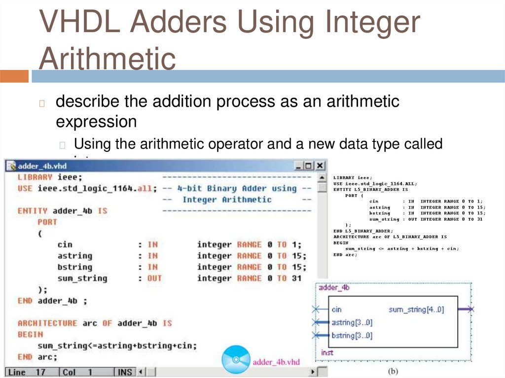
VHDL Adders Using IntegerArithmetic
◻
describe the addition process as an arithmetic
expression
◻ Using the arithmetic operator and a new data type called
integer
◻ When declaring specify the range of the integer value
LIBRARY ieee;
USE ieee.std_logic_1164.ALL;
ENTITY L5_BINARY_ADDER IS
PORT (
cin
: IN INTEGER RANGE 0 TO 1;
astring
: IN INTEGER RANGE 0 TO 15;
bstring
: IN INTEGER RANGE 0 TO 15;
sum_string : OUT INTEGER RANGE 0 TO 31
);
END L5_BINARY_ADDER;
ARCHITECTURE arc OF L5_BINARY_ADDER IS
BEGIN
sum_string <= astring + bstring + cin;
END arc;
24.
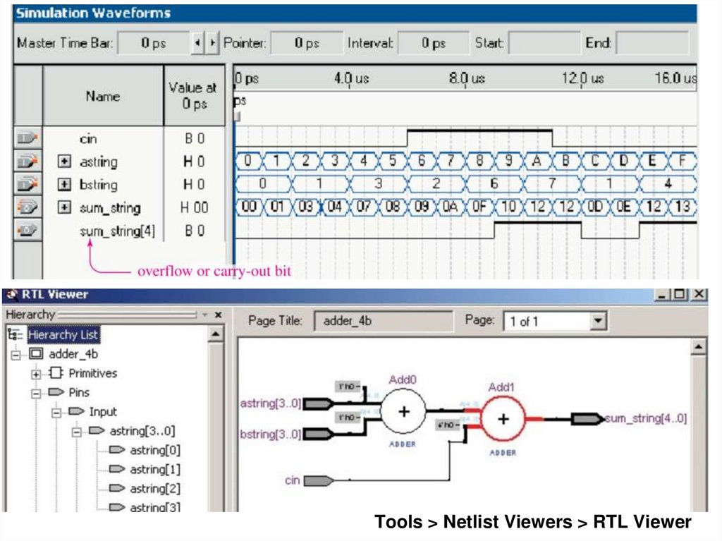
Tools > Netlist Viewers > RTL Viewer25.
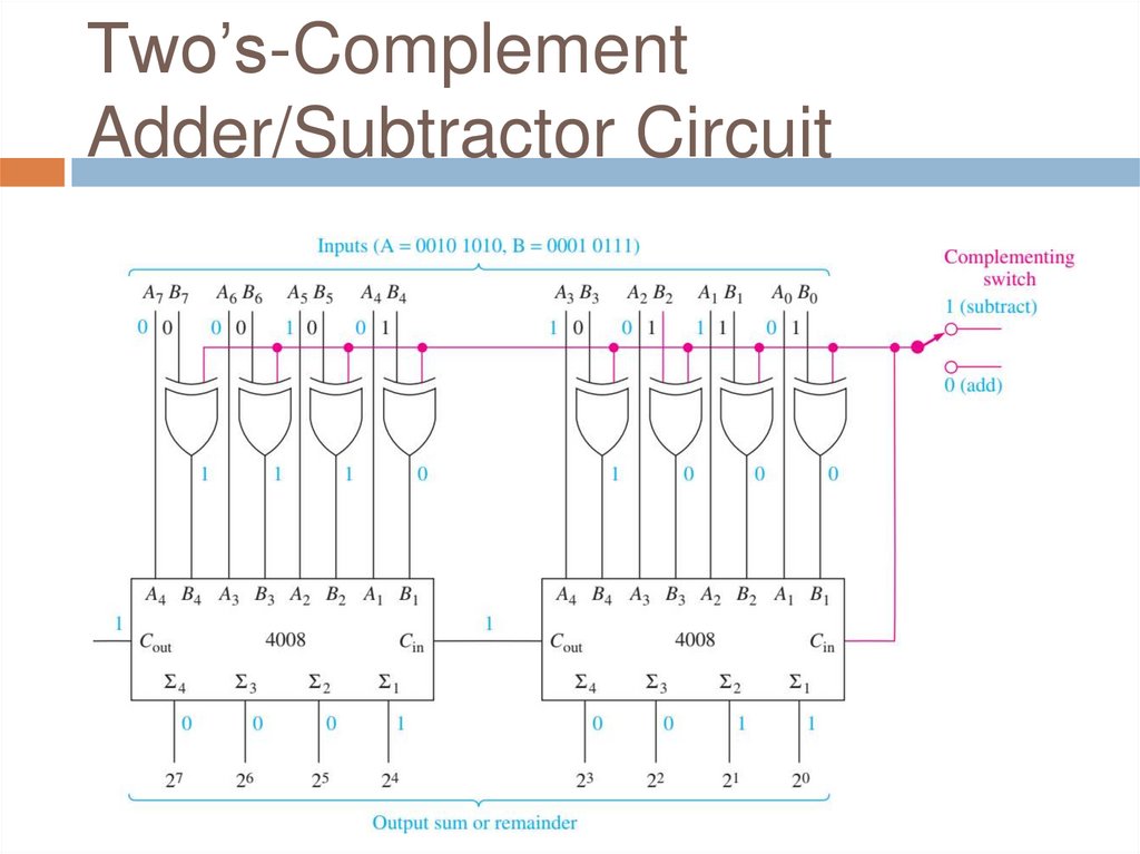
Two’s-ComplementAdder/Subtractor Circuit
26.
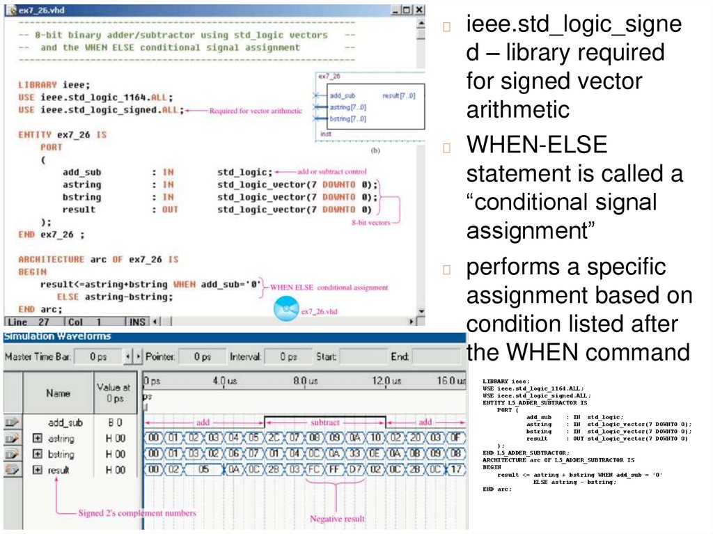
ieee.std_logic_signed – library required
for signed vector
arithmetic
◻ WHEN-ELSE
statement is called a
“conditional signal
assignment”
◻ performs a specific
assignment based on
condition listed after
the WHEN command
◻
LIBRARY ieee;
USE ieee.std_logic_1164.ALL;
USE ieee.std_logic_signed.ALL;
ENTITY L5_ADDER_SUBTRACTOR IS
PORT (
add_sub
: IN std_logic;
astring
: IN std_logic_vector(7 DOWNTO 0);
bstring
: IN std_logic_vector(7 DOWNTO 0);
result
: OUT std_logic_vector(7 DOWNTO 0)
);
END L5_ADDER_SUBTRACTOR;
ARCHITECTURE arc OF L5_ADDER_SUBTRACTOR IS
BEGIN
result <= astring + bstring WHEN add_sub = '0'
ELSE astring - bstring;
END arc;
27.
BCD Adder Circuit28.
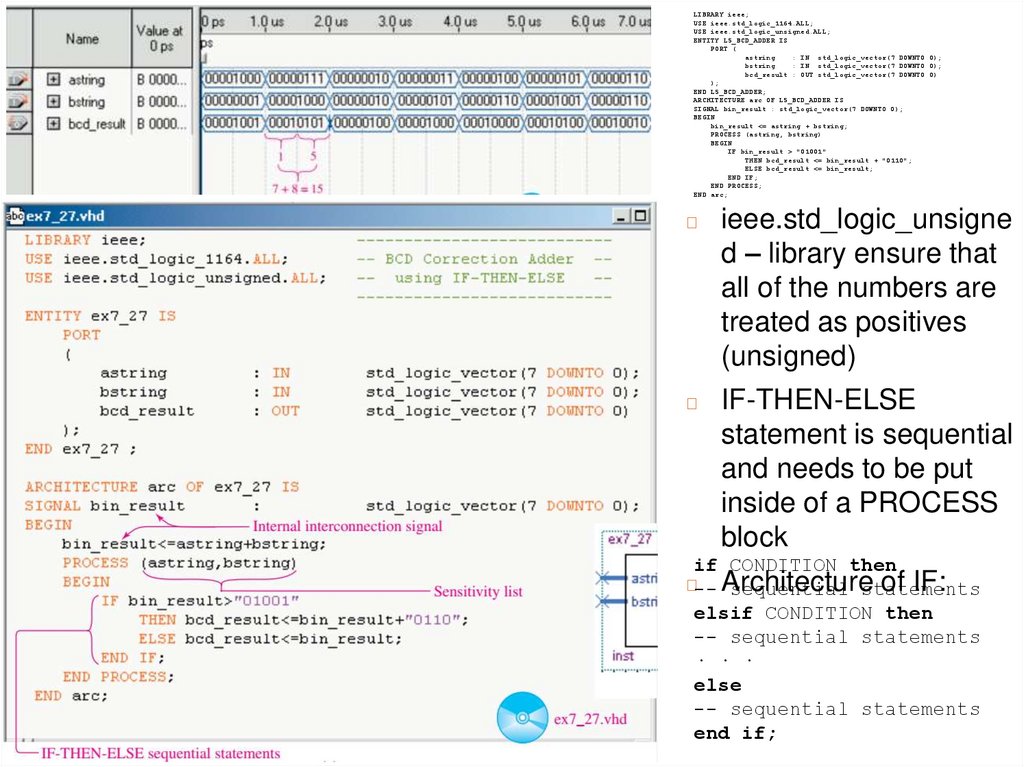
LIBRARY ieee;USE ieee.std_logic_1164.ALL;
USE ieee.std_logic_unsigned.ALL;
ENTITY L5_BCD_ADDER IS
PORT (
astring
: IN std_logic_vector(7 DOWNTO 0);
bstring
: IN std_logic_vector(7 DOWNTO 0);
bcd_result : OUT std_logic_vector(7 DOWNTO 0)
);
END L5_BCD_ADDER;
ARCHITECTURE arc OF L5_BCD_ADDER IS
SIGNAL bin_result : std_logic_vector(7 DOWNTO 0);
BEGIN
bin_result <= astring + bstring;
PROCESS (astring, bstring)
BEGIN
IF bin_result > "01001"
THEN bcd_result <= bin_result + "0110";
ELSE bcd_result <= bin_result;
END IF;
END PROCESS;
END arc;
◻
ieee.std_logic_unsigne
d – library ensure that
all of the numbers are
treated as positives
(unsigned)
◻
IF-THEN-ELSE
statement is sequential
and needs to be put
inside of a PROCESS
block
if CONDITION then
Architecture of IF:
◻-- sequential statements
elsif CONDITION then
-- sequential statements
· · ·
else
-- sequential statements
end if;
29.
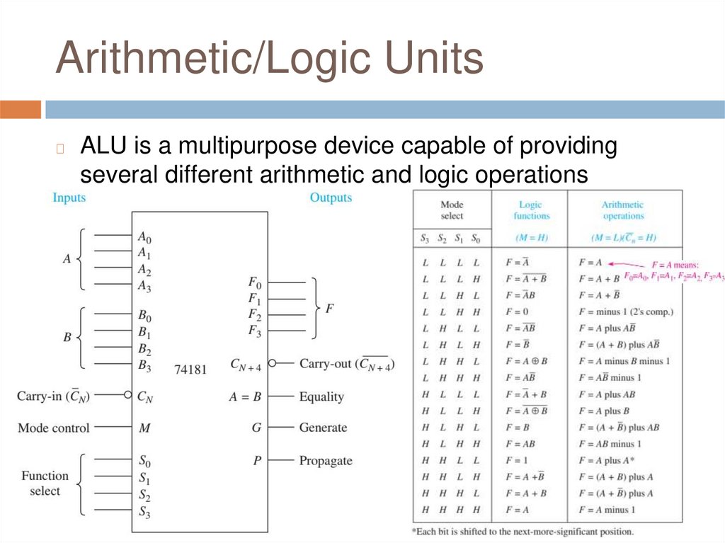
Arithmetic/Logic Units◻
ALU is a multipurpose device capable of providing
several different arithmetic and logic operations
30.
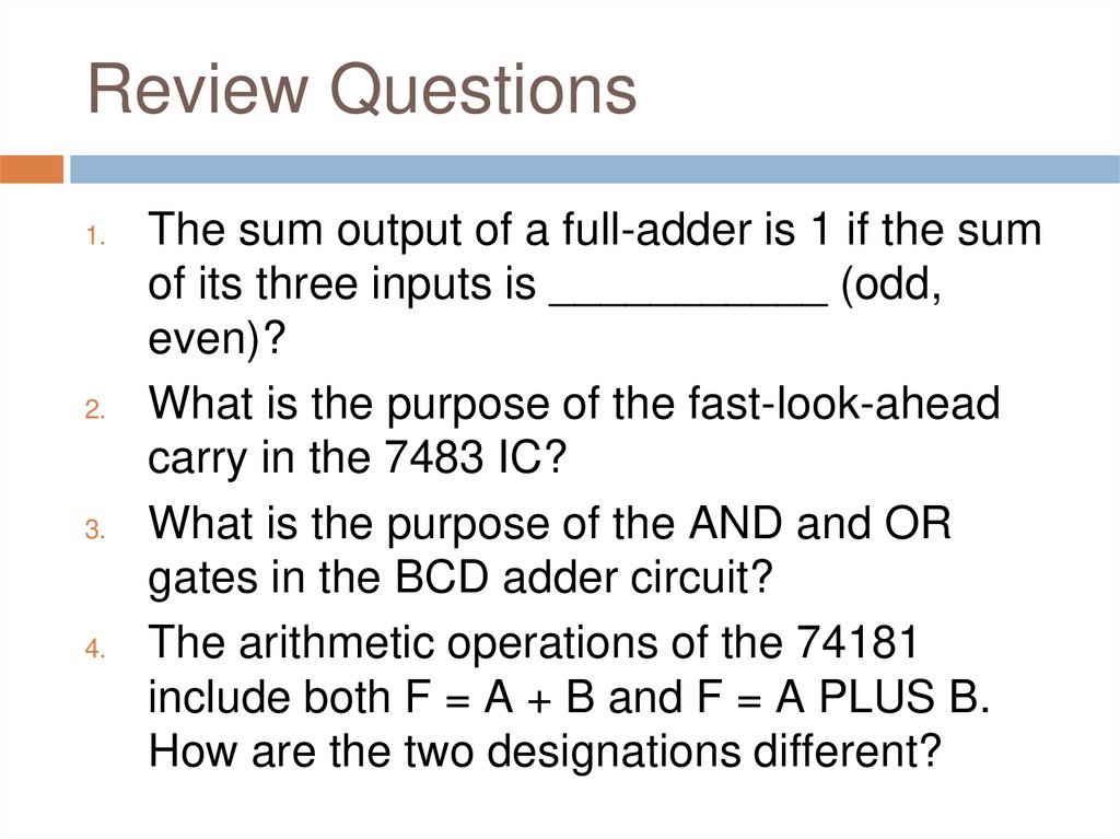
Review Questions1.
2.
3.
4.
The sum output of a full-adder is 1 if the sum
of its three inputs is ___________ (odd,
even)?
What is the purpose of the fast-look-ahead
carry in the 7483 IC?
What is the purpose of the AND and OR
gates in the BCD adder circuit?
The arithmetic operations of the 74181
include both F = A + B and F = A PLUS B.
How are the two designations different?
31.
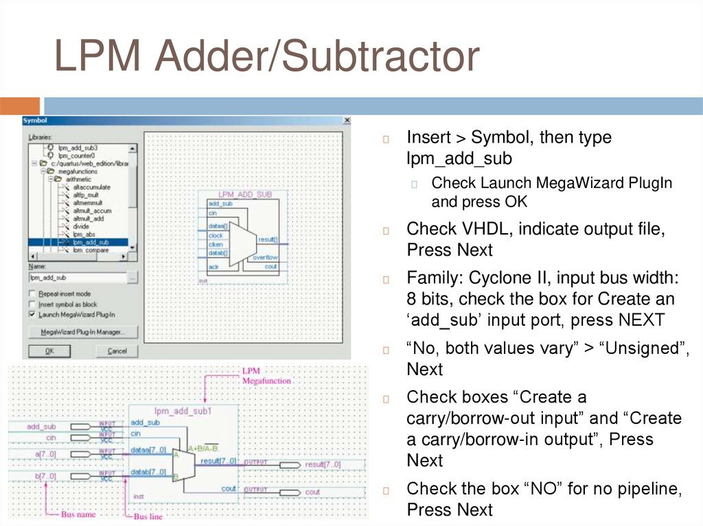
LPM Adder/Subtractor◻
Insert > Symbol, then type
lpm_add_sub
◻
Check Launch MegaWizard PlugIn
and press OK
◻
Check VHDL, indicate output file,
Press Next
◻
Family: Cyclone II, input bus width:
8 bits, check the box for Create an
‘add_sub’ input port, press NEXT
◻
◻
◻
“No, both values vary” > “Unsigned”,
Next
Check boxes “Create a
carry/borrow-out input” and “Create
a carry/borrow-in output”, Press
Next
Check the box “NO” for no pipeline,
Press Next
32.
33.
34.
35.
a) 21 - 13b) 54 118
36.
37.
Q&AAny Questions?