

 electronics
Similar presentations:

")


Exclusive -OR and Exclusive -NOR. Gates. Digital Electronics (lecture 5)
1.
Exclusive-OR and Exclusive-NORGates
Lecture 5
Digital Electronics
2.
Course MaterialsAll needed Software and course materials will
be located on Canvas.
◻ Materials that are used in this slides are taken
from the textbook “Digital Electronics A
Practical Approach with VHDL” by William
Kleitz
◻
3.
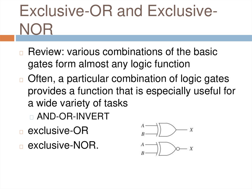
Exclusive-OR and ExclusiveNORReview: various combinations of the basic
gates form almost any logic function
◻ Often, a particular combination of logic gates
provides a function that is especially useful for
a wide variety of tasks
◻
◻ AND-OR-INVERT
exclusive-OR
◻ exclusive-NOR.
◻
4.
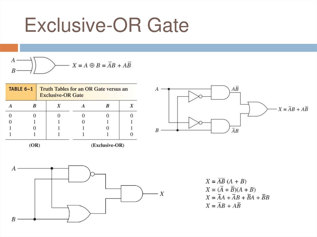
Exclusive-OR Gate5.
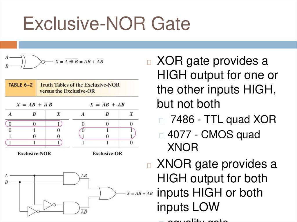
Exclusive-NOR Gate◻
XOR gate provides a
HIGH output for one or
the other inputs HIGH,
but not both
7486 - TTL quad XOR
◻ 4077 - CMOS quad
XNOR
◻
◻
XNOR gate provides a
HIGH output for both
inputs HIGH or both
inputs LOW
6.
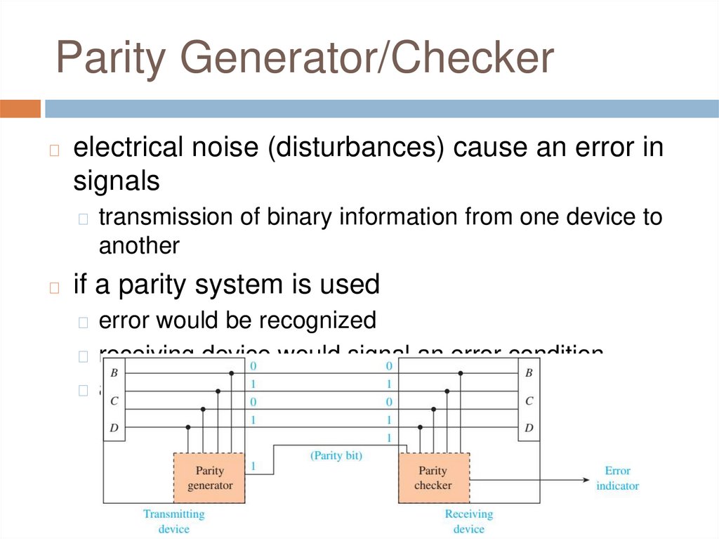
Parity Generator/Checker◻
electrical noise (disturbances) cause an error in
signals
◻ transmission of binary information from one device to
another
◻
if a parity system is used
◻ error would be recognized
◻ receiving device would signal an error condition
◻ ask the transmitting device to retransmit
7.
Parity◻
odd parity or even parity
◻ extra bit to the digital information being
transmitted
◻ depending on what the other bits are
◻ type must be agreed on beforehand (protocol)
◻ parity bit can be placed next to the MSB or LSB
odd-parity bit - makes the sum of all bits odd
◻ even-parity bit - makes the sum of all bits even
◻ parity generator - circuit that creates the parity
bit
◻ parity checker - determines if the result is of
◻
8.
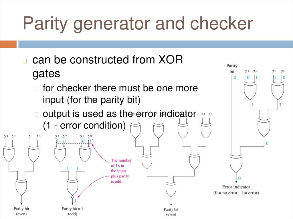
Parity generator and checker◻
can be constructed from XOR
gates
◻ for checker there must be one more
input (for the parity bit)
◻ output is used as the error indicator
(1 - error condition)
9.
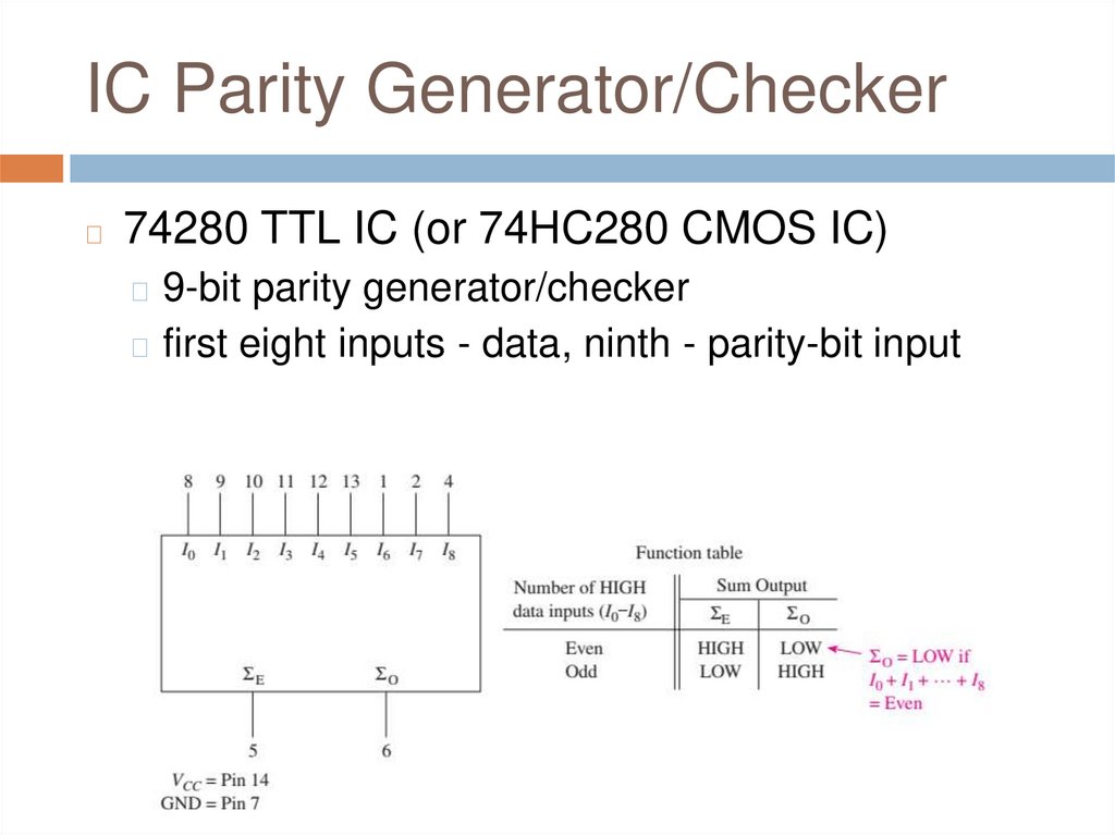
IC Parity Generator/Checker◻
74280 TTL IC (or 74HC280 CMOS IC)
◻ 9-bit parity generator/checker
◻ first eight inputs - data, ninth - parity-bit input
10.
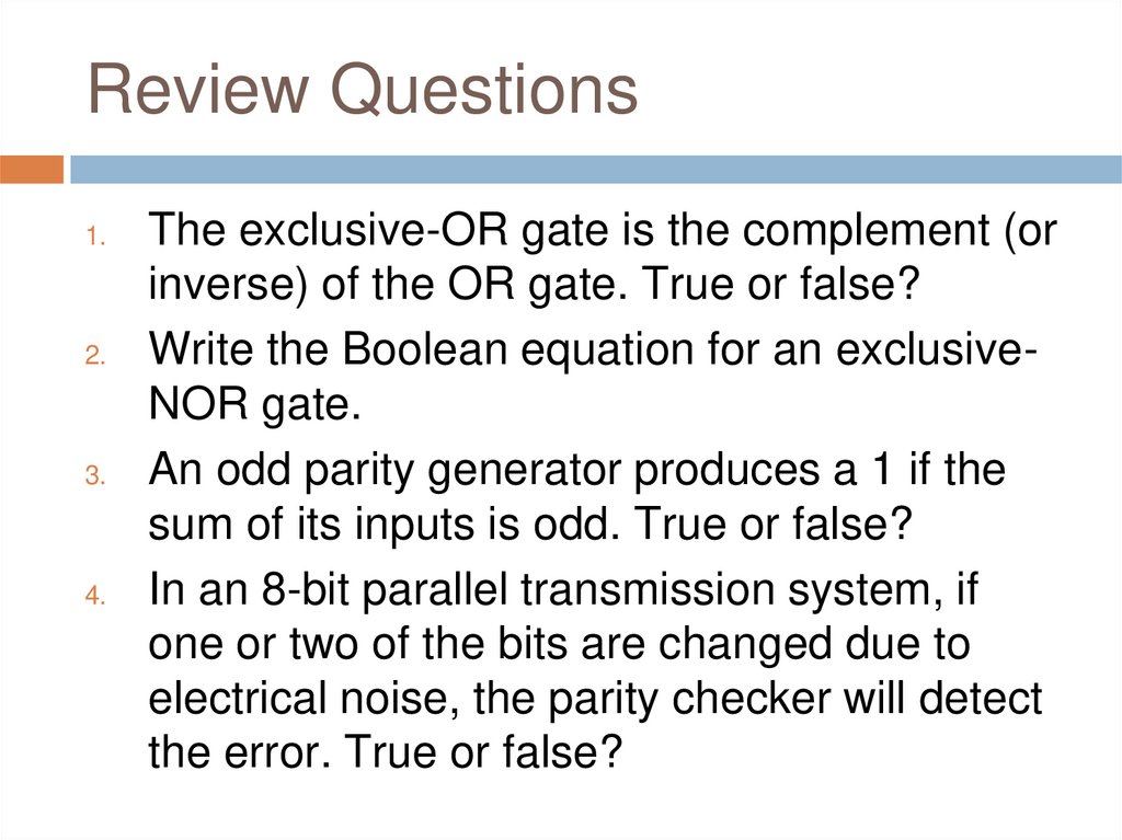
Review Questions1.
2.
3.
4.
The exclusive-OR gate is the complement (or
inverse) of the OR gate. True or false?
Write the Boolean equation for an exclusiveNOR gate.
An odd parity generator produces a 1 if the
sum of its inputs is odd. True or false?
In an 8-bit parallel transmission system, if
one or two of the bits are changed due to
electrical noise, the parity checker will detect
the error. True or false?
11.
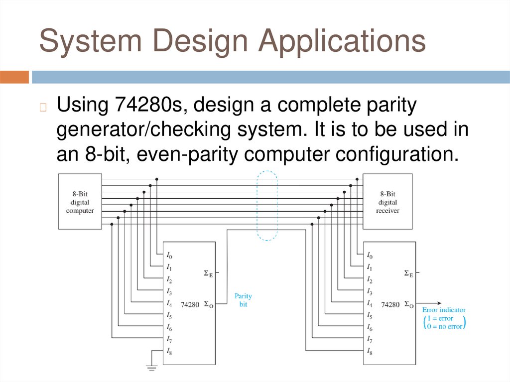
System Design Applications◻
Using 74280s, design a complete parity
generator/checking system. It is to be used in
an 8-bit, even-parity computer configuration.
12.
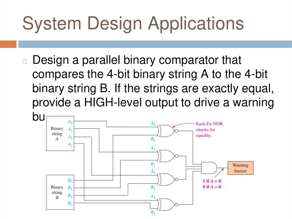
System Design Applications◻
Design a parallel binary comparator that
compares the 4-bit binary string A to the 4-bit
binary string B. If the strings are exactly equal,
provide a HIGH-level output to drive a warning
buzzer.
13.
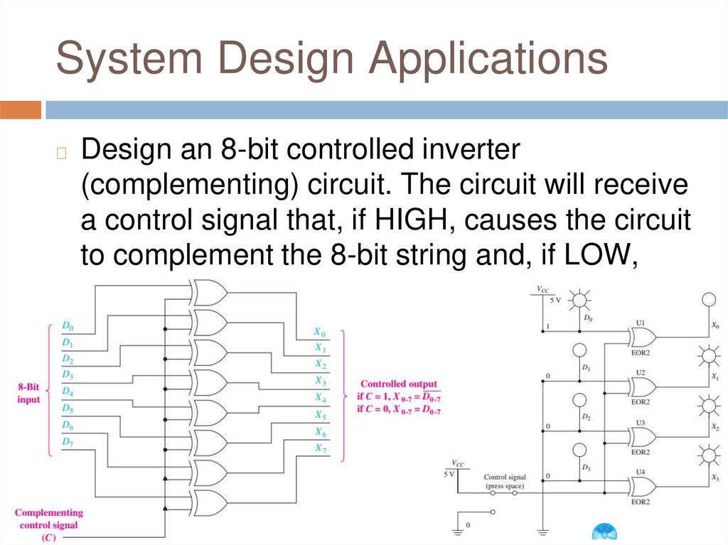
System Design Applications◻
Design an 8-bit controlled inverter
(complementing) circuit. The circuit will receive
a control signal that, if HIGH, causes the circuit
to complement the 8-bit string and, if LOW,
does not.
14.
FPGA Design Applications◻
new concepts related to FPGAs
◻ define an internal signal
◻ group the inputs together as a vector
◻ Selected Signal Assignment
7400-series macro-functions
◻ grouping nodes into a common bus
◻ changing a group’s radix
◻ creating a VHDL Process Statement
◻ For Loop
◻
15.
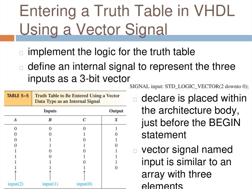
Entering a Truth Table in VHDLUsing a Vector Signal
implement the logic for the truth table
◻ define an internal signal to represent the three
inputs as a 3-bit vector
◻
declare is placed within
the architecture body,
just before the BEGIN
statement
◻ vector signal named
input is similar to an
array with three
◻
16.
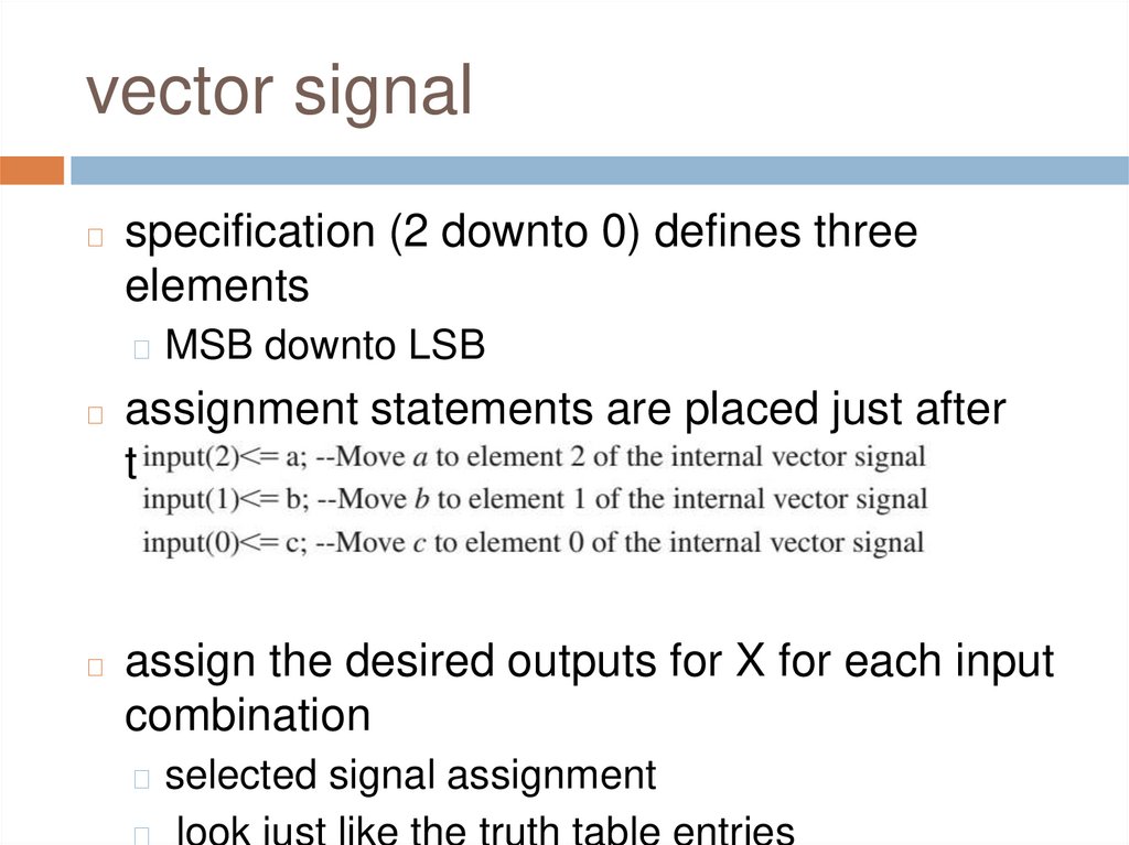
vector signal◻
specification (2 downto 0) defines three
elements
◻ MSB downto LSB
◻
assignment statements are placed just after
the BEGIN statement
◻
assign the desired outputs for X for each input
combination
◻ selected signal assignment
◻
look just like the truth table entries
17.
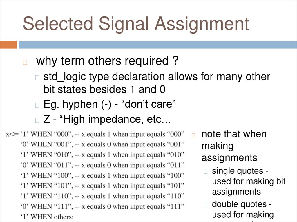
Selected Signal Assignment◻
why term others required ?
◻ std_logic type declaration allows for many other
bit states besides 1 and 0
◻ Eg. hyphen (-) - “don’t care”
◻ Z - “High impedance, etc…
◻
note that when
making
assignments
◻ single quotes -
used for making bit
assignments
◻ double quotes used for making
18.
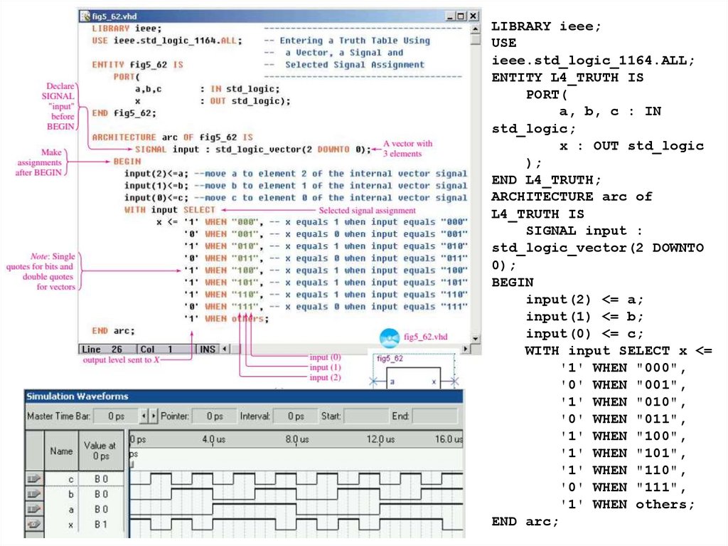
LIBRARY ieee;USE
ieee.std_logic_1164.ALL;
ENTITY L4_TRUTH IS
PORT(
a, b, c : IN
std_logic;
x : OUT std_logic
);
END L4_TRUTH;
ARCHITECTURE arc of
L4_TRUTH IS
SIGNAL input :
std_logic_vector(2 DOWNTO
0);
BEGIN
input(2) <= a;
input(1) <= b;
input(0) <= c;
WITH input SELECT x <=
'1' WHEN "000",
'0' WHEN "001",
'1' WHEN "010",
'0' WHEN "011",
'1' WHEN "100",
'1' WHEN "101",
'1' WHEN "110",
'0' WHEN "111",
'1' WHEN others;
END arc;
19.
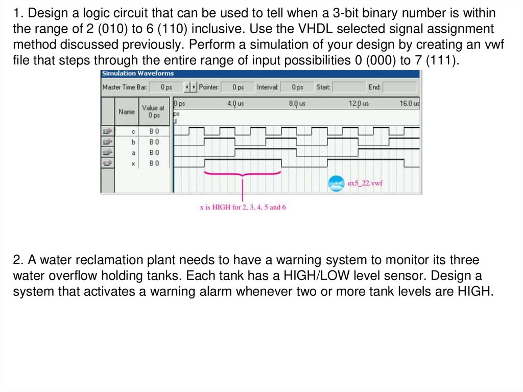
1. Design a logic circuit that can be used to tell when a 3-bit binary number is withinthe range of 2 (010) to 6 (110) inclusive. Use the VHDL selected signal assignment
method discussed previously. Perform a simulation of your design by creating an vwf
file that steps through the entire range of input possibilities 0 (000) to 7 (111).
2. A water reclamation plant needs to have a warning system to monitor its three
water overflow holding tanks. Each tank has a HIGH/LOW level sensor. Design a
system that activates a warning alarm whenever two or more tank levels are HIGH.
20.
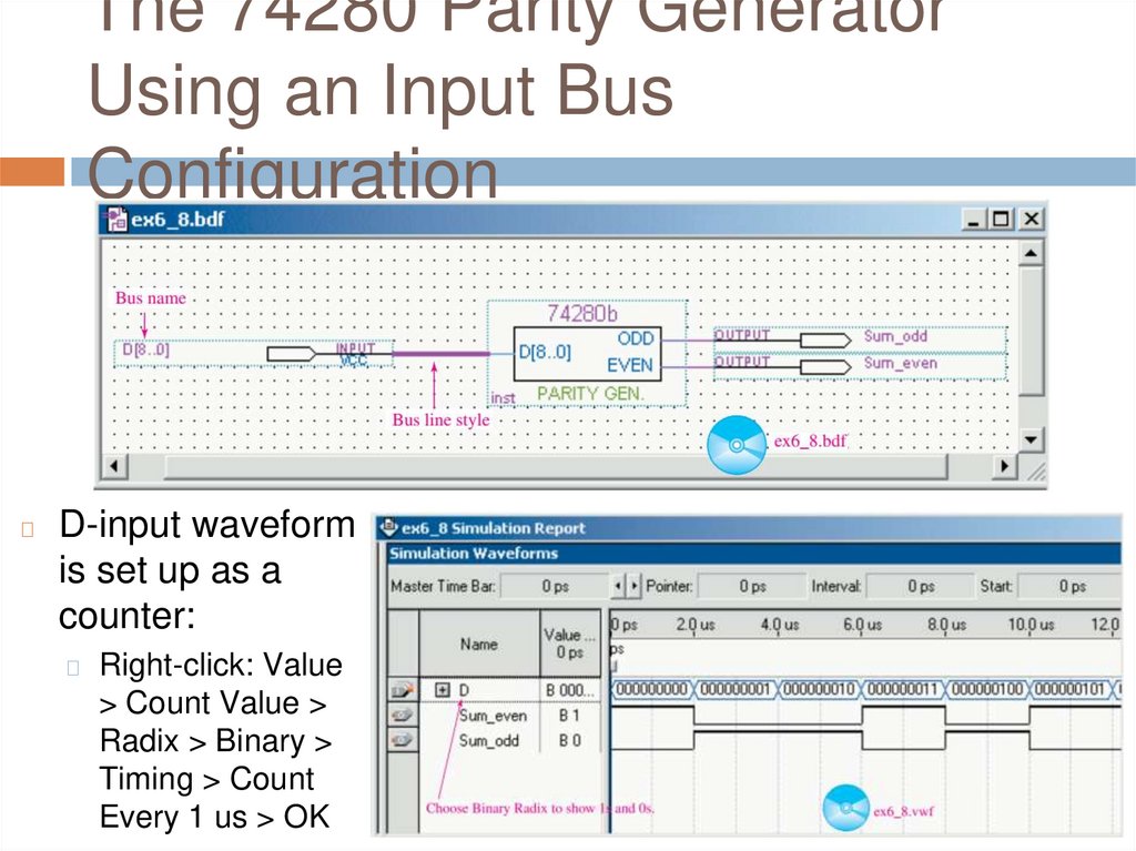
The 74280 Parity GeneratorUsing an Input Bus
Configuration
◻
D-input waveform
is set up as a
counter:
◻
Right-click: Value
> Count Value >
Radix > Binary >
Timing > Count
Every 1 us > OK
21.
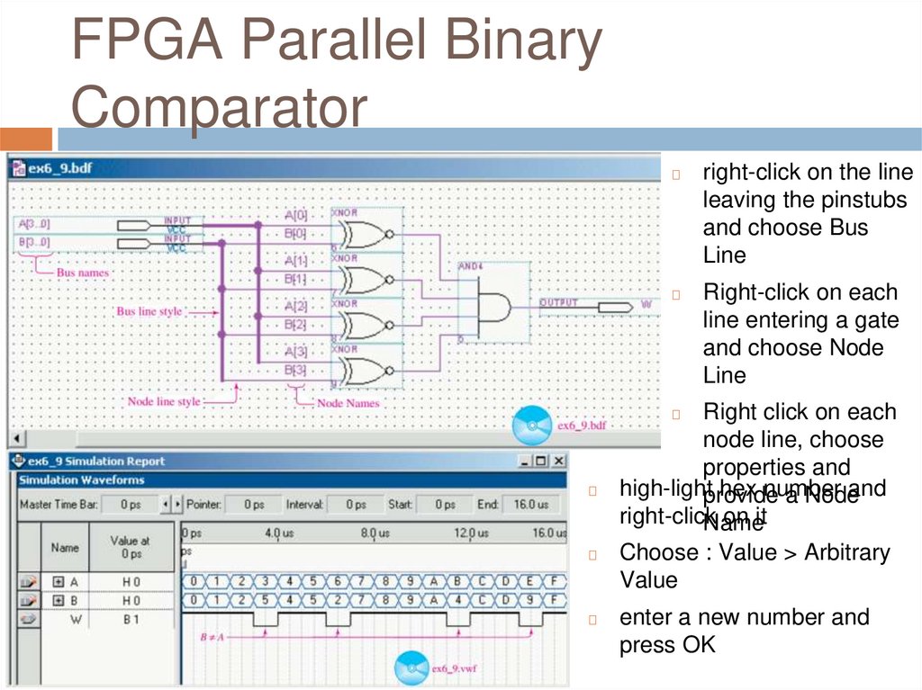
FPGA Parallel BinaryComparator
◻
right-click on the line
leaving the pinstubs
and choose Bus
Line
◻
Right-click on each
line entering a gate
and choose Node
Line
Right click on each
node line, choose
properties and
high-lightprovide
hex number
and
a Node
right-click
on it
Name
Choose : Value > Arbitrary
Value
◻
◻
◻
◻
enter a new number and
press OK
22.
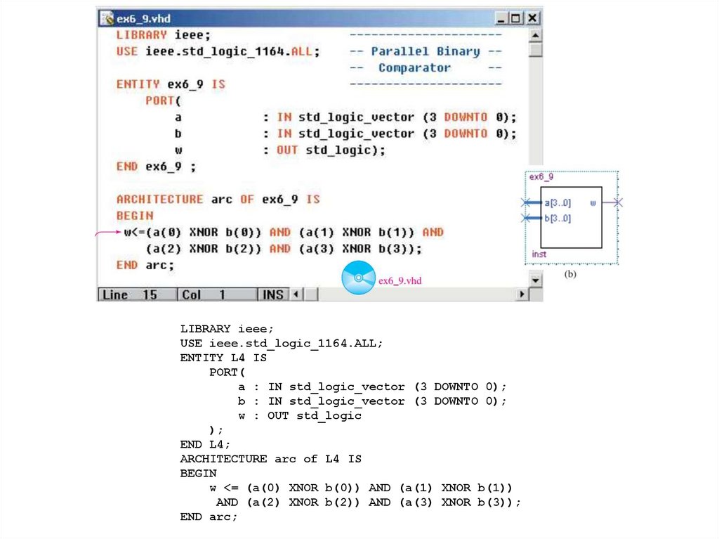
LIBRARY ieee;USE ieee.std_logic_1164.ALL;
ENTITY L4 IS
PORT(
a : IN std_logic_vector (3 DOWNTO 0);
b : IN std_logic_vector (3 DOWNTO 0);
w : OUT std_logic
);
END L4;
ARCHITECTURE arc of L4 IS
BEGIN
w <= (a(0) XNOR b(0)) AND (a(1) XNOR b(1))
AND (a(2) XNOR b(2)) AND (a(3) XNOR b(3));
END arc;
23.
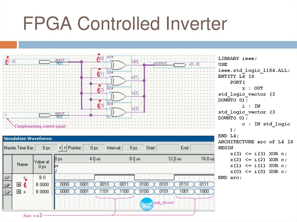
FPGA Controlled InverterLIBRARY ieee;
USE
ieee.std_logic_1164.ALL;
ENTITY L4 IS
PORT(
x : OUT
std_logic_vector (3
DOWNTO 0);
i : IN
std_logic_vector (3
DOWNTO 0);
c : IN std_logic
);
END L4;
ARCHITECTURE arc of L4 IS
BEGIN
x(3) <= i(3) XOR c;
x(2) <= i(2) XOR c;
x(1) <= i(1) XOR c;
x(0) <= i(0) XOR c;
END arc;
24.
25.
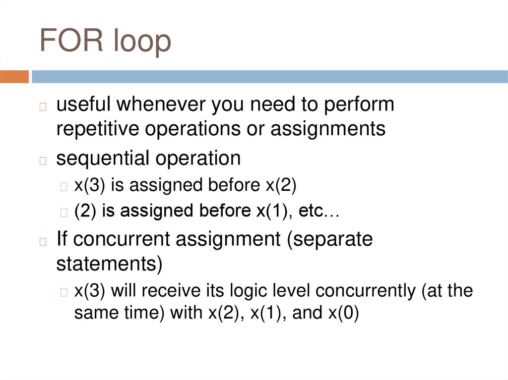
FOR loopuseful whenever you need to perform
repetitive operations or assignments
◻ sequential operation
◻
◻ x(3) is assigned before x(2)
◻ (2) is assigned before x(1), etc…
◻
If concurrent assignment (separate
statements)
◻ x(3) will receive its logic level concurrently (at the
same time) with x(2), x(1), and x(0)
26.
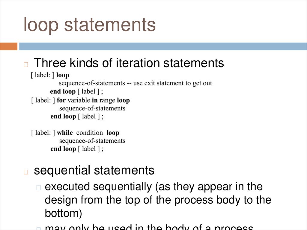
loop statements◻
Three kinds of iteration statements
◻
sequential statements
◻ executed sequentially (as they appear in the
design from the top of the process body to the
bottom)
27.
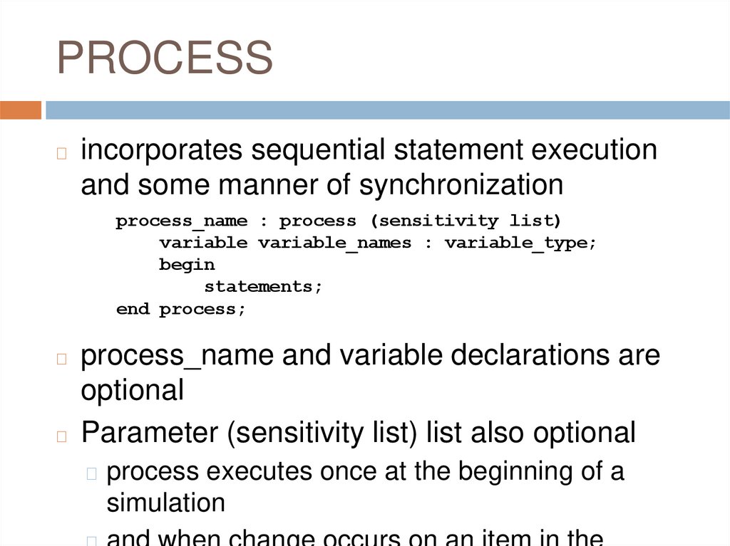
PROCESS◻
incorporates sequential statement execution
and some manner of synchronization
process_name : process (sensitivity list)
variable variable_names : variable_type;
begin
statements;
end process;
process_name and variable declarations are
optional
◻ Parameter (sensitivity list) list also optional
◻
◻ process executes once at the beginning of a
simulation
28.
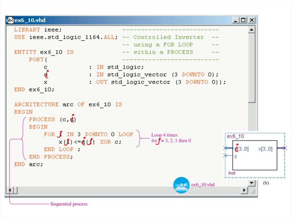
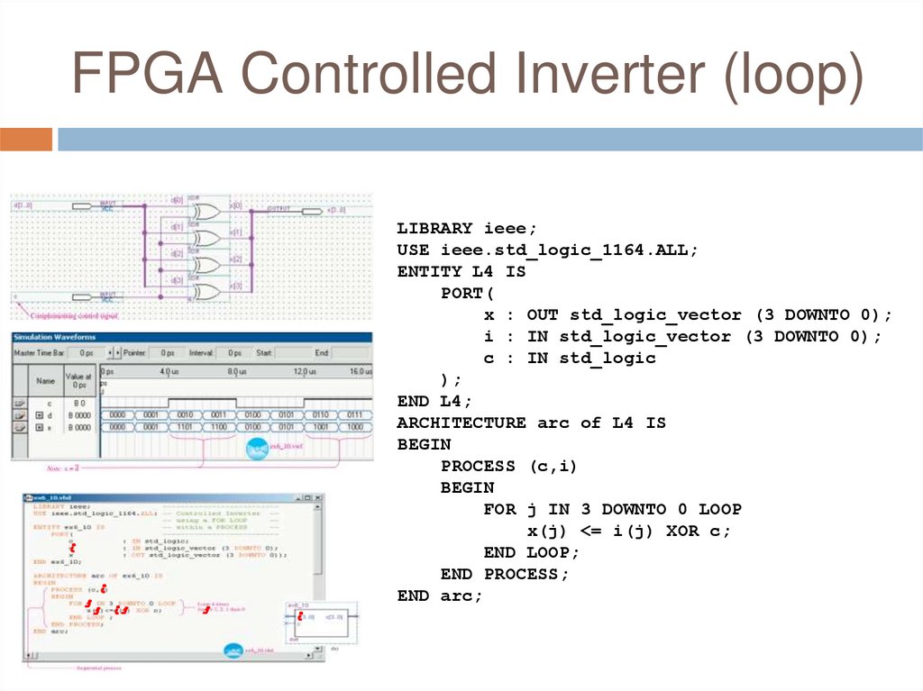
FPGA Controlled Inverter (loop)LIBRARY ieee;
USE ieee.std_logic_1164.ALL;
ENTITY L4 IS
PORT(
x : OUT std_logic_vector (3 DOWNTO 0);
i : IN std_logic_vector (3 DOWNTO 0);
c : IN std_logic
);
END L4;
ARCHITECTURE arc of L4 IS
BEGIN
PROCESS (c,i)
BEGIN
FOR j IN 3 DOWNTO 0 LOOP
x(j) <= i(j) XOR c;
END LOOP;
END PROCESS;
END arc;
29.
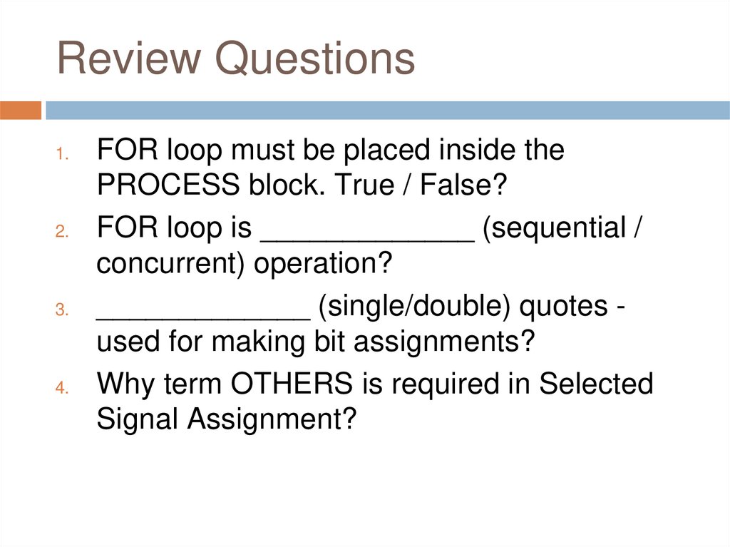
Review Questions1.
2.
3.
4.
FOR loop must be placed inside the
PROCESS block. True / False?
FOR loop is _____________ (sequential /
concurrent) operation?
_____________ (single/double) quotes used for making bit assignments?
Why term OTHERS is required in Selected
Signal Assignment?
30.
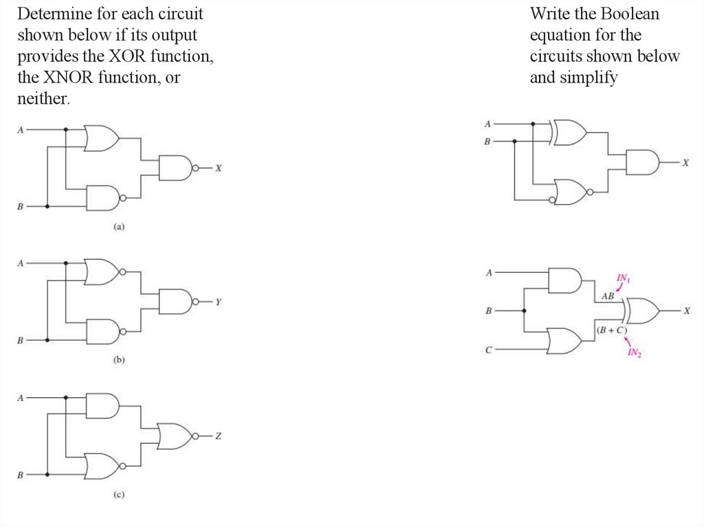
Determine for each circuitshown below if its output
provides the XOR function,
the XNOR function, or
neither.
Write the Boolean
equation for the
circuits shown below
and simplify
31.
Q&AAny Questions?