

 electronics
Similar presentations:


")


 damper")

DATC -Dual Automatic Temperature Control -
1.
DATC-Dual Automatic Temperature Control -
Copyright ⓒ 2009 All rights reserved. No part of this material may be reproduced, stored in any retrieval system or transmitted in any form or by any means without the written permission of Hyundai Motor Company.
2.
DATC2
General Specification
Item
Tuscan (JM)
LM
Compressor
Internal variable capacity swash plate type
(10PA17/10PA19)
External variable capacity swash plate type
(DVE16)
Cluster ionizer
Not applied
Applied
Fin thermo sensor
Evaporator core insertion type
Air detection type
(Surface temp. detection)
External temp. sensor and AQS sensor
separable
External temp. sensor (AQS sensor removed)
Interior temp. sensor and humidity sensor
combined
(ACTIVE MOTOR TYPE)
Independent type (Humidity sensor removed)
(Aspirator type)
Independent type
Photo sensor and solar radiation sensor combined
(Dual solar radiation sensor applied)
Coolant temp. sensor applied
Coolant temp. sensor not applied
(Engine coolant temp. sensor shared)
Temp. actuator (F/B type)
F/B type (Built-in position sensor)
Mode actuator (F/B type)
F/B type (Built-in position sensor)
Intake actuator
F/B type (Built-in position sensor)
Full automatic air
conditioning (DATC)
Copyright ⓒ 2009 All rights reserved. No part of this material may be reproduced, stored in any retrieval system or transmitted in any form or by any means without the written permission of Hyundai Motor Company.
3.
DATC3
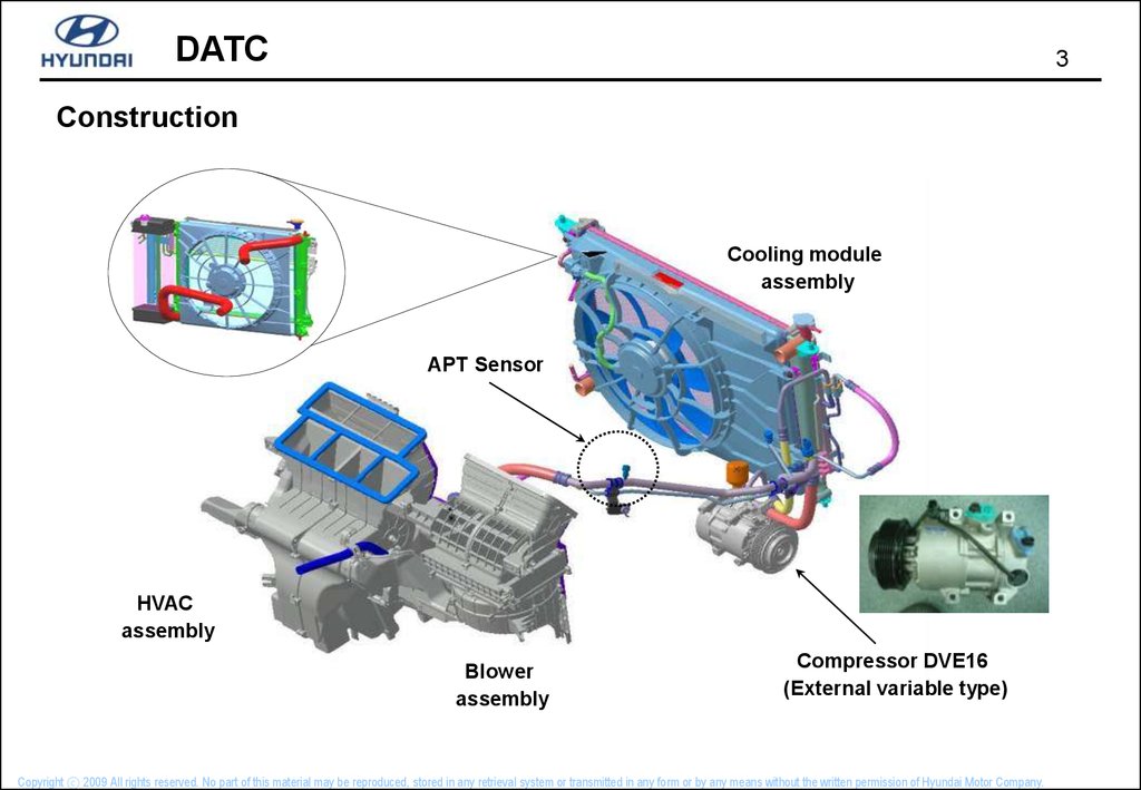
Construction
Cooling module
assembly
APT Sensor
HVAC
assembly
Blower
assembly
Compressor DVE16
(External variable type)
Copyright ⓒ 2009 All rights reserved. No part of this material may be reproduced, stored in any retrieval system or transmitted in any form or by any means without the written permission of Hyundai Motor Company.
4.
DATC4
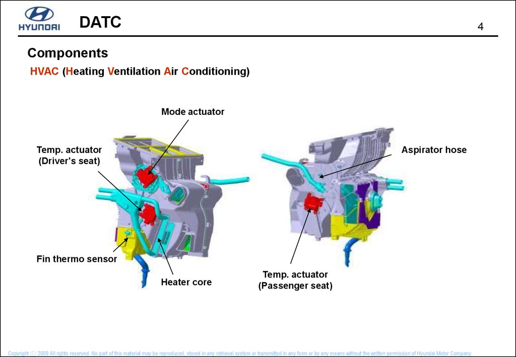
Components
HVAC (Heating Ventilation Air Conditioning)
Mode actuator
Aspirator hose
Temp. actuator
(Driver's seat)
Fin thermo sensor
Heater core
Temp. actuator
(Passenger seat)
Copyright ⓒ 2009 All rights reserved. No part of this material may be reproduced, stored in any retrieval system or transmitted in any form or by any means without the written permission of Hyundai Motor Company.
5.
DATC5
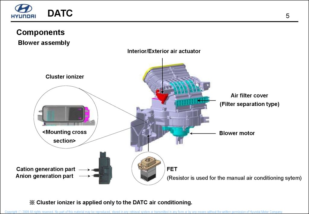
Components
Blower assembly
Interior/Exterior air actuator
Cluster ionizer
Air filter cover
(Filter separation type)
<Mounting cross
Blower motor
section>
Cation generation part
Anion generation part
FET
(Resistor is used for the manual air conditioning sytem)
※ Cluster ionizer is applied only to the DATC air conditioning.
Copyright ⓒ 2009 All rights reserved. No part of this material may be reproduced, stored in any retrieval system or transmitted in any form or by any means without the written permission of Hyundai Motor Company.
6.
DATC6
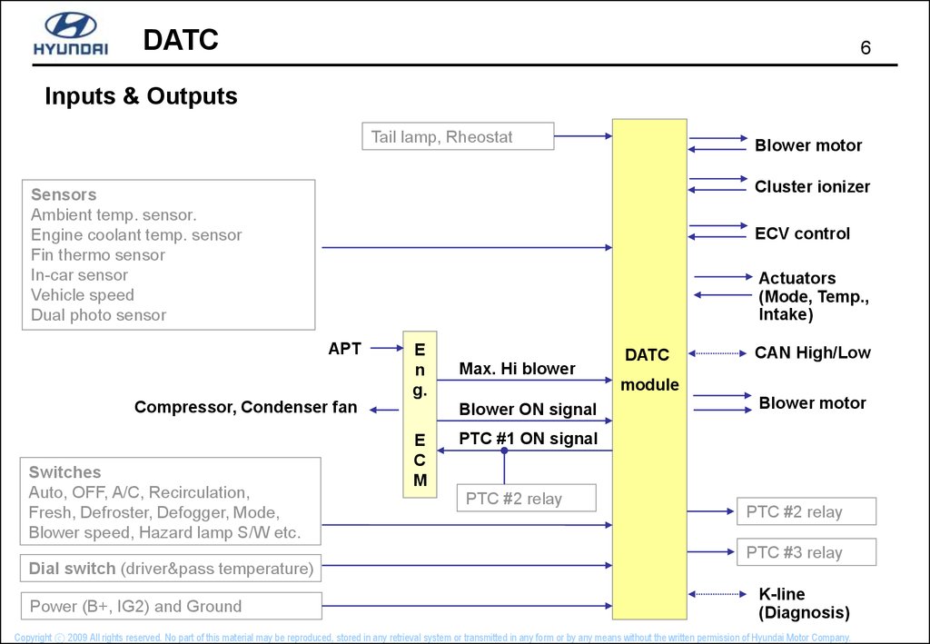
Inputs & Outputs
Tail lamp, Rheostat
Blower motor
Cluster ionizer
Sensors
Ambient temp. sensor.
Engine coolant temp. sensor
Fin thermo sensor
In-car sensor
Vehicle speed
Dual photo sensor
ECV control
Actuators
(Mode, Temp.,
Intake)
APT
E
n
g.
Compressor, Condenser fan
Switches
Auto, OFF, A/C, Recirculation,
Fresh, Defroster, Defogger, Mode,
Blower speed, Hazard lamp S/W etc.
Max. Hi blower
CAN High/Low
module
Blower ON signal
E
C
M
DATC
Blower motor
PTC #1 ON signal
PTC #2 relay
PTC #2 relay
PTC #3 relay
Dial switch (driver&pass temperature)
Power (B+, IG2) and Ground
K-line
(Diagnosis)
Copyright ⓒ 2009 All rights reserved. No part of this material may be reproduced, stored in any retrieval system or transmitted in any form or by any means without the written permission of Hyundai Motor Company.
7.
DATC7
Inputs & Outputs
Tail lamp, Rheostat
Blower motor
Cluster ionizer
Sensors
Ambient temp. sensor.
Engine coolant temp. sensor
Fin thermo sensor
In-car sensor
Vehicle speed
Dual photo sensor
ECV control
Actuators
(Mode, Temp.,
Intake)
APT
E
n
g.
Compressor, Condenser fan
Switches
Auto, OFF, A/C, Recirculation,
Fresh, Defroster, Defogger, Mode,
Blower speed, Hazard lamp S/W etc.
Max. Hi blower
CAN High/Low
module
Blower ON signal
E
C
M
DATC
Blower motor
PTC #1 ON signal
PTC #2 relay
PTC #2 relay
PTC #3 relay
Dial switch (driver&pass temperature)
Power (B+, IG2) and Ground
K-line
(Diagnosis)
Copyright ⓒ 2009 All rights reserved. No part of this material may be reproduced, stored in any retrieval system or transmitted in any form or by any means without the written permission of Hyundai Motor Company.
8.
DATC8
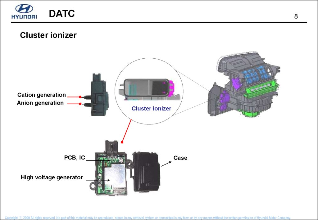
Cluster ionizer
Cation generation
Anion generation
Cluster ionizer
PCB, IC
Case
High voltage generator
Copyright ⓒ 2009 All rights reserved. No part of this material may be reproduced, stored in any retrieval system or transmitted in any form or by any means without the written permission of Hyundai Motor Company.
9.
DATC9
Cluster ionizer
Cluster ionizer mode
Ion mode
Signals
(-) ion
activation
Clean
mode
IG 2
ION signal
OFF
(+,-) ion
activation
CLEAN signal
Control Unit
ION signal
HI (12V)
LOW (0V)
LOW (0V)
CLEAN
signal
HI (12V)
HI (12V)
LOW (0V)
Diagnosis signal
Ionizer
Ground
CLEAN mode : CLEAN display
ION mode : ION display
Cluster ionizer operating lamp
Copyright ⓒ 2009 All rights reserved. No part of this material may be reproduced, stored in any retrieval system or transmitted in any form or by any means without the written permission of Hyundai Motor Company.
10.
DATC10
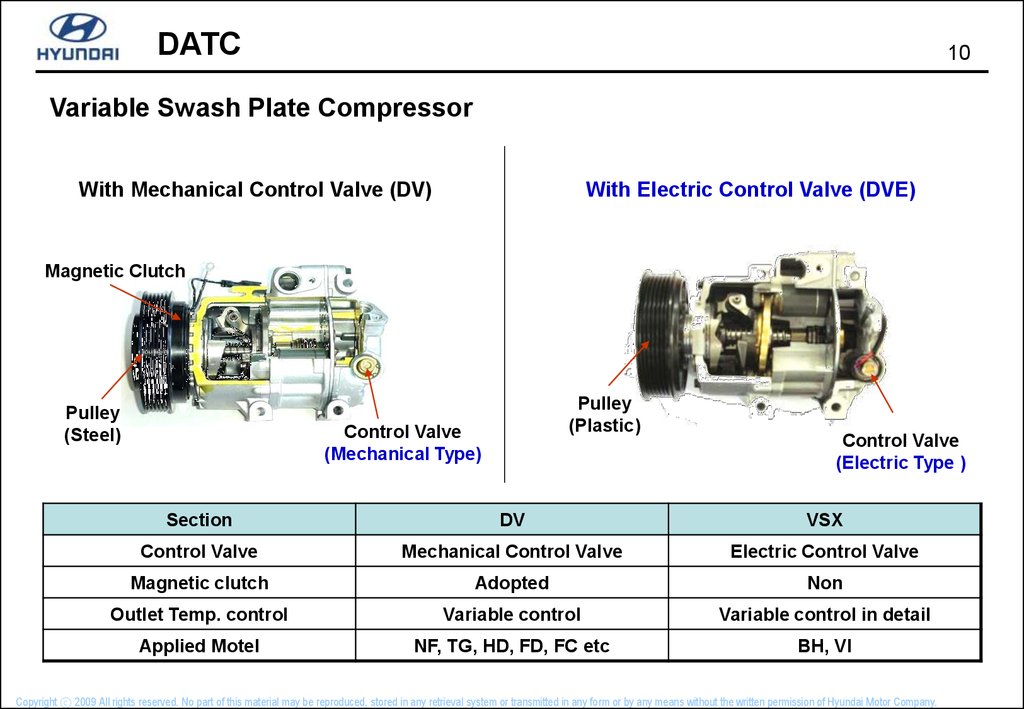
Variable Swash Plate Compressor
With Mechanical Control Valve (DV)
With Electric Control Valve (DVE)
Magnetic Clutch
Pulley
(Steel)
Pulley
(Plastic)
Control Valve
(Mechanical Type)
Control Valve
(Electric Type )
Section
DV
VSX
Control Valve
Mechanical Control Valve
Electric Control Valve
Magnetic clutch
Adopted
Non
Outlet Temp. control
Variable control
Variable control in detail
Applied Motel
NF, TG, HD, FD, FC etc
BH, VI
Copyright ⓒ 2009 All rights reserved. No part of this material may be reproduced, stored in any retrieval system or transmitted in any form or by any means without the written permission of Hyundai Motor Company.
11.
DATC11
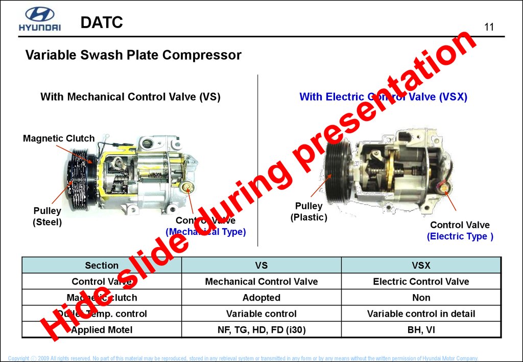
Variable Swash Plate Compressor
With Mechanical Control Valve (VS)
With Electric Control Valve (VSX)
Magnetic Clutch
Pulley
(Steel)
Pulley
(Plastic)
Control Valve
(Mechanical Type)
Control Valve
(Electric Type )
Section
VS
VSX
Control Valve
Mechanical Control Valve
Electric Control Valve
Magnetic clutch
Adopted
Non
Outlet Temp. control
Variable control
Variable control in detail
Applied Motel
NF, TG, HD, FD (i30)
BH, VI
Copyright ⓒ 2009 All rights reserved. No part of this material may be reproduced, stored in any retrieval system or transmitted in any form or by any means without the written permission of Hyundai Motor Company.
12.
DATC12
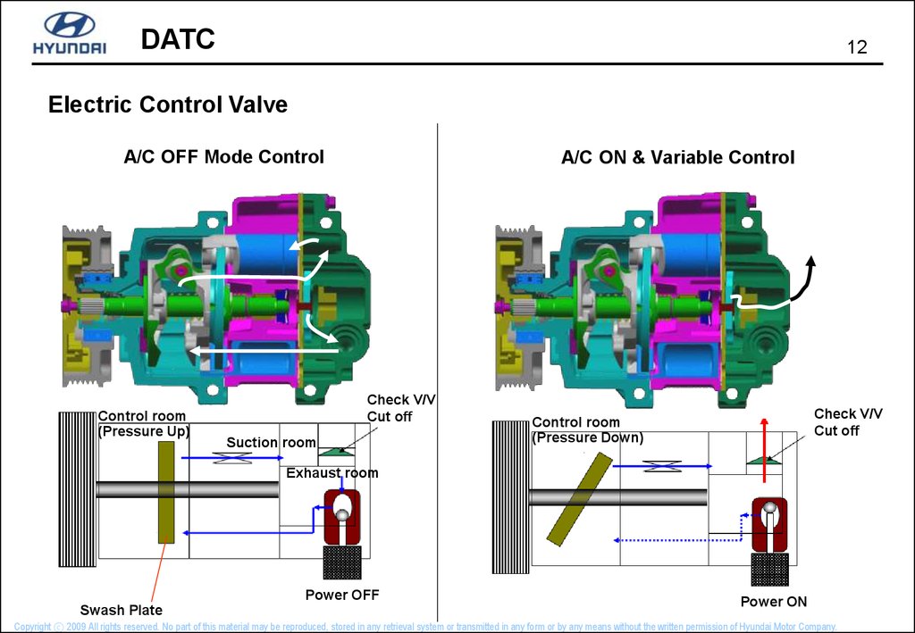
Electric Control Valve
A/C OFF Mode Control
Control room
(Pressure Up)
A/C ON & Variable Control
Check V/V
Cut off
Suction room
Check V/V
Cut off
Control room
(Pressure Down)
Exhaust room
Power OFF
Swash Plate
Power ON
Copyright ⓒ 2009 All rights reserved. No part of this material may be reproduced, stored in any retrieval system or transmitted in any form or by any means without the written permission of Hyundai Motor Company.
13.
DATC13
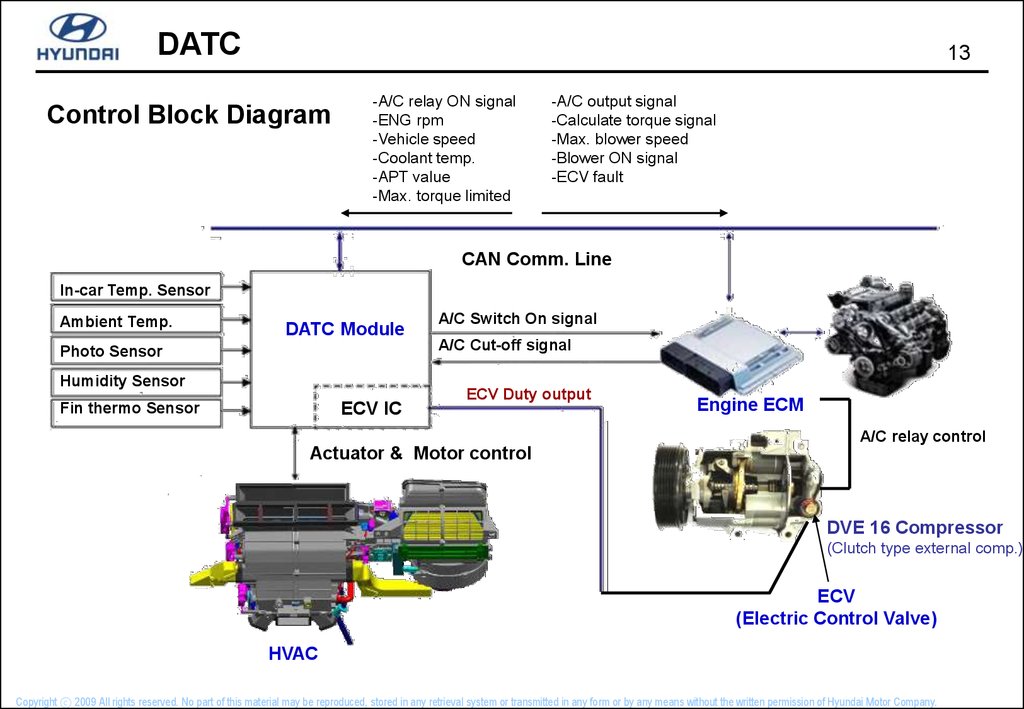
Control Block Diagram
-A/C relay ON signal
-ENG rpm
-Vehicle speed
-Coolant temp.
-APT value
-Max. torque limited
-A/C output signal
-Calculate torque signal
-Max. blower speed
-Blower ON signal
-ECV fault
CAN Comm. Line
In-car Temp. Sensor
Ambient Temp.
DATC Module
A/C Switch On signal
A/C Cut-off signal
Photo Sensor
Humidity Sensor
ECV IC
Fin thermo Sensor
ECV Duty output
Engine ECM
A/C relay control
Actuator & Motor control
DVE 16 Compressor
(Clutch type external comp.)
ECV
(Electric Control Valve)
HVAC
Copyright ⓒ 2009 All rights reserved. No part of this material may be reproduced, stored in any retrieval system or transmitted in any form or by any means without the written permission of Hyundai Motor Company.
14.
DATC14
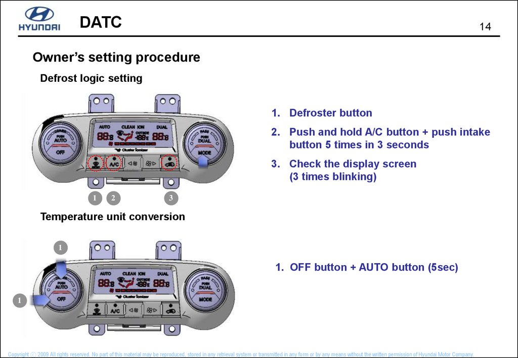
Owner’s setting procedure
Defrost logic setting
1. Defroster button
2. Push and hold A/C button + push intake
button 5 times in 3 seconds
3. Check the display screen
(3 times blinking)
1
2
3
Temperature unit conversion
1
1. OFF button + AUTO button (5sec)
1
Copyright ⓒ 2009 All rights reserved. No part of this material may be reproduced, stored in any retrieval system or transmitted in any form or by any means without the written permission of Hyundai Motor Company.
15.
DATC15
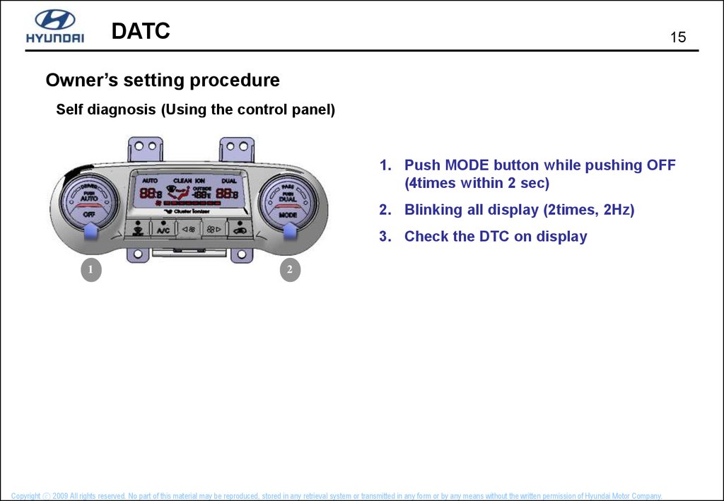
Owner’s setting procedure
Self diagnosis (Using the control panel)
1. Push MODE button while pushing OFF
(4times within 2 sec)
2. Blinking all display (2times, 2Hz)
3. Check the DTC on display
1
2
Copyright ⓒ 2009 All rights reserved. No part of this material may be reproduced, stored in any retrieval system or transmitted in any form or by any means without the written permission of Hyundai Motor Company.
16.
DATC16
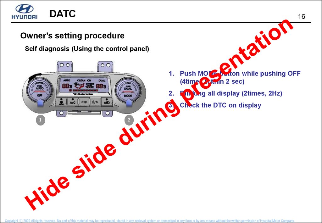
Owner’s setting procedure
Self diagnosis (Using the control panel)
1. Push MODE button while pushing OFF
(4times within 2 sec)
2. Blinking all display (2times, 2Hz)
3. Check the DTC on display
1
2
Copyright ⓒ 2009 All rights reserved. No part of this material may be reproduced, stored in any retrieval system or transmitted in any form or by any means without the written permission of Hyundai Motor Company.
17.
DATC17
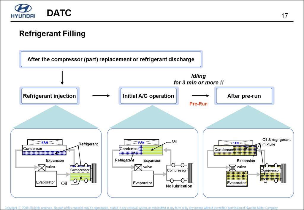
Refrigerant Filling
After the compressor (part) replacement or refrigerant discharge
Idling
for 3 min or more !!
Refrigerant injection
Initial A/C operation
After pre-run
Pre-Run
Condenser
Condenser
Refrigerant
Expansion
valve
Evaporator
Compressor
Oil
Oil & regrigerant
mixture
Oil
Refrigerant
Condenser
Expansion
Expansion
valve
valve
Compressor
Evaporator
No lubrication
Compressor
Evaporator
Copyright ⓒ 2009 All rights reserved. No part of this material may be reproduced, stored in any retrieval system or transmitted in any form or by any means without the written permission of Hyundai Motor Company.