 electronics
Similar presentations:


Operation Manual of Temperature. Control Box
1.
Operation Manual of TemperatureControl Box
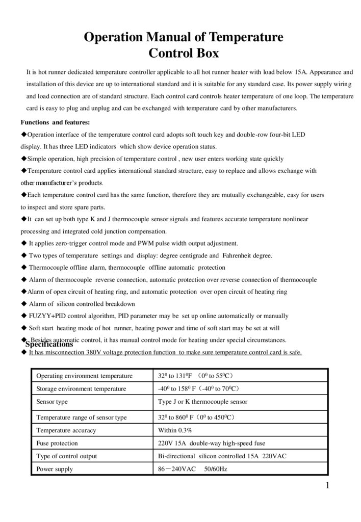
It is hot runner dedicated temperature controller applicable to all hot runner heater with load below 15A. Appearance and
installation of this device are up to international standard and it is suitable for any standard case. Its power supply wiring
and load connection are of standard structure. Each control card controls heater temperature of one loop. The temperature
card is easy to plug and unplug and can be exchanged with temperature card by other manufacturers.
Functions and features:
Operation interface of the temperature control card adopts soft touch key and double-row four-bit LED
display. It has three LED indicators which show device operation status.
Simple operation, high precision of temperature control , new user enters working state quickly
Temperature control card applies international standard structure, easy to replace and allows exchange with
other manufacturer’s products.
Each temperature control card has the same function, therefore they are mutually exchangeable, easy for users
to inspect and store spare parts.
It can set up both type K and J thermocouple sensor signals and features accurate temperature nonlinear
processing and integrated cold junction compensation.
It applies zero-trigger control mode and PWM pulse width output adjustment.
Two types of temperature settings and display: degree centigrade and Fahrenheit degree.
Thermocouple offline alarm, thermocouple offline automatic protection
Alarm of thermocouple reverse connection, automatic protection over reverse connection of thermocouple
Alarm of open circuit of heating ring, and automatic protection over open circuit of heating ring
Alarm of silicon controlled breakdown
FUZYY+PID control algorithm, PID parameter may be set up online automatically or manually
Soft start heating mode of hot runner, heating power and time of soft start may be set at will
Besides automatic control, it has manual control mode for heating under special circumstances.
Specifications
It has misconnection 380V voltage protection function to make sure temperature control card is safe.
Operating environment temperature
320 to 1310F 00 to 550C
Storage environment temperature
-400 to 1580 F -400 to 700C
Sensor type
Type J or K thermocouple sensor
Temperature range of sensor type
320 to 8600 F 00 to 4500C
Temperature accuracy
Within 0.3%
Fuse protection
220V 15A double-way high-speed fuse
Type of control output
Bi-directional silicon controlled 15A 220VAC
Power supply
86 240VAC
50/60Hz
1
2.
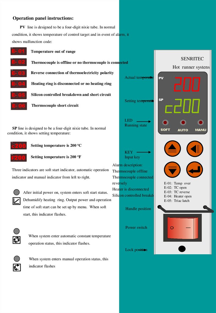
Operation panel instructions:PV line is designed to be a four-digit nixie tube. In normal
condition, it shows temperature of control target and in event of alarm, it
shows malfunction code:
E- 01
Temperature out of range
E- 02
Thermocouple is offline or no thermocouple is connected
E- 03
Reverse connection of thermoelectricity polarity
E- 04
Heating ring is disconnected or no heating ring
E- 05
Silicon controlled breakdown and short circuit
E- 06
Thermocouple short circuit
SENRITEC
Hot runner systens
Actual temperature PV
Setting temperature SP
SP line is designed to be a four-digit nixie tube. In normal
condition, it shows setting temperature:
LED
Running state
SOFT
AUTO
MANU
c200 Setting temperature is 200 ℃
F200
Setting temperature is 200 ℉
KEY
Input key
Alarm description:
Three indicators are soft start indicator, automatic operation Thermocouple offline
indicator and manual indicator from left to right.
Thermocouple connected
reversely
After initial power on, system enters soft start status.
Heater is disconnected
Silicon controlled breakdown
Dehumidify heating ring. Output power and operation
time of soft start can be set up by menu. When soft
E-01:
E-02:
E-03:
E-04:
E-05:
Temp over
TC open
TC reverse
Heater open
Triac latch
Handle position
start, this indicator flashes.
Power switch
When system enter automatic constant temperature
operation status, this indicator flashes.
Lock position
When system enters manual operation status, this
indicator flashes
2
3.
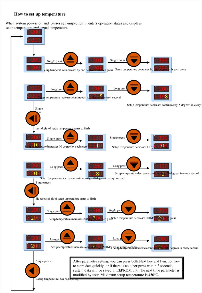
How to set up temperatureWhen system powers on and passes self-inspection, it enters operation status and displays
setup temperature and actual temperature:
200
c 200
200
c 200
201 Single press
200
c 201
c 200
degree with each press
Setup temperature increases by one degree
with each press Setup temperature decreases by one
Single press
Long press
200
Long press
200
c 200Setup temperature increases continuously, c5 degree
215in every second
200
c 198
Setup temperature decreases continuously, 5 degrees in every s
Single
press
tens digit of setup temperature starts to flash
200 Single press
210
c 200
Setup
temperature increases 10 degree by each press c 210
200
c 200
280
c 280
Long press
200
200
Setup temperature decreases 10 by c
each
press
Single press
120
Setup temperature decreases continuously, 50 degrees in every second
c 120
Long press
Setup temperature increases continuously, 50 degree in every second
Single press
Hundreds digit of setup temperature starts to flash
200
c 200
200
c 200
300 Single press
200
Setup temperature decreases 100 degree
by each press
Setup temperature increases 100 degree
by each press
c 300
c 200
Single press
Long press
450
000
Setup temperature increases continuously,
in every
seconddecreases continuously,
c 450 500 degree
c 000
Setup
temperature
500 degrees in every second
Long press
Single press
After parameter setting, you can press both Next key and Function key
to store data quickly, or if there is no other press within 3 seconds,
system data will be saved in EEPROM until the next time parameter is
modified by user. Maximum setup temperature is 450℃.
Setup temperature has no flash digit
3
4.
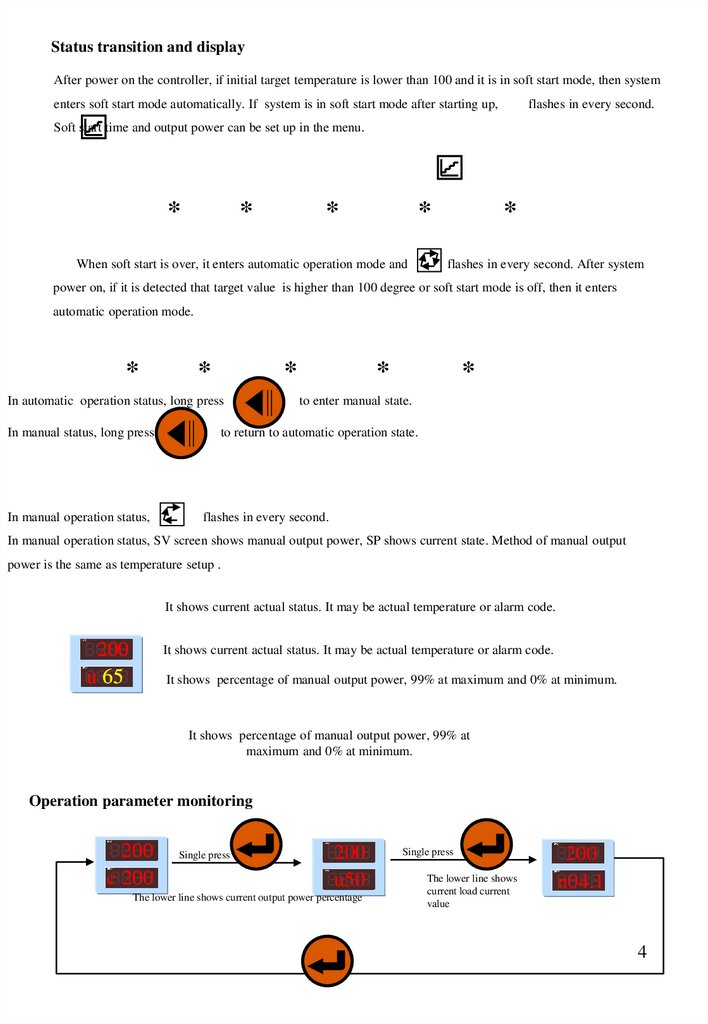
Status transition and displayAfter power on the controller, if initial target temperature is lower than 100 and it is in soft start mode, then system
enters soft start mode automatically. If system is in soft start mode after starting up,
flashes in every second.
Soft start time and output power can be set up in the menu.
*
*
*
*
When soft start is over, it enters automatic operation mode and
*
flashes in every second. After system
power on, if it is detected that target value is higher than 100 degree or soft start mode is off, then it enters
automatic operation mode.
*
*
*
In automatic operation status, long press
In manual status, long press
In manual operation status,
*
*
to enter manual state.
to return to automatic operation state.
flashes in every second.
In manual operation status, SV screen shows manual output power, SP shows current state. Method of manual output
power is the same as temperature setup .
It shows current actual status. It may be actual temperature or alarm code.
200
u 65
It shows current actual status. It may be actual temperature or alarm code.
It shows percentage of manual output power, 99% at maximum and 0% at minimum.
It shows percentage of manual output power, 99% at
maximum and 0% at minimum.
Operation parameter monitoring
200
c 200
Single press
200
u50
The lower line shows current output power percentage
Single press
The lower line shows
current load current
value
200
n04.1
4
5.
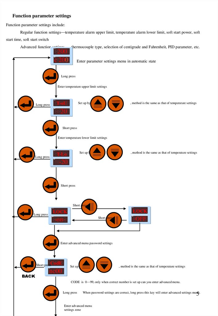
Function parameter settingsFunction parameter settings include:
Regular function settings—temperature alarm upper limit, temperature alarm lower limit, soft start power, soft
start time, soft start switch
Advanced function settings-----thermocouple type, selection of centigrade and Fahrenheit, PID parameter, etc.
200
c 200
Enter parameter settings menu in automatic state
Long press
Enter temperature upper limit settings
Long press
T-oU
Set up by
, method is the same as that of temperature settings
20
Short press
Enter temperature lower limit settings
Long press
Set up by
T-Lo
, method is the same as that of temperature settings
-20
Short press
Short press
Long press
LOCK
LOCK
Short press
-on-
-OFF
Enter advanced menu password settings
Short pressCodE
BACK
Set up by
, method is the same as that of temperature settings
nc00
CODE is 0—99, only when correct number is set up can you enter advanced menu.
Long press
When password settings are correct, long press this key will enter advanced settings menu.
Enter advanced menu
settings zone
5
6.
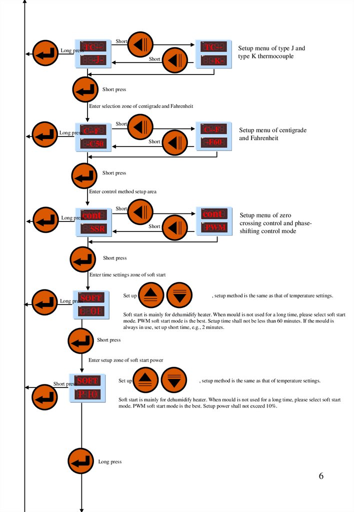
Short pressLong press TC--
-J-
TC-Short press
-K-
Setup menu of type J and
type K thermocouple
Short press
Enter selection zone of centigrade and Fahrenheit
Short press
C--F
Long press C--F
Short press
-C50
-F60
Setup menu of centigrade
and Fahrenheit
Short press
Enter control method setup area
Short press
cont
cont
Long press
Short press
SSR
PWM
Setup menu of zero
crossing control and phaseshifting control mode
Short press
Enter time settings zone of soft start
Set up by
Long pressSOFT
t. 01
, setup method is the same as that of temperature settings.
Soft start is mainly for dehumidify heater. When mould is not used for a long time, please select soft start
mode. PWM soft start mode is the best. Setup time shall not be less than 60 minutes. If the mould is
always in use, set up short time, e.g., 2 minutes.
Short press
Enter setup zone of soft start power
Short press SOFT
P 10
Set up by
, setup method is the same as that of temperature settings.
Soft start is mainly for dehumidify heater. When mould is not used for a long time, please select soft start
mode. PWM soft start mode is the best. Setup power shall not exceed 10%.
Long press
6
7.
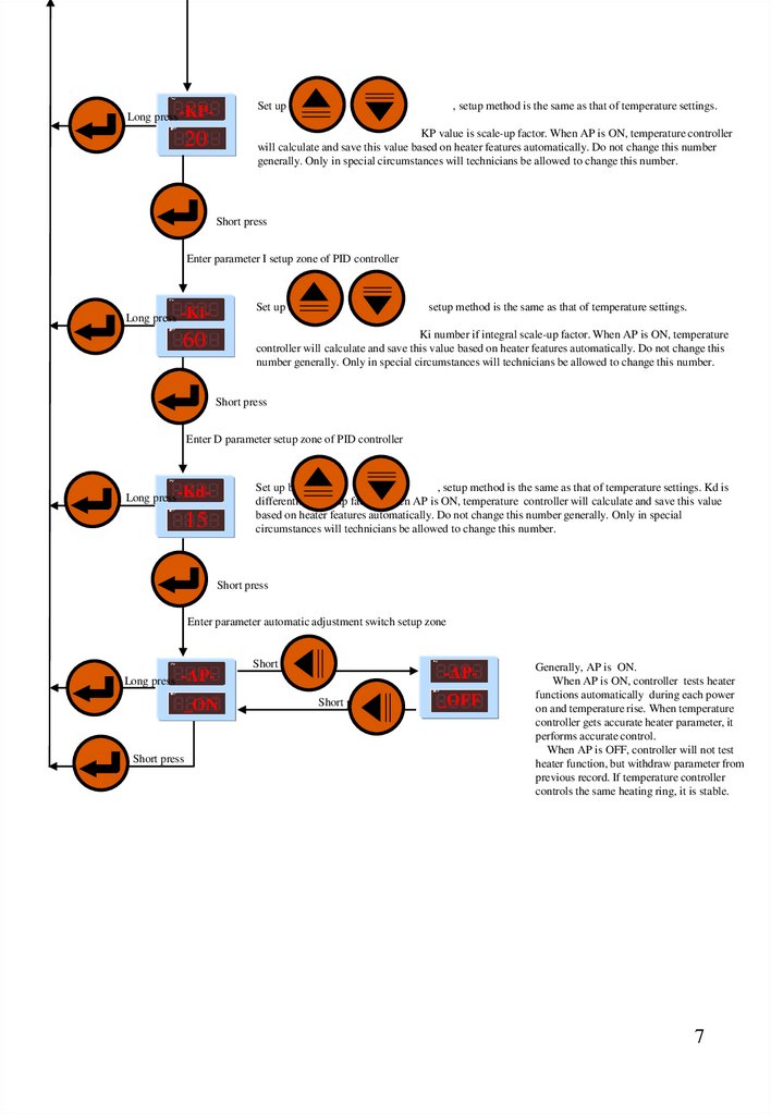
Set up by通过Long press -KP-
, setup method is the same as that of temperature settings.
KP value is scale-up factor. When AP is ON, temperature controller
will calculate and save this value based on heater features automatically. Do not change this number
generally. Only in special circumstances will technicians be allowed to change this number.
20
Short press
Enter parameter I setup zone of PID controller
Long press
-Ki-
Set up by
setup method is the same as that of temperature settings.
60
Ki number if integral scale-up factor. When AP is ON, temperature
controller will calculate and save this value based on heater features automatically. Do not change this
number generally. Only in special circumstances will technicians be allowed to change this number.
Short press
Enter D parameter setup zone of PID controller
Set up by
, setup method is the same as that of temperature settings. Kd is
differential scale-up factor. When AP is ON, temperature controller will calculate and save this value
based on heater features automatically. Do not change this number generally. Only in special
circumstances will technicians be allowed to change this number.
Long press-Kd-
15
Short press
Enter parameter automatic adjustment switch setup zone
Long press
-AP_ON
Short press
Short press
-APShort press
_OFF
Generally, AP is ON.
When AP is ON, controller tests heater
functions automatically during each power
on and temperature rise. When temperature
controller gets accurate heater parameter, it
performs accurate control.
When AP is OFF, controller will not test
heater function, but withdraw parameter from
previous record. If temperature controller
controls the same heating ring, it is stable.
7
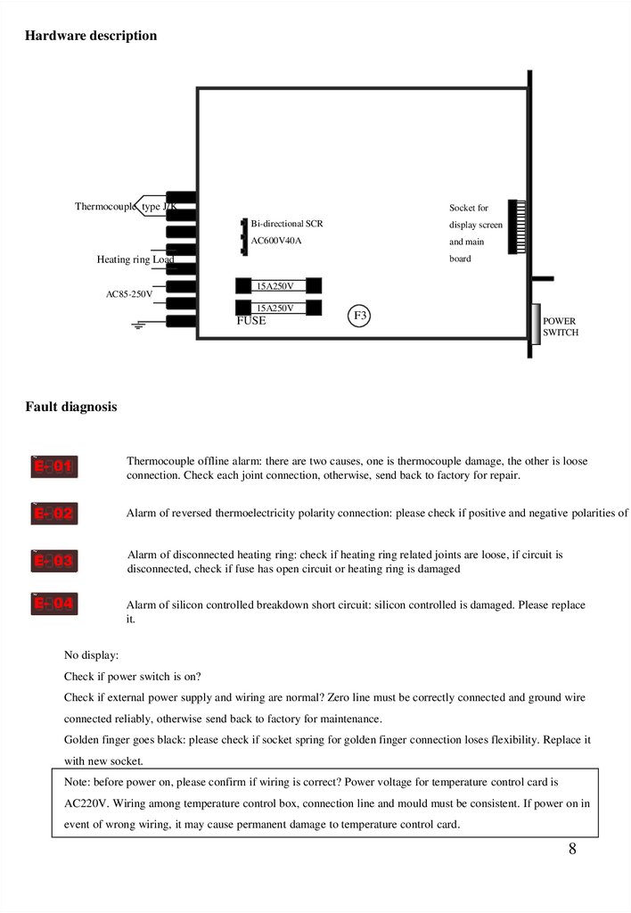
8.
Hardware descriptionThermocouple type J/K
+
_
Socket for
Bi-directional SCR
display screen
AC600V40A
and main
board
Heating ring Load
AC85-250V
15A250V
15A250V
FUSE
F3
POWER
SWITCH
Fault diagnosis
E- 01
Thermocouple offline alarm: there are two causes, one is thermocouple damage, the other is loose
connection. Check each joint connection, otherwise, send back to factory for repair.
E- 02
Alarm of reversed thermoelectricity polarity connection: please check if positive and negative polarities of t
E- 03
Alarm of disconnected heating ring: check if heating ring related joints are loose, if circuit is
disconnected, check if fuse has open circuit or heating ring is damaged
E- 04
Alarm of silicon controlled breakdown short circuit: silicon controlled is damaged. Please replace
it.
No display:
Check if power switch is on?
Check if external power supply and wiring are normal? Zero line must be correctly connected and ground wire
connected reliably, otherwise send back to factory for maintenance.
Golden finger goes black: please check if socket spring for golden finger connection loses flexibility. Replace it
with new socket.
Note: before power on, please confirm if wiring is correct? Power voltage for temperature control card is
AC220V. Wiring among temperature control box, connection line and mould must be consistent. If power on in
event of wrong wiring, it may cause permanent damage to temperature control card.
8