


 electronics
 advertising
Similar presentations:


Samsung Electronics
1.
Samsung ElectronicsThis Training Manual is a property of Samsung Electronics Co.,Ltd.
Any unauthorized use of Manual can be punished under applicable International and/or domestic law.
2.
Modification historyDate
Ver.
Modifier
Modified detail
22 Apr 16
0.0
Sungtae Kim
Made the original version of installation training materials
2/302
Remarks
This Document can not be used without Samsung's authorization
3.
4.
Process5.
Before start■ Things what should be checked before installation
5/302
This Document can not be used without Samsung's authorization
6.
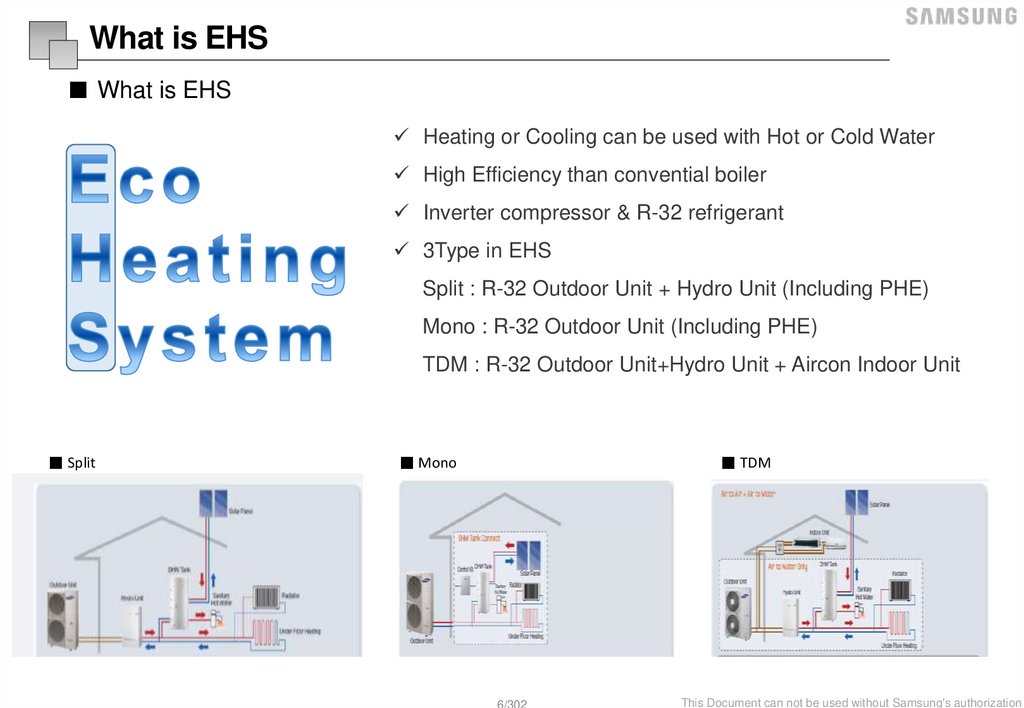
What is EHS■ What is EHS
Heating or Cooling can be used with Hot or Cold Water
High Efficiency than convential boiler
Inverter compressor & R-32 refrigerant
3Type in EHS
Split : R-32 Outdoor Unit + Hydro Unit (Including PHE)
Mono : R-32 Outdoor Unit (Including PHE)
TDM : R-32 Outdoor Unit+Hydro Unit + Aircon Indoor Unit
■ Split
■ Mono
■ TDM
6/302
This Document can not be used without Samsung's authorization
7.
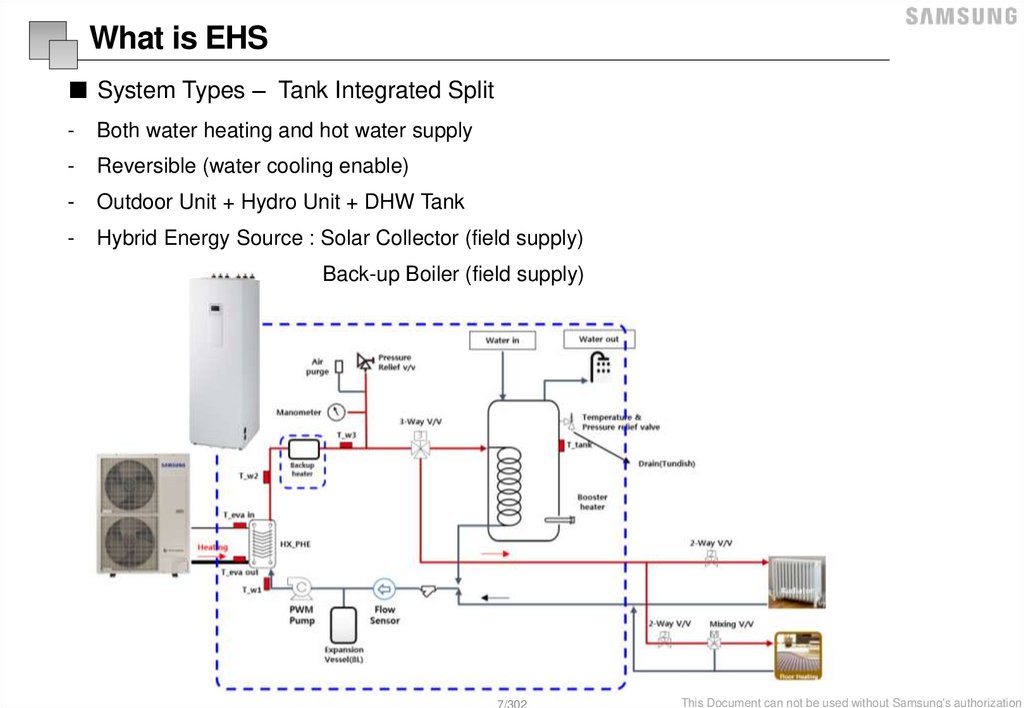
What is EHS■ System Types – Tank Integrated Split
-
Both water heating and hot water supply
-
Reversible (water cooling enable)
-
Outdoor Unit + Hydro Unit + DHW Tank
-
Hybrid Energy Source : Solar Collector (field supply)
Back-up Boiler (field supply)
7/302
This Document can not be used without Samsung's authorization
8.
What is EHS■ System Types – Tank Integrated Mono
-
Both water heating and hot water supply
-
Reversible (water cooling enable)
-
Mono Unit + DHW Tank
-
Hybrid Energy Source : Solar Collector (field supply)
Back-up Boiler (field supply)
8/302
This Document can not be used without Samsung's authorization
9.
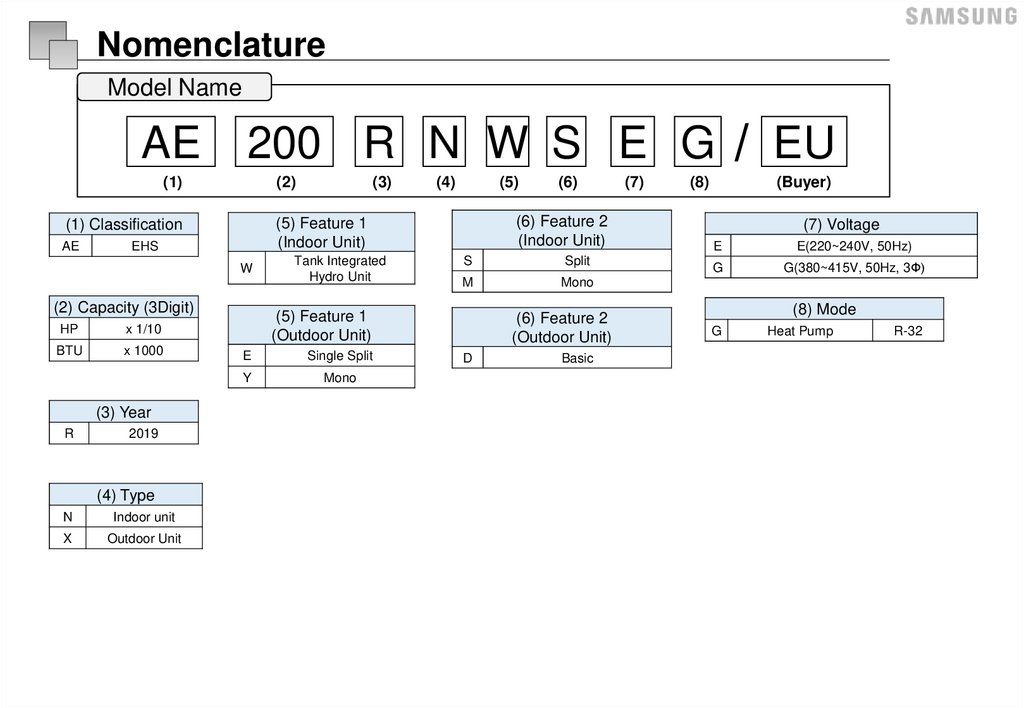
NomenclatureModel Name
AE
200 R N W S E G / EU
(1)
(2)
EHS
W
(2) Capacity (3Digit)
HP
x 1/10
BTU
x 1000
(3) Year
R
2019
(4) Type
N
Indoor unit
X
Outdoor Unit
(4)
(5)
Tank Integrated
Hydro Unit
S
Split
M
Mono
(5) Feature 1
(Outdoor Unit)
E
Single Split
Y
Mono
(6)
(6) Feature 2
(Indoor Unit)
(5) Feature 1
(Indoor Unit)
(1) Classification
AE
(3)
(6) Feature 2
(Outdoor Unit)
D
Basic
(7)
(8)
(Buyer)
(7) Voltage
E
E(220~240V, 50Hz)
G
G(380~415V, 50Hz, 3Ф)
(8) Mode
G
Heat Pump
R-32
10.
Preparation of installation■ Precautions
IMPORTANT: When installing the unit, always remember to connect first the refrigerant tubes, then the
electrical lines.Always disassemble the electric lines before the refrigerant tubes.
▶ Upon receipt, inspect the product to verify that it has not been damaged during transport.If the product
appears damaged, DO NOT INSTALL it and immediately report the damage to the carrier or retailer (if the
installer or the authorized technician has collected the material from the retailer.)
▶ After completing the installation, always carry out a functional test and provide the instructions on how to
operate the air to water heat pump to the user.
▶ Do not use the air to water heat pump in environments with hazardous substances or close to equipment
that release free flames to avoid the occurrence of fires, explosions or injuries.
▶ While in installation or relocation of the product, do not mix the refrigerant with other gases including air or
unspecified refrigerant.Failure to do so may cause pressure increase to result in rupture or injury.
▶ Do not cut or burn the refrigerant container or pipings.
▶ Use clean parts such as manifold gauge, vacuum pump, and charging hose for the refrigerant.
▶ Installation must be carried out by qualified personnel for handling the refrigerant.Additionally, reference the
regulations and laws.
▶ Be careful not to let foreign substances (lubricating oil, refrigerant other than R-32, water, etc.) enter the
pipings.
▶ When mechanical ventilation is required, ventilation openings shall be kept clear of obstruction.
▶ For disposal of the product, follow the local laws and regulations.
▶ Do not work in a confined place.
▶ The work area shall be blocked.
▶ The refrigerant pipings shall be installed in the position where there are no substances that may result in
corrosion.
▶ The following checks shall be performed for installation:
- The ventilation devices and outlets are operating normally and are not obstructed.
- Markings and signs on the equipment shall be visible and legible.
10/302
This Document can not be used without Samsung's authorization
11.
Preparation of installation■ Precautions
▶ Upon leakage of the refrigerant, ventilate the room.When the leaked refrigerant is exposed to flame, it may
cause generation of toxic gases.
▶ Make sure that the work area is safe from flammable substances.
▶ To purge air in the refrigerant, be sure to use a vacuum pump.
▶ Note that the refrigerant has no odour.
▶ The units are not explosion proof so they must be installed with no risk of explosion.
▶ This product contains fluorinated gases that contribute to global greenhouse effect.Accordingly, do not vent
gases into the atmosphere.
▶ For installation with handling the refrigerant(R-32), use dedicated tools and piping materials.
▶ Servicing and installation shall be performed as recommended by the manufacturer.In case other skilled
persons are joined for servicing, it shall be carried out under supervision of the person who is competent in
handling flammable refrigerants.
▶ For servicing the units containing flammable refrigerants, safety checks are required to minimise the risk of
ignition.
▶ Servicing shall be performed following the controlled procedure to minimize the risk of flammable refrigerant
or gases.
▶ Do not install where there is a risk of combustible gas leakage.
▶ Do not place heat sources.
▶ Be cautious not to generate a spark as follows: Do not remove the fuses with power on.
Do not disconnect the power plug from the wall outlet with power on.
It is recommended to locate the outlet in a high position.Place the cords so that they are not tangled.
▶ If the indoor unit is not R-32 compatible, an error signal appears and the unit will not operate.
▶ After installation, check for leakage.Toxic gas may be generated and if it comes into contact with an ignition
source such as fan heater, stove, and cooker.cylinders, make sure that only the refrigerant recovery cylinders
are used.
▶ Never directly touch any accidental leaking refrigerant.
▶ This could result in severe wounds caused by frostbite.
This Document can not be used without Samsung's authorization
11/302
12.
Preparation of installation■ Indoor unit / Outdoor unit compatibility
Indoor Unit
Tank integrated (Split)
Tank integrated (Mono)
Wall-mounted type
Mono
Power
Source
Type
1Φ
200L(1Φ)
Model Name
260L(1Φ)
260L(3Φ)
200L(1Φ)
260L(1Φ)
260L(3Φ)
Capa.
AE200RNWSEG AE260RNWSEG AE260RNWSGG AE200RNWMEG AE260RNWMEG
Split(1Φ)
Split(3Φ)
AE260RNWMG AE090RNYDEG AE090RNYDEG
G
(W43)
(W43)
MIM-E03CN
(W31)
AE040RXEDEG
4kW
AE060RXEDEG
6kW
AE090RXEDEG
9kW
AE090RXEDGG
9kW
AE050RXYDEG
5kW
AE080RXYDEG
8kW
AE120RXYDEG 12kW
AE160RXYDEG 16kW
Split
3Φ
Outdoor
unit
1Φ
Mono
AE080RXYDGG
3Φ
8kW
AE120RXYDGG 12kW
AE160RXYDGG 16kW
12/302
This Document can not be used without Samsung's authorization
13.
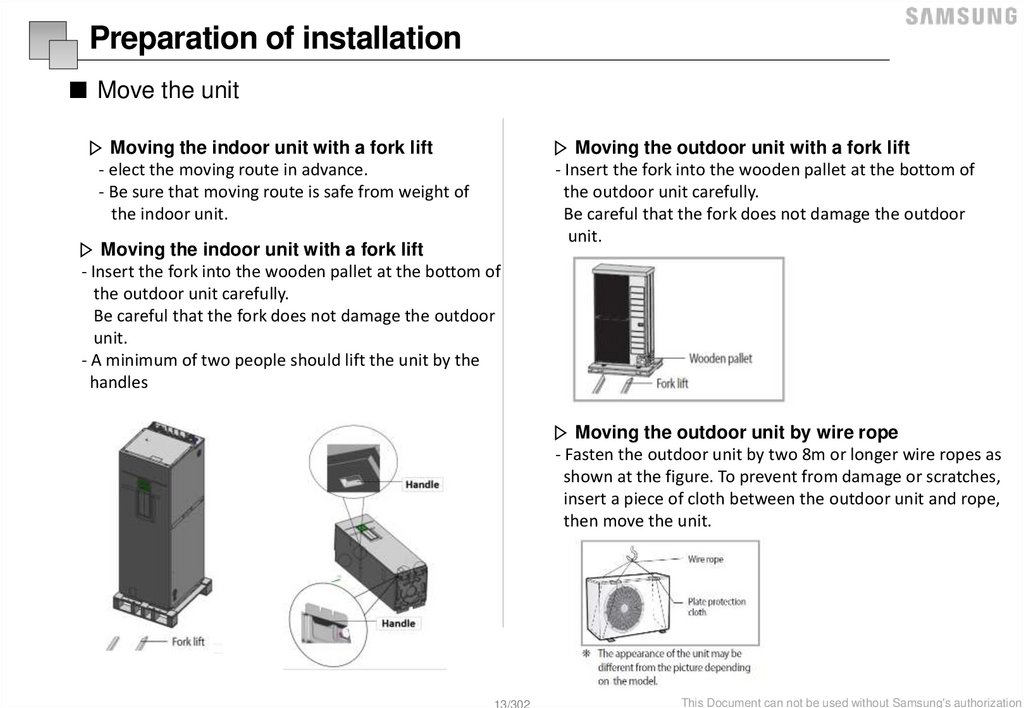
Preparation of installation■ Move the unit
▷ Moving the indoor unit with a fork lift
- elect the moving route in advance.
- Be sure that moving route is safe from weight of
the indoor unit.
▷ Moving the indoor unit with a fork lift
- Insert the fork into the wooden pallet at the bottom of
the outdoor unit carefully.
Be careful that the fork does not damage the outdoor
unit.
- A minimum of two people should lift the unit by the
handles
▷ Moving the outdoor unit with a fork lift
- Insert the fork into the wooden pallet at the bottom of
the outdoor unit carefully.
Be careful that the fork does not damage the outdoor
unit.
▷ Moving the outdoor unit by wire rope
- Fasten the outdoor unit by two 8m or longer wire ropes as
shown at the figure. To prevent from damage or scratches,
insert a piece of cloth between the outdoor unit and rope,
then move the unit.
13/302
This Document can not be used without Samsung's authorization
14.
MonoSplit
TDM
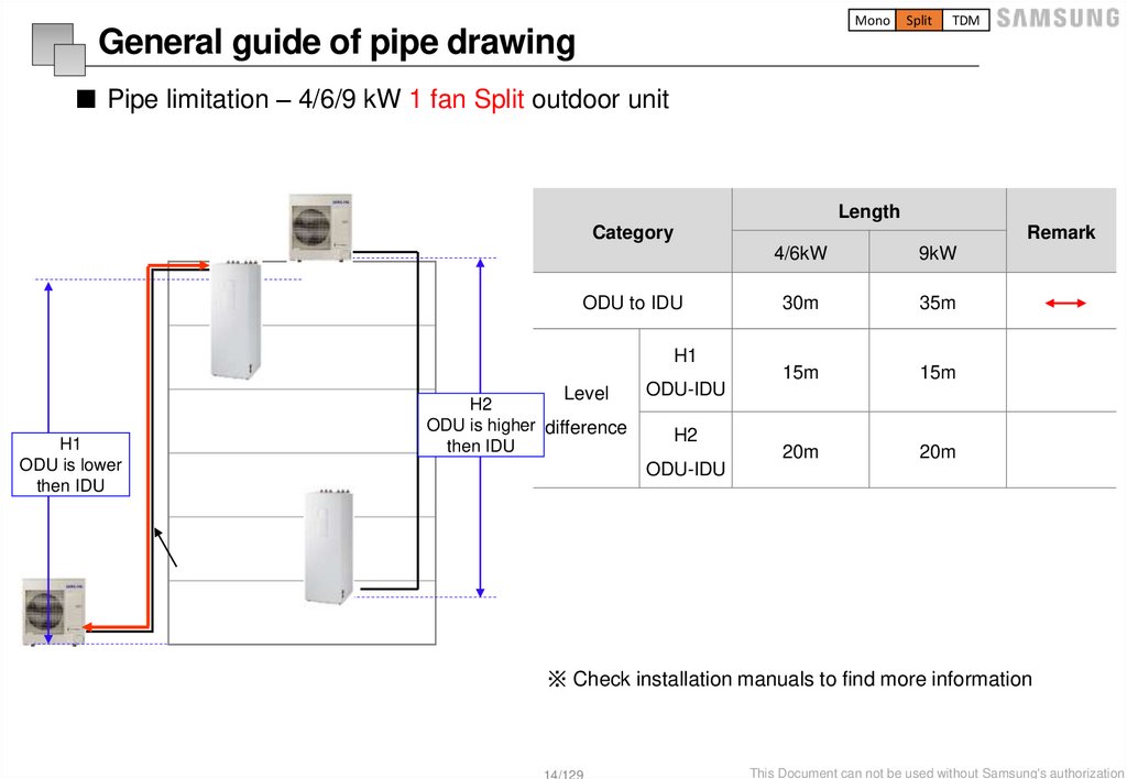
General guide of pipe drawing
■ Pipe limitation – 4/6/9 kW 1 fan Split outdoor unit
Length
Category
Remark
ODU to IDU
H1
Level
H1
ODU is lower
then IDU
H2
ODU is higher difference
then IDU
ODU-IDU
H2
ODU-IDU
4/6kW
9kW
30m
35m
15m
15m
20m
20m
※ Check installation manuals to find more information
14/129
This Document can not be used without Samsung's authorization
15.
MonoSplit
TDM
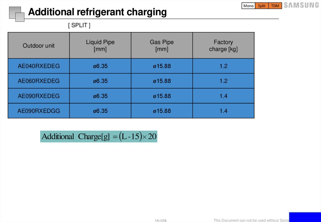
Additional refrigerant charging
[ SPLIT ]
Outdoor unit
Liquid Pipe
[mm]
Gas Pipe
[mm]
Factory
charge [kg]
AE040RXEDEG
ø6.35
ø15.88
1.2
AE060RXEDEG
ø6.35
ø15.88
1.2
AE090RXEDEG
ø6.35
ø15.88
1.4
AE090RXEDGG
ø6.35
ø15.88
1.4
Additional Charge[g] L -15 20
15/129
This Document can not be used without Samsung's authorization
16.
MonoSplit
TDM
Copper pipe
■ Copper pipe
ASTM standard copper pipe
Follow the minimum thickness & temper grade.
Otherwise pipe may be broken due to high pressure
Pipe size
mm(inch)
Φ 6.35(1/4”)
Φ 9.52(3/8”)
Φ12.70(1/2”)
Φ15.88(5/8”)
Minimum
thickness(mm)
0.7
0.7
0.8
1.0
Temper
grade
Annealed
type
C1220T-O
Use proper tool
De-burring tool
Tube cutter
* Brazing required to keep pipe more than 1 month on site
Cutting
- Use a tube Cutter
Burring
- Removing burr
Covering
- Block the end of pipe to prevent
foreign substance entering
Brazing
Taping
Cap
16/129
This Document can not be used without Samsung's authorization
17.
MonoSplit
TDM
Nitrogen gas blowing
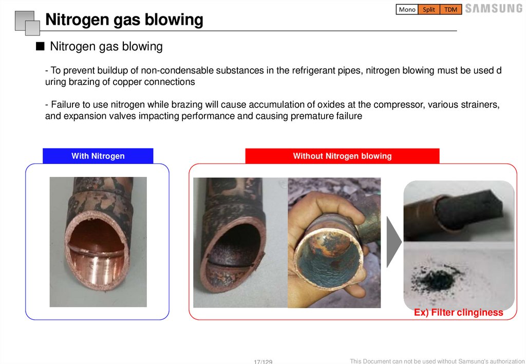
■ Nitrogen gas blowing
- To prevent buildup of non-condensable substances in the refrigerant pipes, nitrogen blowing must be used d
uring brazing of copper connections
- Failure to use nitrogen while brazing will cause accumulation of oxides at the compressor, various strainers,
and expansion valves impacting performance and causing premature failure
With Nitrogen
Without Nitrogen blowing
Ex) Filter clinginess
17/129
This Document can not be used without Samsung's authorization
18.
MonoSplit
TDM
Nitrogen gas blowing
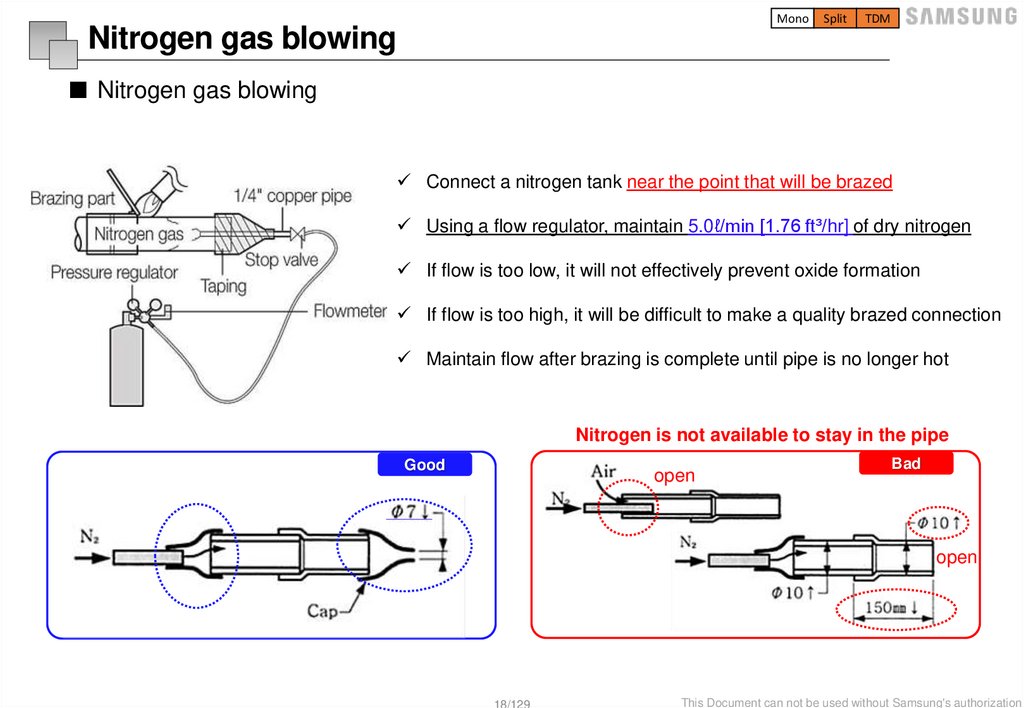
■ Nitrogen gas blowing
Connect a nitrogen tank near the point that will be brazed
Using a flow regulator, maintain 5.0ℓ/min [1.76 ft³/hr] of dry nitrogen
If flow is too low, it will not effectively prevent oxide formation
If flow is too high, it will be difficult to make a quality brazed connection
Maintain flow after brazing is complete until pipe is no longer hot
Nitrogen is not available to stay in the pipe
Good
open
Bad
open
18/129
This Document can not be used without Samsung's authorization
19.
MonoSplit
TDM
Brazing
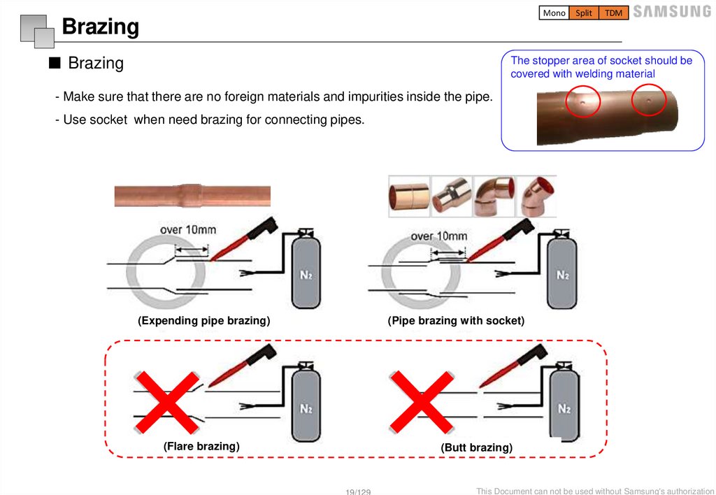
■ Brazing
The stopper area of socket should be
covered with welding material
- Make sure that there are no foreign materials and impurities inside the pipe.
- Use socket when need brazing for connecting pipes.
(Expending pipe brazing)
(Pipe brazing with socket)
(Flare brazing)
(Butt brazing)
19/129
This Document can not be used without Samsung's authorization
20.
MonoSplit
TDM
Mounting
■ Mounting
1) Installing the hanger bolt(or others like ladder tray )
- Φ12.7 or less : 1.5m or less
- Φ15.88 or more : 2m or less
* If the distance is longer, pipe might be sagged by its weight
2) Insulating the pipe (Refer to Insulation work)
- Keep the tape or cap end of each side
3) Hanging the pipe
- Insert Insulation pad between pipe & hanger to prevent
insulation being pressed
a
20/129
This Document can not be used without Samsung's authorization
21.
MonoSplit
TDM
Airtight Test
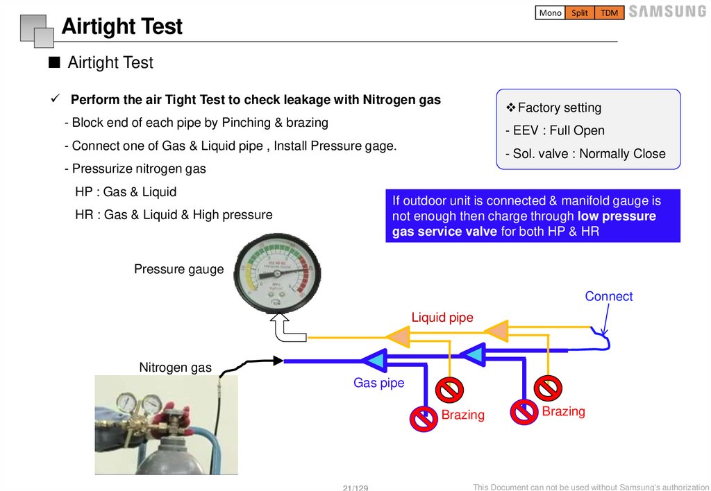
■ Airtight Test
Perform the air Tight Test to check leakage with Nitrogen gas
Factory setting
- Block end of each pipe by Pinching & brazing
- EEV : Full Open
- Connect one of Gas & Liquid pipe , Install Pressure gage.
- Sol. valve : Normally Close
- Pressurize nitrogen gas
HP : Gas & Liquid
If outdoor unit is connected & manifold gauge is
not enough then charge through low pressure
gas service valve for both HP & HR
HR : Gas & Liquid & High pressure
Pressure gauge
Connect
Liquid pipe
Nitrogen gas
Gas pipe
Brazing
21/129
Brazing
This Document can not be used without Samsung's authorization
22.
MonoSplit
TDM
Airtight Test
■ Airtight Test
※ Test Pressure
- R-32 : 46.9kgf/cm2 = 4.6Mpa = 667.2psi
Nitrogen pressurization
1. Maintains 4.6MPa for 24 hours. If no leakage, then pressure down to 1MPa.
2. If there is pressure drop then find leak point and
3. Maintain 1MPa(145psi) until connecting the outdoor/indoor units to prevent corrosion in the copper pipes.
Maintain a pressure of 4.1MPa
Mark on the gage(wait for 24hours)
22/129
Maintain a pressure of 1.0MPa
This Document can not be used without Samsung's authorization
23.
MonoSplit
TDM
Insulation
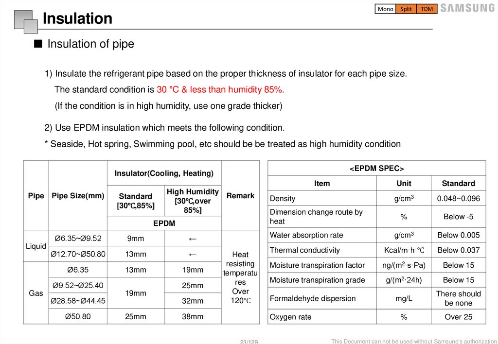
■ Insulation of pipe
1) Insulate the refrigerant pipe based on the proper thickness of insulator for each pipe size.
The standard condition is 30 °C & less than humidity 85%.
(If the condition is in high humidity, use one grade thicker)
2) Use EPDM insulation which meets the following condition.
* Seaside, Hot spring, Swimming pool, etc should be be treated as high humidity condition
<EPDM SPEC>
Insulator(Cooling, Heating)
Item
Pipe Pipe Size(mm)
Standard
[30℃,85%]
High Humidity
Remark
[30℃,over
85%]
EPDM
Liquid
Ø6.35~Ø9.52
9mm
←
Ø12.70~Ø50.80
13mm
←
Ø6.35
13mm
19mm
Ø9.52~Ø25.40
Gas
Ø28.58~Ø44.45
Ø50.80
25mm
19mm
32mm
25mm
Heat
resisting
temperatu
res
Over
120℃
38mm
23/129
Unit
Standard
g/cm3
0.048~0.096
%
Below -5
Water absorption rate
g/cm3
Below 0.005
Thermal conductivity
Kcal/m·h·℃
Below 0.037
Moisture transpiration factor
ng/(m2·s·Pa)
Below 15
Moisture transpiration grade
g/(m2·24h)
Below 15
Formaldehyde dispersion
mg/L
There should
be none
Oxygen rate
%
Over 25
Density
Dimension change route by
heat
This Document can not be used without Samsung's authorization
24.
MonoSplit
TDM
Insulation
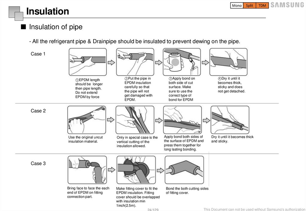
■ Insulation of pipe
- All the refrigerant pipe & Drainpipe should be insulated to prevent dewing on the pipe.
Case 1
②Put the pipe in
EPDM insulation
carefully so that
the pipe will not
get damaged with
EPDM.
③Apply bond on
both side of cut
surface. Make
sure to use the
correct type of
bond for EPDM
④Dry it until it
becomes thick,
sticky and does
not get detached.
Use the original uncut
insulation material.
Only in special case is the
vertical cutting of the
insulation allowed.
Apply bond both sides of
the surface of EPDM and
press them together for
long lasting bonding.
Dry it until it becomes thick
and sticky.
Bring face to face the each
end of EPDM on fitting
connection part.
Make fitting cover to fit the
EPDM insulation. Fitting
cover should be overlapped
with insulation min
1inch(2.5m).
24/129
Bond the both cutting sides
of fitting cover.
①EPDM length
should be longer
then pipe length.
Do not extend
EPDM by force
Case 2
Case 3
This Document can not be used without Samsung's authorization
25.
MonoSplit
TDM
Insulation
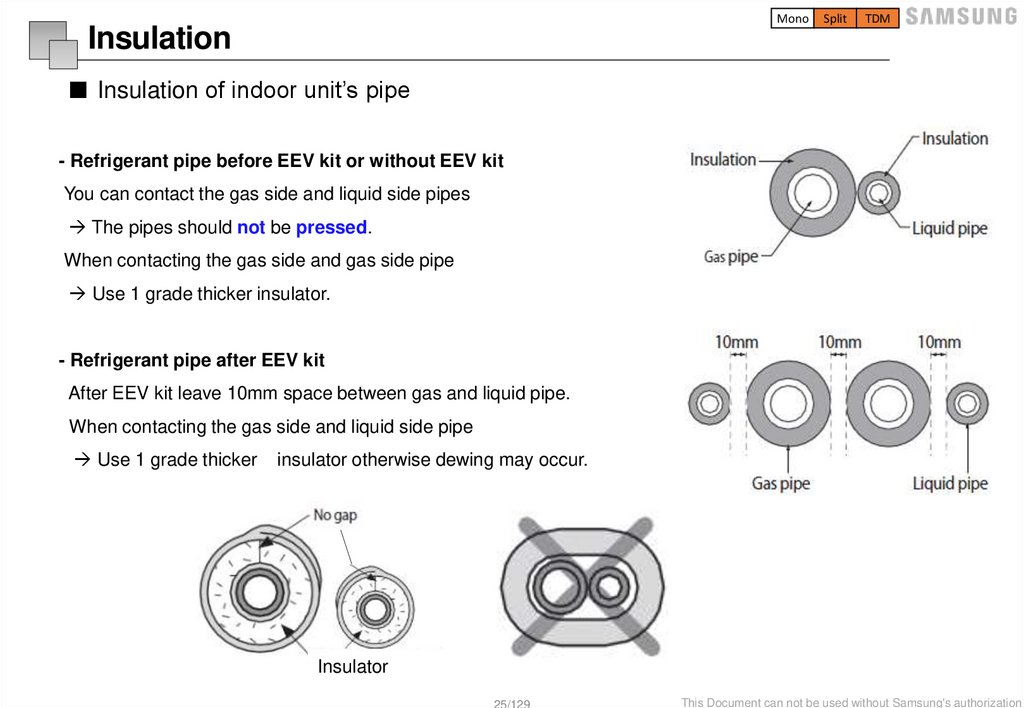
■ Insulation of indoor unit’s pipe
- Refrigerant pipe before EEV kit or without EEV kit
You can contact the gas side and liquid side pipes
The pipes should not be pressed.
When contacting the gas side and gas side pipe
Use 1 grade thicker insulator.
- Refrigerant pipe after EEV kit
After EEV kit leave 10mm space between gas and liquid pipe.
When contacting the gas side and liquid side pipe
Use 1 grade thicker
insulator otherwise dewing may occur.
Insulator
25/129
This Document can not be used without Samsung's authorization
26.
MonoSplit
TDM
Selection of wire and circuit breaker
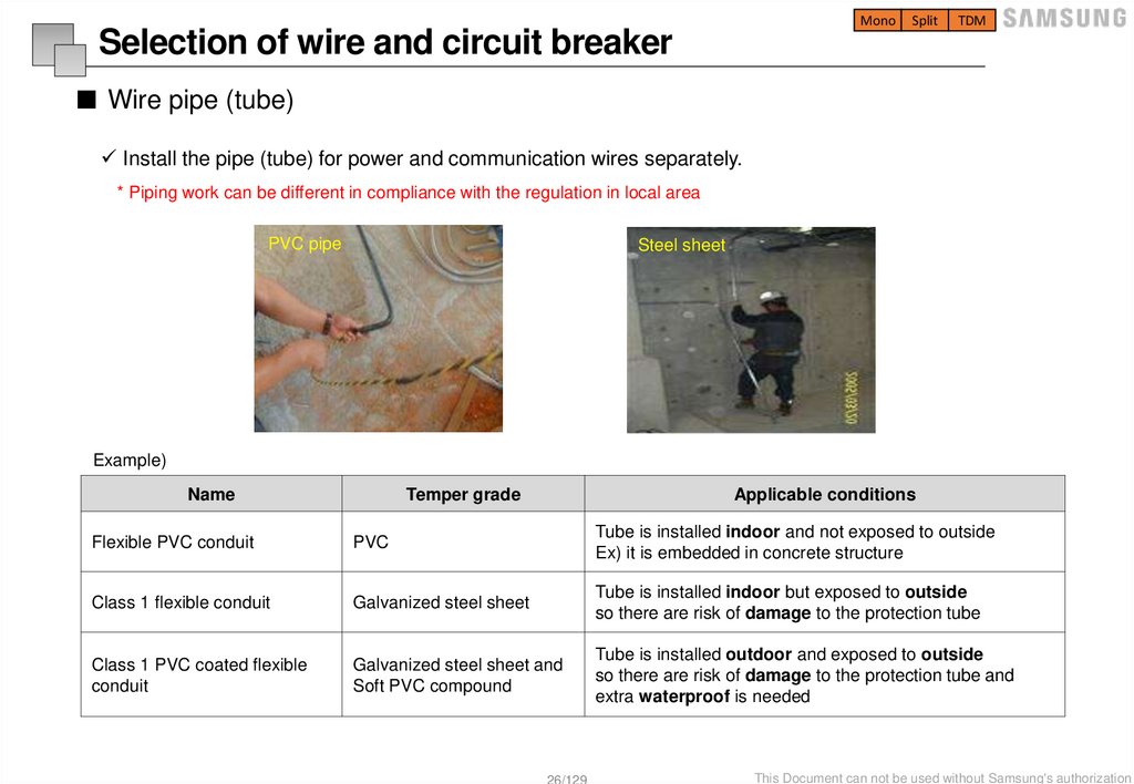
■ Wire pipe (tube)
Install the pipe (tube) for power and communication wires separately.
* Piping work can be different in compliance with the regulation in local area
PVC pipe
Steel sheet
Example)
Name
Temper grade
Applicable conditions
Flexible PVC conduit
PVC
Tube is installed indoor and not exposed to outside
Ex) it is embedded in concrete structure
Class 1 flexible conduit
Galvanized steel sheet
Tube is installed indoor but exposed to outside
so there are risk of damage to the protection tube
Class 1 PVC coated flexible
conduit
Galvanized steel sheet and
Soft PVC compound
Tube is installed outdoor and exposed to outside
so there are risk of damage to the protection tube and
extra waterproof is needed
26/129
This Document can not be used without Samsung's authorization
27.
MonoSplit
TDM
Selection of wire and circuit breaker
■ Solderless ring terminal
- Select a solderless ring terminal for a power cable according to the nominal dimensions of cable.
- Apply insulation coating to the connection part of the solderless ring terminal and the power cable.
Power terminal
* Do not use Y-shape for power cable.
Communication
terminal
27/129
This Document can not be used without Samsung's authorization
28.
MonoSplit
TDM
Selection of wire and circuit breaker
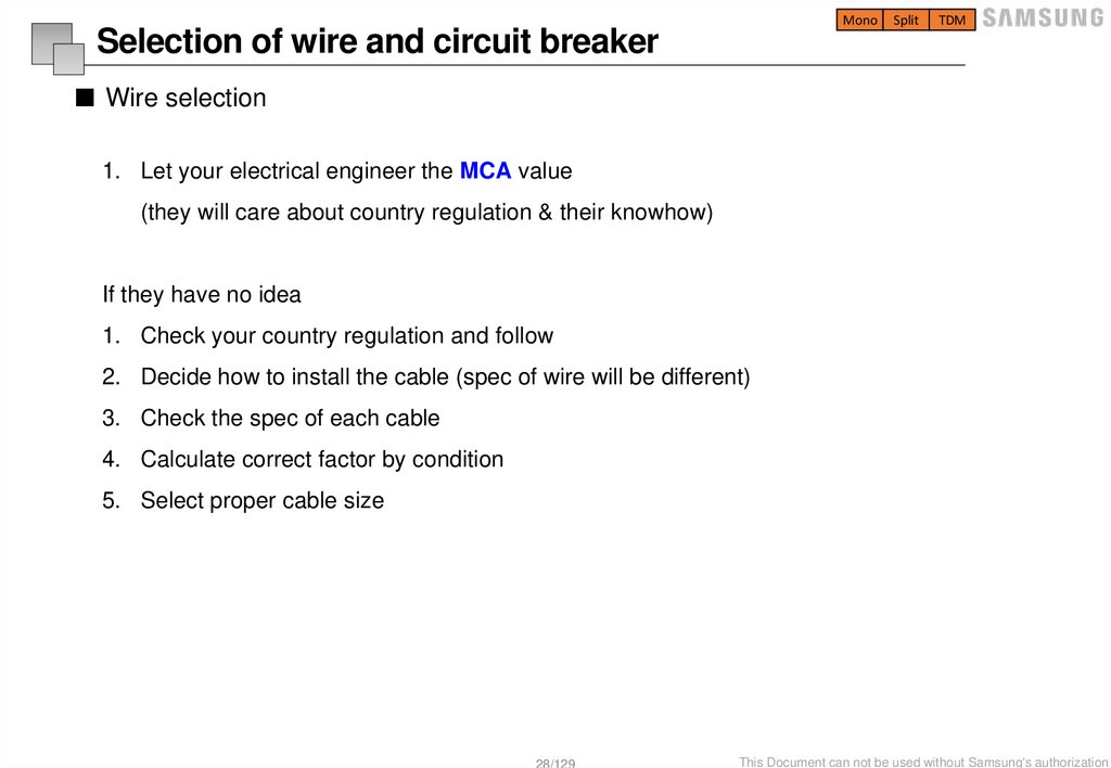
■ Wire selection
1. Let your electrical engineer the MCA value
(they will care about country regulation & their knowhow)
If they have no idea
1. Check your country regulation and follow
2. Decide how to install the cable (spec of wire will be different)
3. Check the spec of each cable
4. Calculate correct factor by condition
5. Select proper cable size
28/129
This Document can not be used without Samsung's authorization
29.
MonoSplit
TDM
Installation tip
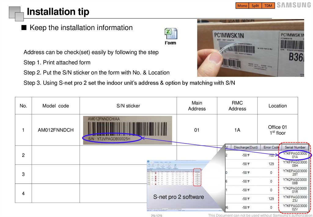
■ Keep the installation information
Address can be check(set) easily by following the step
Step 1. Print attached form
Step 2. Put the S/N sticker on the form with No. & Location
Step 3. Using S-net pro 2 set the indoor unit’s address & option by matching with S/N
No.
Model code
1
AM012FNNDCH
S/N sticker
Main
Address
RMC
Address
Location
01
1A
Office 01
1st floor
2
3
4
S-net pro 2 software
29/129
This Document can not be used without Samsung's authorization
30.
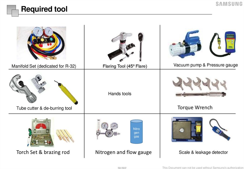
Required toolManifold Set (dedicated for R-32)
Flaring Tool (45º Flare)
Vacuum pump & Pressure gauge
Hands tools
Torque Wrench
Tube cutter & de-burring tool
Nitro
gen
gas
Torch Set & brazing rod
Nitrogen and flow gauge
Scale & leakage detector
30/302
This Document can not be used without Samsung's authorization
31.
Tank intergrated Hydro unit32.
MonoSplit
TDM
Example of application
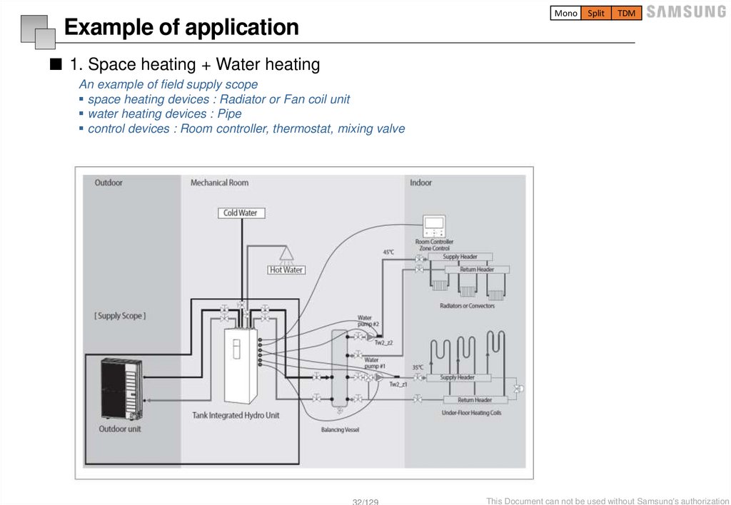
■ 1. Space heating + Water heating
An example of field supply scope
space heating devices : Radiator or Fan coil unit
water heating devices : Pipe
control devices : Room controller, thermostat, mixing valve
32/129
This Document can not be used without Samsung's authorization
33.
MonoSplit
TDM
Example of application
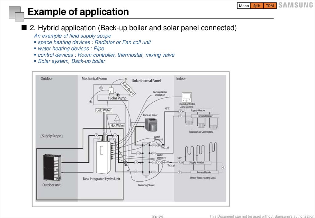
■ 2. Hybrid application (Back-up boiler and solar panel connected)
An example of field supply scope
space heating devices : Radiator or Fan coil unit
water heating devices : Pipe
control devices : Room controller, thermostat, mixing valve
Solar system, Back-up boiler
33/129
This Document can not be used without Samsung's authorization
34.
MonoSplit
Installation information
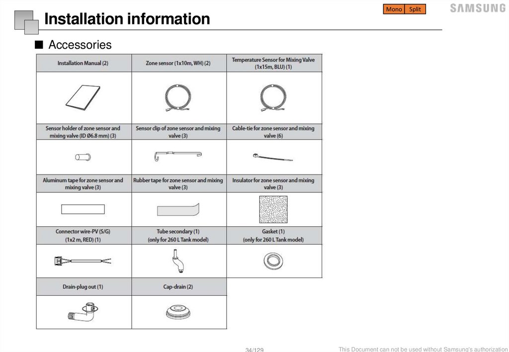
■ Accessories
34/129
This Document can not be used without Samsung's authorization
35.
MonoSplit
Main components
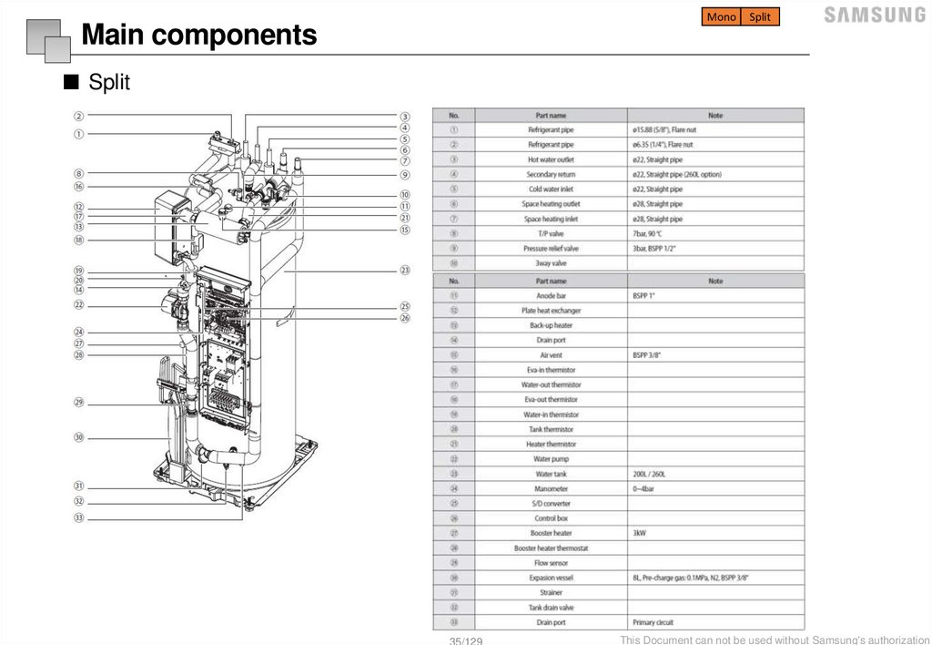
■ Split
35/129
This Document can not be used without Samsung's authorization
36.
MonoSplit
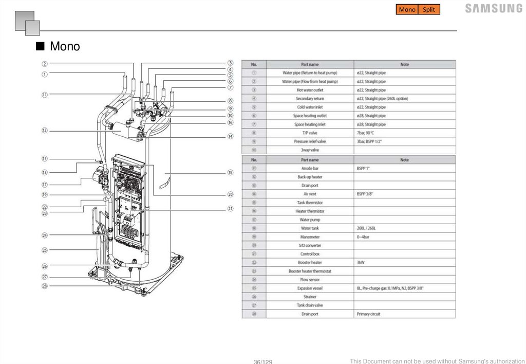
■ Mono
36/129
This Document can not be used without Samsung's authorization
37.
MonoSplit
Installation information
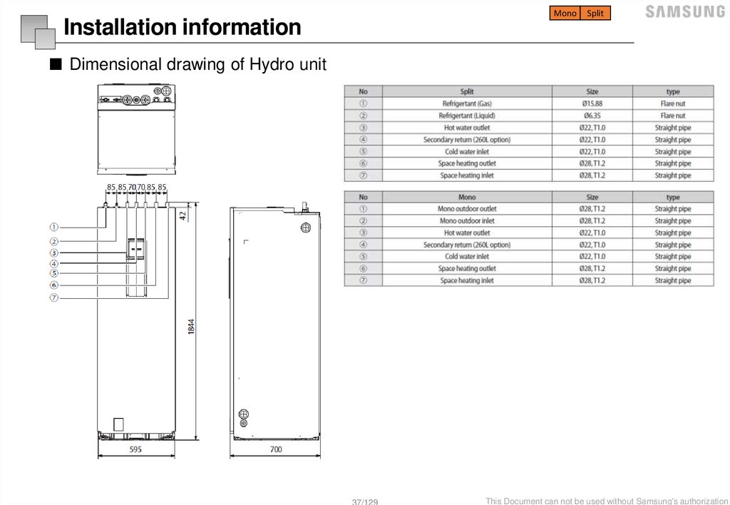
■ Dimensional drawing of Hydro unit
37/129
This Document can not be used without Samsung's authorization
38.
MonoSplit
Installation information
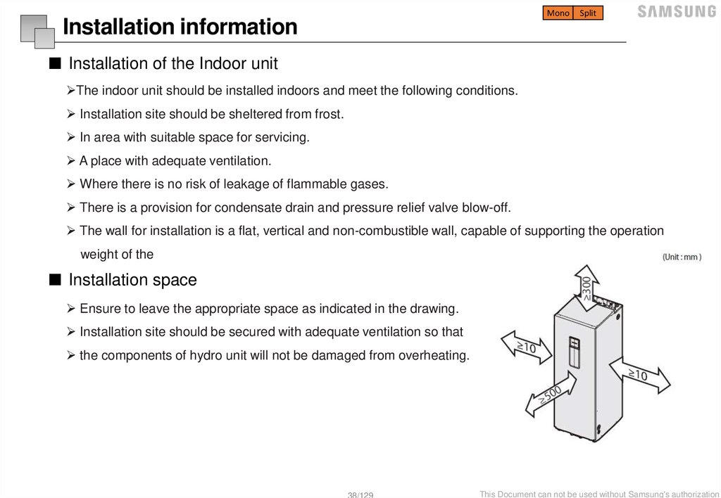
■ Installation of the Indoor unit
The indoor unit should be installed indoors and meet the following conditions.
Installation site should be sheltered from frost.
In area with suitable space for servicing.
A place with adequate ventilation.
Where there is no risk of leakage of flammable gases.
There is a provision for condensate drain and pressure relief valve blow-off.
The wall for installation is a flat, vertical and non-combustible wall, capable of supporting the operation
weight of the
■ Installation space
Ensure to leave the appropriate space as indicated in the drawing.
Installation site should be secured with adequate ventilation so that
the components of hydro unit will not be damaged from overheating.
38/129
This Document can not be used without Samsung's authorization
39.
Installation information기구작업
추가수정 필요
Mono
Split
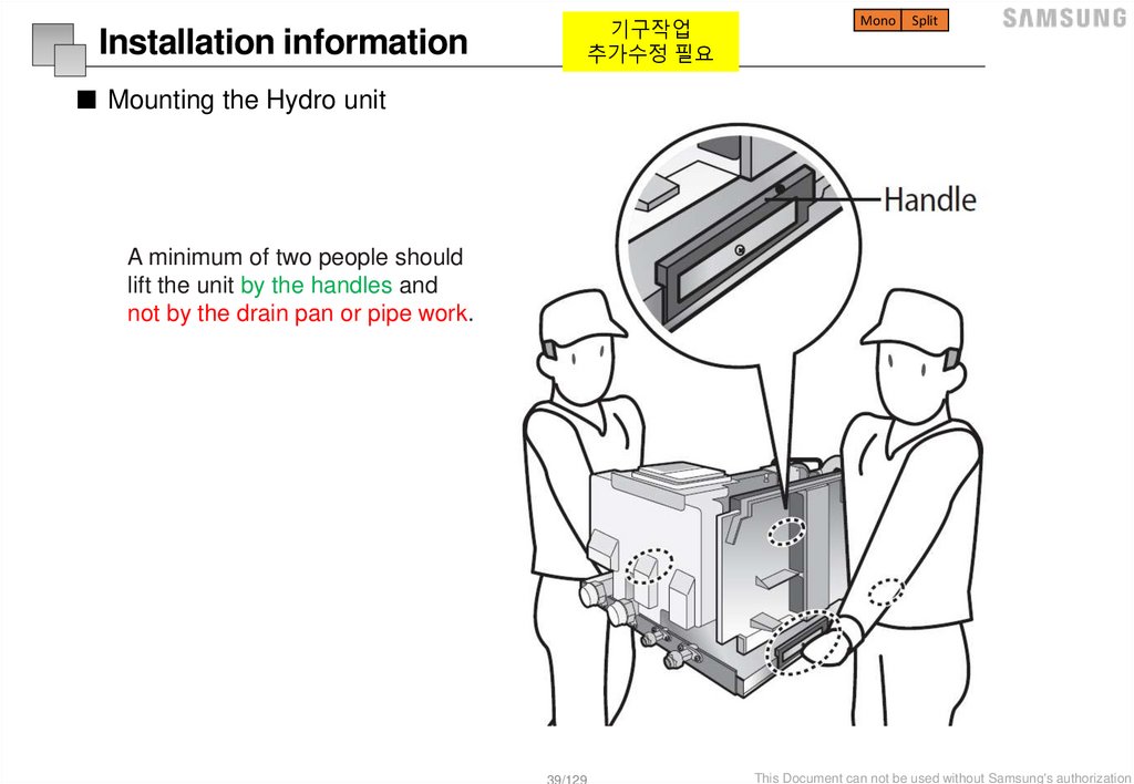
■ Mounting the Hydro unit
A minimum of two people should
lift the unit by the handles and
not by the drain pan or pipe work.
39/129
This Document can not be used without Samsung's authorization
40.
MonoSplit
Installation information
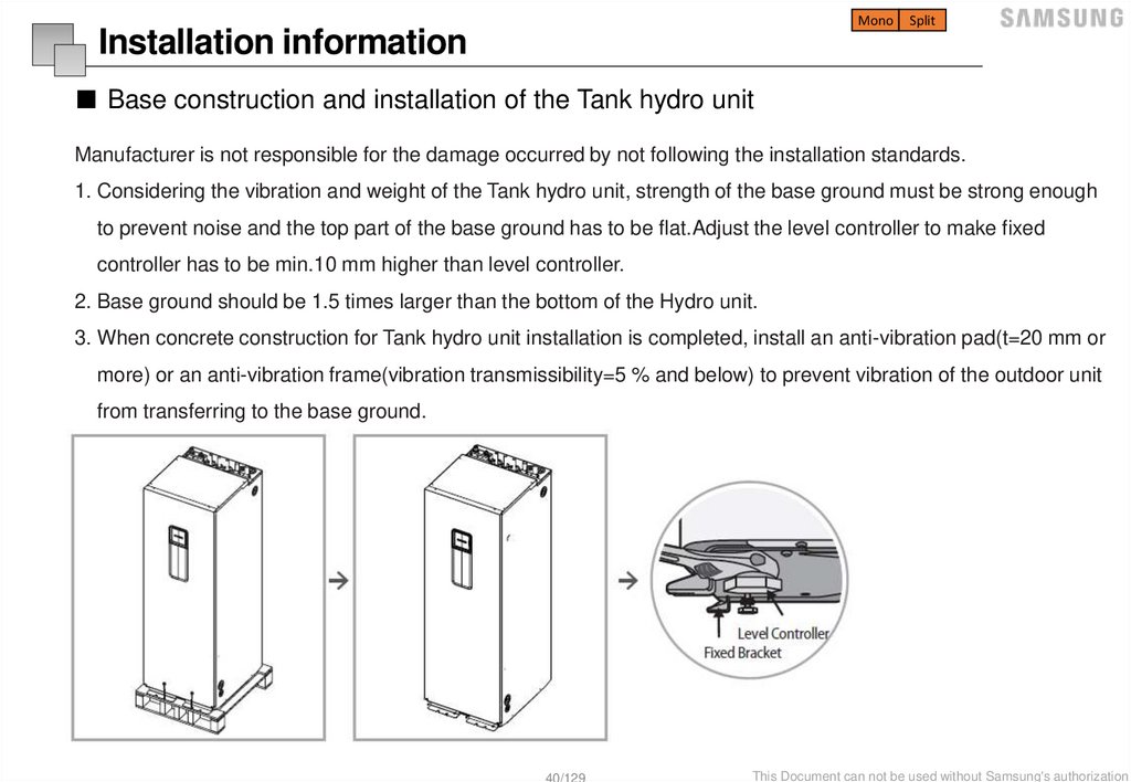
■ Base construction and installation of the Tank hydro unit
Manufacturer is not responsible for the damage occurred by not following the installation standards.
1. Considering the vibration and weight of the Tank hydro unit, strength of the base ground must be strong enough
to prevent noise and the top part of the base ground has to be flat.Adjust the level controller to make fixed
controller has to be min.10 mm higher than level controller.
2. Base ground should be 1.5 times larger than the bottom of the Hydro unit.
3. When concrete construction for Tank hydro unit installation is completed, install an anti-vibration pad(t=20 mm or
more) or an anti-vibration frame(vibration transmissibility=5 % and below) to prevent vibration of the outdoor unit
from transferring to the base ground.
40/129
This Document can not be used without Samsung's authorization
41.
MonoSplit
Installation information
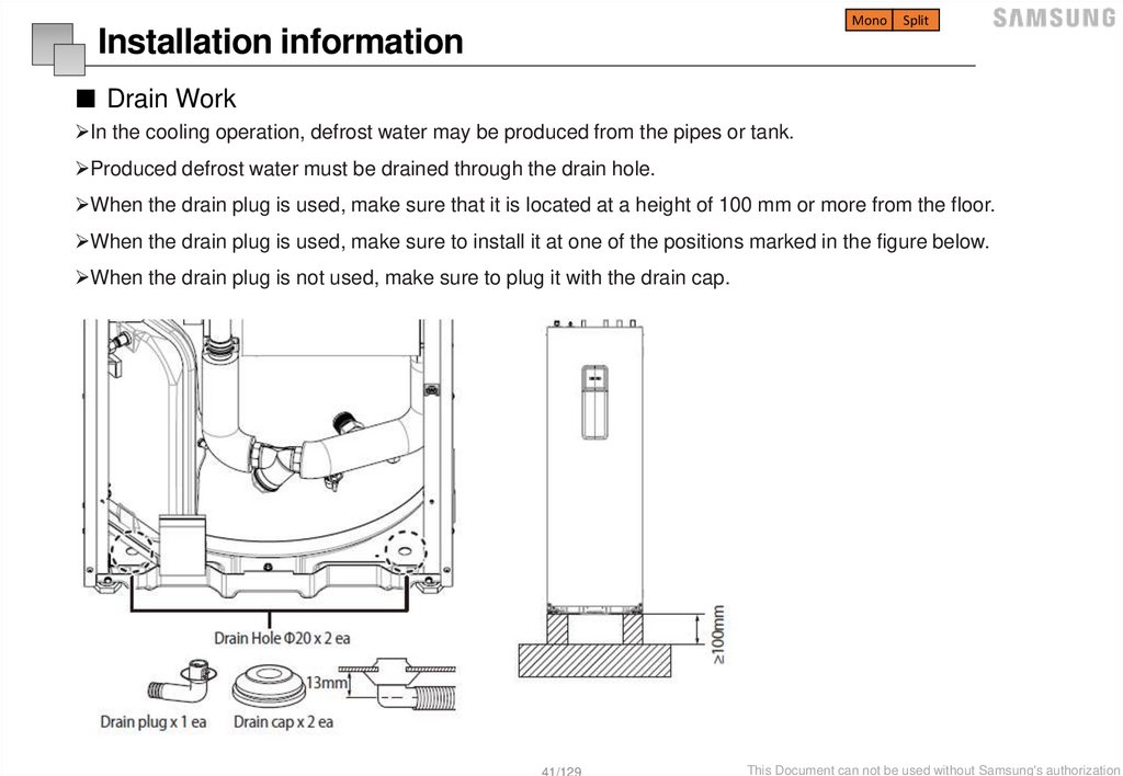
■ Drain Work
In the cooling operation, defrost water may be produced from the pipes or tank.
Produced defrost water must be drained through the drain hole.
When the drain plug is used, make sure that it is located at a height of 100 mm or more from the floor.
When the drain plug is used, make sure to install it at one of the positions marked in the figure below.
When the drain plug is not used, make sure to plug it with the drain cap.
41/129
This Document can not be used without Samsung's authorization
42.
MonoSplit
Charging a water into the system
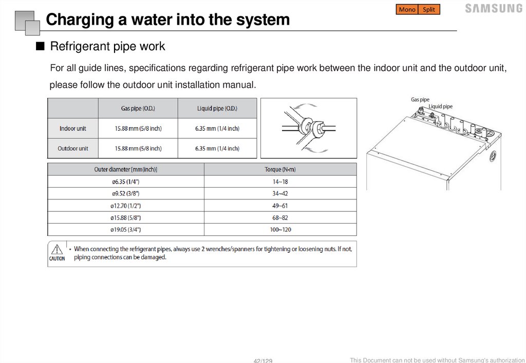
■ Refrigerant pipe work
For all guide lines, specifications regarding refrigerant pipe work between the indoor unit and the outdoor unit,
please follow the outdoor unit installation manual.
42/129
This Document can not be used without Samsung's authorization
43.
MonoSplit
Charging a water into the system
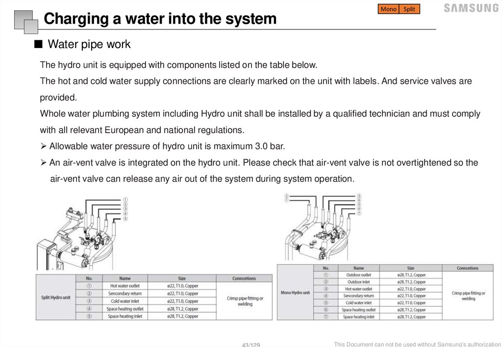
■ Water pipe work
The hydro unit is equipped with components listed on the table below.
The hot and cold water supply connections are clearly marked on the unit with labels. And service valves are
provided.
Whole water plumbing system including Hydro unit shall be installed by a qualified technician and must comply
with all relevant European and national regulations.
Allowable water pressure of hydro unit is maximum 3.0 bar.
An air-vent valve is integrated on the hydro unit. Please check that air-vent valve is not overtightened so the
air-vent valve can release any air out of the system during system operation.
43/129
This Document can not be used without Samsung's authorization
44.
MonoSplit
Charging a water into the system
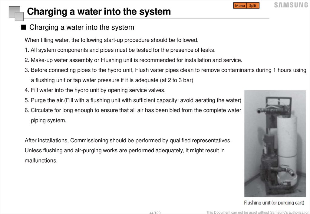
■ Charging a water into the system
When filling water, the following start-up procedure should be followed.
1. All system components and pipes must be tested for the presence of leaks.
2. Make-up water assembly or Flushing unit is recommended for installation and service.
3. Before connecting pipes to the hydro unit, Flush water pipes clean to remove contaminants during 1 hours using
a flushing unit or tap water pressure if it is adequate (at 2 to 3 bar)
4. Fill water into the hydro unit by opening service valves.
5. Purge the air.(Fill with a flushing unit with sufficient capacity: avoid aerating the water)
6. Circulate for long enough to ensure that all air has been bled from the complete water
piping system.
After installations, Commissioning should be performed by qualified representatives.
Unless flushing and air-purging works are performed adequately, It might result in
malfunctions.
44/129
This Document can not be used without Samsung's authorization
45.
MonoSplit
Charging a water into the system
■ Charging a water into the system (Caution !!)
Check and clean strainer periodically.
Replace strainer when necessary.
Its recommended that you flush the system for 4 hours minimum once a per annum.
Use chemical cleaning agents(Begin with acid , finish with alkali).
Install Air vents on the top of the system
The complete water circuit, including all pipe must be insulated to prevent condensation forming on the surface of the pipe and
heat loss to external environment.
45/129
This Document can not be used without Samsung's authorization
46.
MonoSplit
Charging a water into the system
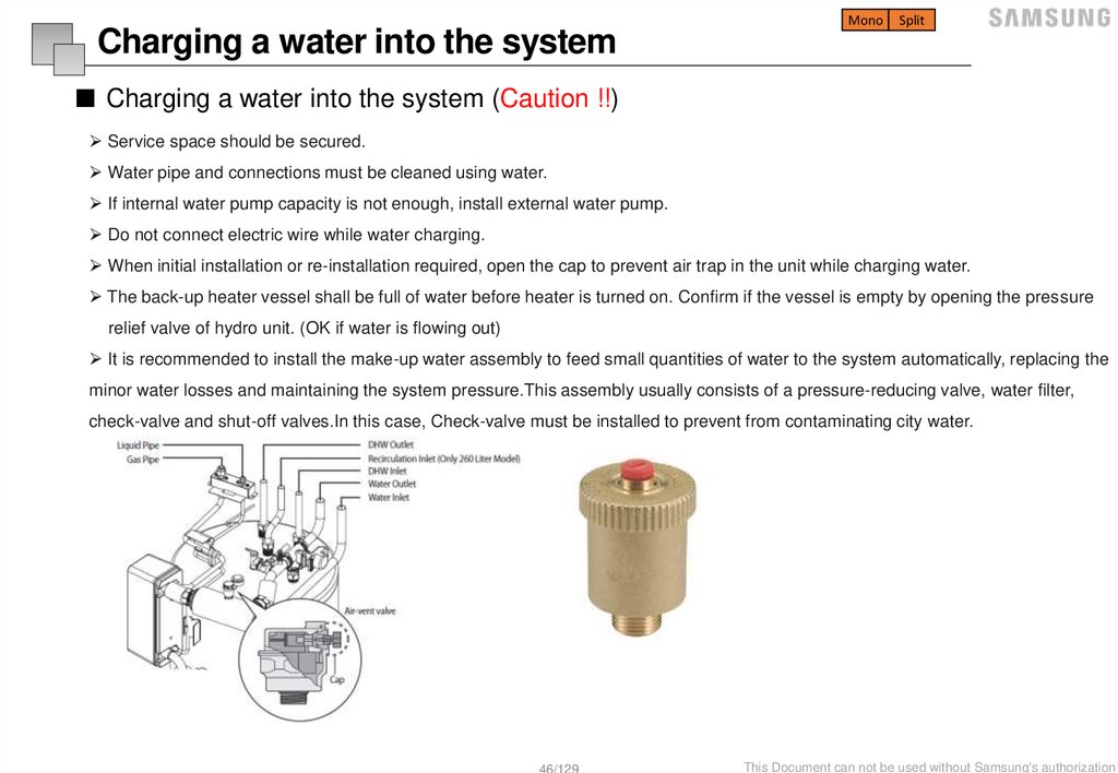
■ Charging a water into the system (Caution !!)
Service space should be secured.
Water pipe and connections must be cleaned using water.
If internal water pump capacity is not enough, install external water pump.
Do not connect electric wire while water charging.
When initial installation or re-installation required, open the cap to prevent air trap in the unit while charging water.
The back-up heater vessel shall be full of water before heater is turned on. Confirm if the vessel is empty by opening the pressure
relief valve of hydro unit. (OK if water is flowing out)
It is recommended to install the make-up water assembly to feed small quantities of water to the system automatically, replacing the
minor water losses and maintaining the system pressure.This assembly usually consists of a pressure-reducing valve, water filter,
check-valve and shut-off valves.In this case, Check-valve must be installed to prevent from contaminating city water.
46/129
This Document can not be used without Samsung's authorization
47.
MonoSplit
TDM
Charging a water into the system
■ How to choose an expansion vessel
When it is required to change the default pre-pressure of the expansion vessel(1 bar), keep in mind the following guidelines:
Use only dry nitrogen to set the expansion vessel pre-pressure.
Improper setting of the expansion vessel pre-pressure will make malfunction of the system.
Therefore, the pre-pressure should be adjusted by a licensed installer.
Installation
Height
Difference
Water Volume
< 220 Litres
No pre-pressure adjustment
required
<7m
> 220 Litres
Actions required:
Pre-pressure must be decreased,
calculate according
To “Calculating the pre-pressure
of the expansion vessel”.
Check if the water volume is
lower than maximum allowed
Water volume
Minimum!
>7 m
H
Pg ( 0.3)
10
Pg:
Pre-Pressure [bar]
H:
Maximum installation height difference
Actions required:
Pre-pressure must be
Expansion vessel of the unit too
increased, calculate the
Small for the installation.
appropriate value following
by “Calculating the pre-pressure
of the expansion vessel”.
Check if the water volume is
lower than maximum allowed
water volume
47/129
This Document can not be used without Samsung's authorization
48.
MonoSplit
TDM
Charging a water into the system
■ How to choose a water pump
The illustration below shows the external static pressure of the unit depending on the water flow and the pump setting.
When ESP is not enough, additional pump should be installed. In this case, install the PWM control external type pump
(Heating type) additionally.
The additional pump should be the same
type of product as graph.
If there is wrong wiring, the pump will not
work properly.
ALL Model : GRUNDFOS UPMM 25-9.5 (Heating Type)
48/129
This Document can not be used without Samsung's authorization
49.
MonoSplit
TDM
Charging a water into the system
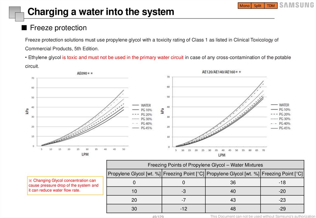
■ Freeze protection
Freeze protection solutions must use propylene glycol with a toxicity rating of Class 1 as listed in Clinical Toxicology of
Commercial Products, 5th Edition.
• Ethylene glycol is toxic and must not be used in the primary water circuit in case of any cross-contamination of the potable
circuit.
Freezing Points of Propylene Glycol – Water Mixtures
Propylene Glycol [wt. %] Freezing Point [°C] Propylene Glycol [wt. %] Freezing Point [°C]
※ Changing Glycol concentration can
cause pressure drop of the system and
it can reduce water flow rate.
0
0
36
-18
10
-3
40
-20
20
-7
43
-23
30
-12
48
-29
49/129
This Document can not be used without Samsung's authorization
50.
Split outdoor unit51.
MonoSplit
TDM
Installation information
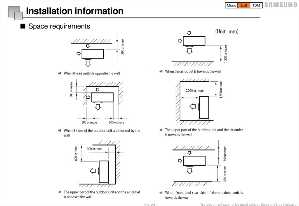
■ Space requirements
51/129
This Document can not be used without Samsung's authorization
52.
MonoSplit
TDM
Installation information
■ Base and anchor bolts
AE040/050/060RX**EG
AE080/090/120/160RXYD*G
52/129
This Document can not be used without Samsung's authorization
53.
MonoSplit
TDM
Installation information
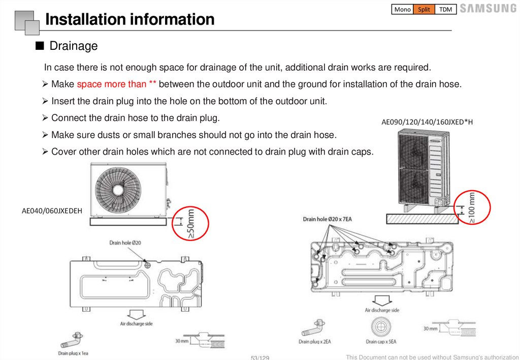
■ Drainage
In case there is not enough space for drainage of the unit, additional drain works are required.
Make space more than ** between the outdoor unit and the ground for installation of the drain hose.
Insert the drain plug into the hole on the bottom of the outdoor unit.
Connect the drain hose to the drain plug.
AE090/120/140/160JXED*H
Make sure dusts or small branches should not go into the drain hose.
Cover other drain holes which are not connected to drain plug with drain caps.
AE040/060JXEDEH
53/129
This Document can not be used without Samsung's authorization
54.
MonoSplit
TDM
Wiring
Rated
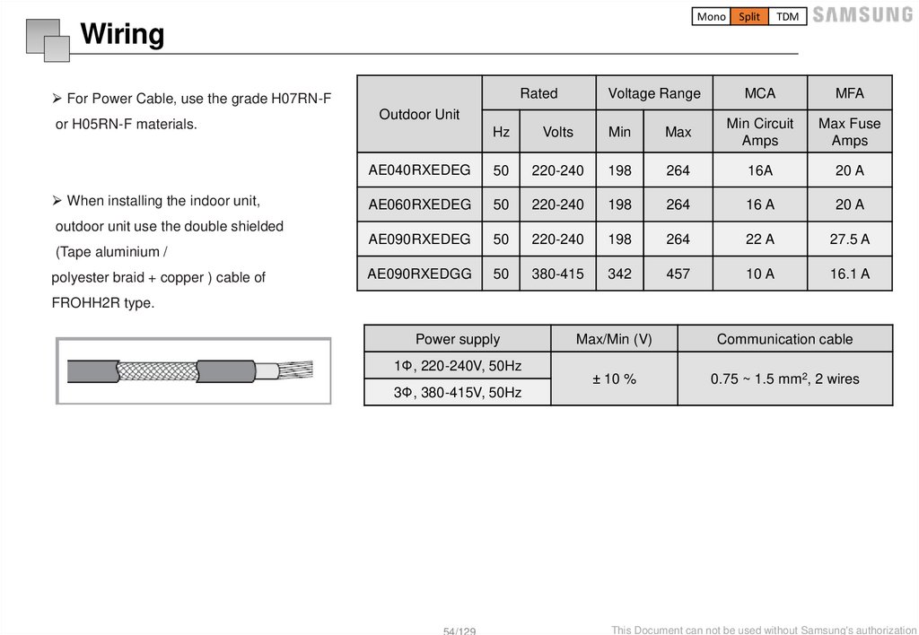
For Power Cable, use the grade H07RN-F
or H05RN-F materials.
When installing the indoor unit,
outdoor unit use the double shielded
(Tape aluminium /
polyester braid + copper ) cable of
Voltage Range
Outdoor Unit
MCA
MFA
Hz
Volts
Min
Max
Min Circuit
Amps
Max Fuse
Amps
AE040RXEDEG
50
220-240
198
264
16A
20 A
AE060RXEDEG
50
220-240
198
264
16 A
20 A
AE090RXEDEG
50
220-240
198
264
22 A
27.5 A
AE090RXEDGG
50
380-415
342
457
10 A
16.1 A
FROHH2R type.
Power supply
1Φ, 220-240V, 50Hz
Max/Min (V)
Communication cable
± 10 %
0.75 ~ 1.5 mm2, 2 wires
3Φ, 380-415V, 50Hz
54/129
This Document can not be used without Samsung's authorization
55.
Mono outdoor unit56.
MonoSplit
TDM
Installation information
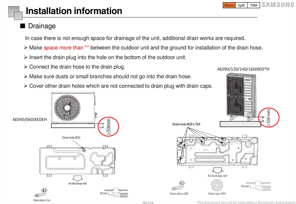
■ Drainage
In case there is not enough space for drainage of the unit, additional drain works are required.
Make space more than ** between the outdoor unit and the ground for installation of the drain hose.
Insert the drain plug into the hole on the bottom of the outdoor unit.
Connect the drain hose to the drain plug.
AE090/120/140/160JXED*H
Make sure dusts or small branches should not go into the drain hose.
Cover other drain holes which are not connected to drain plug with drain caps.
AE040/060JXEDEH
56/129
This Document can not be used without Samsung's authorization
57.
MonoSplit
TDM
Installation information
■ Water pipe connection
Allowable water pressure of outdoor unit is maximum 3.0 bar (static Pressure).
Be careful not to deform the unit piping by using excessive force when connecting the piping.
Deformation of the piping can cause the unit to malfunction.
Always use two wrenches (spanners) for tightening or loosening the water connections, and tighten
connections with a torque wrench as specified in below table. If not, connections and parts can be
damaged and leaks.
Name
Tightening Torque
BSPP1
350~380 kgf•cm
34 ~ 37 N•m
Flow Switch
72~82 kgf•cm
7 ~ 8 N•m
57/129
This Document can not be used without Samsung's authorization
58.
MonoSplit
TDM
Charging a water into the system
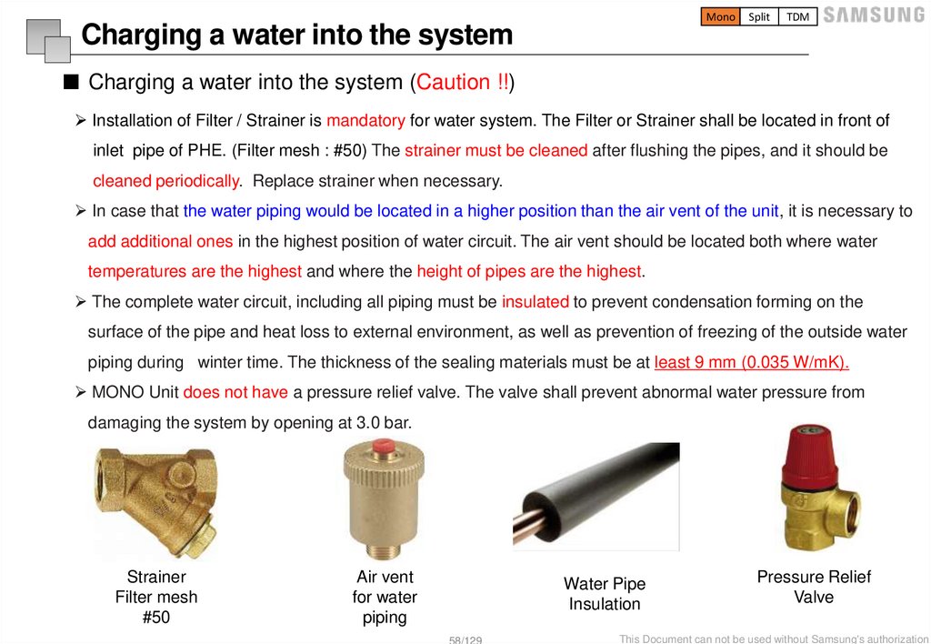
■ Charging a water into the system (Caution !!)
Installation of Filter / Strainer is mandatory for water system. The Filter or Strainer shall be located in front of
inlet pipe of PHE. (Filter mesh : #50) The strainer must be cleaned after flushing the pipes, and it should be
cleaned periodically. Replace strainer when necessary.
In case that the water piping would be located in a higher position than the air vent of the unit, it is necessary to
add additional ones in the highest position of water circuit. The air vent should be located both where water
temperatures are the highest and where the height of pipes are the highest.
The complete water circuit, including all piping must be insulated to prevent condensation forming on the
surface of the pipe and heat loss to external environment, as well as prevention of freezing of the outside water
piping during winter time. The thickness of the sealing materials must be at least 9 mm (0.035 W/mK).
MONO Unit does not have a pressure relief valve. The valve shall prevent abnormal water pressure from
damaging the system by opening at 3.0 bar.
Strainer
Filter mesh
#50
Air vent
for water
piping
Water Pipe
Insulation
58/129
Pressure Relief
Valve
This Document can not be used without Samsung's authorization
59.
MonoSplit
TDM
Charging a water into the system
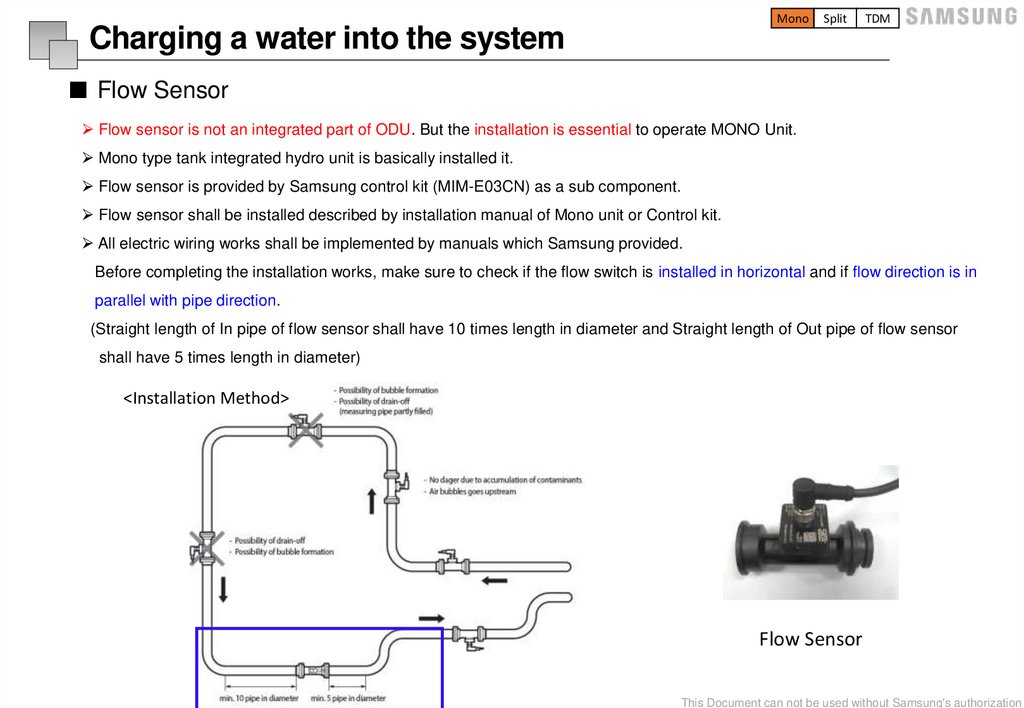
■ Flow Sensor
Flow sensor is not an integrated part of ODU. But the installation is essential to operate MONO Unit.
Mono type tank integrated hydro unit is basically installed it.
Flow sensor is provided by Samsung control kit (MIM-E03CN) as a sub component.
Flow sensor shall be installed described by installation manual of Mono unit or Control kit.
All electric wiring works shall be implemented by manuals which Samsung provided.
Before completing the installation works, make sure to check if the flow switch is installed in horizontal and if flow direction is in
parallel with pipe direction.
(Straight length of In pipe of flow sensor shall have 10 times length in diameter and Straight length of Out pipe of flow sensor
shall have 5 times length in diameter)
<Installation Method>
Flow Sensor
59/129
This Document can not be used without Samsung's authorization
60.
MonoSplit
TDM
Charging a water into the system
■ Freeze protection
Freeze protection solutions must use propylene glycol with a toxicity rating of Class 1 as listed in Clinical Toxicology of
Commercial Products, 5th Edition.
• Ethylene glycol is toxic and must not be used in the primary water circuit in case of any cross-contamination of the potable
circuit.
Freezing Points of Propylene Glycol – Water Mixtures
Propylene Glycol [wt. %] Freezing Point [°C] Propylene Glycol [wt. %] Freezing Point [°C]
※ Changing Glycol concentration can
cause pressure drop of the system and
it can reduce water flow rate.
0
0
36
-18
10
-3
40
-20
20
-7
43
-23
30
-12
48
-29
60/129
This Document can not be used without Samsung's authorization
61.
MonoSplit
TDM
Charging a water into the system
■ How to choose a expansion vessel
When it is required to change the default pre-pressure of the expansion vessel(1 bar), keep in mind the following guidelines:
Use only dry nitrogen to set the expansion vessel pre-pressure.
Improper setting of the expansion vessel pre-pressure will make malfunction of the system.
Therefore, the pre-pressure should be adjusted by a licensed installer.
Installation
Height
Difference
Water Volume
< 220 Litres
No pre-pressure adjustment
required
<7m
> 220 Litres
Actions required:
Pre-pressure must be decreased,
calculate according
To “Calculating the pre-pressure
of the expansion vessel”.
Check if the water volume is
lower than maximum allowed
Water volume
When Expansion vessel has a capacity 8 liters and 1bar pre-charged:
Water volume of total system for reliable performance is minimum 50liters.
>7 m
H
Pg ( 0.3)
10
Pg:
Pre-Pressure [bar]
H:
Maximum installation height difference
Actions required:
Pre-pressure must be
Expansion vessel of the unit too
increased, calculate the
Small for the installation.
appropriate value following
by “Calculating the pre-pressure
of the expansion vessel”.
Check if the water volume is
lower than maximum allowed
water volume
61/129
This Document can not be used without Samsung's authorization
62.
MonoSplit
TDM
Wiring
Rated
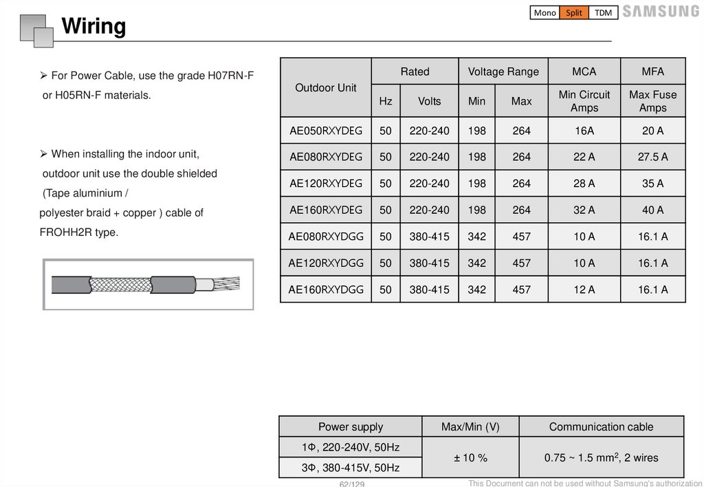
For Power Cable, use the grade H07RN-F
Voltage Range
Outdoor Unit
MCA
MFA
Hz
Volts
Min
Max
Min Circuit
Amps
Max Fuse
Amps
AE050RXYDEG
50
220-240
198
264
16A
20 A
AE080RXYDEG
50
220-240
198
264
22 A
27.5 A
AE120RXYDEG
50
220-240
198
264
28 A
35 A
polyester braid + copper ) cable of
AE160RXYDEG
50
220-240
198
264
32 A
40 A
FROHH2R type.
AE080RXYDGG
50
380-415
342
457
10 A
16.1 A
AE120RXYDGG
50
380-415
342
457
10 A
16.1 A
AE160RXYDGG
50
380-415
342
457
12 A
16.1 A
or H05RN-F materials.
When installing the indoor unit,
outdoor unit use the double shielded
(Tape aluminium /
Power supply
1Φ, 220-240V, 50Hz
Max/Min (V)
Communication cable
± 10 %
0.75 ~ 1.5 mm2, 2 wires
3Φ, 380-415V, 50Hz
62/129
This Document can not be used without Samsung's authorization
63.
External wiring and set up withHydro unit, Control kit
64.
MonoSplit
TDM
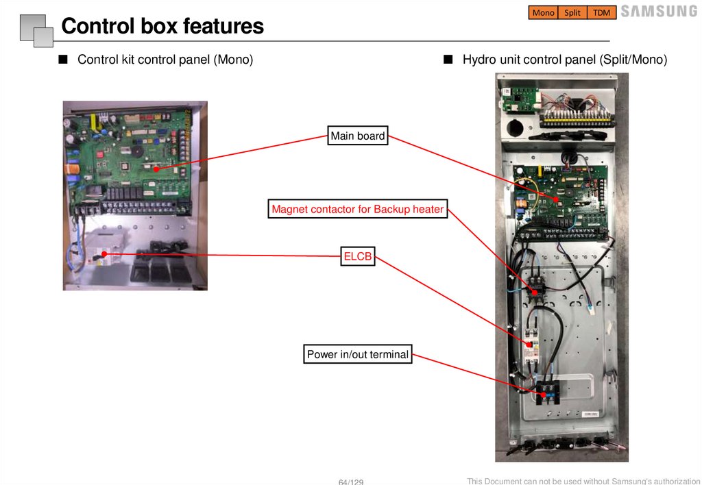
Control box features
■ Control kit control panel (Mono)
■ Hydro unit control panel (Split/Mono)
Main board
Magnet contactor for Backup heater
ELCB
Power in/out terminal
64/129
This Document can not be used without Samsung's authorization
65.
MonoSplit
TDM
Board features
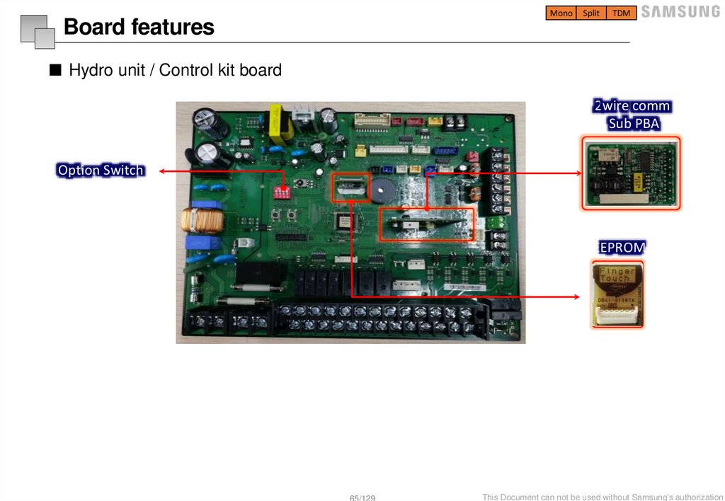
■ Hydro unit / Control kit board
2wire comm
Sub PBA
Option Switch
EEPROM
65/129
This Document can not be used without Samsung's authorization
66.
MonoSplit
TDM
Board features
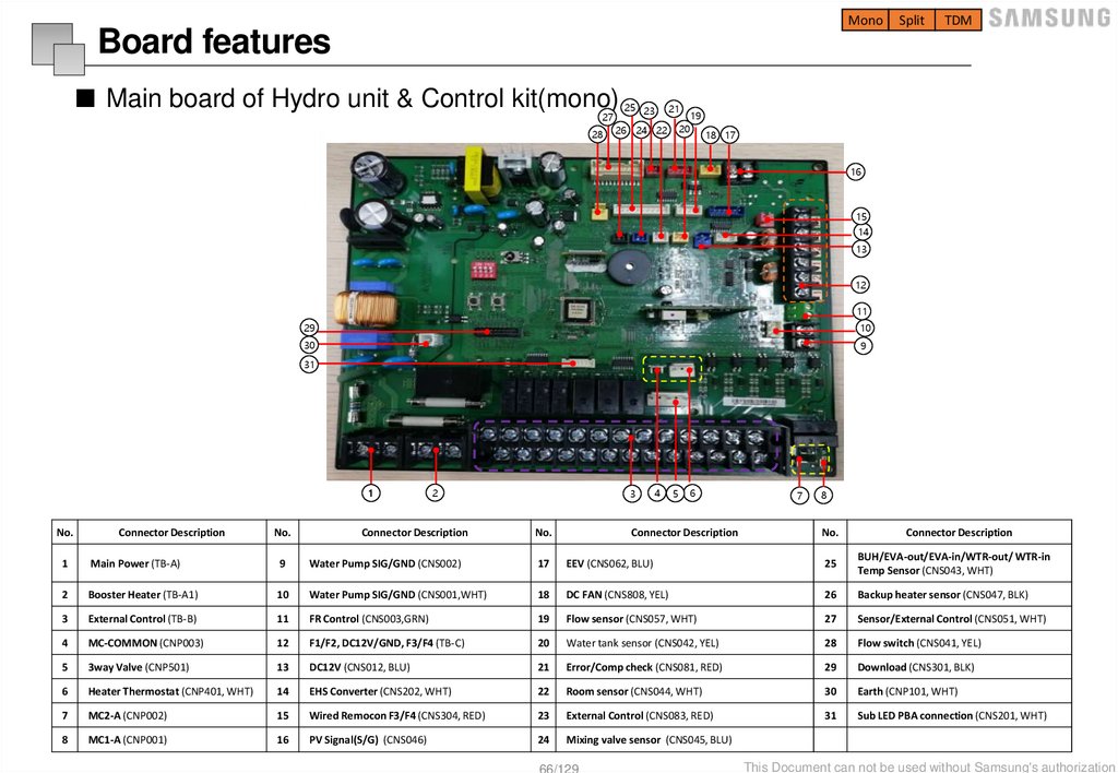
■ Main board of Hydro unit & Control kit(mono)
27
28
25 23
21
19
20
26 24 22
18 17
16
15
14
13
12
11
29
10
30
9
31
1
No.
Connector Description
2
3
No.
Connector Description
No.
4
5
6
Connector Description
7
8
No.
Connector Description
1
Main Power (TB-A)
9
Water Pump SIG/GND (CNS002)
17
EEV (CNS062, BLU)
25
BUH/EVA-out/EVA-in/WTR-out/ WTR-in
Temp Sensor (CNS043, WHT)
2
Booster Heater (TB-A1)
10
Water Pump SIG/GND (CNS001,WHT)
18
DC FAN (CNS808, YEL)
26
Backup heater sensor (CNS047, BLK)
3
External Control (TB-B)
11
FR Control (CNS003,GRN)
19
Flow sensor (CNS057, WHT)
27
Sensor/External Control (CNS051, WHT)
4
MC-COMMON (CNP003)
12
F1/F2, DC12V/GND, F3/F4 (TB-C)
20
Water tank sensor (CNS042, YEL)
28
Flow switch (CNS041, YEL)
5
3way Valve (CNP501)
13
DC12V (CNS012, BLU)
21
Error/Comp check (CNS081, RED)
29
Download (CNS301, BLK)
6
Heater Thermostat (CNP401, WHT)
14
EHS Converter (CNS202, WHT)
22
Room sensor (CNS044, WHT)
30
Earth (CNP101, WHT)
7
MC2-A (CNP002)
15
Wired Remocon F3/F4 (CNS304, RED)
23
External Control (CNS083, RED)
31
Sub LED PBA connection (CNS201, WHT)
8
MC1-A (CNP001)
16
PV Signal(S/G) (CNS046)
24
Mixing valve sensor (CNS045, BLU)
66/129
This Document can not be used without Samsung's authorization
67.
MonoSplit
TDM
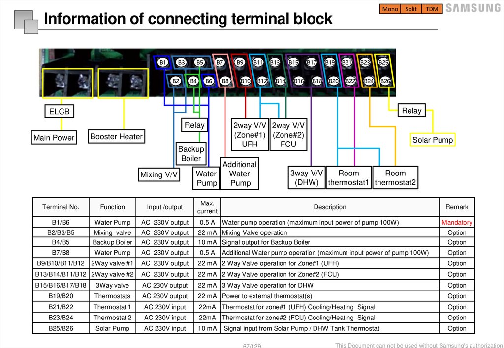
Information of connecting terminal block
B1
B3
B5
B2
B4
B7
B6
B9
B8
B11
B10
B12
B13
B14
B15
B17
B16
B18
B19
B21
B23
B25
B20
B22
B24
B26
Relay
ELCB
Relay
Main Power
Booster Heater
Backup
Boiler
Mixing V/V
2way V/V 2way V/V
(Zone#1) (Zone#2)
UFH
FCU
Additional
Water
Water
Pump
Pump
Solar Pump
Room
3way V/V
Room
(DHW) thermostat1 thermostat2
Terminal No.
Function
Input /output
Max.
current
B1/B6
Water Pump
AC 230V output
0.5 A
B2/B3/B5
B4/B5
Mixing valve
Backup Boiler
AC 230V output
AC 230V output
22 mA Mixing Valve operation
10 mA Signal output for Backup Boiler
Option
Option
B7/B8
Water Pump
AC 230V output
0.5 A
Option
B9/B10/B11/B12
2Way valve #1
AC 230V output
22 mA 2 Way Valve operation for Zone#1 (UFH)
Option
B13/B14/B11/B12 2Way valve #2
AC 230V output
22 mA 2 Way Valve operation for Zone#2 (FCU)
Option
B15/B16/B17/B18
3Way valve
AC 230V output
22 mA 3 Way Valve operation for DHW
Option
B19/B20
Thermostats
AC 230V output
22 mA Power to external thermostat(s)
Option
B21/B22
Thermostat 1
AC 230V input
22mA Thermostat for zone#1 (UFH) Cooling/Heating Signal
Option
B23/B24
Thermostat 2
AC 230V input
22mA Thermostat for zone#2 (FCU) Cooling/Heating Signal
Option
B25/B26
Solar Pump
AC 230V input
10 mA
Option
Description
Water pump operation (maximum input power of pump 100W)
Additional Water pump operation (maximum input power of pump 100W)
Signal input from Solar Pump / DHW Tank Thermostat
67/129
Remark
Mandatory
This Document can not be used without Samsung's authorization
68.
MonoSplit
TDM
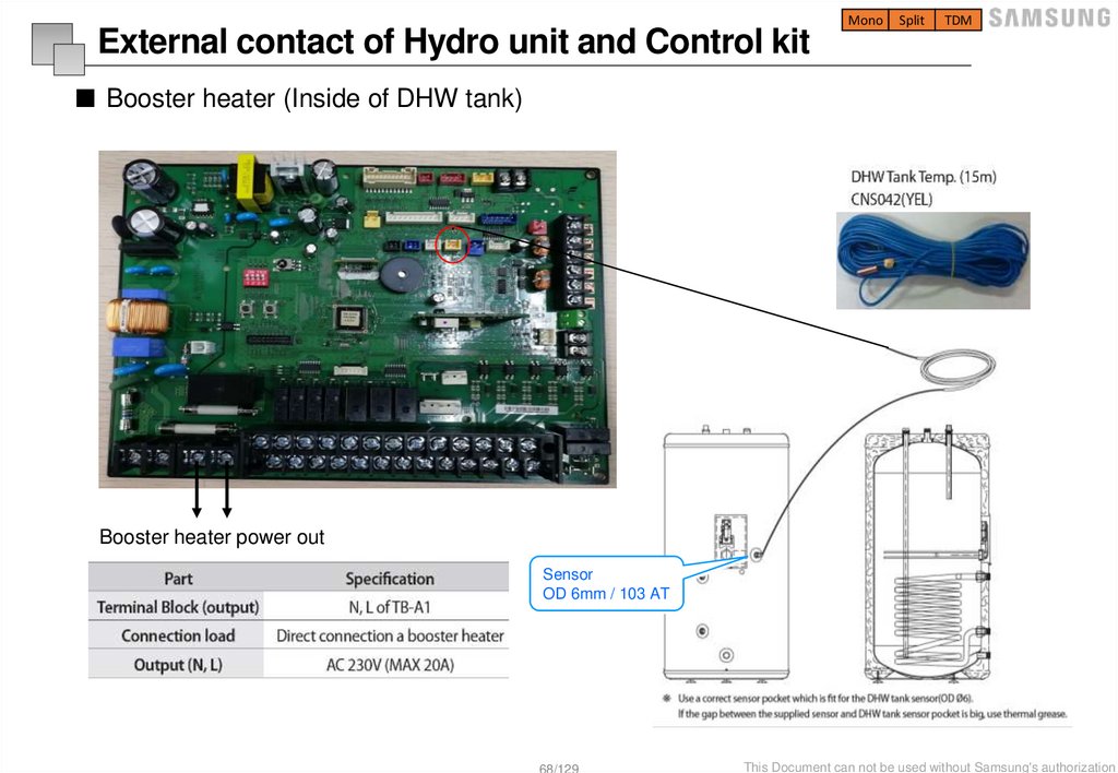
External contact of Hydro unit and Control kit
■ Booster heater (Inside of DHW tank)
Booster heater power out
Sensor
OD 6mm / 103 AT
68/129
This Document can not be used without Samsung's authorization
69.
MonoSplit
TDM
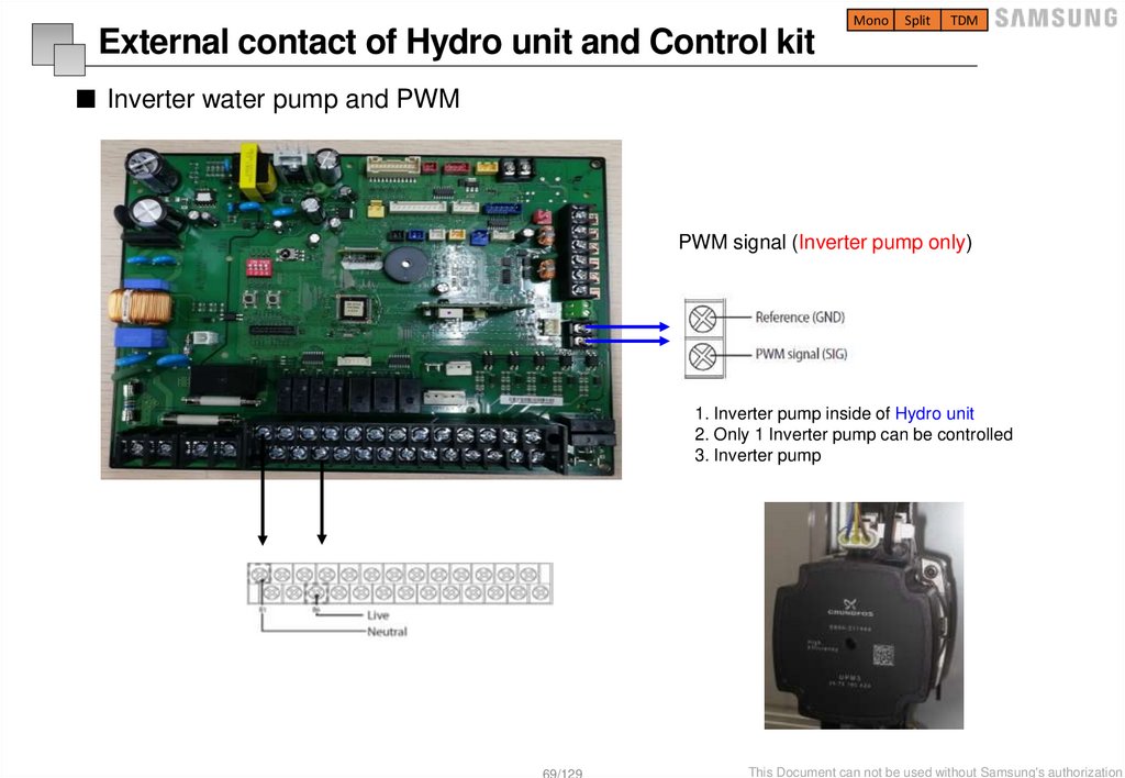
External contact of Hydro unit and Control kit
■ Inverter water pump and PWM
PWM signal (Inverter pump only)
1. Inverter pump inside of Hydro unit
2. Only 1 Inverter pump can be controlled
3. Inverter pump
69/129
This Document can not be used without Samsung's authorization
70.
MonoSplit
TDM
External contact information
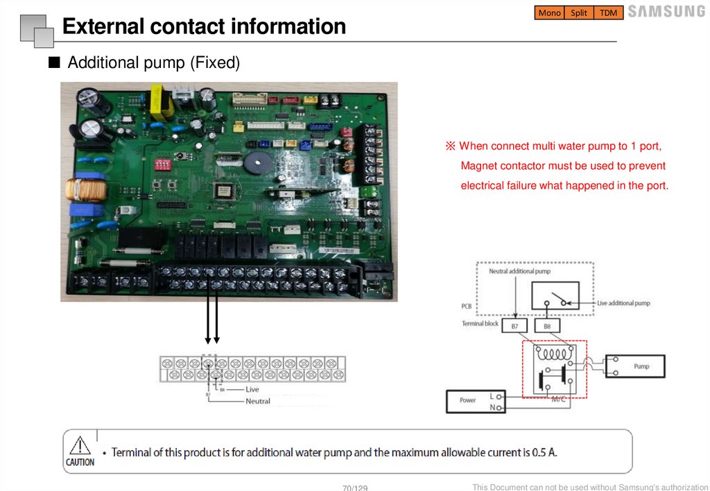
■ Additional pump (Fixed)
※ When connect multi water pump to 1 port,
Magnet contactor must be used to prevent
electrical failure what happened in the port.
70/129
This Document can not be used without Samsung's authorization
71.
MonoSplit
TDM
External contact information
■ Mixing valve
※ Hydro unit or Control kit power should be turned off before the installation.
TW3
TW4
Select a mixing valve as recommended and install at the entrance position of each zone
71/129
This Document can not be used without Samsung's authorization
72.
MonoSplit
TDM
External contact information
■ Mixing valve temperature sensor
TW3
TW4
72/129
This Document can not be used without Samsung's authorization
73.
MonoSplit
TDM
External contact information
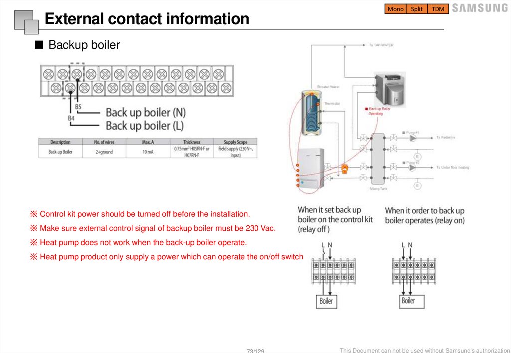
■ Backup boiler
※ Control kit power should be turned off before the installation.
※ Make sure external control signal of backup boiler must be 230 Vac.
※ Heat pump does not work when the back-up boiler operate.
※ Heat pump product only supply a power which can operate the on/off switch
73/129
This Document can not be used without Samsung's authorization
74.
MonoSplit
TDM
External contact information
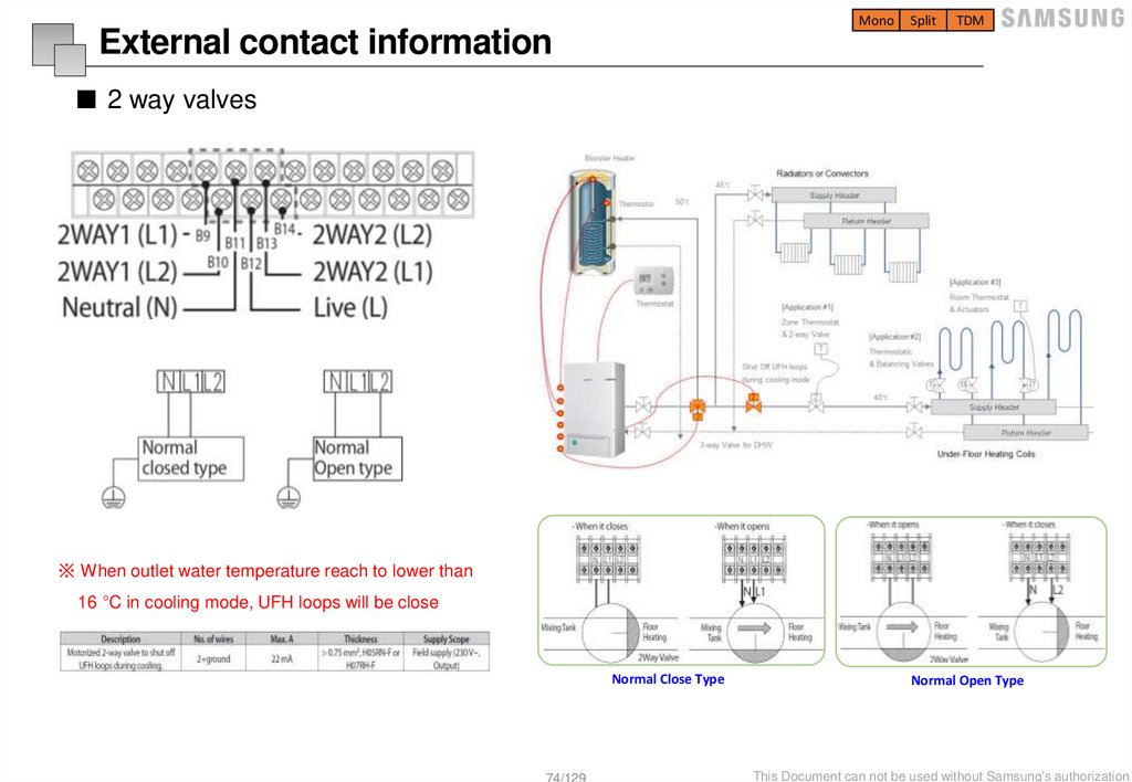
■ 2 way valves
※ When outlet water temperature reach to lower than
16 °C in cooling mode, UFH loops will be close
Normal Close Type
74/129
Normal Open Type
This Document can not be used without Samsung's authorization
75.
MonoSplit
TDM
External contact information
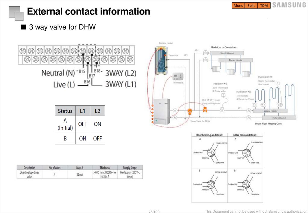
■ 3 way valve for DHW
75/129
This Document can not be used without Samsung's authorization
76.
MonoSplit
TDM
External contact information
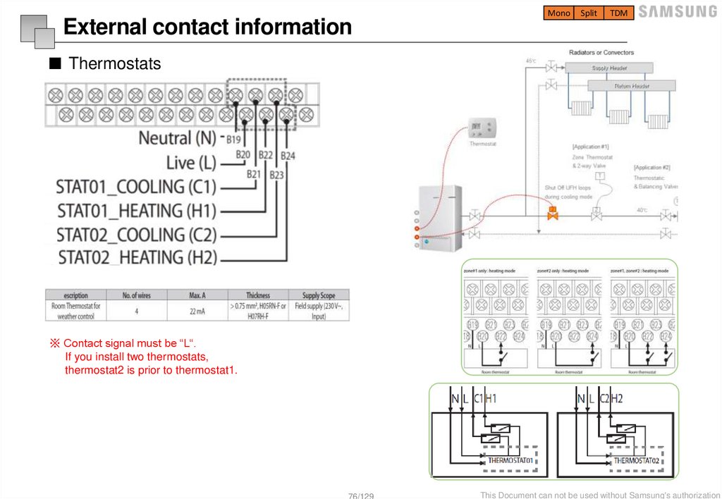
■ Thermostats
※ Contact signal must be “L“.
If you install two thermostats,
thermostat2 is prior to thermostat1.
76/129
This Document can not be used without Samsung's authorization
77.
MonoSplit
TDM
External contact information
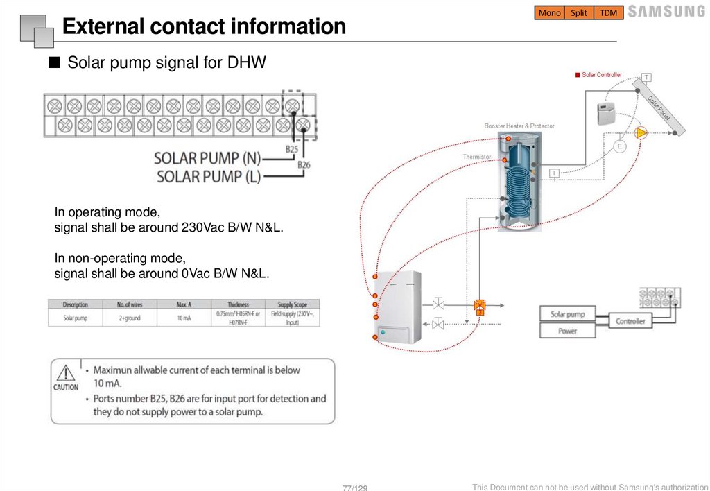
■ Solar pump signal for DHW
In operating mode,
signal shall be around 230Vac B/W N&L.
In non-operating mode,
signal shall be around 0Vac B/W N&L.
77/129
This Document can not be used without Samsung's authorization
78.
MonoSplit
TDM
External contact information
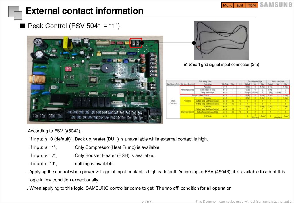
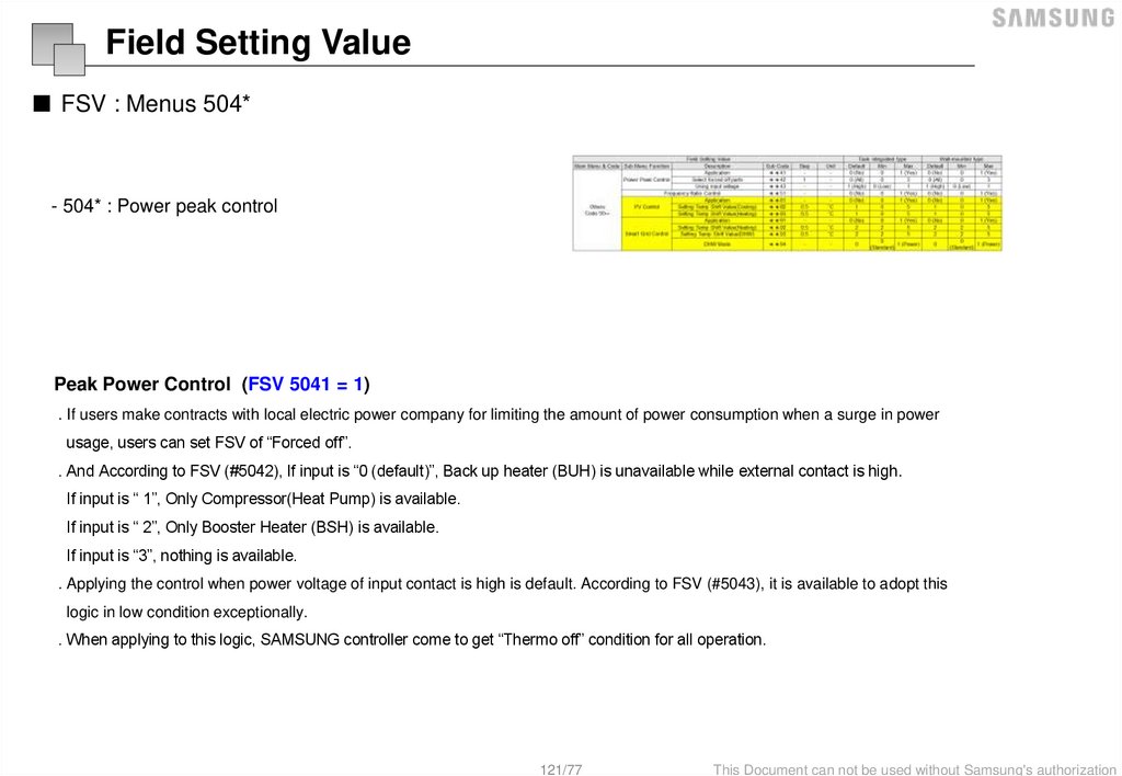
■ Peak Control (FSV 5041 = “1”)
※ Smart grid signal input connector (2m)
. According to FSV (#5042),
If input is “0 (default)”, Back up heater (BUH) is unavailable while external contact is high.
If input is “ 1”,
Only Compressor(Heat Pump) is available.
If input is “ 2”,
Only Booster Heater (BSH) is available.
If input is “3”,
nothing is available.
. Applying the control when power voltage of input contact is high is default. According to FSV (#5043), it is available to adopt this
logic in low condition exceptionally.
. When applying to this logic, SAMSUNG controller come to get “Thermo off” condition for all operation.
78/129
This Document can not be used without Samsung's authorization
79.
MonoSplit
TDM
External contact information
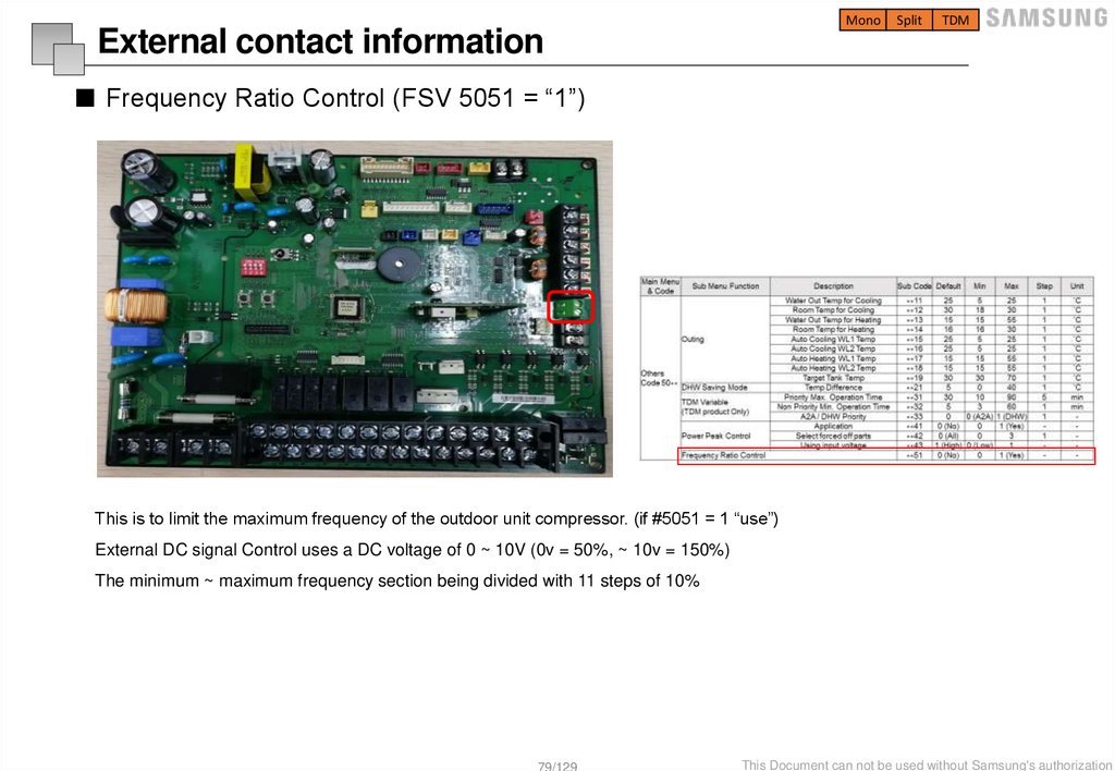
■ Frequency Ratio Control (FSV 5051 = “1”)
This is to limit the maximum frequency of the outdoor unit compressor. (if #5051 = 1 “use”)
External DC signal Control uses a DC voltage of 0 ~ 10V (0v = 50%, ~ 10v = 150%)
The minimum ~ maximum frequency section being divided with 11 steps of 10%
79/129
This Document can not be used without Samsung's authorization
80.
Switches of unit81.
MonoSplit
TDM
Switch configuration
■ Outdoor unit main board feature
Optional item
Case I
Case II
Picture
1 main PCB
Applied model
AE 080, 090, 120, 160**
(outdoor unit)
1 main PCB
AE 040, 050, 060**
(outdoor unit)
81/129
This Document can not be used without Samsung's authorization
82.
MonoSplit
TDM
Switch configuration
■ Outdoor unit main board – Tact switches
Case study )
K2 x 2 = The inverter checker mode.
Sequence is as follows.
Wait 10 seconds -> During 5 second, the checked mode transmission
with the inverter -> wait 5 seconds
(The checked mode transmission release) -> key operation release
82/129
This Document can not be used without Samsung's authorization
83.
MonoSplit
TDM
Switch configuration
■ Outdoor unit main board – View mode by k4 tact switch
83/129
This Document can not be used without Samsung's authorization
84.
MonoSplit
TDM
Option setting
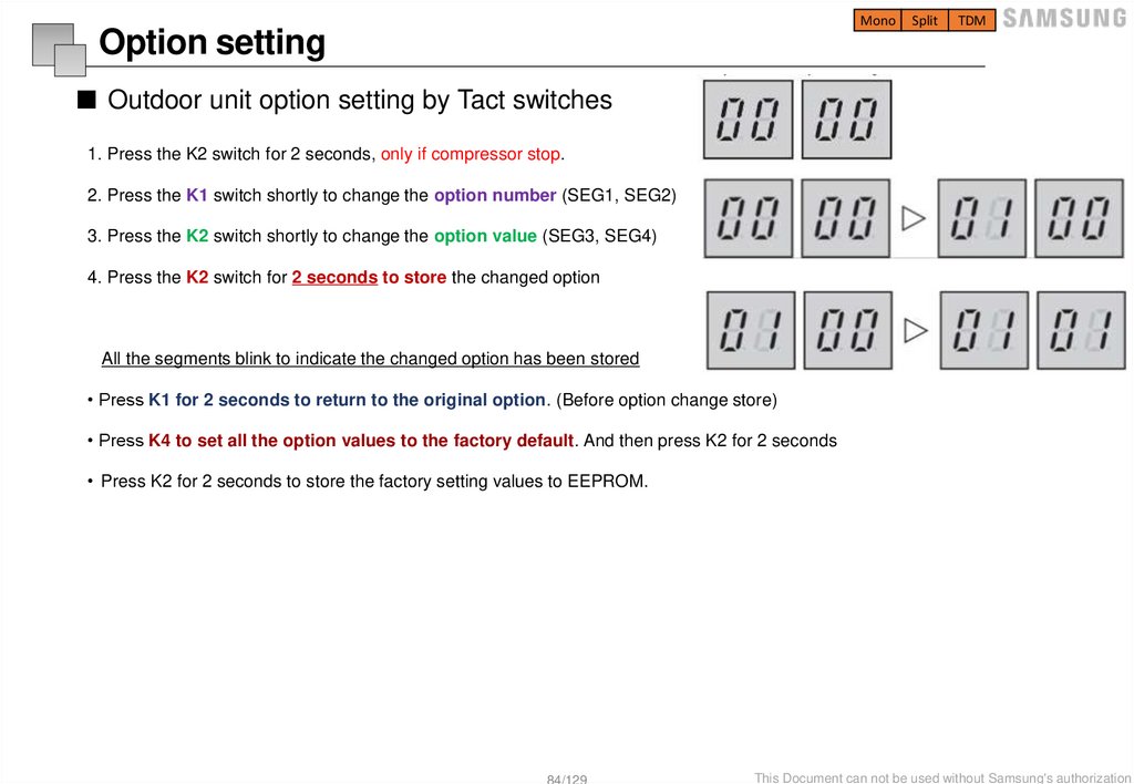
■ Outdoor unit option setting by Tact switches
1. Press the K2 switch for 2 seconds, only if compressor stop.
2. Press the K1 switch shortly to change the option number (SEG1, SEG2)
3. Press the K2 switch shortly to change the option value (SEG3, SEG4)
4. Press the K2 switch for 2 seconds to store the changed option
All the segments blink to indicate the changed option has been stored
• Press K1 for 2 seconds to return to the original option. (Before option change store)
• Press K4 to set all the option values to the factory default. And then press K2 for 2 seconds
• Press K2 for 2 seconds to store the factory setting values to EEPROM.
84/129
This Document can not be used without Samsung's authorization
85.
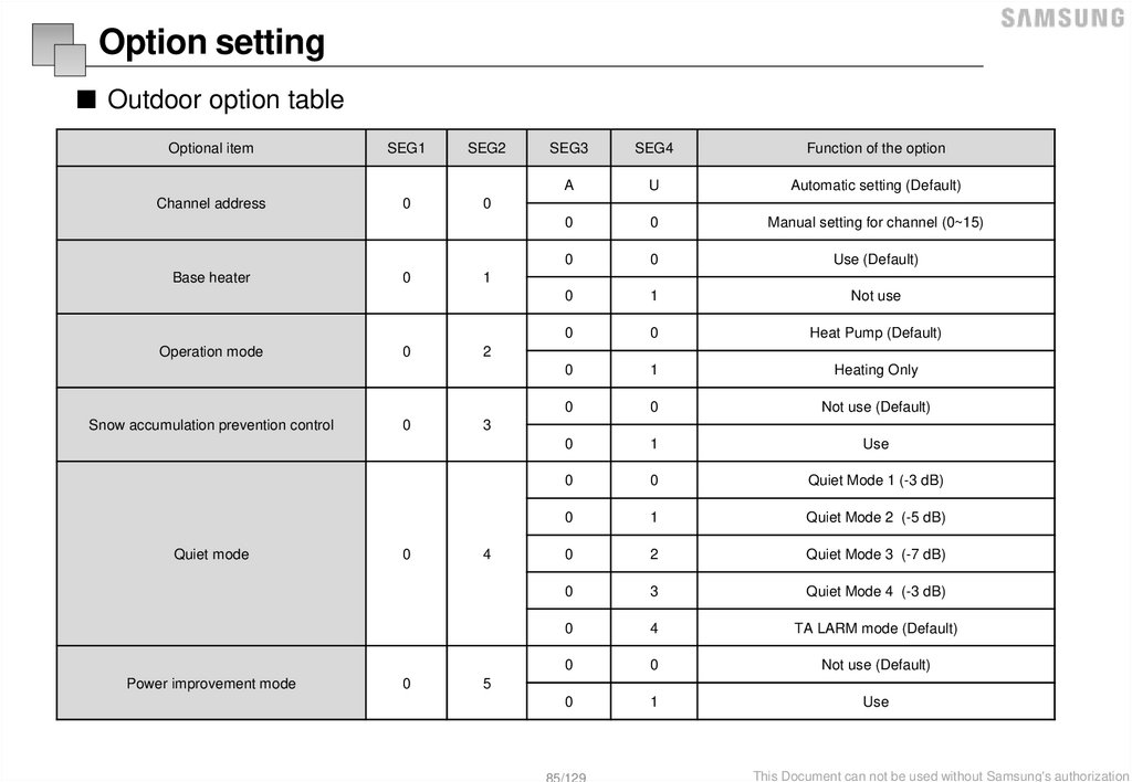
Option setting■ Outdoor option table
Optional item
SEG1
SEG2
Channel address
0
0
Base heater
Operation mode
Snow accumulation prevention control
Quiet mode
Power improvement mode
0
0
0
0
0
SEG3
SEG4
Function of the option
A
U
Automatic setting (Default)
0
0
Manual setting for channel (0~15)
0
0
Use (Default)
0
1
Not use
0
0
Heat Pump (Default)
0
1
Heating Only
0
0
Not use (Default)
0
1
Use
0
0
Quiet Mode 1 (-3 dB)
0
1
Quiet Mode 2 (-5 dB)
0
2
Quiet Mode 3 (-7 dB)
0
3
Quiet Mode 4 (-3 dB)
0
4
TA LARM mode (Default)
0
0
Not use (Default)
0
1
Use
1
2
3
4
5
85/129
This Document can not be used without Samsung's authorization
86.
MonoSplit
TDM
Option setting
■ Hydro unit / Control kit – Dip switches
KEY
ON (Default)
OFF
Remark
DIP 1
Normal Operation
Emergency Heating Operation
DIP 2
Normal Operation
Emergency DHW Operation
When both DIP 1 and 2 are OFF at the same time,
EHS operate emergency heating mode
DIP 3
Normal Operation
Concrete Curing Function
If you set Dip S/W #4 off in the hydro unit, then the
DIP 4
Normal Operation
Outdoor unit power off ->on
Error code modification
86/129
Error E101 still there but After outdoor unit power get
back the error will go away. -> can run
This Document can not be used without Samsung's authorization
87.
MonoSplit
TDM
Option setting
■ Hydro unit / Control kit – Dip switches (Emergency space heating operation)
Space Heating
Dip S/W #1 OFF (Control PBA)
Activation
FSV #4031 =1 (Backup heater available)
Heat Source
Back up Heater 2nd stage
Display
Show ‘E-op’ on the Schedule Display
3way valve
Room Direction Only
2way valve
No Zone Control, always open
Water Pump
Following water pump logic under TW2 Control.
(ex. 3min-ON, 2min OFF after Thermo off)
Thermo OFF
Tw3 ≥ Ts + 2.0°C
Thermo ON
Tw3 < Ts – 2.0°C
Allowed
E911,E912, Outing Mode, Water Pump, Flow Switch,
Anti Freeze, Antipump lock, Electricity failure recovery
Not Allowed or ignoring
Auto, Schedule, Silence, urgent DHW, Disinfection, Tr Control, Thermostat Control,
Outdoor unit communication, Back up Boiler, Smart Grid, Eco Level, Viewing Outdoor
temperature, Zone Control
87/129
This Document can not be used without Samsung's authorization
88.
MonoSplit
TDM
Option setting
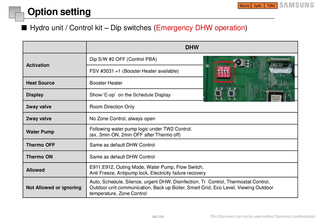
■ Hydro unit / Control kit – Dip switches (Emergency DHW operation)
DHW
Dip S/W #2 OFF (Control PBA)
Activation
FSV #3031 =1 (Booster Heater available)
Heat Source
Booster Heater
Display
Show ‘E-op’ on the Schedule Display
3way valve
Room Direction Only
2way valve
No Zone Control, always open
Water Pump
Following water pump logic under TW2 Control.
(ex. 3min-ON, 2min OFF after Thermo off)
Thermo OFF
Same as default DHW Control
Thermo ON
Same as default DHW Control
Allowed
E911,E912, Outing Mode, Water Pump, Flow Switch,
Anti Freeze, Antipump lock, Electricity failure recovery
Not Allowed or ignoring
Auto, Schedule, Silence, urgent DHW, Disinfection, Tr Control, Thermostat Control,
Outdoor unit communication, Back up Boiler, Smart Grid, Eco Level, Viewing Outdoor
temperature, Zone Control
88/129
This Document can not be used without Samsung's authorization
89.
MonoSplit
TDM
Option setting
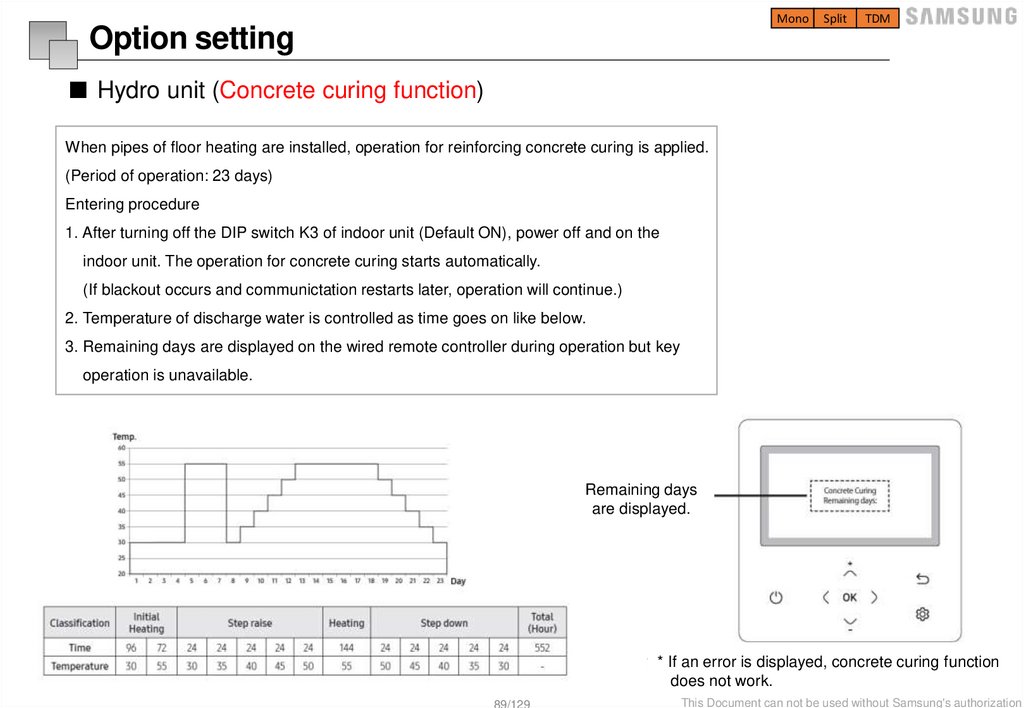
■ Hydro unit (Concrete curing function)
When pipes of floor heating are installed, operation for reinforcing concrete curing is applied.
(Period of operation: 23 days)
Entering procedure
1. After turning off the DIP switch K3 of indoor unit (Default ON), power off and on the
indoor unit. The operation for concrete curing starts automatically.
(If blackout occurs and communictation restarts later, operation will continue.)
2. Temperature of discharge water is controlled as time goes on like below.
3. Remaining days are displayed on the wired remote controller during operation but key
operation is unavailable.
Remaining days
are displayed.
* If an error is displayed, concrete curing function
does not work.
89/129
This Document can not be used without Samsung's authorization
90.
Field Setting Value91.
MonoSplit
TDM
Service mode Setting
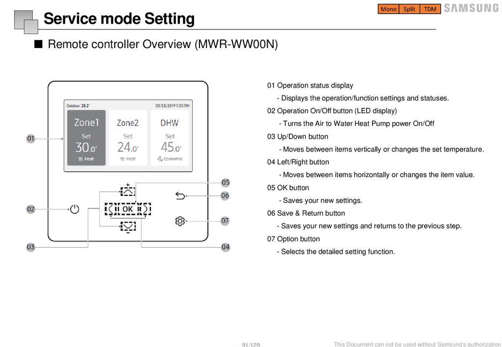
■ Remote controller Overview (MWR-WW00N)
01 Operation status display
- Displays the operation/function settings and statuses.
02 Operation On/Off button (LED display)
- Turns the Air to Water Heat Pump power On/Off
03 Up/Down button
- Moves between items vertically or changes the set temperature.
04 Left/Right button
- Moves between items horizontally or changes the item value.
05 OK button
- Saves your new settings.
06 Save & Return button
- Saves your new settings and returns to the previous step.
07 Option button
- Selects the detailed setting function.
91/129
This Document can not be used without Samsung's authorization
92.
MonoSplit
TDM
Service mode Setting
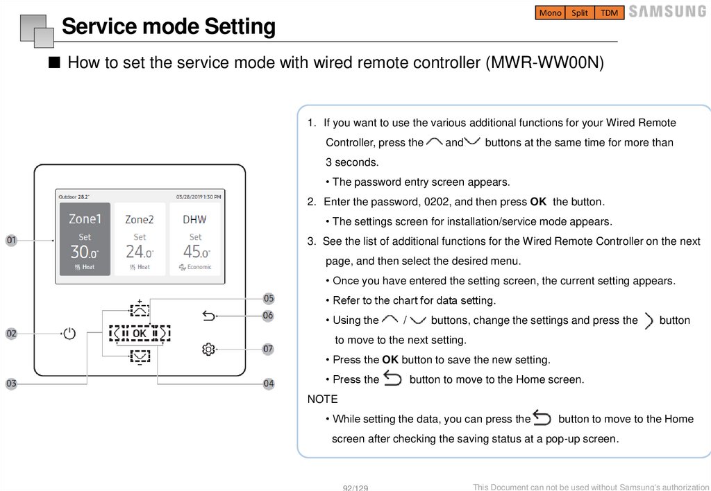
■ How to set the service mode with wired remote controller (MWR-WW00N)
1. If you want to use the various additional functions for your Wired Remote
Controller, press the
and
buttons at the same time for more than
3 seconds.
• The password entry screen appears.
2. Enter the password, 0202, and then press OK the button.
• The settings screen for installation/service mode appears.
3. See the list of additional functions for the Wired Remote Controller on the next
page, and then select the desired menu.
• Once you have entered the setting screen, the current setting appears.
• Refer to the chart for data setting.
• Using the
/
buttons, change the settings and press the
button
to move to the next setting.
• Press the OK button to save the new setting.
• Press the
button to move to the Home screen.
NOTE
• While setting the data, you can press the
button to move to the Home
screen after checking the saving status at a pop-up screen.
92/129
This Document can not be used without Samsung's authorization
93.
MonoSplit
TDM
Service mode Setting
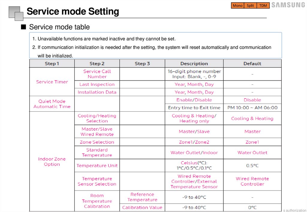
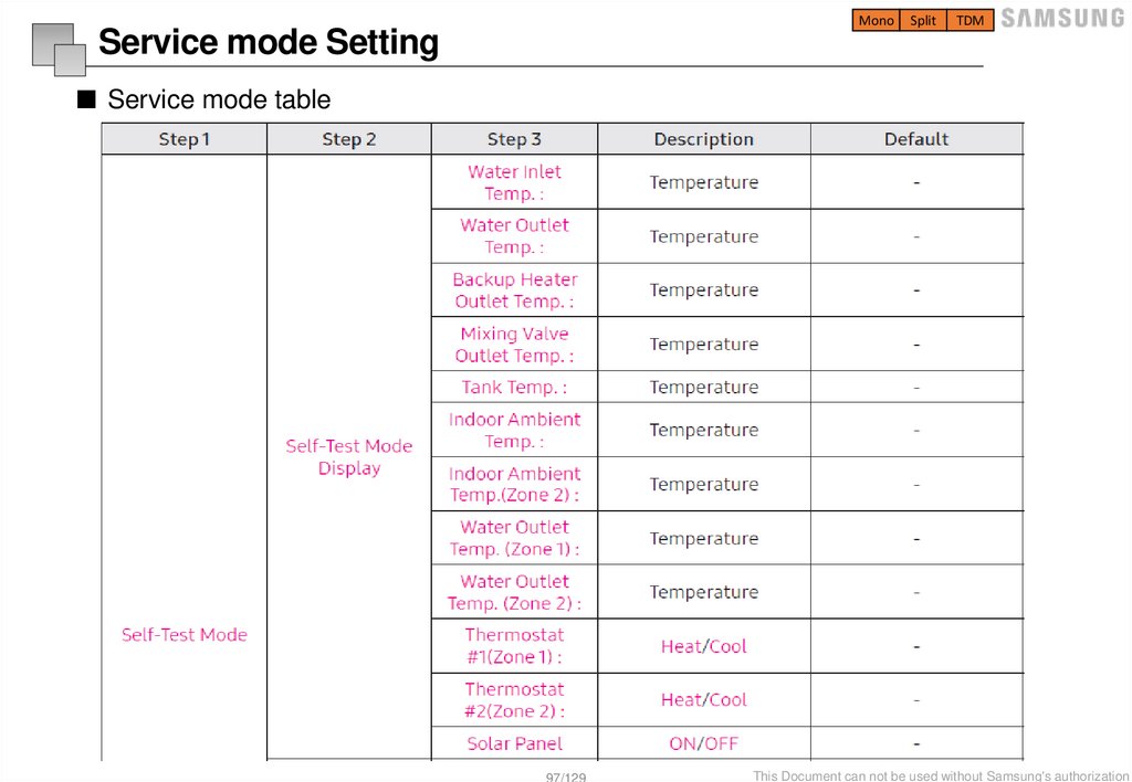
■ Service mode table
1. Unavailable functions are marked inactive and they cannot be set.
2. If communication initialization is needed after the setting, the system will reset automatically and communication
will be initialized.
93/129
This Document can not be used without Samsung's authorization
94.
MonoSplit
TDM
Service mode Setting
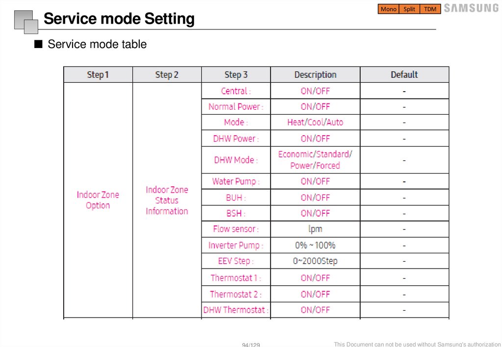
■ Service mode table
94/129
This Document can not be used without Samsung's authorization
95.
MonoSplit
TDM
Service mode Setting
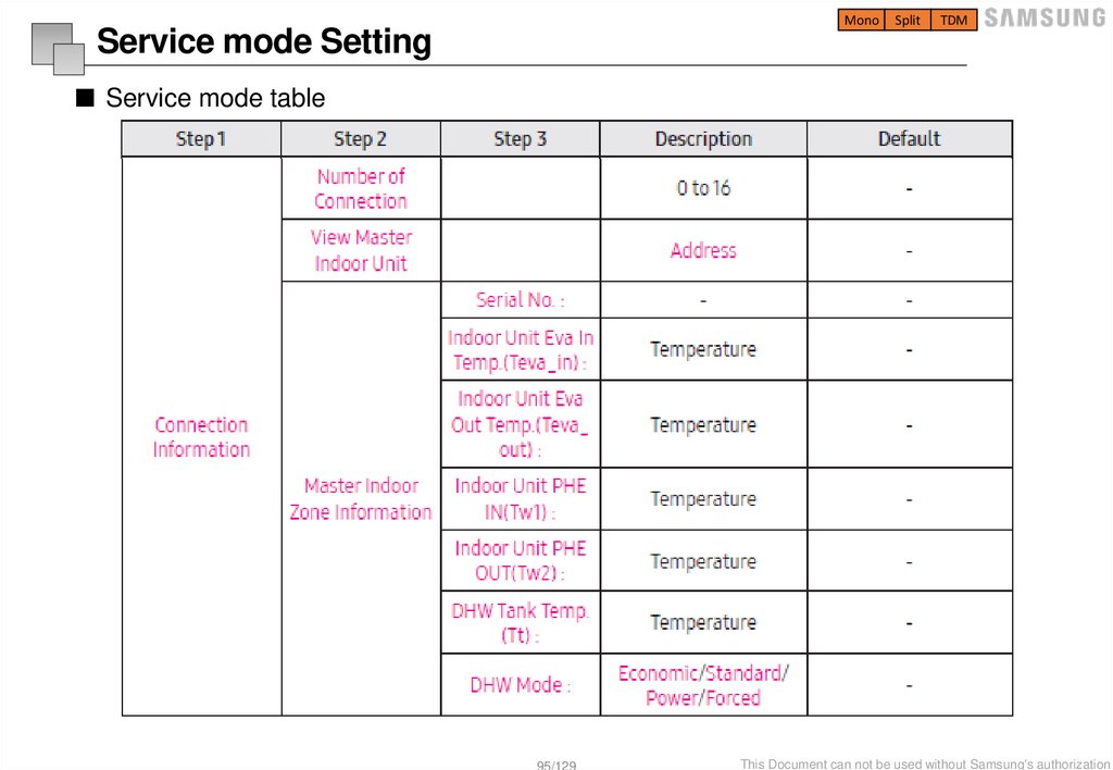
■ Service mode table
95/129
This Document can not be used without Samsung's authorization
96.
MonoSplit
TDM
Service mode Setting
■ Service mode table
96/129
This Document can not be used without Samsung's authorization
97.
MonoSplit
TDM
Service mode Setting
■ Service mode table
97/129
This Document can not be used without Samsung's authorization
98.
MonoSplit
TDM
Service mode Setting
■ Service mode table
98/129
This Document can not be used without Samsung's authorization
99.
MonoSplit
TDM
Service mode Setting
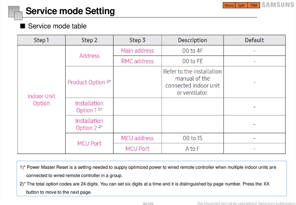
■ Service mode table
1)* Power Master Reset is a setting needed to supply optimized power to wired remote controller when multiple indoor units are
connected to wired remote controller in a group.
2)* The total option codes are 24 digits. You can set six digits at a time and it is distinguished by page number. Press the XX
button to move to the next page.
99/129
This Document can not be used without Samsung's authorization
100.
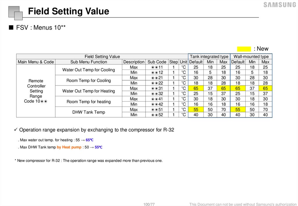
Field Setting Value■ FSV : Menus 10**
: New
Main Menu & Code
Remote
Controller
Setting
Range
Code 10✴✴
Field Setting Value
Tank integrated type Wall-mounted type
Sub Menu Function
Description Sub Code Step Unit Default Min Max Default Min Max
Max
1
˚C
25
18
25
25
18
25
✴✴11
Water Out Temp for Cooling
Min
1
˚C
16
5
18
16
5
18
✴✴12
Max
21
1
˚C
30
28
30
30
28
30
✴✴
Room Temp for Cooling
Min
1
˚C
18
18
28
18
18
28
✴✴22
Max
31
1
˚C
65
37
65
65
37
65
✴✴
Water Out Temp for Heating
Min
1
˚C
25
15
37
25
15
37
✴✴32
Max
1
˚C
30
18
30
30
18
30
✴✴41
Room Temp for heating
Min
1
˚C
16
16
18
16
16
18
✴✴42
Max
1
˚C
55
50
70
55
50
70
✴✴51
DHW Tank Temp
Min
1
˚C
40
30
40
40
30
40
✴✴52
Operation range expansion by exchanging to the compressor for R-32
. Max water out temp. for heating : 55 → 65℃
. Max DHW Tank temp by Heat pump : 50 → 55℃
* New compressor for R-32 : The operation range was expanded more than previous one.
100/77
This Document can not be used without Samsung's authorization
101.
Field Setting Value■ FSV : Menus 10**
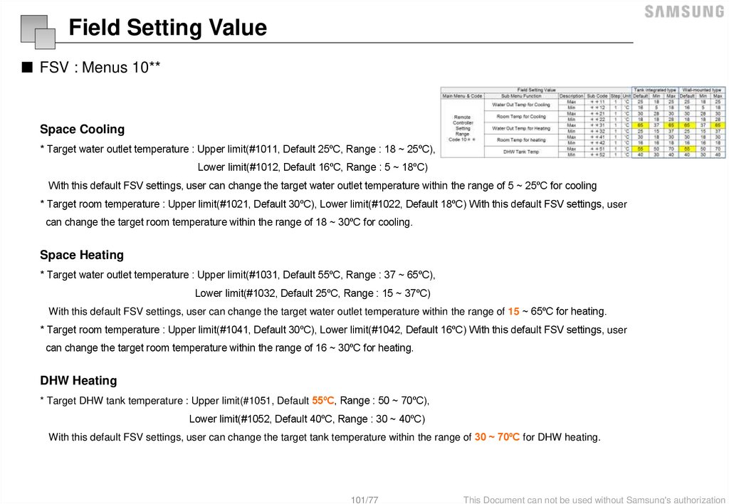
Space Cooling
* Target water outlet temperature : Upper limit(#1011, Default 25ºC, Range : 18 ~ 25ºC),
Lower limit(#1012, Default 16ºC, Range : 5 ~ 18ºC)
With this default FSV settings, user can change the target water outlet temperature within the range of 5 ~ 25ºC for cooling
* Target room temperature : Upper limit(#1021, Default 30ºC), Lower limit(#1022, Default 18ºC) With this default FSV settings, user
can change the target room temperature within the range of 18 ~ 30ºC for cooling.
Space Heating
* Target water outlet temperature : Upper limit(#1031, Default 55ºC, Range : 37 ~ 65ºC),
Lower limit(#1032, Default 25ºC, Range : 15 ~ 37ºC)
With this default FSV settings, user can change the target water outlet temperature within the range of 15 ~ 65ºC for heating.
* Target room temperature : Upper limit(#1041, Default 30ºC), Lower limit(#1042, Default 16ºC) With this default FSV settings, user
can change the target room temperature within the range of 16 ~ 30ºC for heating.
DHW Heating
* Target DHW tank temperature : Upper limit(#1051, Default 55ºC, Range : 50 ~ 70ºC),
Lower limit(#1052, Default 40ºC, Range : 30 ~ 40ºC)
With this default FSV settings, user can change the target tank temperature within the range of 30 ~ 70ºC for DHW heating.
101/77
This Document can not be used without Samsung's authorization
102.
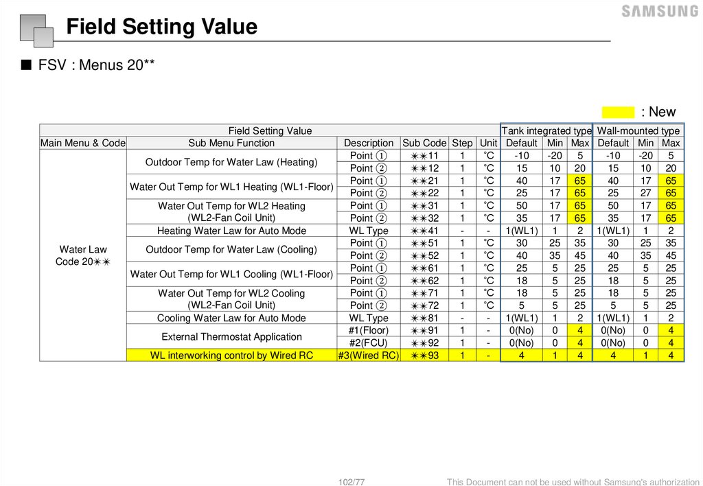
Field Setting Value■ FSV : Menus 20**
: New
Main Menu & Code
Water Law
Code 20✴✴
Field Setting Value
Sub Menu Function
Tank integrated type Wall-mounted type
Description Sub Code Step Unit Default Min Max Default Min Max
Point ①
1
˚C
-10
-20
5
-10
-20
5
✴✴11
Outdoor Temp for Water Law (Heating)
Point ②
1
˚C
15
10 20
15
10 20
✴✴12
Point ①
1
˚C
40
17 65
40
17 65
✴✴21
Water Out Temp for WL1 Heating (WL1-Floor)
Point ②
1
˚C
25
17 65
25
27 65
✴✴22
Point ①
1
˚C
50
17 65
50
17 65
Water Out Temp for WL2 Heating
✴✴31
(WL2-Fan Coil Unit)
Point ②
1
˚C
35
17 65
35
17 65
✴✴32
Heating Water Law for Auto Mode
WL Type
41
1(WL1)
1
2
1(WL1)
1
2
✴✴
Point ①
1
˚C
30
25 35
30
25 35
✴✴51
Outdoor Temp for Water Law (Cooling)
Point ②
52
1
˚C
40
35
45
40
35 45
✴✴
Point ①
1
˚C
25
5
25
25
5
25
✴✴61
Water Out Temp for WL1 Cooling (WL1-Floor)
Point ②
1
˚C
18
5
25
18
5
25
✴✴62
Point ①
1
˚C
18
5
25
18
5
25
Water Out Temp for WL2 Cooling
✴✴71
(WL2-Fan Coil Unit)
Point ②
1
˚C
5
5
25
5
5
25
✴✴72
Cooling Water Law for Auto Mode
WL Type
1(WL1) 1
2 1(WL1) 1
2
✴✴81
#1(Floor)
1
0(No)
0
4
0(No)
0
4
✴✴91
External Thermostat Application
#2(FCU)
1
0(No)
0
4
0(No)
0
4
✴✴92
WL interworking control by Wired RC
#3(Wired RC) ✴✴93
1
4
1
4
4
1
4
102/77
This Document can not be used without Samsung's authorization
103.
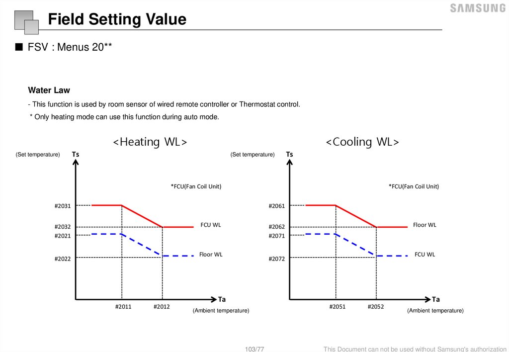
Field Setting Value■ FSV : Menus 20**
Water Law
- This function is used by room sensor of wired remote controller or Thermostat control.
* Only heating mode can use this function during auto mode.
<Heating WL>
(Set temperature)
<Cooling WL>
Ts
(Set temperature)
Ts
*FCU(Fan Coil Unit)
*FCU(Fan Coil Unit)
#2031
#2061
FCU WL
#2032
#2021
Floor WL
#2022
Floor WL
#2062
#2071
FCU WL
#2072
Ta
#2011
#2012
Ta
(Ambient temperature)
103/77
#2051
#2052
(Ambient temperature)
This Document can not be used without Samsung's authorization
104.
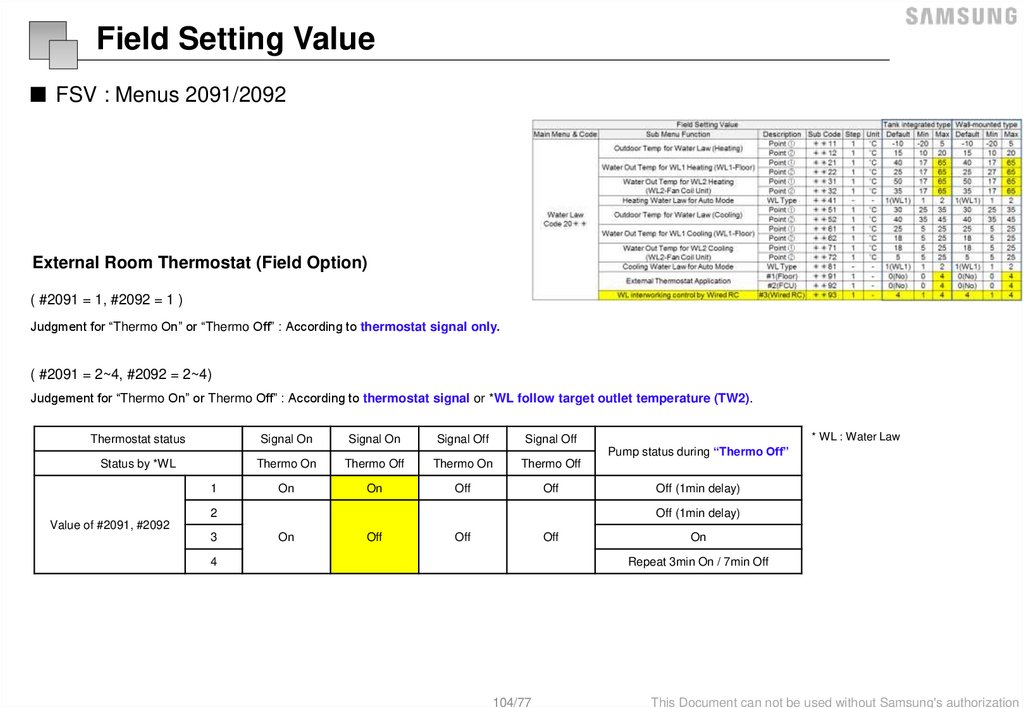
Field Setting Value■ FSV : Menus 2091/2092
External Room Thermostat (Field Option)
( #2091 = 1, #2092 = 1 )
Judgment for “Thermo On” or “Thermo Off” : According to thermostat signal only.
( #2091 = 2~4, #2092 = 2~4)
Judgement for “Thermo On” or Thermo Off” : According to thermostat signal or *WL follow target outlet temperature (TW2).
Thermostat status
Signal On
Signal On
Signal Off
Signal Off
Status by *WL
Thermo On
Thermo Off
Thermo On
Thermo Off
On
On
Off
Off
1
2
* WL : Water Law
Pump status during “Thermo Off”
Off (1min delay)
Off (1min delay)
Value of #2091, #2092
3
On
Off
Off
Off
4
On
Repeat 3min On / 7min Off
104/77
This Document can not be used without Samsung's authorization
105.
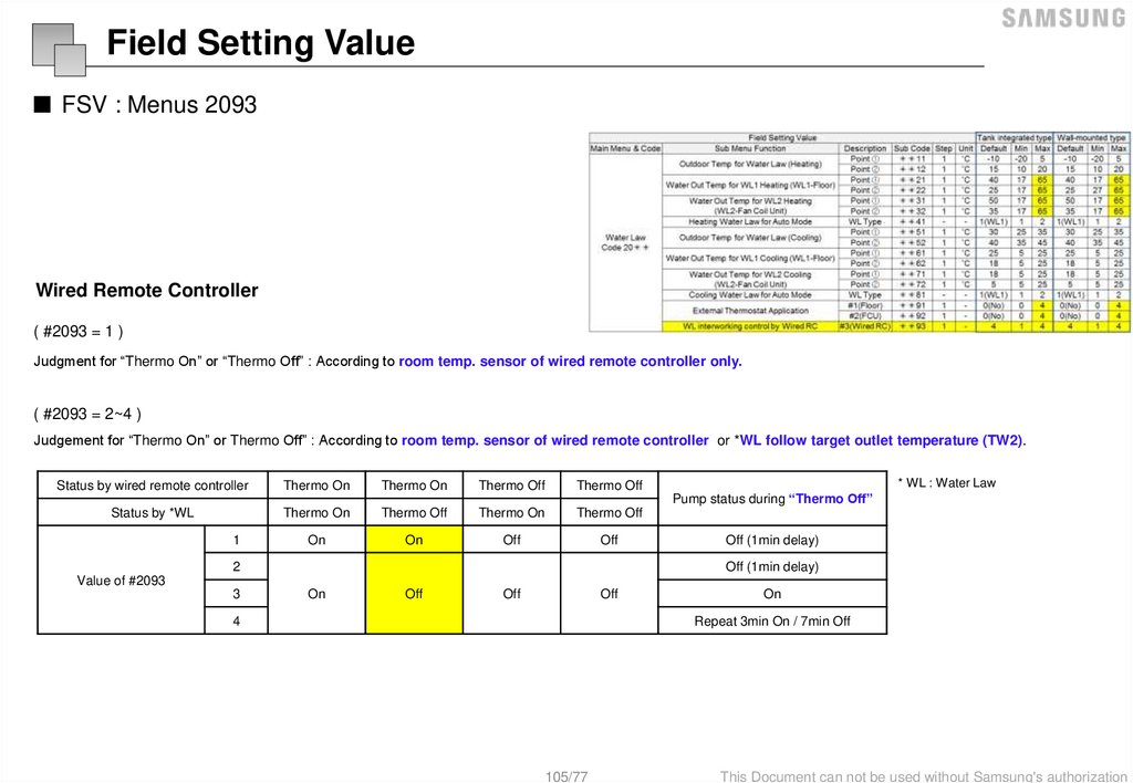
Field Setting Value■ FSV : Menus 2093
Wired Remote Controller
( #2093 = 1 )
Judgment for “Thermo On” or “Thermo Off” : According to room temp. sensor of wired remote controller only.
( #2093 = 2~4 )
Judgement for “Thermo On” or Thermo Off” : According to room temp. sensor of wired remote controller or *WL follow target outlet temperature (TW2).
Status by wired remote controller
Thermo On
Thermo On
Thermo Off
Thermo Off
Status by *WL
Thermo On
Thermo Off
Thermo On
Thermo Off
On
On
Off
Off
1
2
* WL : Water Law
Pump status during “Thermo Off”
Off (1min delay)
Off (1min delay)
Value of #2093
3
On
Off
Off
Off
4
On
Repeat 3min On / 7min Off
105/77
This Document can not be used without Samsung's authorization
106.
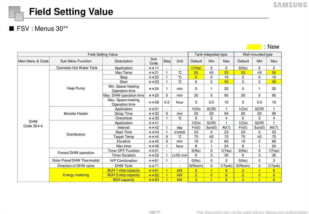
Field Setting Value■ FSV : Menus 30**
: New
Field Setting Value
Main Menu & Code
Sub Menu Function
Description
Domestic Hot Water Tank
Application
Max Temp
Stop
Start
Min. Space heating
Operation time
Max. DHW operation time
Max. Space heating
Operation time
Application
Delay Time
Overshoot
Application
Interval
Start Time
Target Temp
Duration
Max time
Timer OFF Function
Timer Duration
H/P Combination
DHW Tank
BUH 1 step capacity
BUH 2 step capacity
BSH capacity
Heat Pump
Booster Heater
DHW
Code 30✴✴
Disinfection
Forced DHW operation
Solar Panel/DHW Thermostat
Direction of DHW valve
Energy metering
Tank integrated type
Sub
Code
✴✴11
✴✴21
✴✴22
✴✴23
Wall-mounted type
Step
Unit
Default
Min
Max
Default
Min
Max
1
1
1
˚C
˚C
˚C
1(Yes)
55
0
5
0
45
0
5
2
55
10
30
0(No)
55
2
5
0
45
0
5
2
55
10
30
✴✴24
1
min
5
1
20
5
1
20
✴✴25
5
min
30
5
95
30
5
95
✴✴26
0.5
hour
3
0.5
10
3
0.5
10
✴✴31
✴✴32
✴✴33
✴✴41
✴✴42
✴✴43
✴✴44
✴✴45
✴✴46
✴✴51
✴✴52
✴✴61
✴✴71
✴✴81
✴✴82
✴✴83
5
1
1
1
5
5
1
1
1
1
1
1
106/77
1(On)
0(Off)
1
min
20
20
95
˚C
0
0
4
1(On)
0(Off)
1
day
Fri(5)
Sun(0) All(7)
o'clock
23
0
23
˚C
70
40
70
min
10
5
60
hour
8
1
24
0(No)
0
1(Yes)
(x10) min
6
3
30
0(No)
0
2
0(Room)
0
1(Tank)
kW
2
1
6
kW
2
0
6
kW
3
1
6
1(On)
20
0
1(On)
Fri(5)
23
70
10
8
0(No)
6
0(No)
0(Room)
2
2
3
0(Off)
1
20
95
0
4
0(Off)
1
Sun(0) All(7)
0
23
40
70
5
60
1
24
0
1(Yes)
3
30
0
2
0
1(Tank)
1
6
0
6
1
6
This Document can not be used without Samsung's authorization
107.
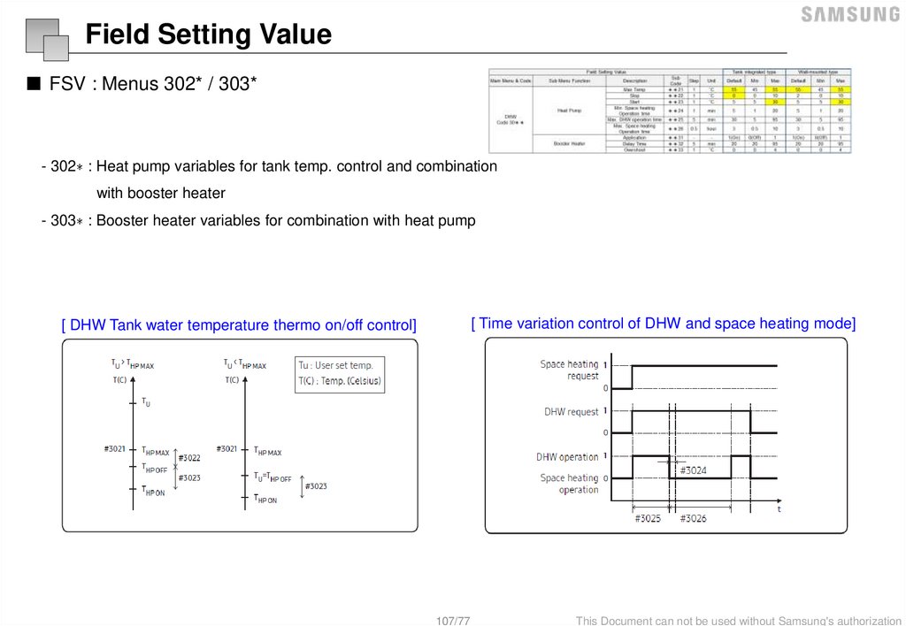
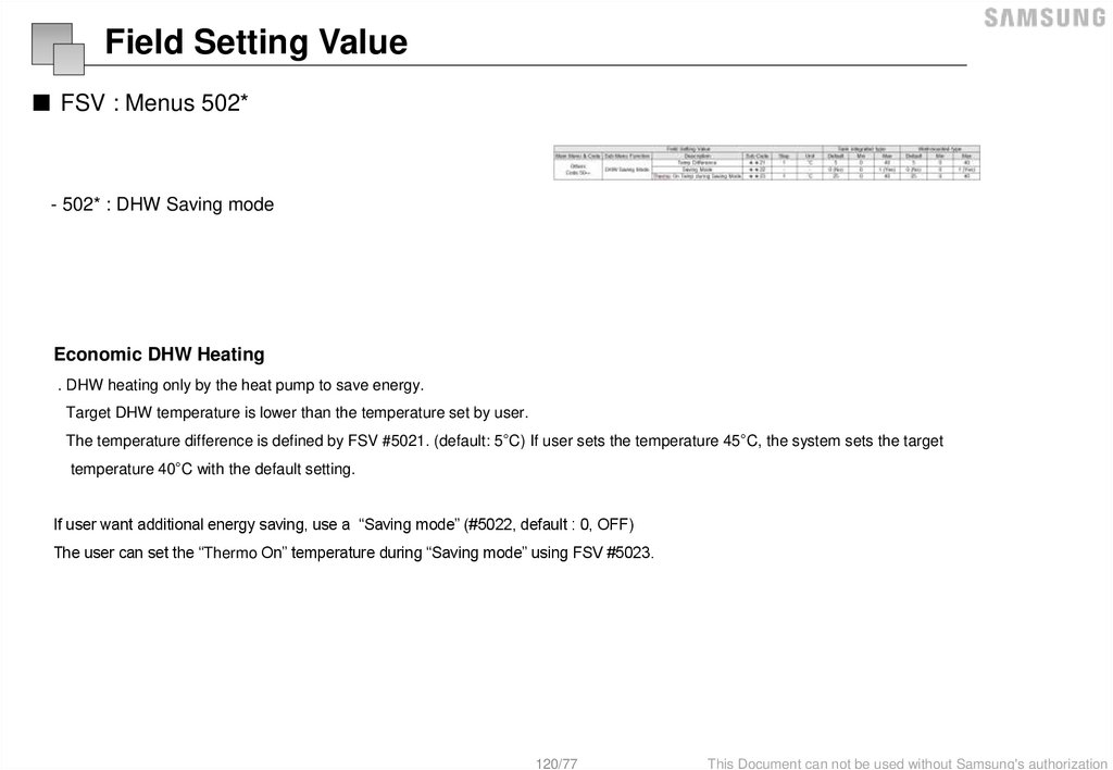
Field Setting Value■ FSV : Menus 302* / 303*
- 302∗ : Heat pump variables for tank temp. control and combination
with booster heater
- 303∗ : Booster heater variables for combination with heat pump
[ Time variation control of DHW and space heating mode]
[ DHW Tank water temperature thermo on/off control]
107/77
This Document can not be used without Samsung's authorization
108.
Field Setting Value■ FSV : Menus 302* / 303*
- 302∗ : Heat pump variables for tank temp. control and combination
with booster heater
- 303∗ : Booster heater variables for combination with heat pump
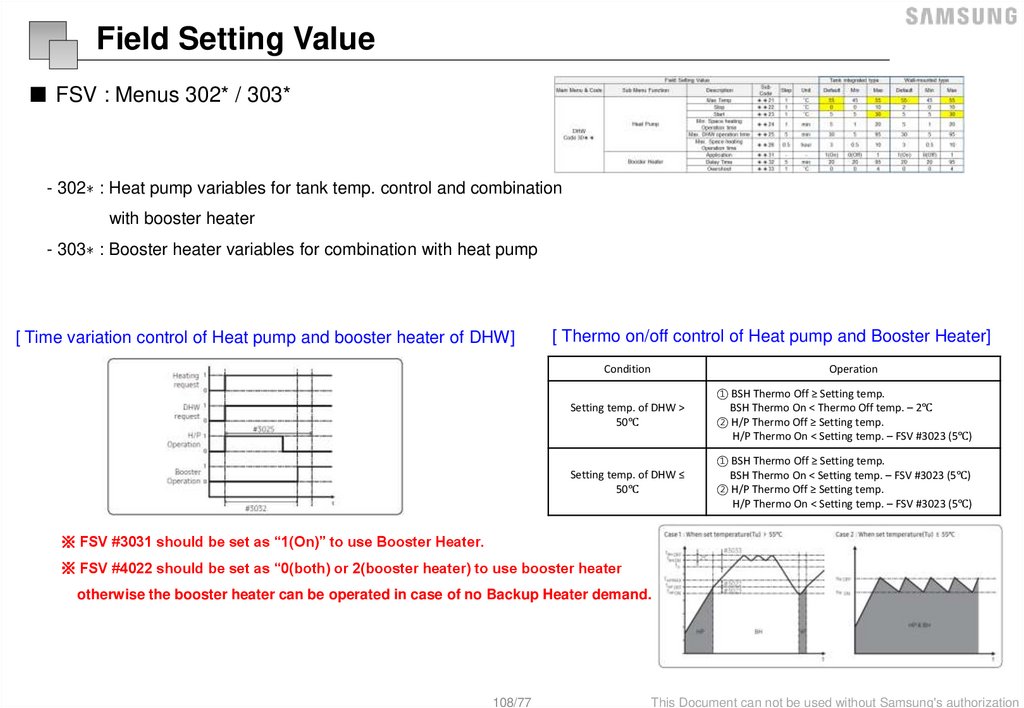
[ Time variation control of Heat pump and booster heater of DHW]
[ Thermo on/off control of Heat pump and Booster Heater]
Condition
Operation
Setting temp. of DHW >
50℃
① BSH Thermo Off ≥ Setting temp.
BSH Thermo On < Thermo Off temp. – 2℃
② H/P Thermo Off ≥ Setting temp.
H/P Thermo On < Setting temp. – FSV #3023 (5℃)
Setting temp. of DHW ≤
50℃
① BSH Thermo Off ≥ Setting temp.
BSH Thermo On < Setting temp. – FSV #3023 (5℃)
② H/P Thermo Off ≥ Setting temp.
H/P Thermo On < Setting temp. – FSV #3023 (5℃)
※ FSV #3031 should be set as “1(On)” to use Booster Heater.
※ FSV #4022 should be set as “0(both) or 2(booster heater) to use booster heater
otherwise the booster heater can be operated in case of no Backup Heater demand.
108/77
This Document can not be used without Samsung's authorization
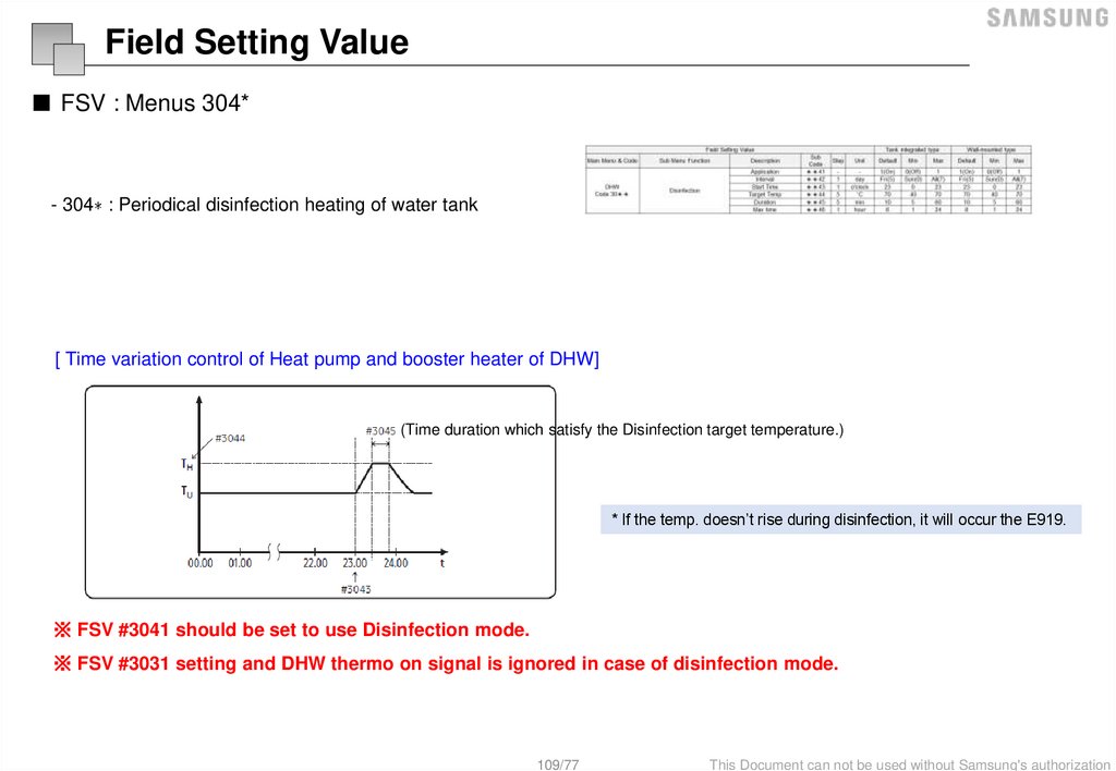
109.
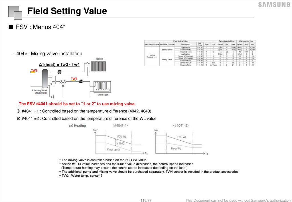
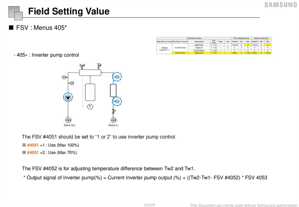
Field Setting Value■ FSV : Menus 304*
- 304∗ : Periodical disinfection heating of water tank
[ Time variation control of Heat pump and booster heater of DHW]
(Time duration which satisfy the Disinfection target temperature.)
* If the temp. doesn’t rise during disinfection, it will occur the E919.
※ FSV #3041 should be set to use Disinfection mode.
※ FSV #3031 setting and DHW thermo on signal is ignored in case of disinfection mode.
109/77
This Document can not be used without Samsung's authorization
110.
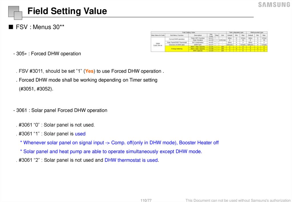
Field Setting Value■ FSV : Menus 30**
- 305∗ : Forced DHW operation
. FSV #3011, should be set ”1” (Yes) to use Forced DHW operation .
. Forced DHW mode shall be working depending on Timer setting
(#3051, #3052).
- 3061 : Solar panel Forced DHW operation
. #3061 “0” : Solar panel is not used.
. #3061 “1” : Solar panel is used
* Whenever solar panel on signal input -> Comp. off(only in DHW mode), Booster Heater off
* Solar panel and heat pump are able to operate simultaneously except DHW mode.
. #3061 “2” : Solar panel is not used and DHW thermostat is used.
110/77
This Document can not be used without Samsung's authorization
111.
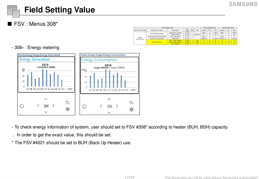
Field Setting Value■ FSV : Menus 308*
- 308∗ : Energy metering
- To check energy information of system, user should set to FSV #308* according to heater (BUH, BSH) capacity.
. In order to get the exact value, this should be set.
* The FSV #4021 should be set to BUH (Back Up Heater) use.
111/77
This Document can not be used without Samsung's authorization
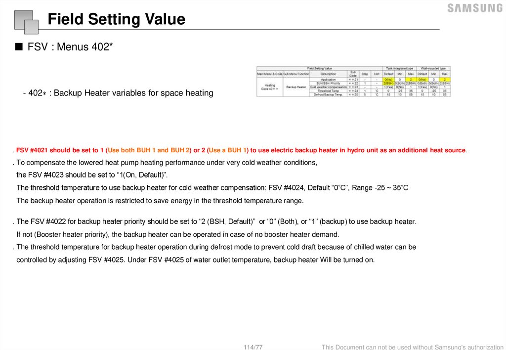
112.
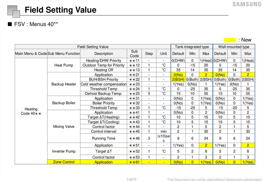
Field Setting Value■ FSV : Menus 40**
: New
Field Setting Value
Main Menu & Code Sub Menu Function
Heat Pump
Backup Heater
Backup Boiler
Heating
Code 40✴✴
Mixing Valve
Tank integrated type
Sub
Code
Heating/DHW Priority
✴✴11
Outdoor Temp for Priority ✴✴12
Heating Off
✴✴13
Application
✴✴21
BUH/BSH Priority
✴✴22
Cold weather compensation ✴✴23
Threshold Temp
✴✴24
Defrost Backup Temp.
✴✴25
Application
✴✴31
Boiler Priority
✴✴32
Threshold Temp
✴✴33
Application
✴✴41
Target ΔT(Heating)
✴✴42
Target ΔT(Cooling)
✴✴43
Control factor
✴✴44
Control interval
✴✴45
Description
Step
1
1
1
1
5
1
1
1
1
1
1
Unit
Default
Min
Max
Wall-mounted type
Default
Min
Max
0(DHW)
0
1(Heat) 0(DHW)
0
1(Heat)
˚C
0
-15
20
0
-15
20
˚C
35
14
35
35
14
35
0(No)
0
2
0(No)
0
2
2(BSH) 0(Both) 2(BSH) 0(Both) 0(Both) 2(BSH)
1(Yes) 0(No)
1
1(Yes) 0(No)
1
˚C
0
-25
35
0
-25
35
˚C
15
10
55
15
10
55
0(No)
0
1(Yes) 0(No)
0
1(Yes)
0(No)
0
1(Yes) 0(No)
0
1(Yes)
˚C
-15
-20
5
-15
-20
5
0(No)
0
2
0(No)
0
2
˚C
10
5
15
10
5
15
˚C
10
5
15
10
5
15
2
1
5
2
1
5
min
2
1
30
2
1
30
(x10)se
9
6
24
9
6
24
c
1(Yes)
0
2
1(Yes)
0
2
Running Time
✴✴46
3
Application
✴✴51
-
Inverter Pump
Target ΔT
✴✴52
1
˚C
5
2
8
5
2
8
Zone Control
Control factor
Application
✴✴53
✴✴61
1
-
-
2
0(No)
1
0
3
1(Yes)
2
0(No)
1
0
3
1(Yes)
112/77
This Document can not be used without Samsung's authorization
113.
Field Setting Value■ FSV : Menus 401*
- 401∗ : Heat pump variables for space heating
#3034 : Compensation temperature
FSV #4011 for DHW priority is set to “0(DHW)” (Default) as a default. Space heating gets a priority by setting FSV #4011 “1”,
but this is only valid when the outdoor temperature is lower than the specified temperature defined by FSV #4012.
113/77
This Document can not be used without Samsung's authorization
114.
Field Setting Value■ FSV : Menus 402*
- 402∗ : Backup Heater variables for space heating
. FSV #4021 should be set to 1 (Use both BUH 1 and BUH 2) or 2 (Use a BUH 1) to use electric backup heater in hydro unit as an additional heat source.
. To compensate the lowered heat pump heating performance under very cold weather conditions,
the FSV #4023 should be set to “1(On, Default)”.
The threshold temperature to use backup heater for cold weather compensation: FSV #4024, Default “0˚C”, Range -25 ~ 35˚C
The backup heater operation is restricted to save energy in the threshold temperature range.
. The FSV #4022 for backup heater priority should be set to “2 (BSH, Default)” or “0” (Both), or “1” (backup) to use backup heater.
If not (Booster heater priority), the backup heater can be operated in case of no booster heater demand.
. The threshold temperature for backup heater operation during defrost mode to prevent cold draft because of chilled water can be
controlled by adjusting FSV #4025. Under FSV #4025 of water outlet temperature, backup heater Will be turned on.
114/77
This Document can not be used without Samsung's authorization
115.
Field Setting Value■ FSV : Menus 403*
- 403∗ : External Backup Boiler for space heating
. FSV #4031 should be set to “1 (Yes)” to use a backup boiler as an additional heat source. (default: “0 (No installation)”)
. Priority of backup boiler and heat pump is defined by FSV #4032 (default: “0 (OFF)”)
. To compensate the lowered heat pump heating performance under very cold weather conditions, the backup boiler operates
instead of heat pump under the threshold temperature (FSV #4033, Default “-15˚C”, Range -20 ~ 5˚C).
115/77
This Document can not be used without Samsung's authorization
116.
Field Setting Value■ FSV : Menus 404*
- 404∗ : Mixing valve installation
ΔT(heat) = Tw3 - Tw4
TW3
TW4
. The FSV #4041 should be set to “1 or 2” to use mixing valve.
※ #4041 =1 : Controlled based on the temperature difference (4042, 4043)
※ #4041 =2 : Controlled based on the temperature difference of the WL value
•• The mixing valve is controlled based on the FCU WL value.
•• As the #4044 value increases and the #4045 value decreases, the control speed increases.
(Temperature hunting may occur if the control speed increases depending on the load.)
•• The additional pump and mixing valve should be purchased separately. TW4 sensor is included in the product accessories.
•• TW3 : Water temp. sensor 3
116/77
This Document can not be used without Samsung's authorization
117.
Field Setting Value■ FSV : Menus 405*
- 405∗ : Inverter pump control
The FSV #4051 should be set to “1 or 2” to use inverter pump control.
※ #4051 =1 : Use (Max 100%)
※ #4051 =2 : Use (Max 70%)
The FSV #4052 is for adjusting temperature difference between Tw2 and Tw1.
* Output signal of Inverter pump(%) = Current Inverter pump output (%) + ((Tw2-Tw1- FSV #4052) * FSV 4053
117/77
This Document can not be used without Samsung's authorization
118.
Field Setting Value■ FSV : Menus 4061
- 4061 : Zone control
The FSV #4061 should be set to “1(Yes)” to zone control.
118/77
This Document can not be used without Samsung's authorization
119.
Field Setting Value■ FSV : Menus 50**
: New
Field Setting Value
Description
Sub Code
Water Out Temp for Cooling
✴✴11
Room Temp for Cooling
✴✴12
Water Out Temp for Heating
✴✴13
Room Temp for Heating
✴✴14
Outing
Auto Cooling WL1 Temp
✴✴15
Auto Cooling WL2 Temp
✴✴16
Auto Heating WL1 Temp
✴✴17
Auto Heating WL2 Temp
✴✴18
Target Tank Temp
✴✴19
Temp Difference
✴✴21
Saving Mode
✴✴22
DHW Saving Mode
Thermo On Temp during Saving Mod
✴✴23
e
Application
✴✴41
Power Peak Control
Select forced off parts
✴✴42
Using input voltage
✴✴43
Frequency Ratio Control
✴✴51
Application
✴✴81
PV Control
Setting Temp Shift Value(Cooling)
✴✴82
Setting Temp Shift Value(Heating)
✴✴83
Application
✴✴91
Setting Temp Shift Value(Heating)
✴✴92
Smart Grid Control
Setting Temp Shift Value(DHW)
✴✴93
Main Menu & Code Sub Menu Function
Others
Code 50∗∗
DHW Mode
✴✴94
119/77
Tank integrated type
Default
Min
Max
25
5
25
30
18
30
15
15
55
16
16
30
25
5
25
25
5
25
15
15
55
15
15
55
30
30
70
5
0
40
0 (No)
0
1 (Yes)
Step
1
1
1
1
1
1
1
1
1
1
-
Unit
˚C
˚C
˚C
˚C
˚C
˚C
˚C
˚C
˚C
˚C
-
1
˚C
25
1
0.5
0.5
0.5
0.5
˚C
˚C
˚C
˚C
0 (No)
0 (All)
1 (High)
0 (No)
0 (No)
1
1
0 (No)
2
2
-
-
0
0
40
0
1 (Yes)
0
3
0 (Low)
1
0
1 (Yes)
0
1 (Yes)
0
5
0
5
0
1 (Yes)
2
5
2
5
0
1 (Power)
(Standard)
Wall-mounted type
Default
Min
Max
25
5
25
30
18
30
15
15
55
16
16
30
25
5
25
25
5
25
15
15
55
15
15
55
30
30
70
5
0
40
0 (No)
0
1 (Yes)
25
0 (No)
0 (All)
1 (High)
0 (No)
0 (No)
1
1
0 (No)
2
2
0
0
40
0
1 (Yes)
0
3
0 (Low)
1
0
1 (Yes)
0
1 (Yes)
0
5
0
5
0
1 (Yes)
2
5
2
5
0
1 (Power)
(Standard)
This Document can not be used without Samsung's authorization
120.
Field Setting Value■ FSV : Menus 502*
- 502* : DHW Saving mode
Economic DHW Heating
. DHW heating only by the heat pump to save energy.
Target DHW temperature is lower than the temperature set by user.
The temperature difference is defined by FSV #5021. (default: 5°C) If user sets the temperature 45°C, the system sets the target
temperature 40°C with the default setting.
If user want additional energy saving, use a “Saving mode” (#5022, default : 0, OFF)
The user can set the “Thermo On” temperature during “Saving mode” using FSV #5023.
120/77
This Document can not be used without Samsung's authorization
121.
Field Setting Value■ FSV : Menus 504*
- 504* : Power peak control
Peak Power Control (FSV 5041 = 1)
. If users make contracts with local electric power company for limiting the amount of power consumption when a surge in power
usage, users can set FSV of “Forced off”.
. And According to FSV (#5042), If input is “0 (default)”, Back up heater (BUH) is unavailable while external contact is high.
If input is “ 1”, Only Compressor(Heat Pump) is available.
If input is “ 2”, Only Booster Heater (BSH) is available.
If input is “3”, nothing is available.
. Applying the control when power voltage of input contact is high is default. According to FSV (#5043), it is available to adopt this
logic in low condition exceptionally.
. When applying to this logic, SAMSUNG controller come to get “Thermo off” condition for all operation.
121/77
This Document can not be used without Samsung's authorization
122.
Field Setting Value■ FSV : Menus 5051 (FR control)
※ ex) Normal
operation
-10℃ Max Hz : 90
0℃ Max Hz : 75
10℃ Max Hz : 60
※ ex) FR 100%
Control
-10℃ Max Hz : 60
0℃ Max Hz : 60
10℃ Max Hz : 60
※ ex) FR 80%
Control
-10℃ Max Hz : 48
0℃ Max Hz : 48
10℃ Max Hz : 48
Voltage (V)
FR
Hz
0.0 ≤ V≤ 1.0
50%
min
1.0 ≤ V≤ 2.0
60%
2.0 ≤ V≤ 3.0
70%
3.0 ≤ V≤ 4.0
80%
4.0 ≤ V≤ 5.0
90%
5.0 ≤ V≤ 6.0
100%
6.0 ≤ V≤ 7.0
110%
7.0 ≤ V≤ 8.0
120%
8.0 ≤ V≤ 8.5
130%
8.5 ≤ V≤ 9.0
140%
9.0 ≤ V≤ 10.0
150%
max
This is to limit the maximum frequency of the outdoor unit compressor. (if #5051 = 1 “use”)
External DC signal Control uses a DC voltage of 0 ~ 10V (0v = 50%, ~ 10v = 150%)
The minimum ~ maximum frequency section being divided with 11 steps of 10%
122/77
This Document can not be used without Samsung's authorization
123.
Field Setting Value■ FSV : Menus 508*
- 508* : PV Control (Photovoltaics control)
- This is for energy saving by using the solar energy.
- The FSV #5081 should be set to “1(Yes)” for PV control.
FSV
0
1
#5081 (New)
Disable (Default)
Activation
* Except for how water mode, This function is activated only for the outing mode.
Cooling mode (FSV #5082 = 2℃, Default)
① Room sensor setting : Current setting value - FSV #5082 (Min = FSV #1022)
② Water outlet setting : Current setting value - FSV #5082 (Min = FSV #1012)
③ Water law setting : Current setting value - FSV #5082 (Min = FSV #2061, #2062, #2071, #2072)
Heating mode (FSV #5083 = 2℃, Default)
① Room sensor setting : Current setting value + FSV #5083 (Max = FSV #1041)
② Water outlet setting : Current setting value + FSV #5083 (Max = FSV #1031)
③ Water law setting : Current setting value + FSV #5083 (Max = FSV #2021, #2022, #2031, #2032)
Hot water mode
- Forced thermo on regardless of outing mode : Setting temperature = Max temperature of hot water mode (FSV #1051)
123/77
This Document can not be used without Samsung's authorization
124.
Field Setting Value■ FSV : Menus 509*
- 509* : Smart Grid Control
- The FSV #5091 should be set to “1(Yes)” for PV control.
FSV
0
1
#5081 (New)
Disable (Default)
Activation
Operation mode for Smart Grid
1) Mode 1 : Forced thermo off of all system
Operation Mode
Terminal 1
Terminal 2
Mode 1
Short
Open
Mode 2
Open
Open
2) Mode 2 : Normal operation
Mode 3
Open
Short
→ Normal control is performed.
Mode 4
Short
Short
(normal determination of operation ON / OFF, Thermo ON / OFF)
124/77
This Document can not be used without Samsung's authorization
125.
Field Setting Value■ FSV : Menus 50**
3) Mode 3 : When operating on, the setting temperature is reflected as follows (FSV #5092 =2℃, #5093 = 5℃, Default)
→ The heating and hot water setting temperature are set by the FSV setting value.
① Heating mode (Room sensor setting) : Current setting value + FSV #5092 (Max = FSV #1041)
② Heating mode (Water outlet setting) : Current setting value + FSV #5092 (Max = FSV #1031)
③ Heating mode (Water law setting) : Current setting value + FSV #5092 (Max = FSV #2021, #2022, #2031, #2032)
④ How water mode : Current setting value + FSV #5093 (Max = FSV #1051)
4) Mdoe 4 : When operating on, the setting temperature is reflected as follows
Hot water mode
① #5094=0 : Normal operation (Heat pump is operated.) : Target setting temperature is 55℃.
② #5094=1 : Power/Forced hot water operation (Heat pump + Booster heater are operated.) : Target setting temperature is 70℃.
Heating mode
① Heating mode (Room sensor setting) : Current setting value + FSV #5092 + 3℃ (Max = FSV #1041)
② Heating mode (Water outlet setting) : Current setting value + FSV #5092 + 5℃ (Max = FSV #1031)
③ Heating mode (Water law setting) : Current setting value + FSV #5092 + 5℃ (Max = FSV #2021, #2022, #2031, #2032)
125/77
This Document can not be used without Samsung's authorization
126.
Special mode■ Self-Test mode
- Enter the self-test mode using wired remote controller,
* Load list : When pressing the corresponding button, you can set the load On or Off.
* Can set the load On or Off.
126/77
This Document can not be used without Samsung's authorization
127.
This Training Manual is a property of Samsung Electronics Co.,Ltd.Any unauthorized use of Manual can be punished under applicable International and/or domestic law.
[TM] VRF_DVM S_Installation_GL_EN_2016_Ver1.0