

Similar presentations:


Ahu connection kit
1.
AHU CONNECTION KIT2017.03
2.
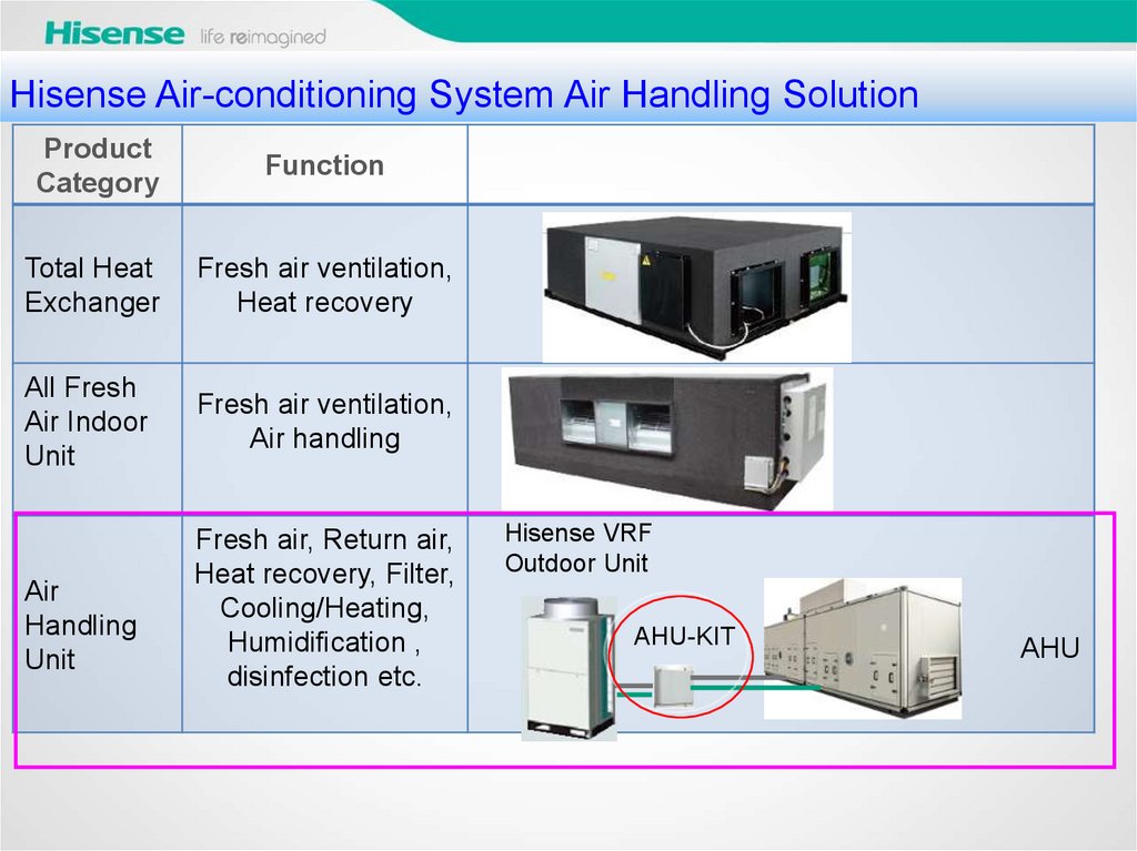
Hisense Air-conditioning System Air Handling SolutionProduct
Category
Function
Total Heat
Exchanger
Fresh air ventilation,
Heat recovery
All Fresh
Air Indoor
Unit
Fresh air ventilation,
Air handling
Air
Handling
Unit
Fresh air, Return air,
Heat recovery, Filter,
Cooling/Heating,
Humidification ,
disinfection etc.
Hisense VRF
Outdoor Unit
AHU-KIT
AHU
3.
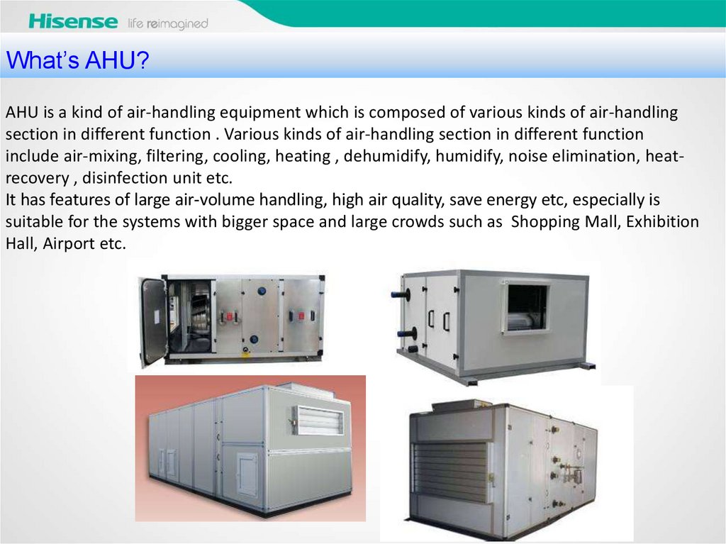
What’sAHU?
AHU 概念
AHU is a kind of air-handling equipment which is composed of various kinds of air-handling
section in different function . Various kinds of air-handling section in different function
include air-mixing, filtering, cooling, heating , dehumidify, humidify, noise elimination, heatrecovery , disinfection unit etc.
It has features of large air-volume handling, high air quality, save energy etc, especially is
suitable for the systems with bigger space and large crowds such as Shopping Mall, Exhibition
Hall, Airport etc.
4.
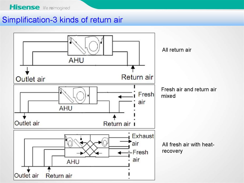
Simplification-3 kinds of return airAll return air
Fresh air and return air
mixed
All fresh air with heatrecovery
5.
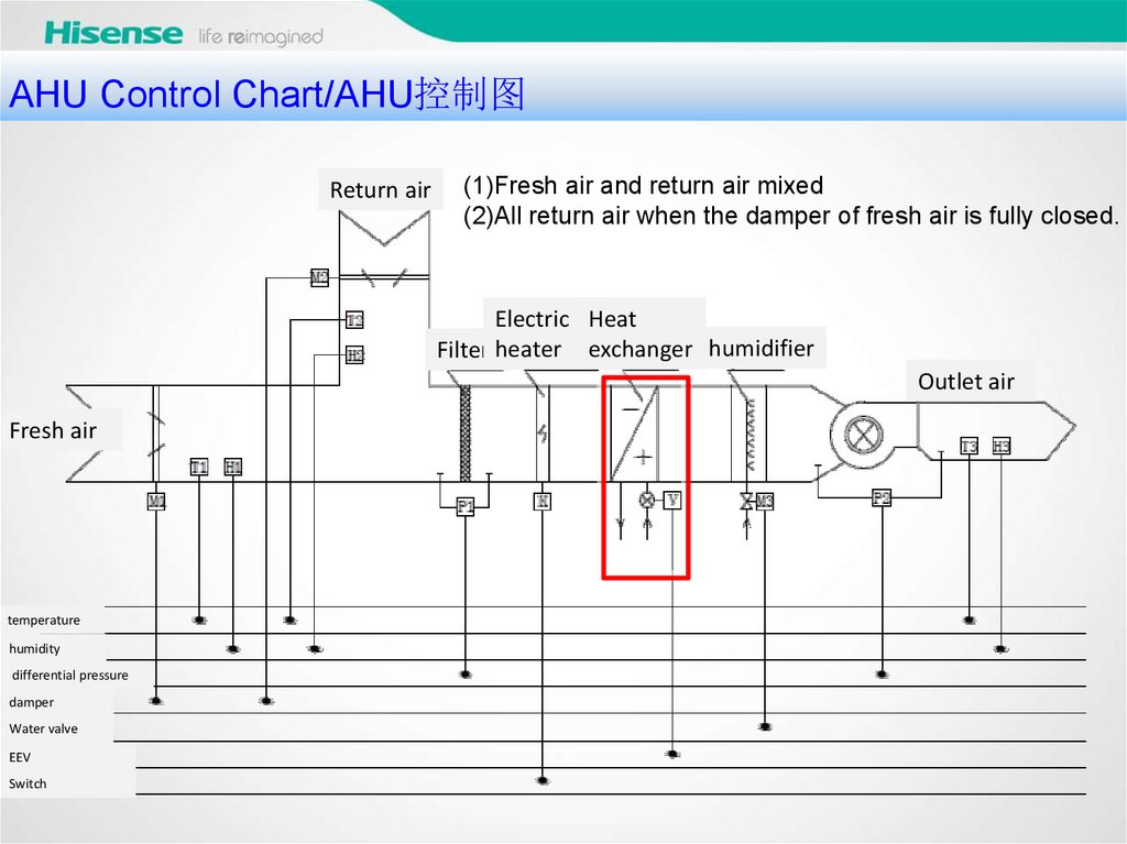
AHU Control Chart/AHU控制图Return air
(1)Fresh air and return air mixed
(2)All return air when the damper of fresh air is fully closed.
Electric Heat
Filter heater exchanger humidifier
Outlet air
Fresh air
temperature
humidity
differential pressure
damper
Water valve
EEV
Switch
6.
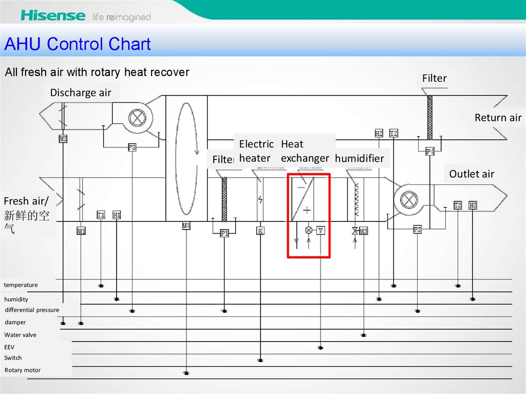
AHU Control ChartAll fresh air with rotary heat recover
Filter
Discharge air
Return air
Electric Heat
Filter heater exchanger humidifier
Outlet air
Fresh air/
新鲜的空
气
temperature
humidity
differential pressure
damper
Water valve
EEV
Switch
Rotary motor
7.
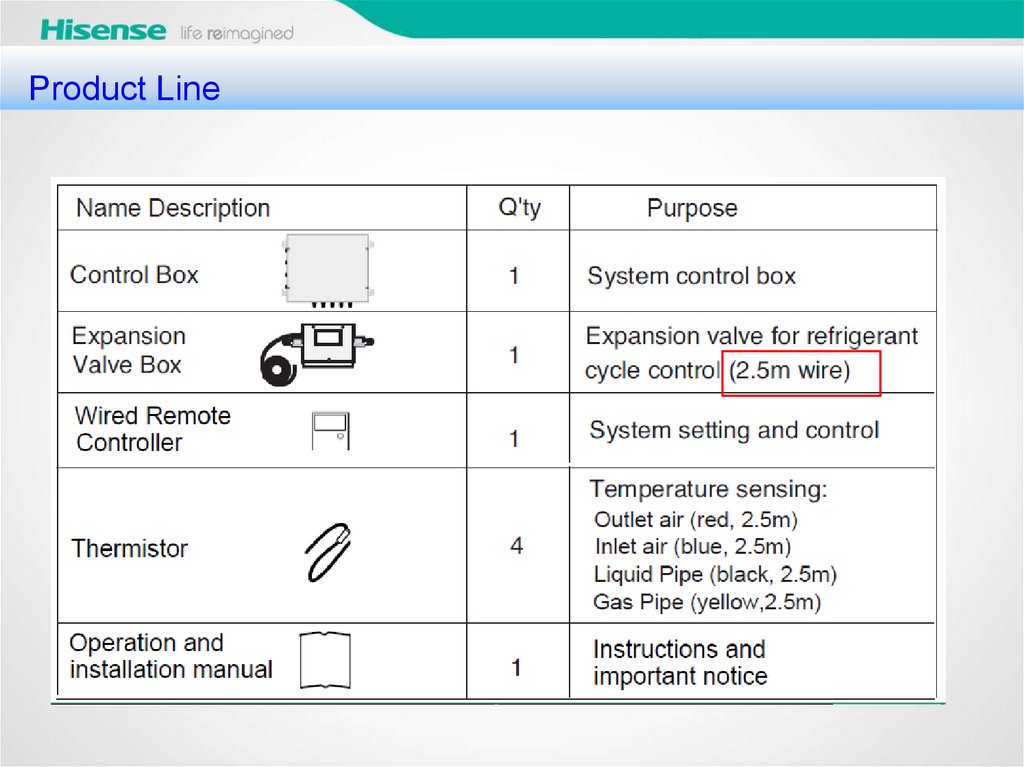
产品系列Product Line
8.
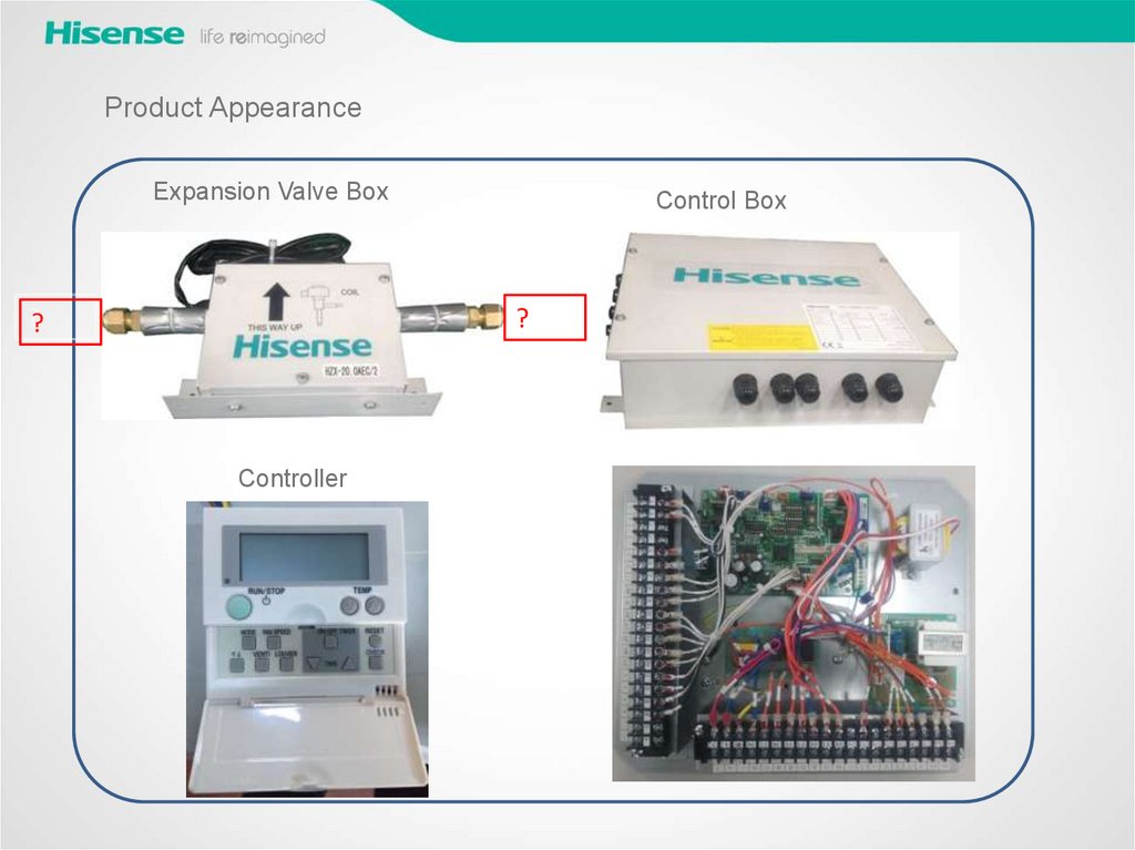
Product AppearanceExpansion Valve Box
Control Box
?
?
Controller
9.
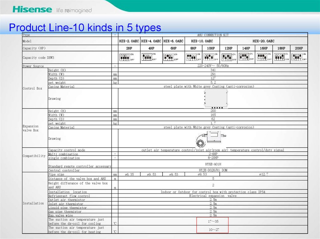
产品系列Product Line-10 kinds in 5 types
Type
-
Model
AHU CONNECTION KIT
HZX-2.0AEC HZX-4.0AEC HZX-6.0AEC
Capacity HP
2HP
4HP
6HP
HZX-10.0AEC
8HP
10HP
HZX-20.0AEC
12HP
14HP
16HP
18HP
Capacity code DSW3
Power Source
Control Box
220-240V 50/60Hz
341
291
127
5.2
steel plate with White grey Coating anti-corrosion
Height H
Width W
Depth D
net weight
Casing Material
mm
mm
kg
Drawing
Expansion
valve Box
Height H
Width W
Depth D
net weight
Casing Material
200
165
62
1.7
steel plate with White grey Coating anti-corrosion
mm
mm
mm
kg
Drawing
Capacity control mode
Compatibility Multi combination
single combination
Installation
Standard remote controller accessary
Central controller
Pipe size
Distance of the valve box and AHU
Height differance of the valve box
and AHU
Installation location
Refrigerant flow control
Outlet air thermistor
Inlet air thermistor
Liquid pipe thermistor
Gas pipe thermistor
Exp.valve wire
The suction air temperature just
before the dx-coil for cooling
The suction air temperature just
before the dx-coil for heating
-
outlet air temperature control/inlet air(room air) temperature control/duty signal
2-6HP
8-20HP
mm
m
HYJE-D02H/Hi DOM
ø9.53
5
HYXE-A01H
m
ø6.35
ø9.53
ø9.53
ø12.7
2
Indoor or Outdoor for control box with protection class IP54
Electrical expansion valve
2.5m
2.5m
2.5m
2.5m
2.5m
℃
℃
17 35
10 27
20HP
10.
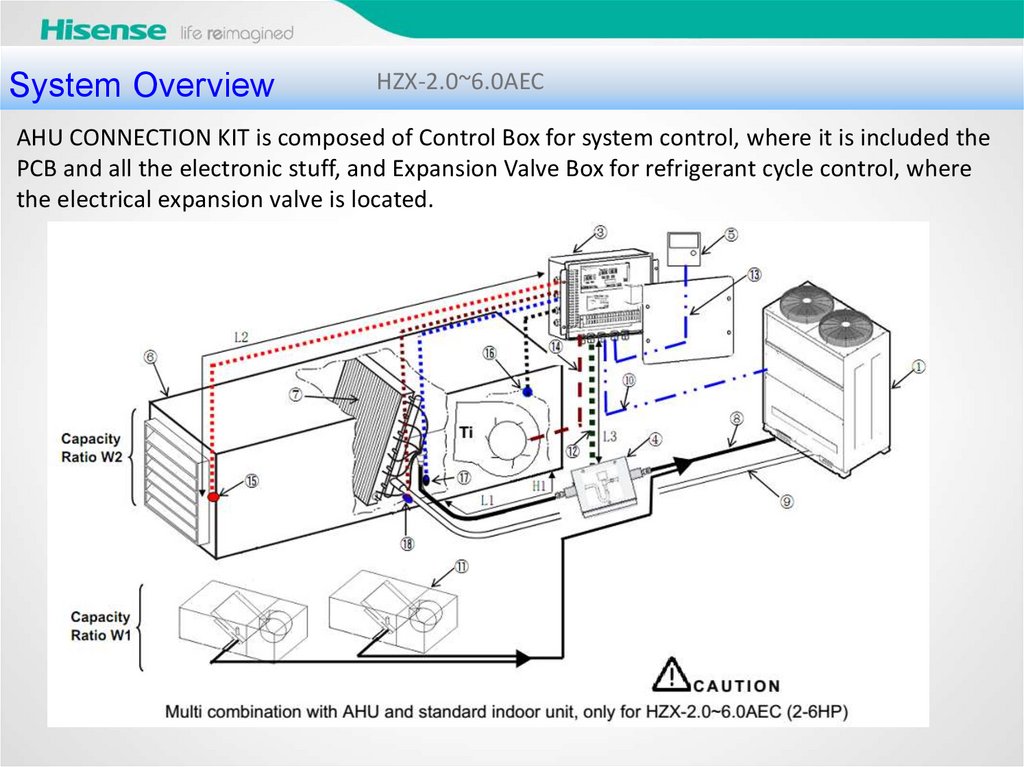
System OverviewHZX-2.0~6.0AEC
AHU CONNECTION KIT is composed of Control Box for system control, where it is included the
PCB and all the electronic stuff, and Expansion Valve Box for refrigerant cycle control, where
the electrical expansion valve is located.
11.
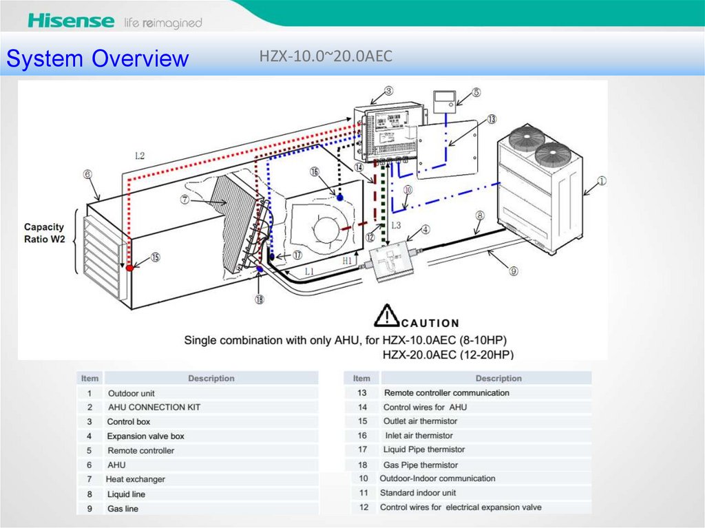
System OverviewHZX-10.0~20.0AEC
12.
回风/室温控制Capacity
Control Mode 1 Inlet air (room air) temperature control
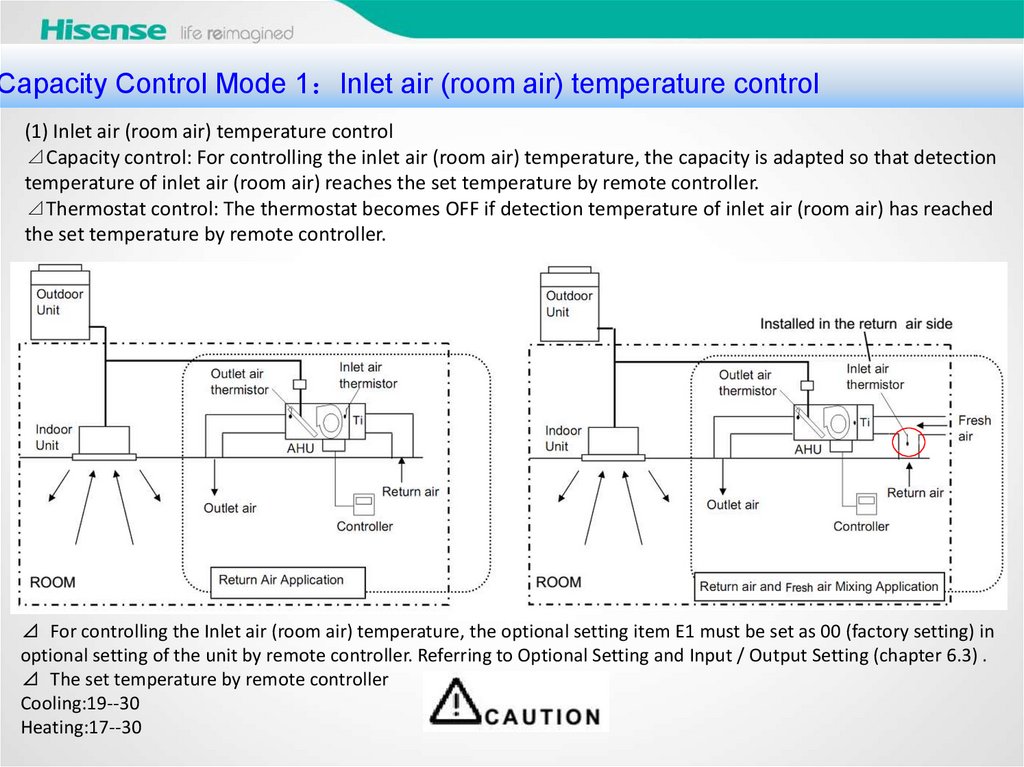
(1) Inlet air (room air) temperature control
⊿Capacity control: For controlling the inlet air (room air) temperature, the capacity is adapted so that detection
temperature of inlet air (room air) reaches the set temperature by remote controller.
⊿Thermostat control: The thermostat becomes OFF if detection temperature of inlet air (room air) has reached
the set temperature by remote controller.
⊿ For controlling the Inlet air (room air) temperature, the optional setting item E1 must be set as 00 (factory setting) in
optional setting of the unit by remote controller. Referring to Optional Setting and Input / Output Setting (chapter 6.3) .
⊿ The set temperature by remote controller
Cooling:19--30
Heating:17--30
13.
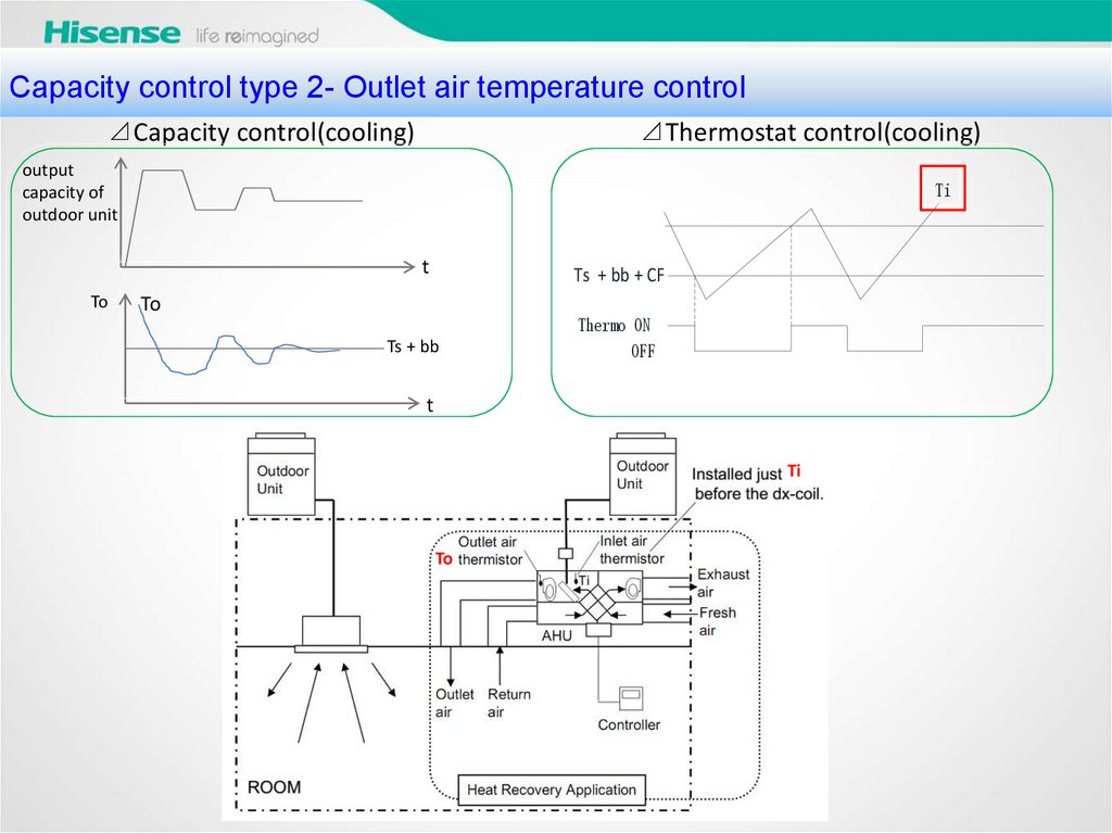
出风温度控制Capacity
control type 2- Outlet air temperature control
⊿Capacity control(cooling)
⊿Thermostat control(cooling)
output
capacity of
outdoor unit
Ti
t
To
Ts + bb + CF
To
Ts + bb
Thermo ON
OFF
t
Ti
To
14.
出风温度控制Capacity
control type 2- Outlet air temperature control
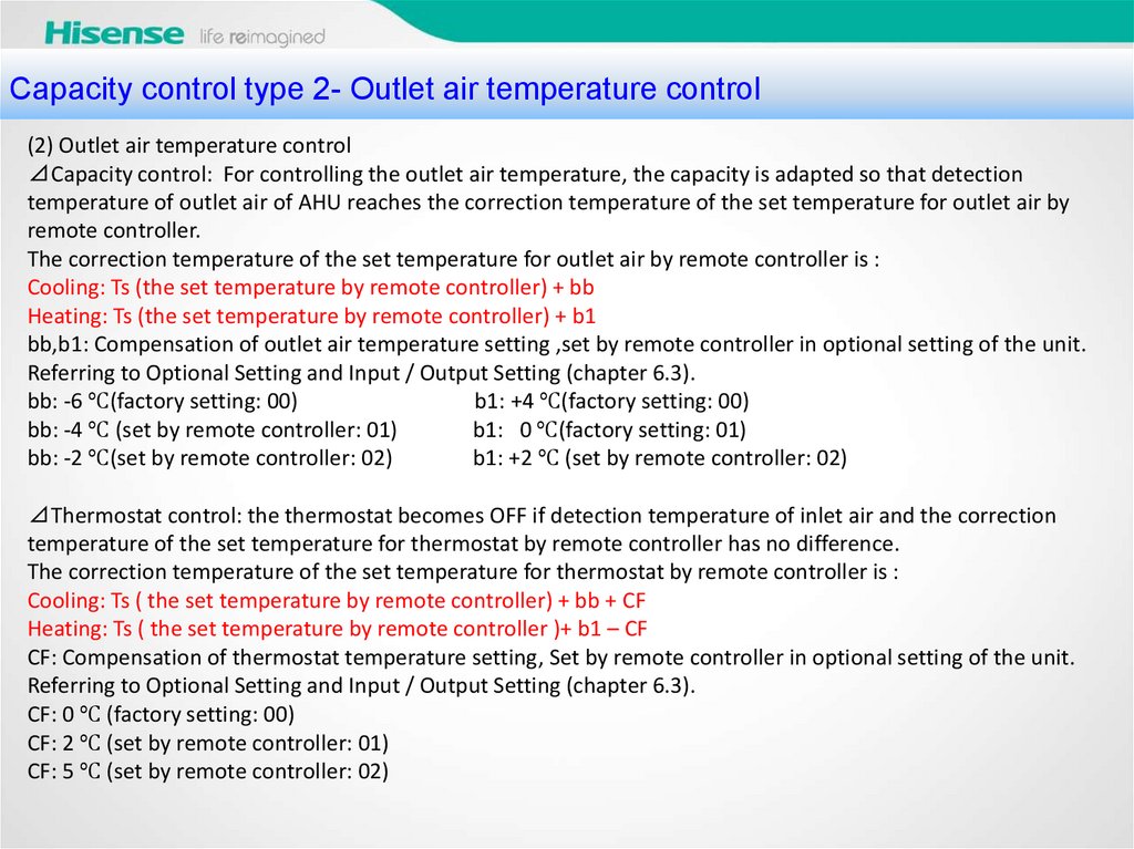
(2) Outlet air temperature control
⊿Capacity control: For controlling the outlet air temperature, the capacity is adapted so that detection
temperature of outlet air of AHU reaches the correction temperature of the set temperature for outlet air by
remote controller.
The correction temperature of the set temperature for outlet air by remote controller is :
Cooling: Ts (the set temperature by remote controller) + bb
Heating: Ts (the set temperature by remote controller) + b1
bb,b1: Compensation of outlet air temperature setting ,set by remote controller in optional setting of the unit.
Referring to Optional Setting and Input / Output Setting (chapter 6.3).
bb: -6 ℃(factory setting: 00)
b1: +4 ℃(factory setting: 00)
bb: -4 ℃ (set by remote controller: 01)
b1: 0 ℃(factory setting: 01)
bb: -2 ℃(set by remote controller: 02)
b1: +2 ℃ (set by remote controller: 02)
⊿Thermostat control: the thermostat becomes OFF if detection temperature of inlet air and the correction
temperature of the set temperature for thermostat by remote controller has no difference.
The correction temperature of the set temperature for thermostat by remote controller is :
Cooling: Ts ( the set temperature by remote controller) + bb + CF
Heating: Ts ( the set temperature by remote controller )+ b1 – CF
CF: Compensation of thermostat temperature setting, Set by remote controller in optional setting of the unit.
Referring to Optional Setting and Input / Output Setting (chapter 6.3).
CF: 0 ℃ (factory setting: 00)
CF: 2 ℃ (set by remote controller: 01)
CF: 5 ℃ (set by remote controller: 02)
15.
出风温度控制Capacity
control type 2- Outlet air temperature control
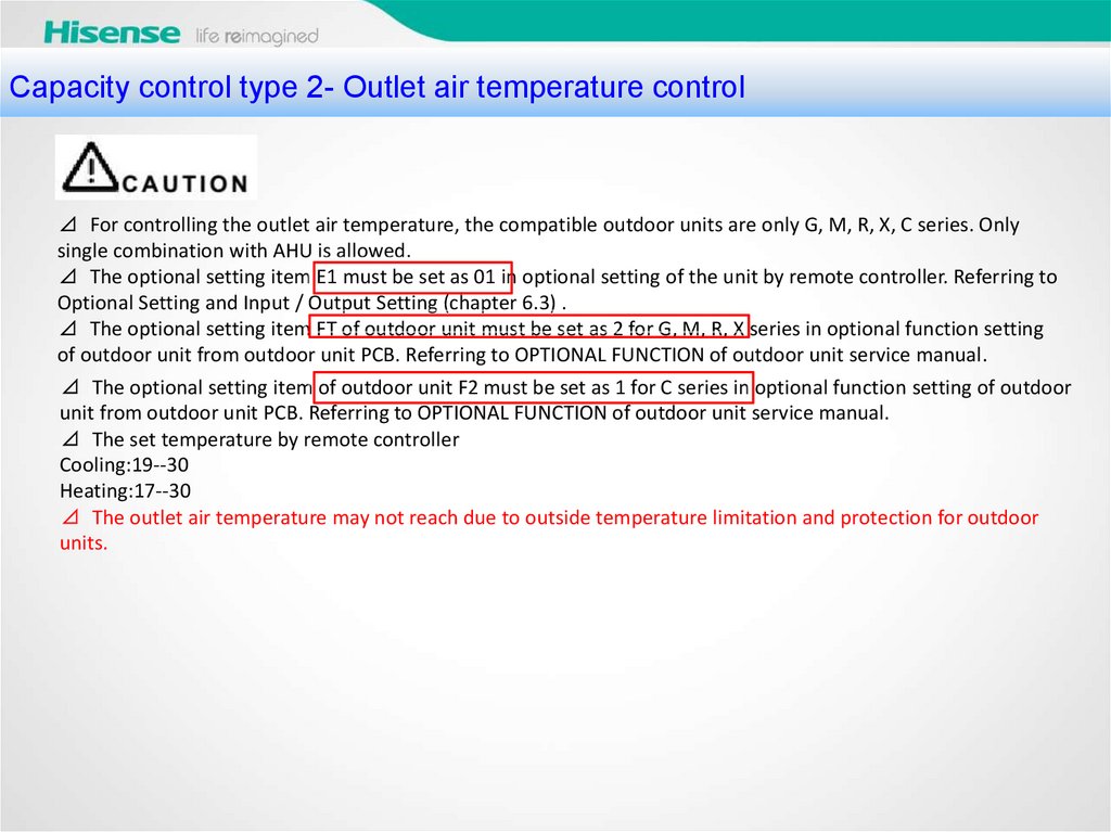
⊿ For controlling the outlet air temperature, the compatible outdoor units are only G, M, R, X, C series. Only
single combination with AHU is allowed.
⊿ The optional setting item E1 must be set as 01 in optional setting of the unit by remote controller. Referring to
Optional Setting and Input / Output Setting (chapter 6.3) .
⊿ The optional setting item FT of outdoor unit must be set as 2 for G, M, R, X series in optional function setting
of outdoor unit from outdoor unit PCB. Referring to OPTIONAL FUNCTION of outdoor unit service manual.
⊿ The optional setting item of outdoor unit F2 must be set as 1 for C series in optional function setting of outdoor
unit from outdoor unit PCB. Referring to OPTIONAL FUNCTION of outdoor unit service manual.
⊿ The set temperature by remote controller
Cooling:19--30
Heating:17--30
⊿ The outlet air temperature may not reach due to outside temperature limitation and protection for outdoor
units.
16.
电信号 0-10V/0-5V/4-20mA 预备Capacity
control type 3- Duty signal control
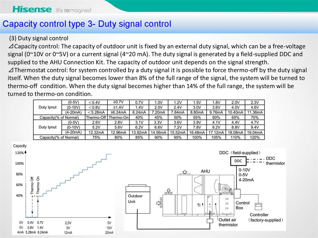
(3) Duty signal control
⊿Capacity control: The capacity of outdoor unit is fixed by an external duty signal, which can be a free-voltage
signal (0~10V or 0~5V) or a current signal (4~20 mA). The duty signal is generated by a field-supplied DDC and
supplied to the AHU Connection Kit. The capacity of outdoor unit depends on the signal strength.
⊿Thermostat control: for system controlled by a duty signal it is possible to force thermo-off by the duty signal
itself. When the duty signal becomes lower than 8% of the full range of the signal, the system will be turned to
thermo-off condition. When the duty signal becomes higher than 14% of the full range, the system will be
turned to thermo-on condition.
17.
电信号 0-10V/0-5V/4-20mA 预备Capacity
control type 3- Duty signal control
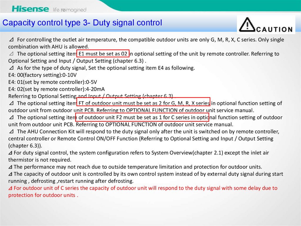
⊿ For controlling the outlet air temperature, the compatible outdoor units are only G, M, R, X, C series. Only single
combination with AHU is allowed.
⊿ The optional setting item E1 must be set as 02 in optional setting of the unit by remote controller. Referring to
Optional Setting and Input / Output Setting (chapter 6.3) .
⊿ As for the type of duty signal, Set the optional setting item E4 as following.
E4: 00(factory setting):0-10V
E4: 01(set by remote controller):0-5V
E4: 02(set by remote controller):4-20mA
Referring to Optional Setting and Input / Output Setting (chapter 6.3) .
⊿ The optional setting item FT of outdoor unit must be set as 2 for G, M, R, X series in optional function setting of
outdoor unit from outdoor unit PCB. Referring to OPTIONAL FUNCTION of outdoor unit service manual.
⊿ The optional setting item of outdoor unit F2 must be set as 1 for C series in optional function setting of outdoor
unit from outdoor unit PCB. Referring to OPTIONAL FUNCTION of outdoor unit service manual.
⊿ The AHU Connection Kit will respond to the duty signal only after the unit is switched on by remote controller,
central controller or Remote Control ON/OFF Function (Referring to Optional Setting and Input / Output Setting
(chapter 6.3)).
⊿ For duty signal control, the system configuration refers to System Overview(chapter 2.1) except the inlet air
thermistor is not required.
⊿ The performance may not reach due to outside temperature limitation and protection for outdoor units.
⊿ The capacity of outdoor unit is controlled by its own control system instead of by external duty signal during start
running , defrosting ,restart running after defrosting.
⊿ For outdoor unit of C series the capacity of outdoor unit will respond to the duty signal with some delay due to
protection for outdoor units .
18.
电信号 0-10V/0-5V/4-20mA 预备Capacity
control type - selection
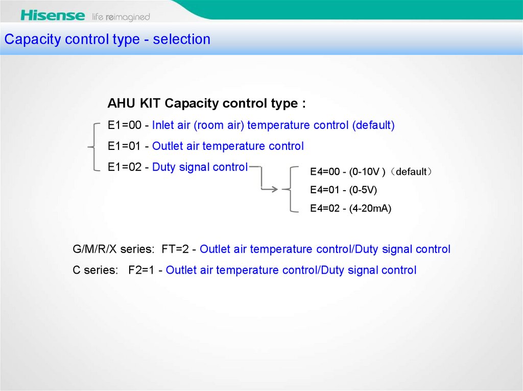
AHU KIT Capacity control type :
E1=00 - Inlet air (room air) temperature control (default)
E1=01 - Outlet air temperature control
E1=02 - Duty signal control
E4=00 - (0-10V ) default
E4=01 - (0-5V)
E4=02 - (4-20mA)
G/M/R/X series: FT=2 - Outlet air temperature control/Duty signal control
C series: F2=1 - Outlet air temperature control/Duty signal control
19.
Capacitycontrol type - FT=2 setting for G, M, R, X series
电信号 0-10V/0-5V/4-20mA 预备
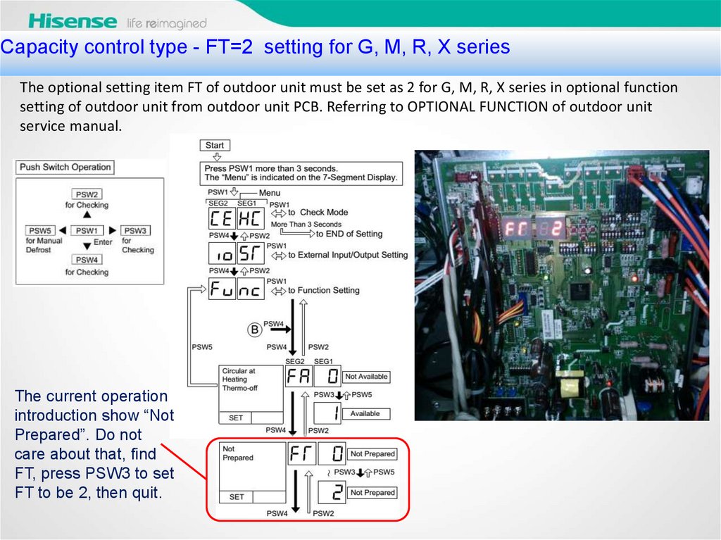
The optional setting item FT of outdoor unit must be set as 2 for G, M, R, X series in optional function
setting of outdoor unit from outdoor unit PCB. Referring to OPTIONAL FUNCTION of outdoor unit
service manual.
The current operation
introduction show “Not
Prepared”. Do not
care about that, find
FT, press PSW3 to set
FT to be 2, then quit.
20.
电信号 0-10V/0-5V/4-20mA 预备Capacity
control type - F2=1 setting for C series
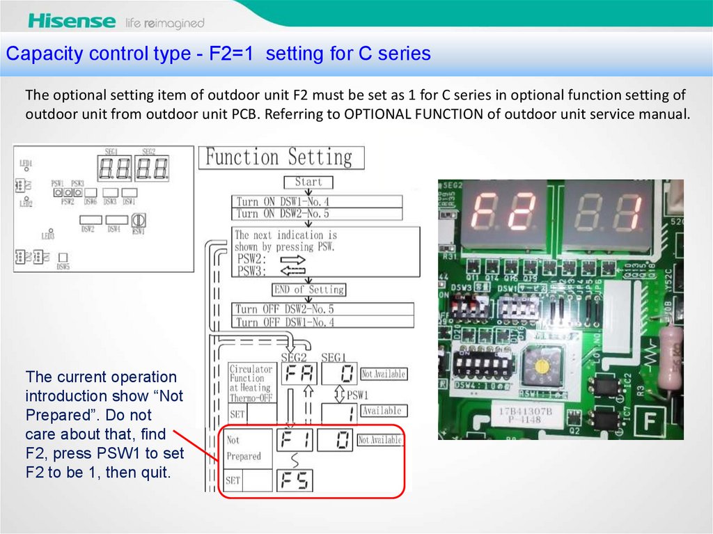
The optional setting item of outdoor unit F2 must be set as 1 for C series in optional function setting of
outdoor unit from outdoor unit PCB. Referring to OPTIONAL FUNCTION of outdoor unit service manual.
The current operation
introduction show “Not
Prepared”. Do not
care about that, find
F2, press PSW1 to set
F2 to be 1, then quit.
21.
Capacitycontrol type 3- Duty signal control The special introduction about C
电信号 0-10V/0-5V/4-20mA 预备
serial outdoor
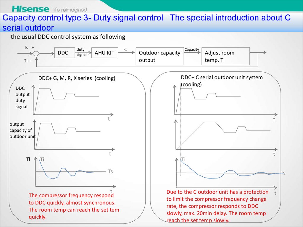
the usual DDC control system as following
Ts +
DDC
duty
signal
AHU KIT
Ti -
DDC+ G, M, R, X series (cooling)
DDC
output
duty
signal
Outdoor capacity
output
Capacity
t
t
Ti
Ti
Adjust room
temp. Ti
DDC+ C serial outdoor unit system
(cooling)
t
output
capacity of
outdoor unit
Ti
Kc
t
Ts
t
The compressor frequency respond
to DDC quickly, almost synchronous.
The room temp can reach the set tem
quickly.
Ts
Due to the C outdoor unit has a protection t
to limit the compressor frequency change
rate, the compressor responds to DDC
slowly, max. 20min delay. The room temp
reach the set temp slowly.
22.
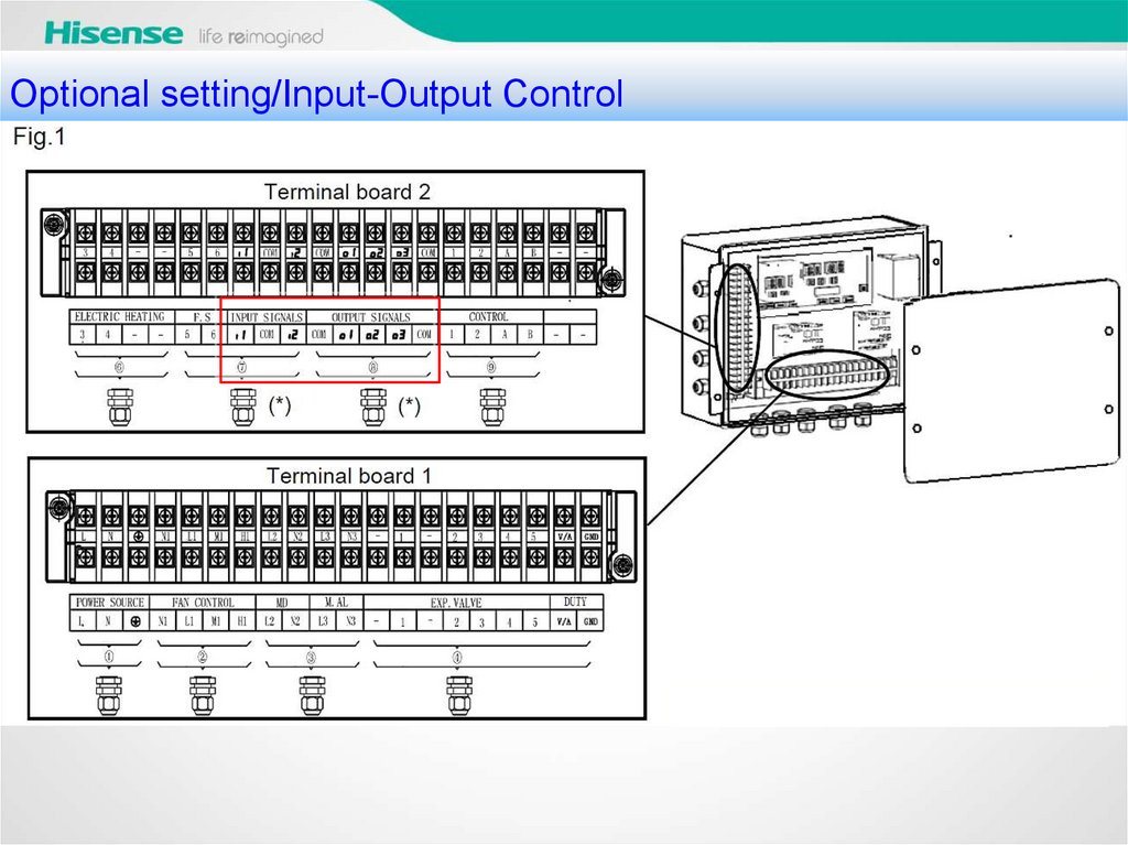
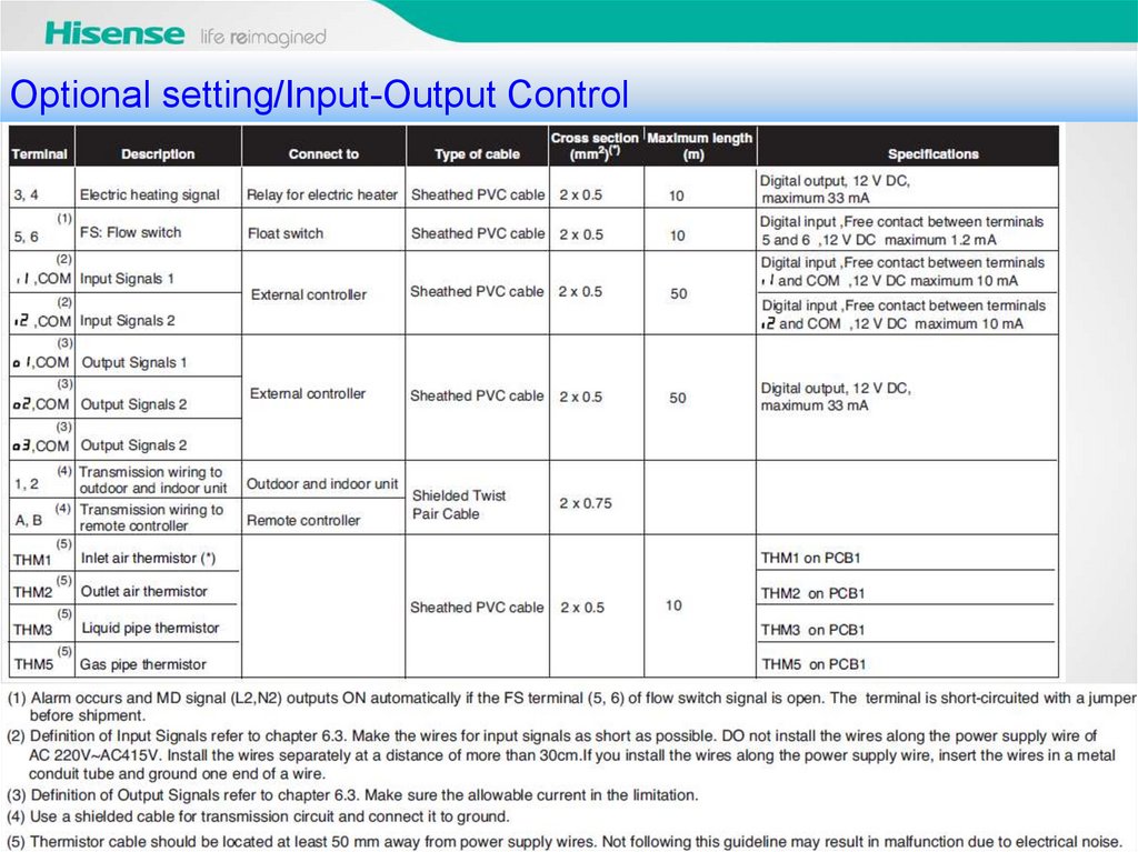
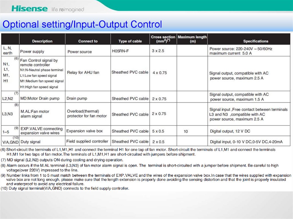
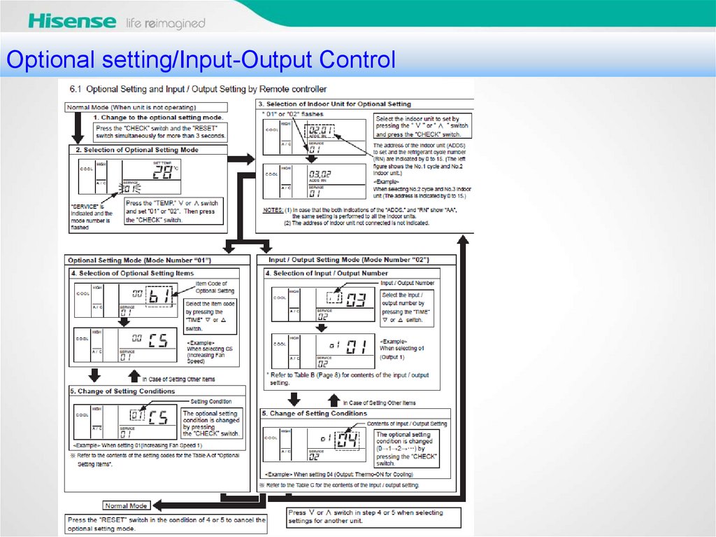
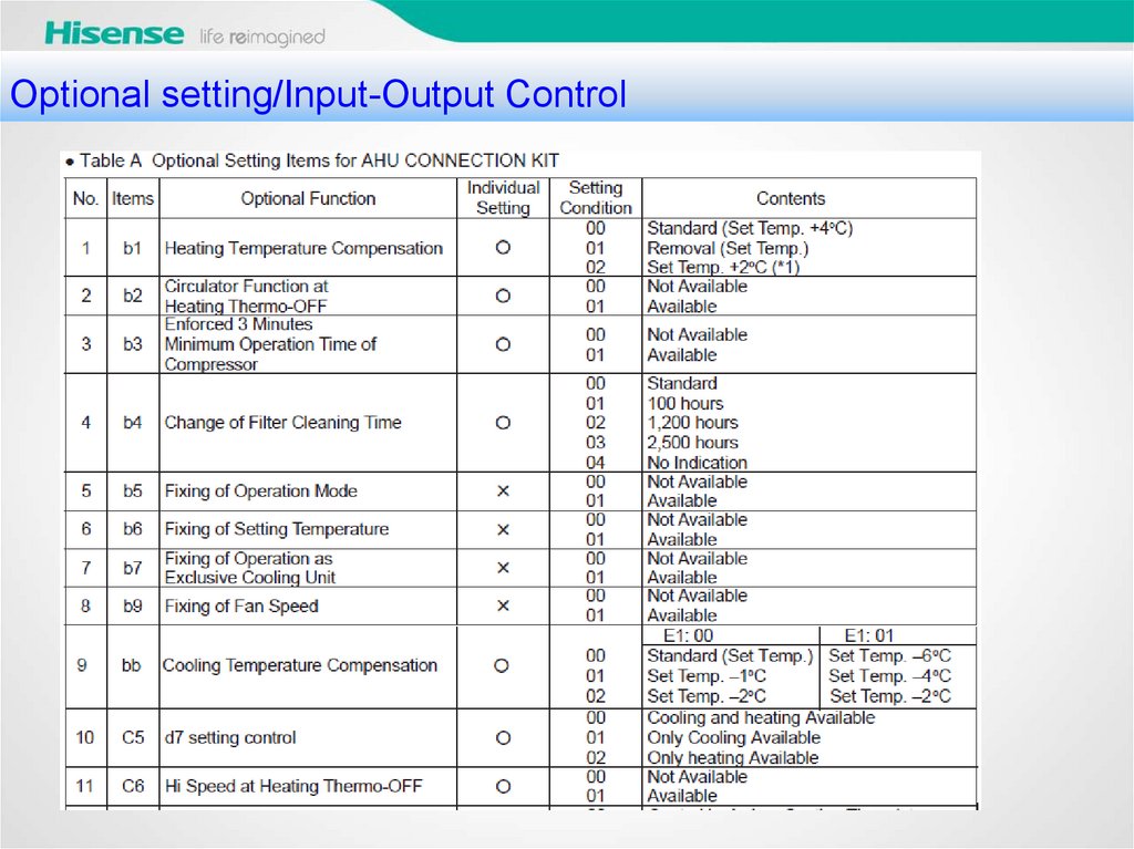
Optional setting/Input-Output Control23.
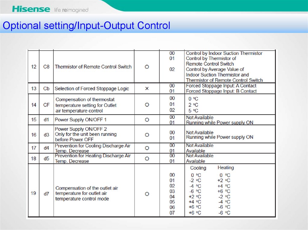
Optional setting/Input-Output Control24.
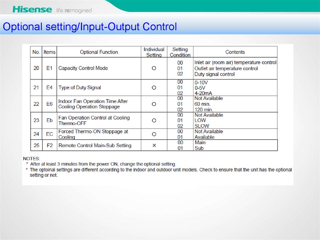
Optional setting/Input-Output Control25.
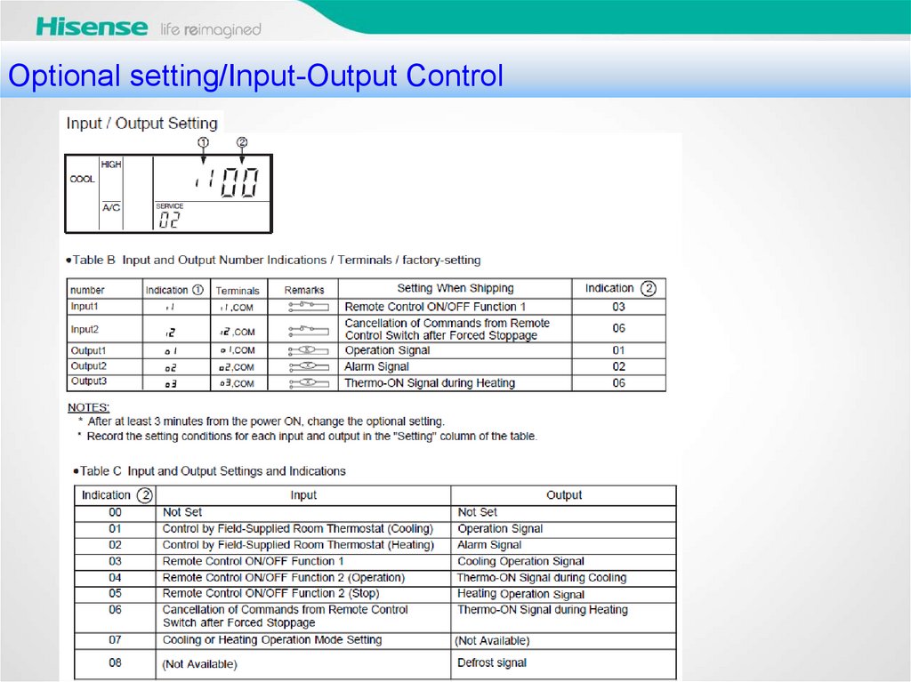
Optional setting/Input-Output Control26.
Optional setting/Input-Output Control27.
Optional setting/Input-Output Control28.
Optional setting/Input-Output Control29.
Optional setting/Input-Output Control30.
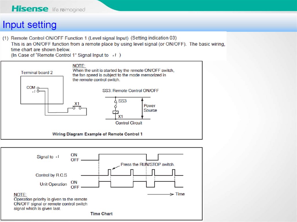
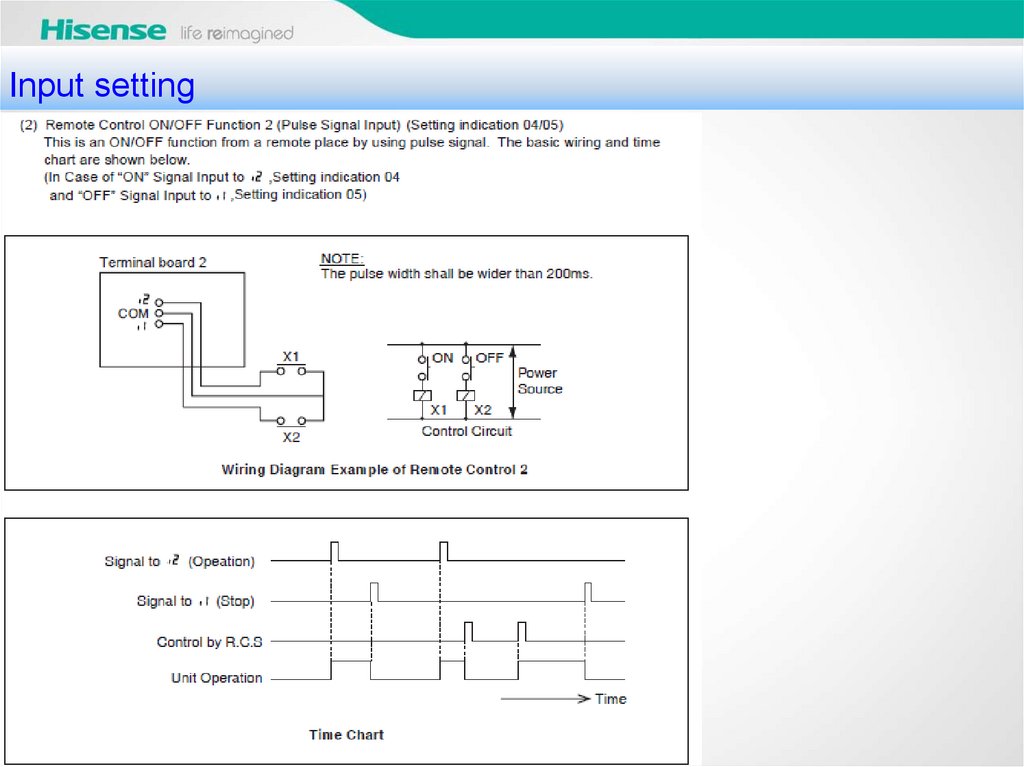
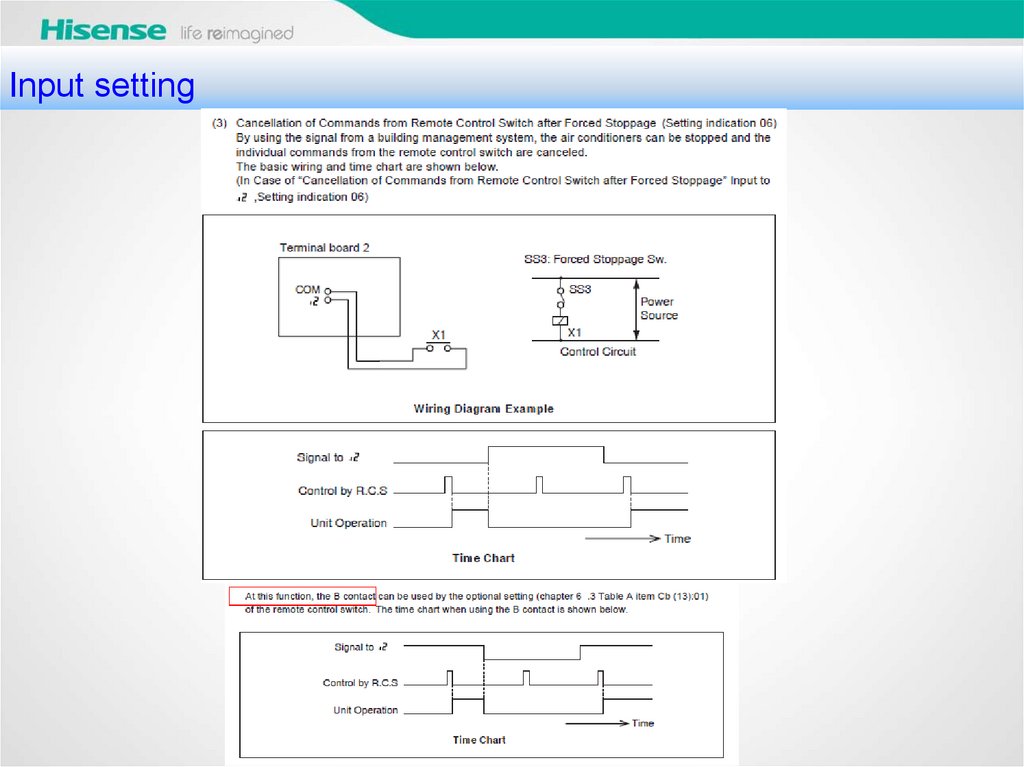
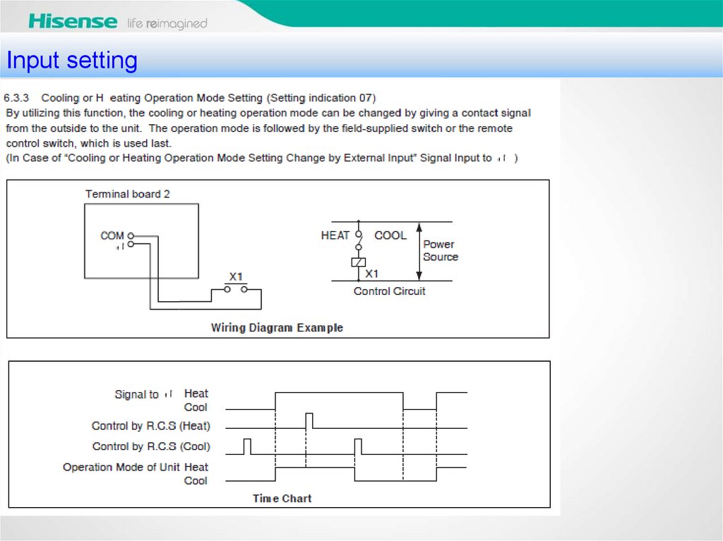
Input setting31.
Input setting32.
Input setting33.
Input setting34.
Input setting35.
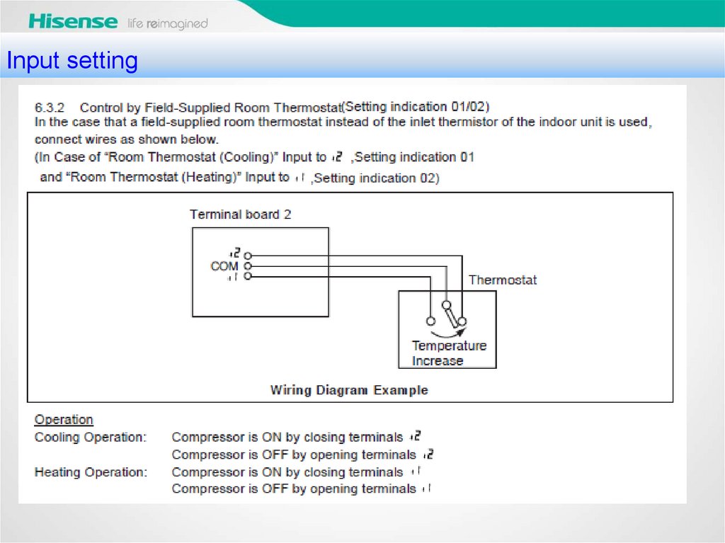
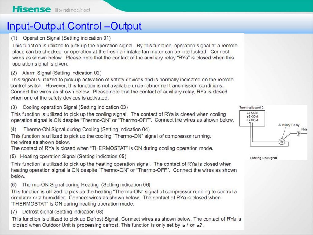
其他限制条件Input-Output
Control –Output
36.
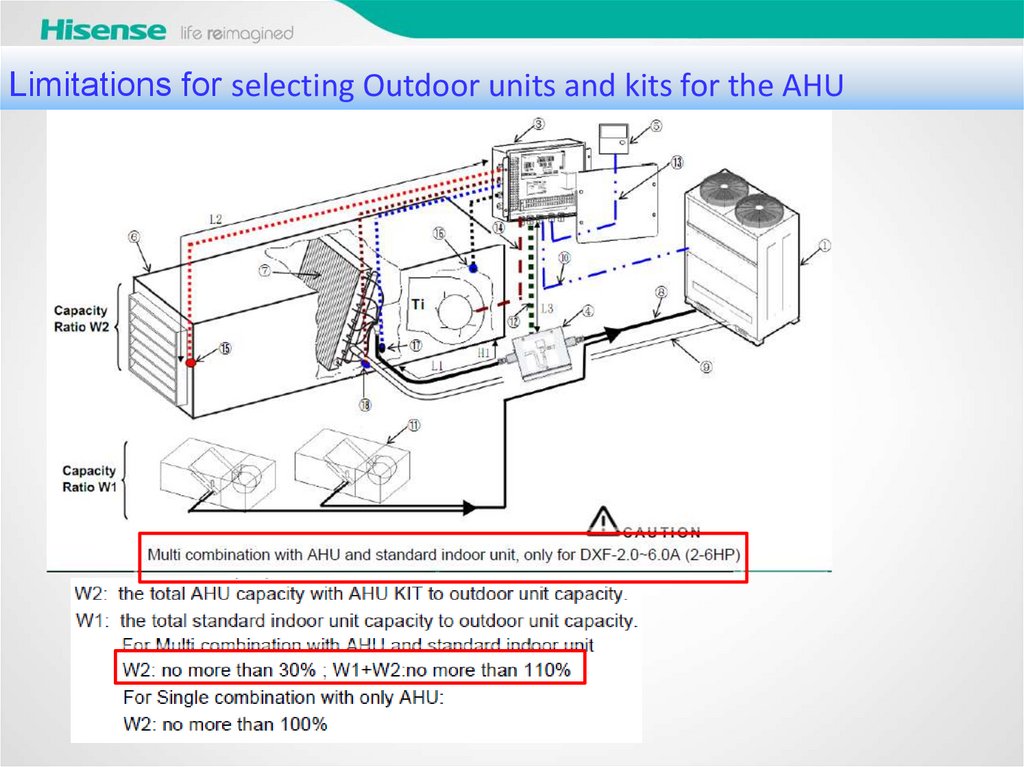
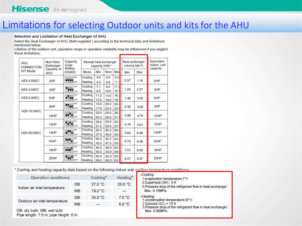
Limitations for selecting Outdoor units and kits for the AHU37.
Limitations for selecting Outdoor units and kits for the AHU38.
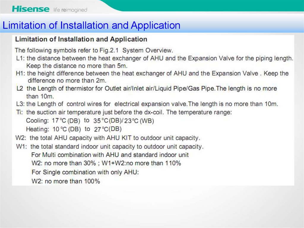
其他限制条件Limitation
of Installation and Application
39.
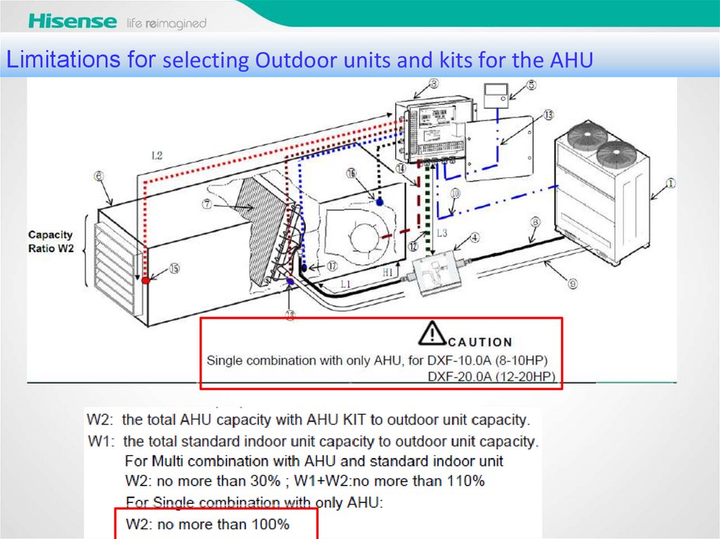
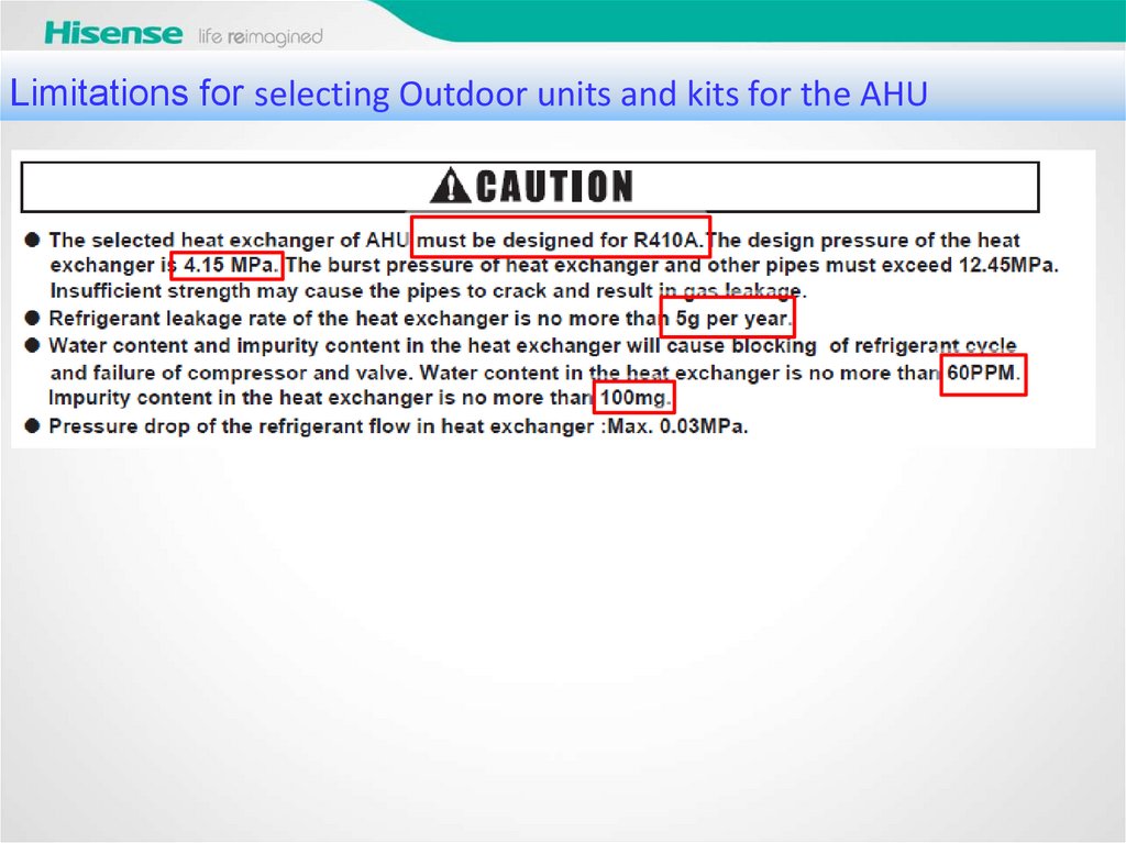
Limitations for selecting Outdoor units and kits for the AHU40.
Limitations for selecting Outdoor units and kits for the AHU41.
How should we select Outdoor units and kits for the AHUKITS excel
42.
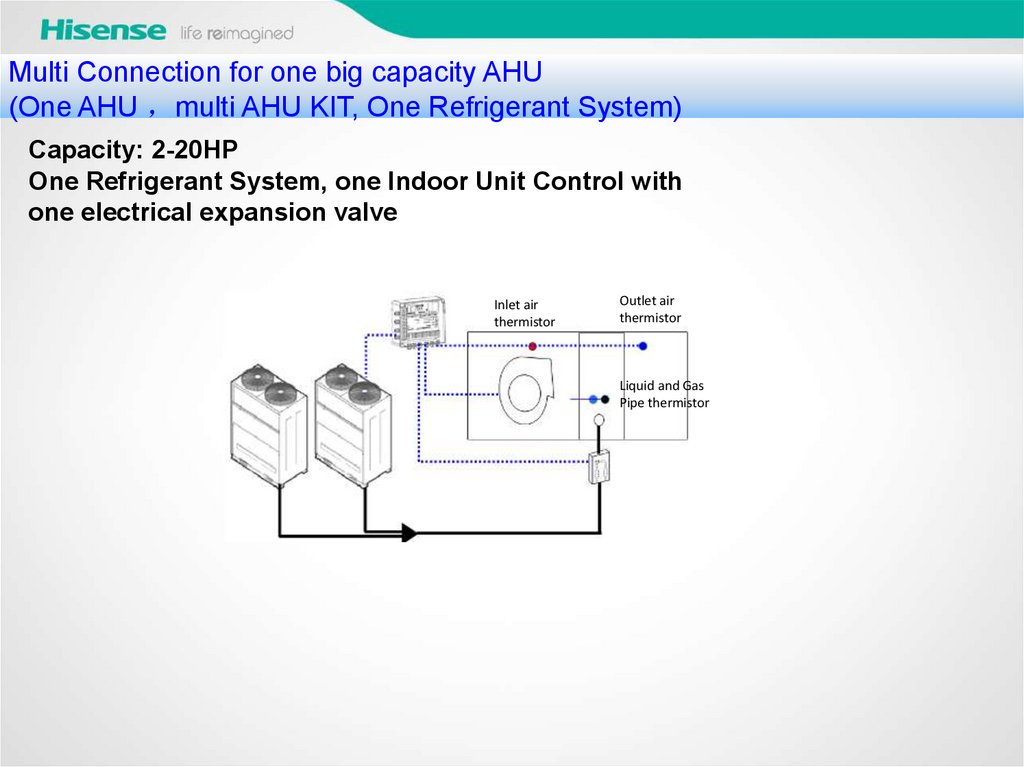
Multi Connection for one big capacity AHU(One AHU multi AHU KIT, One Refrigerant System)
Capacity: 2-20HP
One Refrigerant System, one Indoor Unit Control with
one electrical expansion valve
Inlet air
thermistor
Outlet air
thermistor
Liquid and Gas
Pipe thermistor
43.
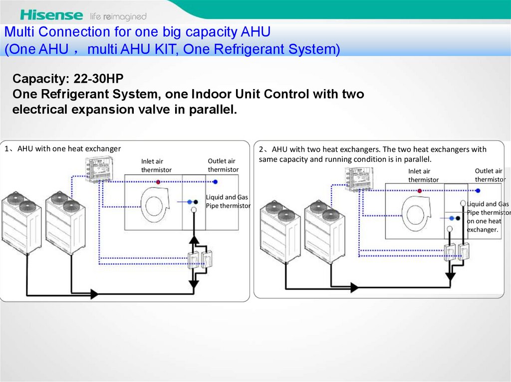
MultiConnection for one big capacity AHU
其他限制条件
(One AHU multi AHU KIT, One Refrigerant System)
Capacity: 22-30HP
One Refrigerant System, one Indoor Unit Control with two
electrical expansion valve in parallel.
1、AHU with one heat exchanger
Inlet air
thermistor
Outlet air
thermistor
Liquid and Gas
Pipe thermistor
2、AHU with two heat exchangers. The two heat exchangers with
same capacity and running condition is in parallel.
Inlet air
thermistor
Outlet air
thermistor
Liquid and Gas
Pipe thermistor
on one heat
exchanger.
44.
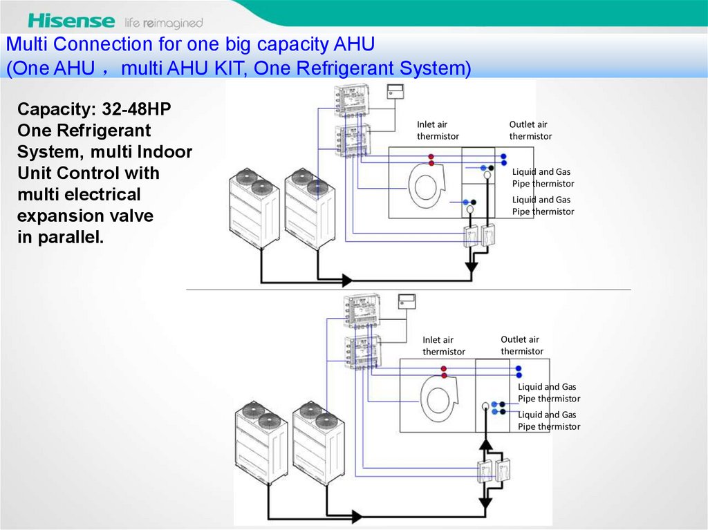
Multi Connection for one big capacity AHU(One AHU multi AHU KIT, One Refrigerant System)
Capacity: 32-48HP
One Refrigerant
System, multi Indoor
Unit Control with
multi electrical
expansion valve
in parallel.
Inlet air
thermistor
Outlet air
thermistor
Liquid and Gas
Pipe thermistor
Liquid and Gas
Pipe thermistor
Inlet air
thermistor
Outlet air
thermistor
Liquid and Gas
Pipe thermistor
Liquid and Gas
Pipe thermistor
45.
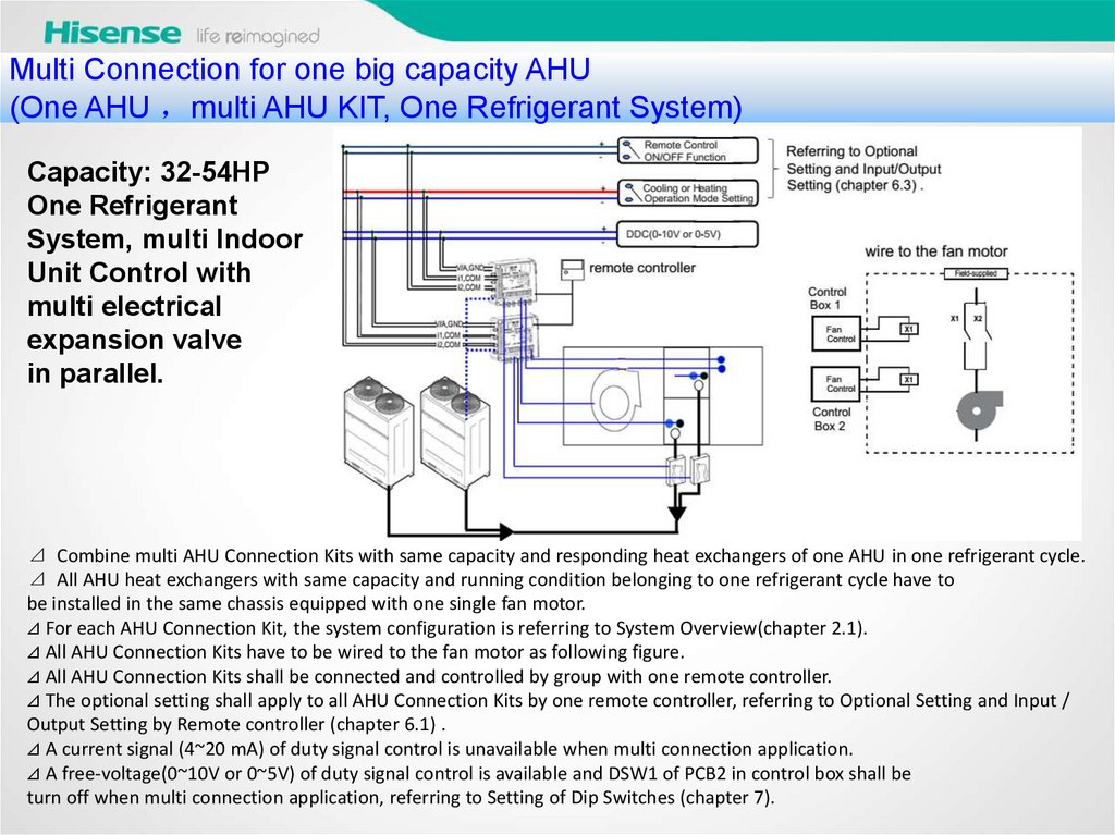
Multi Connection for one big capacity AHU(One AHU multi AHU KIT, One Refrigerant System)
Capacity: 32-54HP
One Refrigerant
System, multi Indoor
Unit Control with
multi electrical
expansion valve
in parallel.
⊿ Combine multi AHU Connection Kits with same capacity and responding heat exchangers of one AHU in one refrigerant cycle.
⊿ All AHU heat exchangers with same capacity and running condition belonging to one refrigerant cycle have to
be installed in the same chassis equipped with one single fan motor.
⊿ For each AHU Connection Kit, the system configuration is referring to System Overview(chapter 2.1).
⊿ All AHU Connection Kits have to be wired to the fan motor as following figure.
⊿ All AHU Connection Kits shall be connected and controlled by group with one remote controller.
⊿ The optional setting shall apply to all AHU Connection Kits by one remote controller, referring to Optional Setting and Input /
Output Setting by Remote controller (chapter 6.1) .
⊿ A current signal (4~20 mA) of duty signal control is unavailable when multi connection application.
⊿ A free-voltage(0~10V or 0~5V) of duty signal control is available and DSW1 of PCB2 in control box shall be
turn off when multi connection application, referring to Setting of Dip Switches (chapter 7).
46.
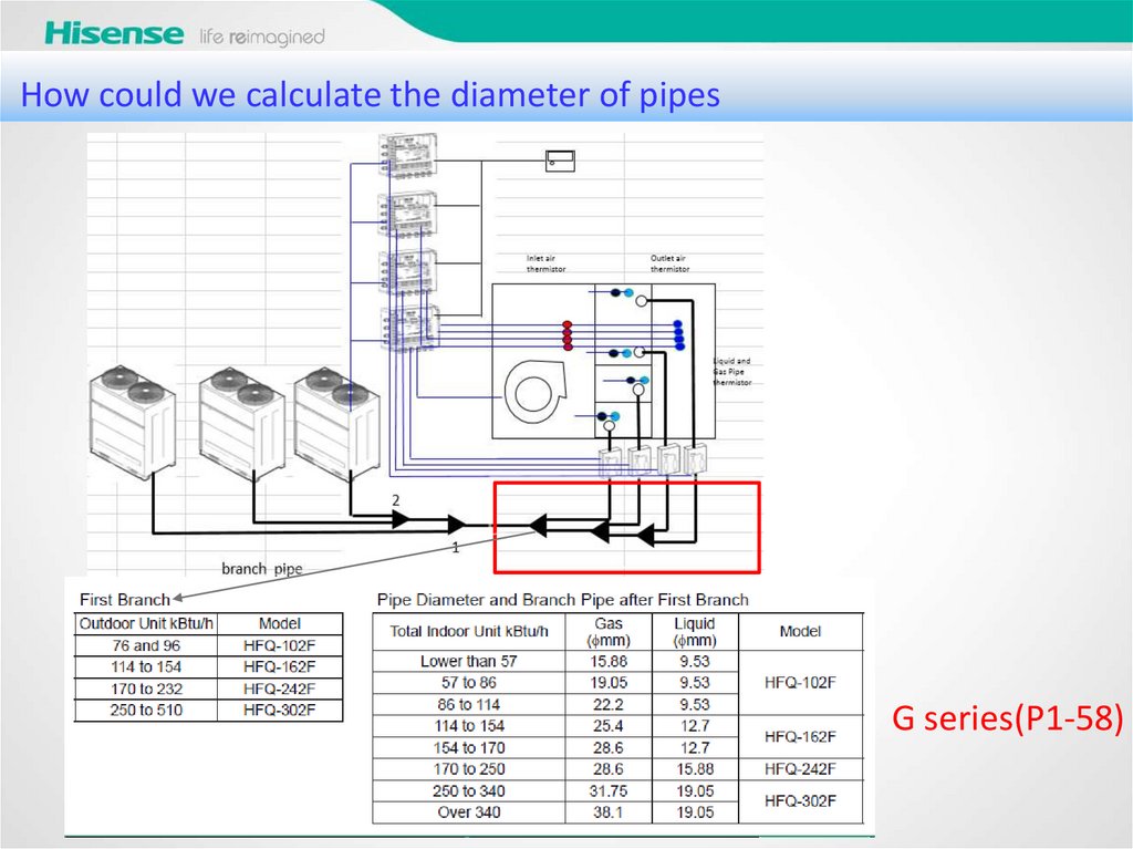
How could we calculate the diameter of pipesG series(P1-58)
47.
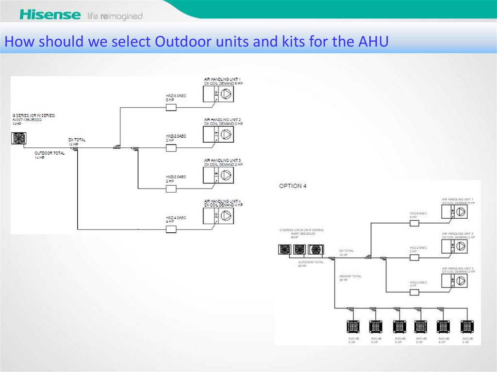
How should we select Outdoor units and kits for the AHU48.
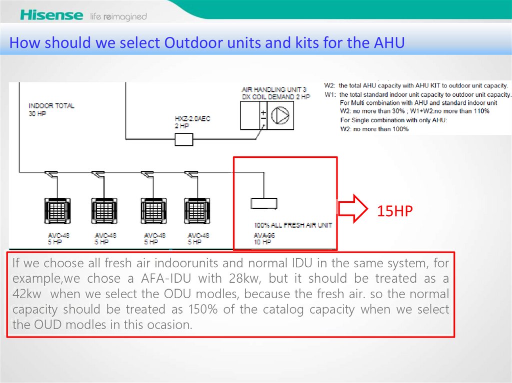
How should we select Outdoor units and kits for the AHU15HP
If we choose all fresh air indoorunits and normal IDU in the same system, for
example,we chose a AFA-IDU with 28kw, but it should be treated as a
42kw when we select the ODU modles, because the fresh air. so the normal
capacity should be treated as 150% of the catalog capacity when we select
the OUD modles in this ocasion.
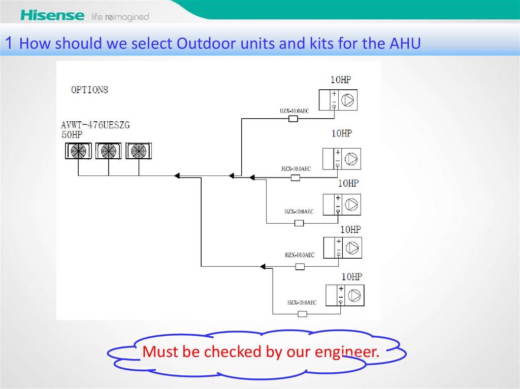
49.
1 How should we select Outdoor units and kits for the AHUMust be checked by our engineer.