

 industry
Similar presentations:


A600 Everything for a perfect coffee. Training
1.
Aarburg, 13/10/20Training
A600
1
© Franke, www.franke.com
2.
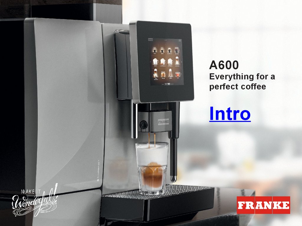
A600Everything for a
perfect coffee
Intro
2
© Franke, www.franke.com
3.
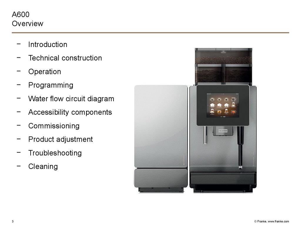
A600Overview
− Introduction
− Technical construction
− Operation
− Programming
− Water flow circuit diagram
− Accessibility components
− Commissioning
− Product adjustment
− Troubleshooting
− Cleaning
3
© Franke, www.franke.com
4.
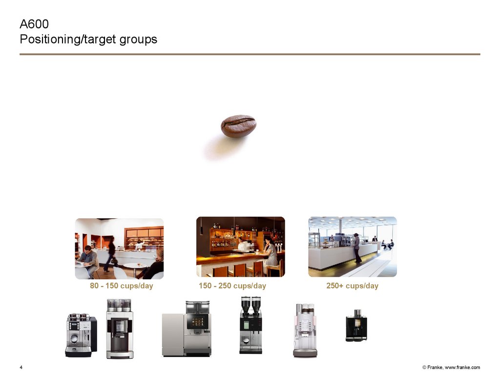
A600Positioning/target groups
80 - 150 cups/day
4
150 - 250 cups/day
250+ cups/day
© Franke, www.franke.com
5.
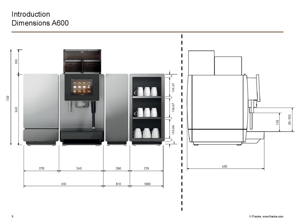
IntroductionDimensions A600
5
© Franke, www.franke.com
6.
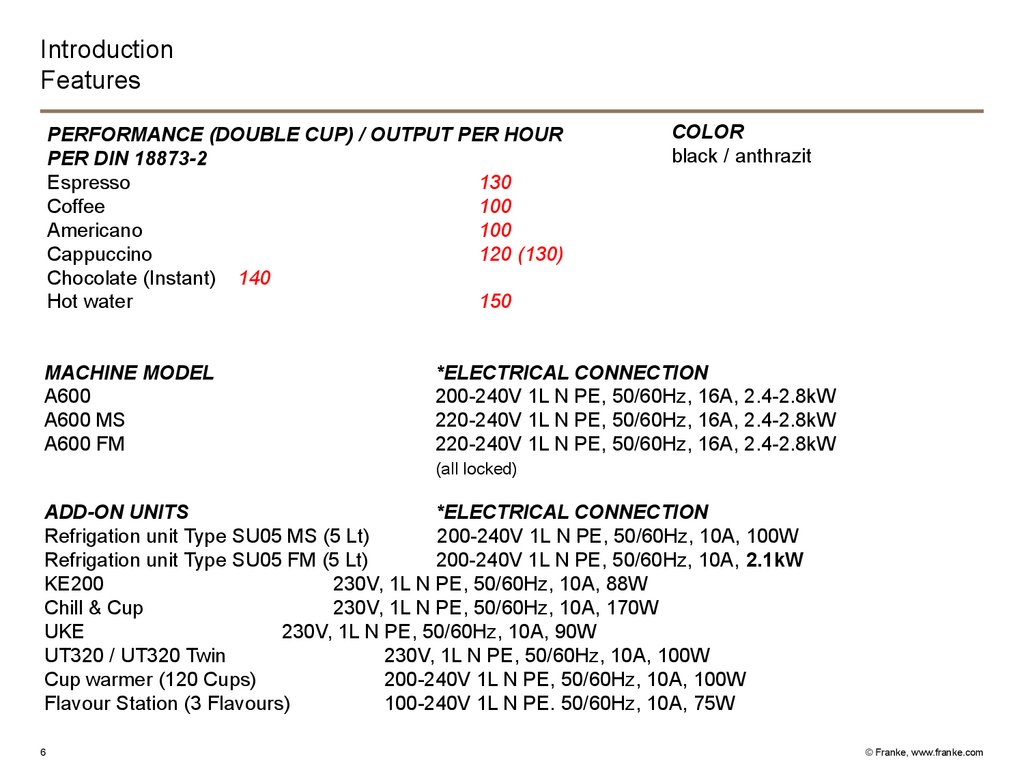
IntroductionFeatures
PERFORMANCE (DOUBLE CUP) / OUTPUT PER HOUR
PER DIN 18873-2
Espresso
130
Coffee
100
Americano
100
Cappuccino
120 (130)
Chocolate (Instant) 140
Hot water
150
MACHINE MODEL
A600
A600 MS
A600 FM
COLOR
black / anthrazit
*ELECTRICAL CONNECTION
200-240V 1L N PE, 50/60Hz, 16A, 2.4-2.8kW
220-240V 1L N PE, 50/60Hz, 16A, 2.4-2.8kW
220-240V 1L N PE, 50/60Hz, 16A, 2.4-2.8kW
(all locked)
ADD-ON UNITS
*ELECTRICAL CONNECTION
Refrigation unit Type SU05 MS (5 Lt)
200-240V 1L N PE, 50/60Hz, 10A, 100W
Refrigation unit Type SU05 FM (5 Lt)
200-240V 1L N PE, 50/60Hz, 10A, 2.1kW
KE200
230V, 1L N PE, 50/60Hz, 10A, 88W
Chill & Cup
230V, 1L N PE, 50/60Hz, 10A, 170W
UKE
230V, 1L N PE, 50/60Hz, 10A, 90W
UT320 / UT320 Twin
230V, 1L N PE, 50/60Hz, 10A, 100W
Cup warmer (120 Cups)
200-240V 1L N PE, 50/60Hz, 10A, 100W
Flavour Station (3 Flavours)
100-240V 1L N PE. 50/60Hz, 10A, 75W
6
© Franke, www.franke.com
7.
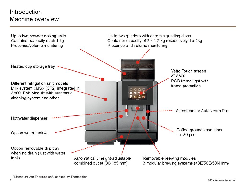
IntroductionMachine overview
Up to two powder dosing units
Container capacity each 1 kg
Presence/volume monitoring
Up to two grinders with ceramic grinding discs
Container capacity of 2 x 1.2 kg respectively 1 x 2kg
Presence and volume monitoring
Heated cup storage tray
Different refrigation unit models
Milk system «MS» (CF2) integrated in
A600. FM* Module with automatic
cleaning system and other
Vetro Touch screen
8’’ A600
RGB frame light with
frame protection
Autosteam or Autosteam Pro
Hot water dispenser
Coffee grounds container
ca. 80 pcs.
Option water tank 4lt
Option removable drip tray
when no drain (just with water
tank)
Automatically height-adjustable
combined outlet (80-185 mm)
Removable brewing modules
3 modular brewing systems (43E/50E/50N mm)
*Lizenziert von Thermoplan/Licensed by Thermoplan
7
© Franke, www.franke.com
8.
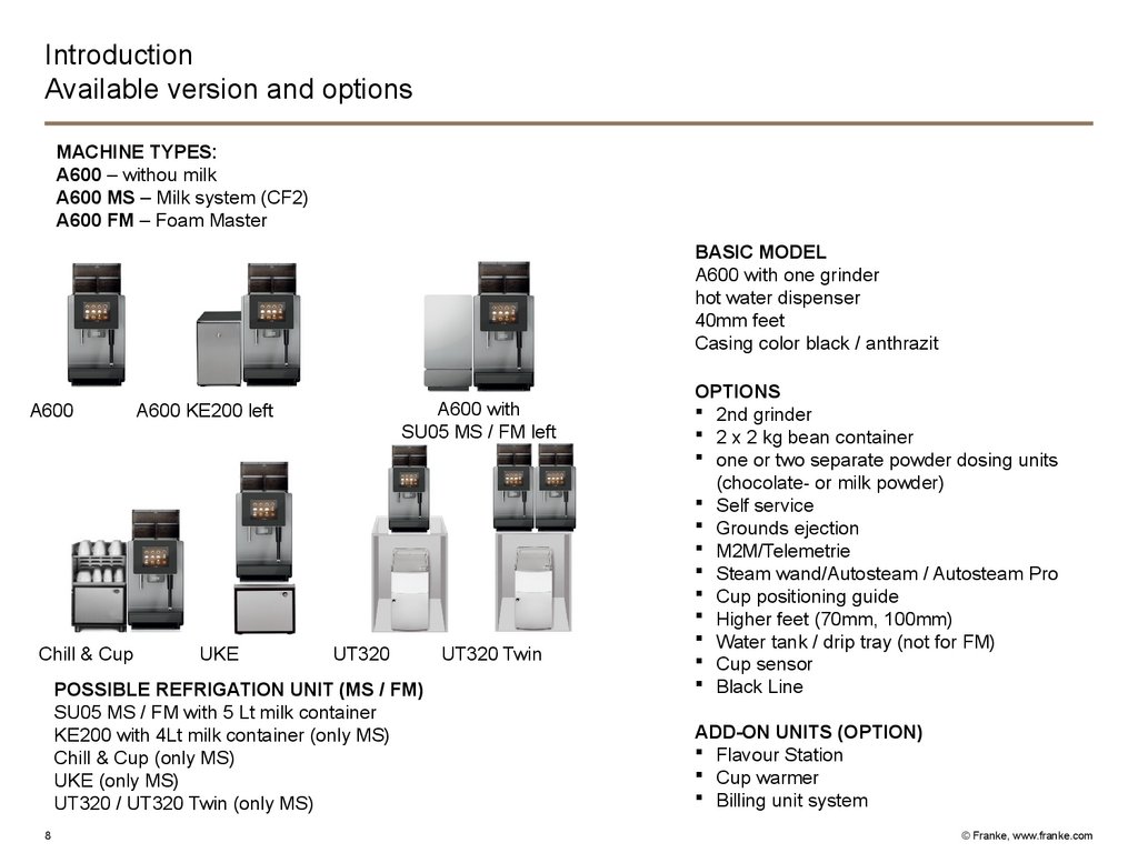
IntroductionAvailable version and options
MACHINE TYPES:
A600 – withou milk
A600 MS – Milk system (CF2)
A600 FM – Foam Master
BASIC MODEL
A600 with one grinder
hot water dispenser
40mm feet
Casing color black / anthrazit
A600
Chill & Cup
A600 with
SU05 MS / FM left
A600 KE200 left
UKE
UT320
POSSIBLE REFRIGATION UNIT (MS / FM)
SU05 MS / FM with 5 Lt milk container
KE200 with 4Lt milk container (only MS)
Chill & Cup (only MS)
UKE (only MS)
UT320 / UT320 Twin (only MS)
8
UT320 Twin
OPTIONS
2nd grinder
2 x 2 kg bean container
one or two separate powder dosing units
(chocolate- or milk powder)
Self service
Grounds ejection
M2M/Telemetrie
Steam wand/Autosteam / Autosteam Pro
Cup positioning guide
Higher feet (70mm, 100mm)
Water tank / drip tray (not for FM)
Cup sensor
Black Line
ADD-ON UNITS (OPTION)
Flavour Station
Cup warmer
Billing unit system
© Franke, www.franke.com
9.
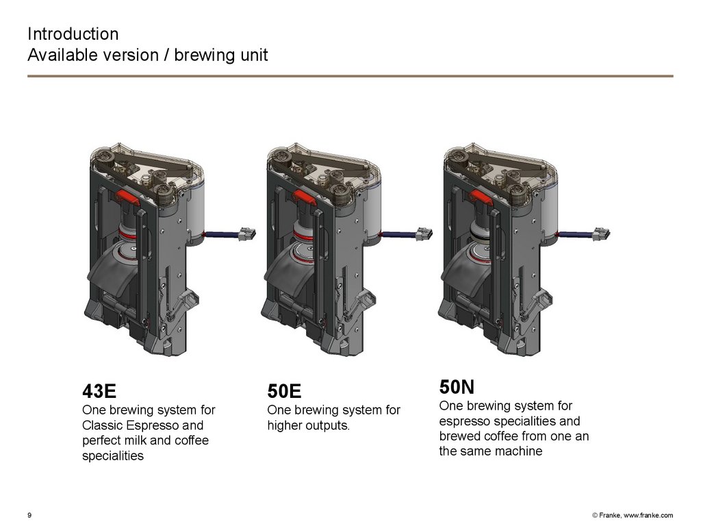
IntroductionAvailable version / brewing unit
9
43E
50E
One brewing system for
Classic Espresso and
perfect milk and coffee
specialities
One brewing system for
higher outputs.
50N
One brewing system for
espresso specialities and
brewed coffee from one an
the same machine
© Franke, www.franke.com
10.
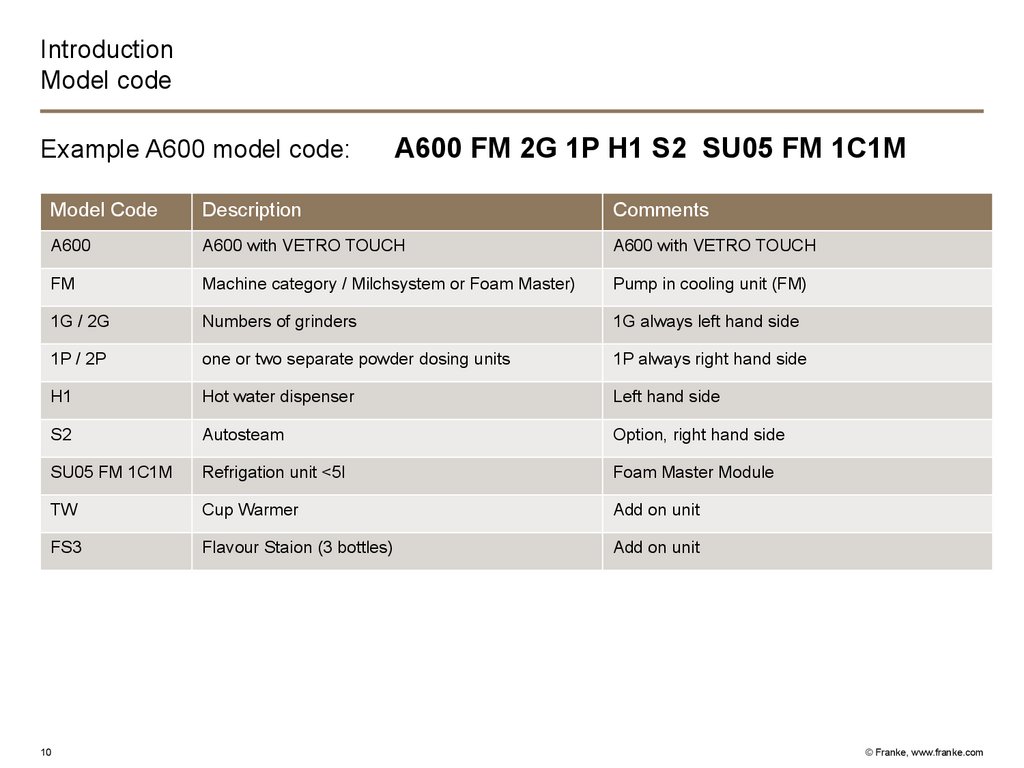
IntroductionModel code
Example A600 model code:
A600 FM 2G 1P H1 S2 SU05 FM 1C1M
Model Code
Description
Comments
A600
A600 with VETRO TOUCH
A600 with VETRO TOUCH
FM
Machine category / Milchsystem or Foam Master)
Pump in cooling unit (FM)
1G / 2G
Numbers of grinders
1G always left hand side
1P / 2P
one or two separate powder dosing units
1P always right hand side
H1
Hot water dispenser
Left hand side
S2
Autosteam
Option, right hand side
SU05 FM 1C1M
Refrigation unit <5l
Foam Master Module
TW
Cup Warmer
Add on unit
FS3
Flavour Staion (3 bottles)
Add on unit
10
© Franke, www.franke.com
11.
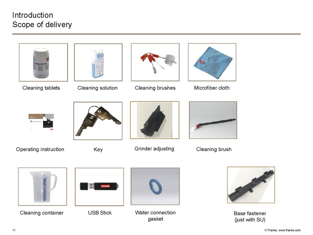
IntroductionScope of delivery
Cleaning tablets
Cleaning solution
Cleaning brushes
Operating instruction
Key
Grinder adjusting
USB Stick
Water connection
gasket
Cleaning container
11
Microfiber cloth
Cleaning brush
Base fastener
(just with SU)
© Franke, www.franke.com
12.
IntroductionHygiene
Short milk tubes between refrigerator and coffee machine
Milk pumps in the refrigerator
Improved cleaning possibilities of the coverplate
Automatic rinsing, cleaning and sanitizing program (ARCS)
Simple assembly and disassembly of the combined coffee, milk and instant
outlet.
- HACCP compliant (Hazard Analysis and Critical Control Points)
-
12
© Franke, www.franke.com
13.
IntroductionVetro Touch
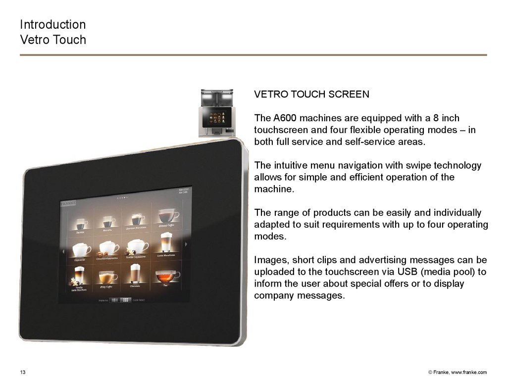
VETRO TOUCH SCREEN
The A600 machines are equipped with a 8 inch
touchscreen and four flexible operating modes – in
both full service and self-service areas.
The intuitive menu navigation with swipe technology
allows for simple and efficient operation of the
machine.
The range of products can be easily and individually
adapted to suit requirements with up to four operating
modes.
Images, short clips and advertising messages can be
uploaded to the touchscreen via USB (media pool) to
inform the user about special offers or to display
company messages.
13
© Franke, www.franke.com
14.
IntroductionThe 4 operating modes
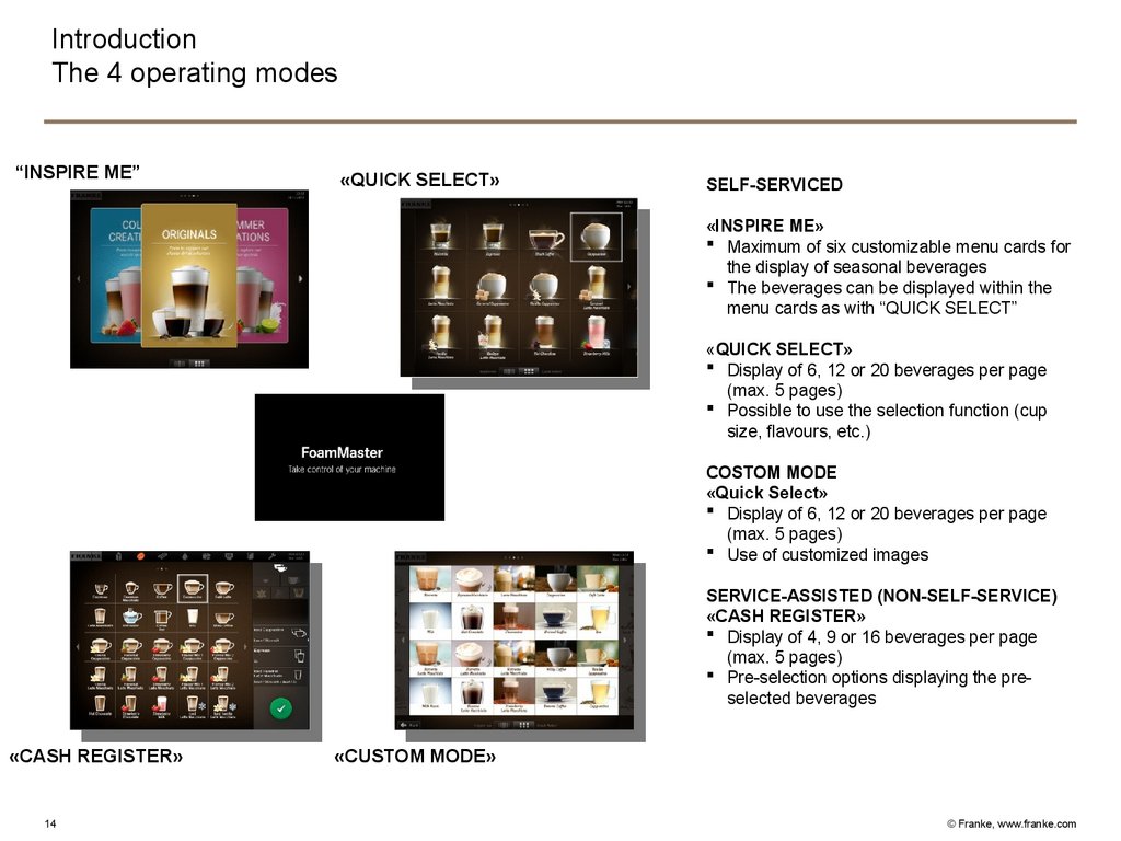
“INSPIRE ME”
«QUICK SELECT»
SELF-SERVICED
«INSPIRE ME»
Maximum of six customizable menu cards for
the display of seasonal beverages
The beverages can be displayed within the
menu cards as with “QUICK SELECT”
«QUICK SELECT»
Display of 6, 12 or 20 beverages per page
(max. 5 pages)
Possible to use the selection function (cup
size, flavours, etc.)
COSTOM MODE
«Quick Select»
Display of 6, 12 or 20 beverages per page
(max. 5 pages)
Use of customized images
SERVICE-ASSISTED (NON-SELF-SERVICE)
«CASH REGISTER»
Display of 4, 9 or 16 beverages per page
(max. 5 pages)
Pre-selection options displaying the preselected beverages
«CASH REGISTER»
14
«CUSTOM MODE»
© Franke, www.franke.com
15.
IntroductionInspire Me
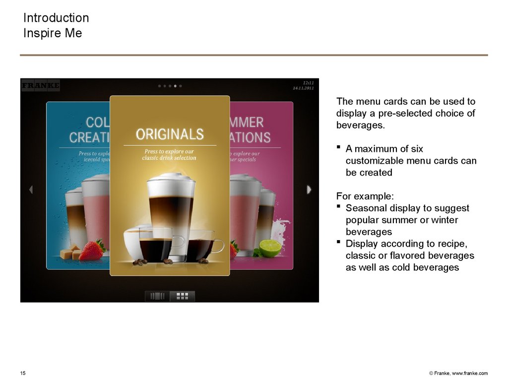
The menu cards can be used to
display a pre-selected choice of
beverages.
A maximum of six
customizable menu cards can
be created
For example:
Seasonal display to suggest
popular summer or winter
beverages
Display according to recipe,
classic or flavored beverages
as well as cold beverages
15
© Franke, www.franke.com
16.
IntroductionQuick Selection
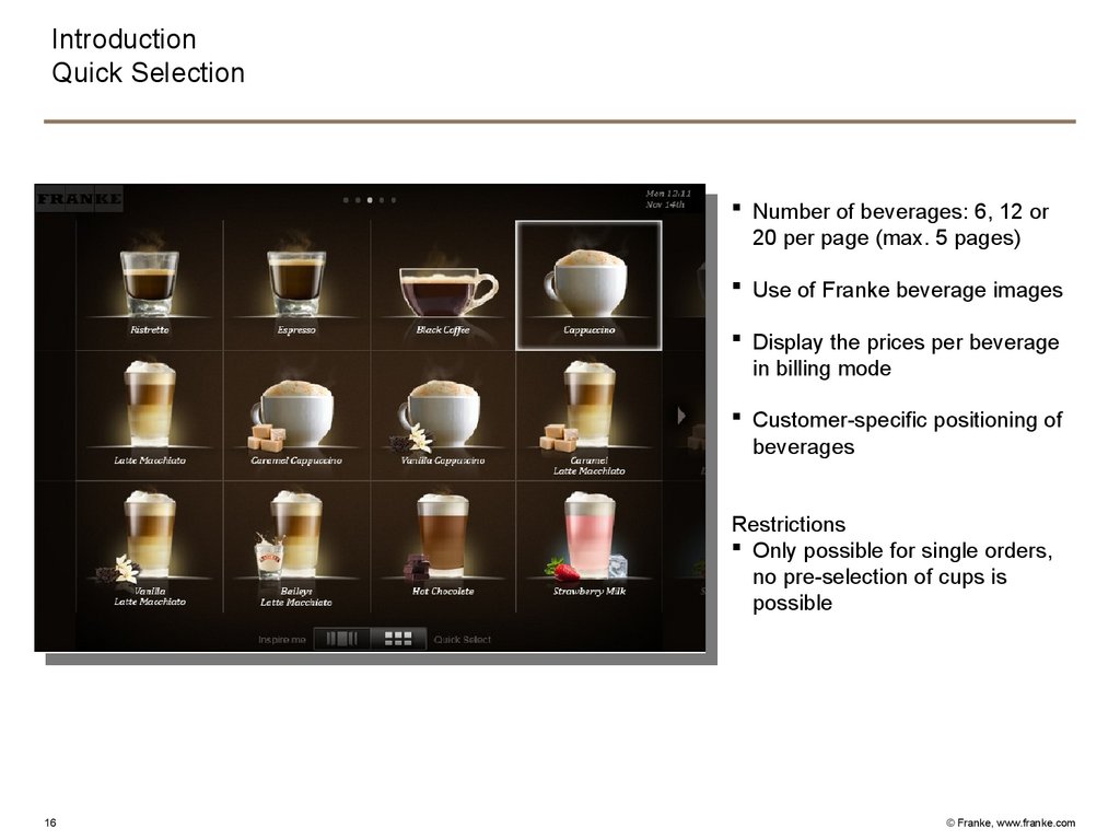
Number of beverages: 6, 12 or
20 per page (max. 5 pages)
Use of Franke beverage images
Display the prices per beverage
in billing mode
Customer-specific positioning of
beverages
Restrictions
Only possible for single orders,
no pre-selection of cups is
possible
16
© Franke, www.franke.com
17.
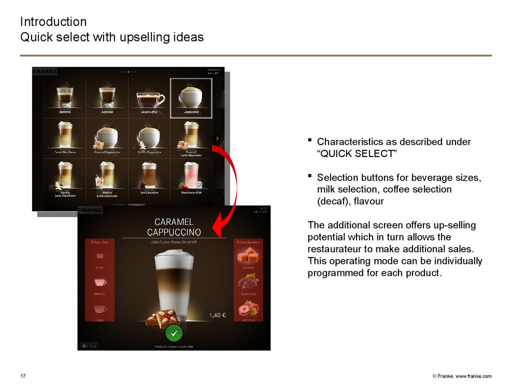
IntroductionQuick select with upselling ideas
Characteristics as described under
“QUICK SELECT”
Selection buttons for beverage sizes,
milk selection, coffee selection
(decaf), flavour
The additional screen offers up-selling
potential which in turn allows the
restaurateur to make additional sales.
This operating mode can be individually
programmed for each product.
17
© Franke, www.franke.com
18.
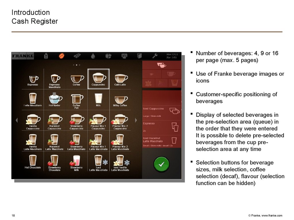
IntroductionCash Register
Number of beverages: 4, 9 or 16
per page (max. 5 pages)
Use of Franke beverage images or
icons
Customer-specific positioning of
beverages
Display of selected beverages in
the pre-selection area (queue) in
the order that they were entered
It is possible to delete pre-selected
beverages from the cup preselection area at any time
Selection buttons for beverage
sizes, milk selection, coffee
selection (decaf), flavour (selection
function can be hidden)
18
© Franke, www.franke.com
19.
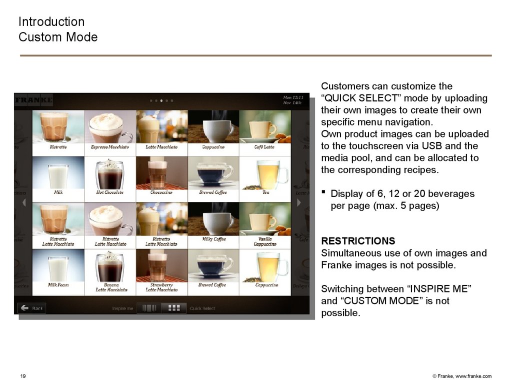
IntroductionCustom Mode
Customers can customize the
“QUICK SELECT” mode by uploading
their own images to create their own
specific menu navigation.
Own product images can be uploaded
to the touchscreen via USB and the
media pool, and can be allocated to
the corresponding recipes.
Display of 6, 12 or 20 beverages
per page (max. 5 pages)
RESTRICTIONS
Simultaneous use of own images and
Franke images is not possible.
Switching between “INSPIRE ME”
and “CUSTOM MODE” is not
possible.
19
© Franke, www.franke.com
20.
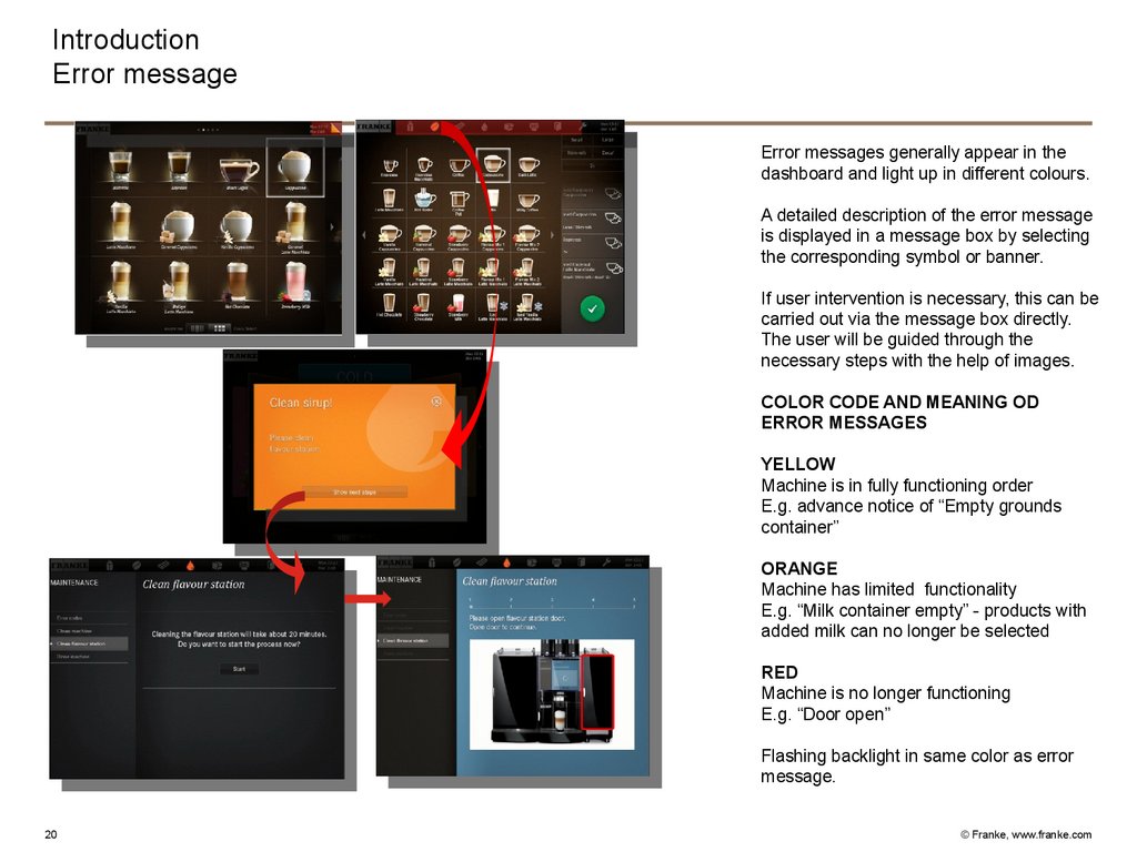
IntroductionError message
Error messages generally appear in the
dashboard and light up in different colours.
A detailed description of the error message
is displayed in a message box by selecting
the corresponding symbol or banner.
If user intervention is necessary, this can be
carried out via the message box directly.
The user will be guided through the
necessary steps with the help of images.
COLOR CODE AND MEANING OD
ERROR MESSAGES
YELLOW
Machine is in fully functioning order
E.g. advance notice of “Empty grounds
container”
ORANGE
Machine has limited functionality
E.g. “Milk container empty” - products with
added milk can no longer be selected
RED
Machine is no longer functioning
E.g. “Door open”
Flashing backlight in same color as error
message.
20
© Franke, www.franke.com
21.
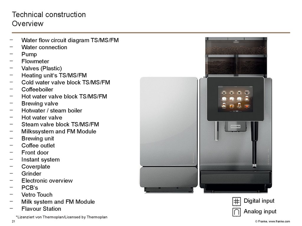
Technical constructionOverview
-
Water flow circuit diagram TS/MS/FM
Water connection
Pump
Flowmeter
Valves (Plastic)
Heating unit‘s TS/MS/FM
Cold water valve block TS/MS/FM
Coffeeboiler
Hot water valve block TS/MS/FM
Brewing valve
Hotwater / steam boiler
Hot water valve
Steam valve block TS/MS/FM
Milkssystem and FM Module
Brewing unit
Coffee outlet
Front door
Instant system
Coverplate
Grinder
Electronic overview
PCB‘s
Vetro Touch
Milk system and FM Module
Flavour Station
Digital input
Analog input
*Lizenziert von Thermoplan/Licensed by Thermoplan
21
© Franke, www.franke.com
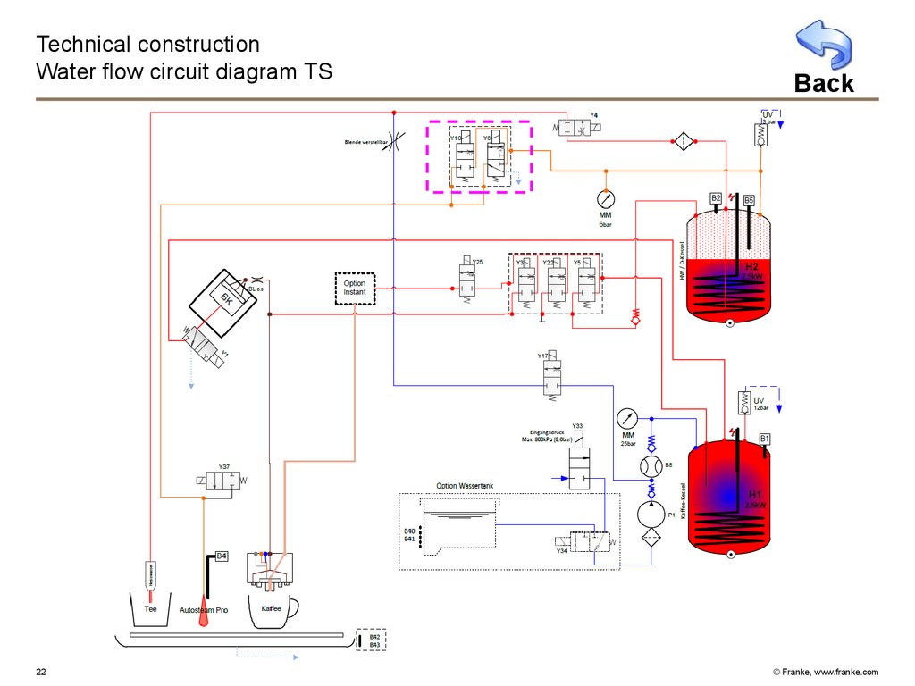
22.
Technical constructionWater flow circuit diagram TS
22
Back
© Franke, www.franke.com
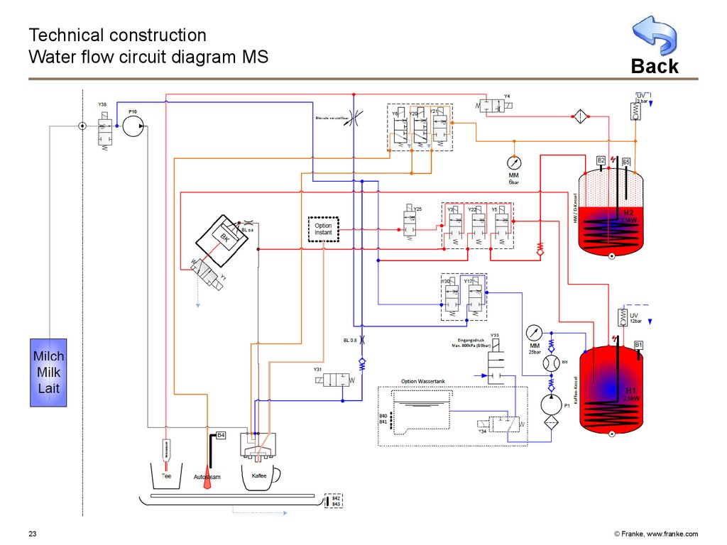
23.
Technical constructionWater flow circuit diagram MS
23
Back
© Franke, www.franke.com
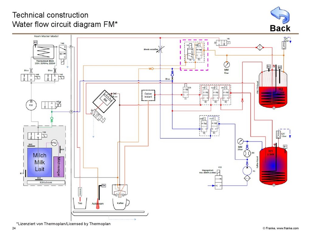
24.
Technical constructionWater flow circuit diagram FM*
Back
*Lizenziert von Thermoplan/Licensed by Thermoplan
24
© Franke, www.franke.com
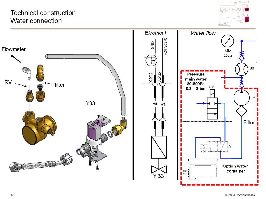
25.
Technical constructionWater connection
Electrical
Water flow
filter
X202
RV
X202
Flowmeter
Pressure
main water
80-800Pa
0.8 – 8 bar
RV
wt wt
Y33
Filter
Option water
container
25
© Franke, www.franke.com
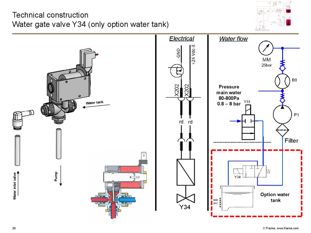
26.
Technical constructionWater gate valve Y34 (only option water tank)
X202
X202
Electrical
Water tank
rd
rt
Water flow
Pressure
main water
80-800Pa
0.8 – 8 bar
rt
rd
Pump
Water inlet valve
Filter
Option water
tank
Y34
26
© Franke, www.franke.com
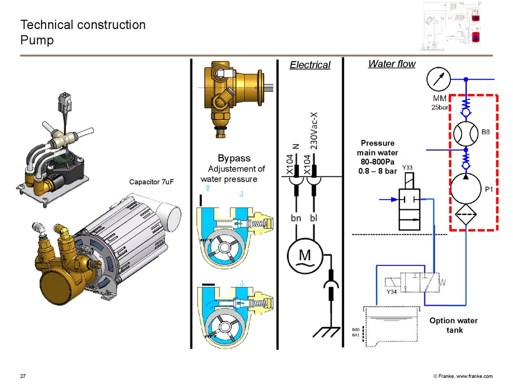
27.
Technical constructionPump
Capacitor 7uF
Adjustement of
water pressure
X104
Bypass
X104
Electrical
Water flow
Pressure
main water
80-800Pa
0.8 – 8 bar
Option water
tank
27
© Franke, www.franke.com
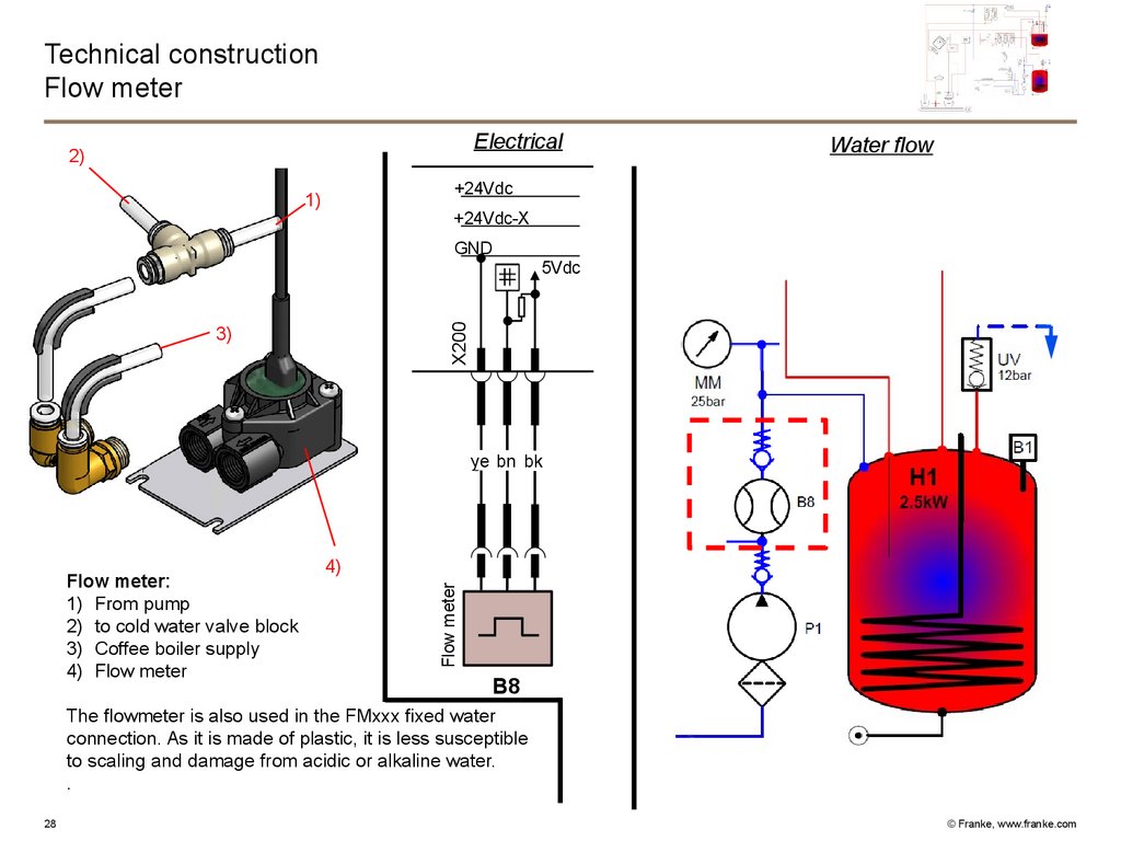
28.
Technical constructionFlow meter
Electrical
2)
Water flow
+24Vdc
1)
+24Vdc-X
GND
X200
5Vdc
3)
ye
gb bn
bn bk
sw
4)
Flow meter
Flow meter:
1) From pump
2) to cold water valve block
3) Coffee boiler supply
4) Flow meter
B8
The flowmeter is also used in the FMxxx fixed water
connection. As it is made of plastic, it is less susceptible
to scaling and damage from acidic or alkaline water.
.
28
© Franke, www.franke.com
29.
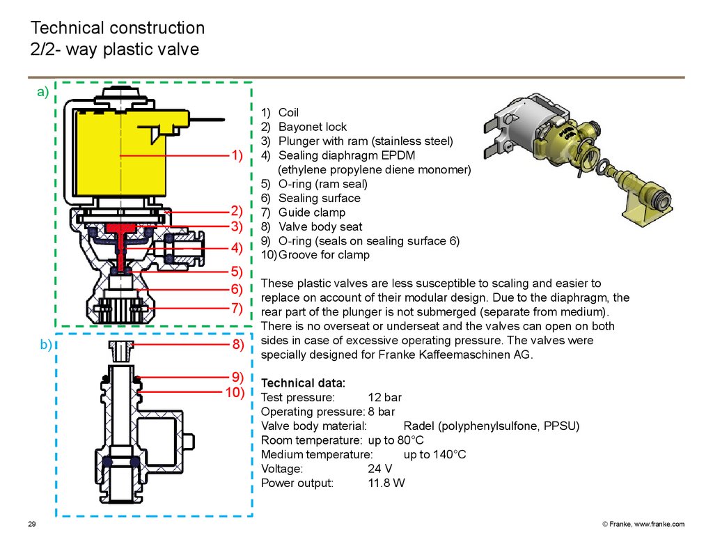
Technical construction2/2- way plastic valve
a)
1)
2)
3)
4)
5)
6)
7)
b)
8)
9)
10)
29
1)
2)
3)
4)
Coil
Bayonet lock
Plunger with ram (stainless steel)
Sealing diaphragm EPDM
(ethylene propylene diene monomer)
5) O-ring (ram seal)
6) Sealing surface
7) Guide clamp
8) Valve body seat
9) O-ring (seals on sealing surface 6)
10)Groove for clamp
These plastic valves are less susceptible to scaling and easier to
replace on account of their modular design. Due to the diaphragm, the
rear part of the plunger is not submerged (separate from medium).
There is no overseat or underseat and the valves can open on both
sides in case of excessive operating pressure. The valves were
specially designed for Franke Kaffeemaschinen AG.
Technical data:
Test pressure:
12 bar
Operating pressure: 8 bar
Valve body material:
Radel (polyphenylsulfone, PPSU)
Room temperature: up to 80°C
Medium temperature:
up to 140°C
Voltage:
24 V
Power output:
11.8 W
© Franke, www.franke.com
30.
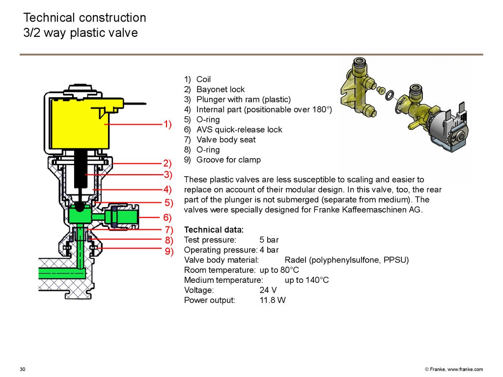
Technical construction3/2 way plastic valve
1)
2)
3)
4)
5)
6)
7)
8)
9)
30
1)
2)
3)
4)
5)
6)
7)
8)
9)
Coil
Bayonet lock
Plunger with ram (plastic)
Internal part (positionable over 180°)
O-ring
AVS quick-release lock
Valve body seat
O-ring
Groove for clamp
These plastic valves are less susceptible to scaling and easier to
replace on account of their modular design. In this valve, too, the rear
part of the plunger is not submerged (separate from medium). The
valves were specially designed for Franke Kaffeemaschinen AG.
Technical data:
Test pressure:
5 bar
Operating pressure: 4 bar
Valve body material:
Radel (polyphenylsulfone, PPSU)
Room temperature: up to 80°C
Medium temperature:
up to 140°C
Voltage:
24 V
Power output:
11.8 W
© Franke, www.franke.com
31.
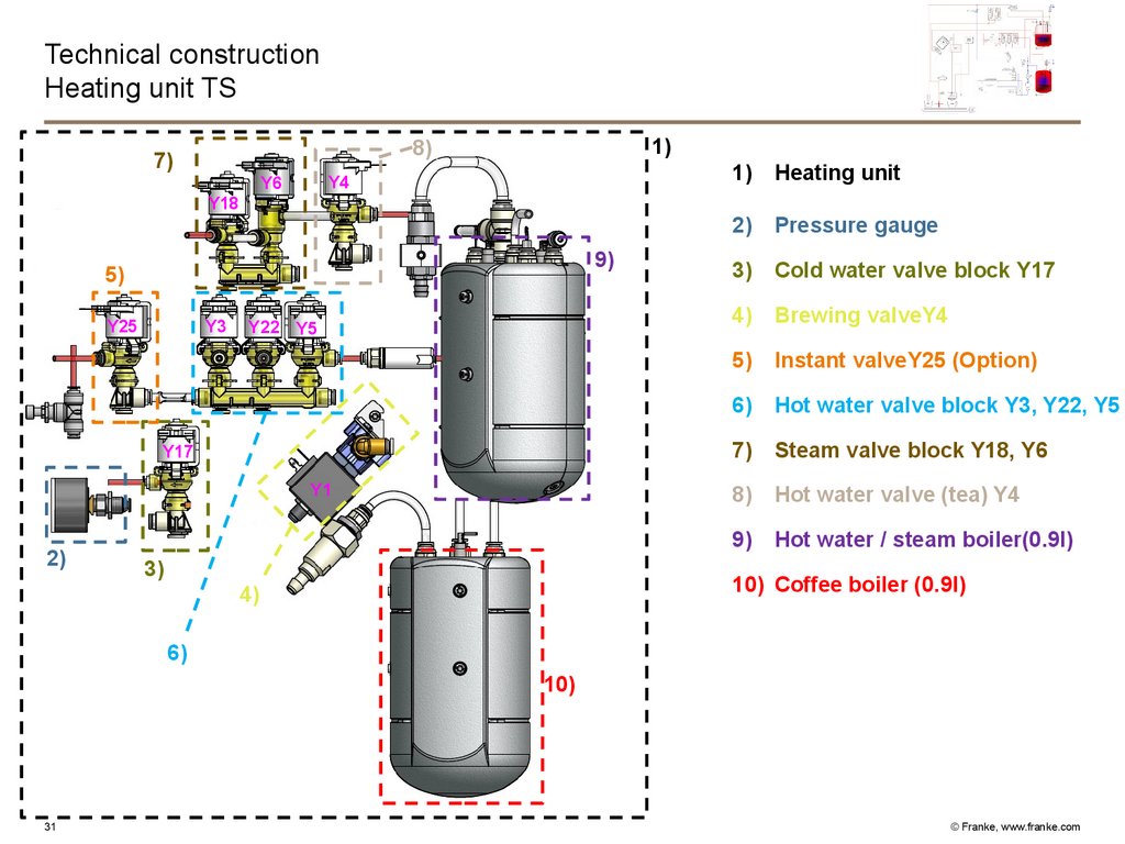
Technical constructionHeating unit TS
1)
8)
7)
Y4
Y6
Y18
9)
5)
Y25
Y3
Y22 Y5
Y17
Y1
2)
3)
1)
Heating unit
2)
Pressure gauge
3)
Cold water valve block Y17
4)
Brewing valveY4
5)
Instant valveY25 (Option)
6)
Hot water valve block Y3, Y22, Y5
7)
Steam valve block Y18, Y6
8)
Hot water valve (tea) Y4
9)
Hot water / steam boiler(0.9l)
10) Coffee boiler (0.9l)
4)
6)
10)
31
© Franke, www.franke.com
32.
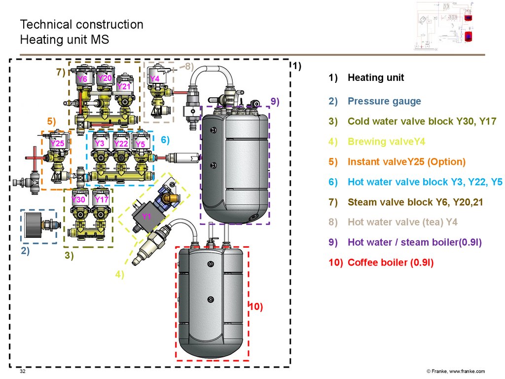
Technical constructionHeating unit MS
1)
8)
7)
Y6
Y20
Y4
Y21
9)
5)
Y25
Y3
Y30
Y22 Y5
6)
Y17
Y1
2)
3)
1)
Heating unit
2)
Pressure gauge
3)
Cold water valve block Y30, Y17
4)
Brewing valveY4
5)
Instant valveY25 (Option)
6)
Hot water valve block Y3, Y22, Y5
7)
Steam valve block Y6, Y20,21
8)
Hot water valve (tea) Y4
9)
Hot water / steam boiler(0.9l)
10) Coffee boiler (0.9l)
4)
10)
32
© Franke, www.franke.com
33.
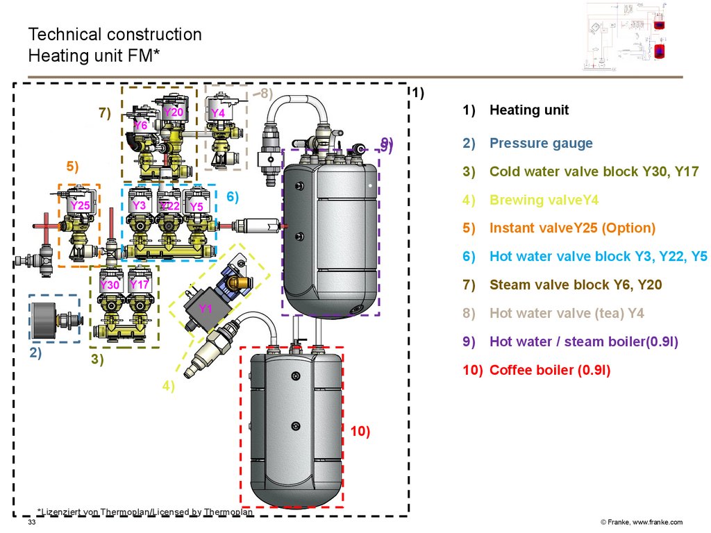
Technical constructionHeating unit FM*
1)
8)
7)
Y20
Y4
9)
9)
5)
Y25
Y3
Y30
Y22 Y5
6)
Y17
Y1
2)
1)
Heating unit
2)
Pressure gauge
3)
Cold water valve block Y30, Y17
4)
Brewing valveY4
5)
Instant valveY25 (Option)
6)
Hot water valve block Y3, Y22, Y5
7)
Steam valve block Y6, Y20
8)
Hot water valve (tea) Y4
9)
Hot water / steam boiler(0.9l)
Y6
3)
10) Coffee boiler (0.9l)
4)
10)
*Lizenziert von Thermoplan/Licensed by Thermoplan
33
© Franke, www.franke.com
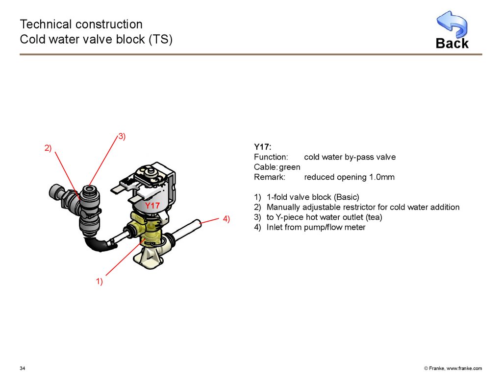
34.
Technical constructionCold water valve block (TS)
Back
3)
Y17:
Function:
cold water by-pass valve
Cable: green
Remark:
reduced opening 1.0mm
2)
Y17
4)
1)
2)
3)
4)
1-fold valve block (Basic)
Manually adjustable restrictor for cold water addition
to Y-piece hot water outlet (tea)
Inlet from pump/flow meter
1)
34
© Franke, www.franke.com
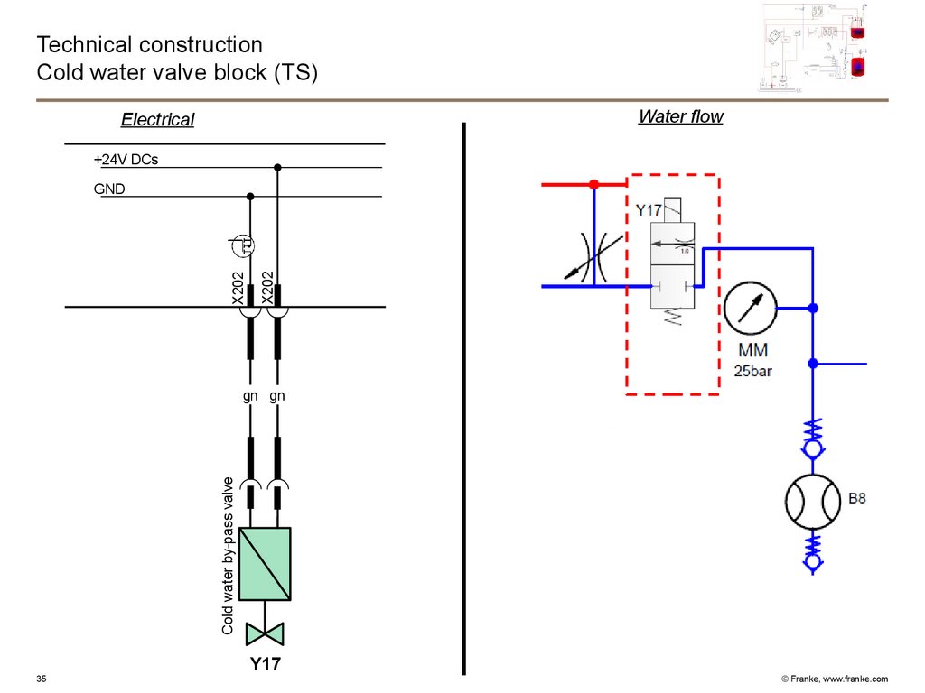
35.
Technical constructionCold water valve block (TS)
Water flow
Electrical
+24V DCs
X202
X202
GND
Cold water by-pass valve
gn gn
Y17
35
© Franke, www.franke.com
36.
Technical constructionCold water valve block (MS)
Back
Y30:
Function:
cold water rinsing line
Cable: white
Remark:
opening 3.0 mm
3)
Y17
2)
Y30
Y17:
Function:
cold water by-pass valve
Cable: green
Remark:
reduced opening 1.0 mm
1)
2)
3)
4)
5)
2-fold valve block (Basic)
Manually adjustable restrictor for cold water addition
to Y-piece hot water outlet (tea)
to milk line/milk pump
Inlet from pump/flow meter
5)
4)
1)
36
© Franke, www.franke.com
37.
Technical constructionCold water valve block (MS)
Water flow
Electrical
+24V DCs
rd
rd
Cold water rinsing
Cold water by-pass valve
gn gn
Y17
37
X203
X203
X202
X202
GND
Y30
© Franke, www.franke.com
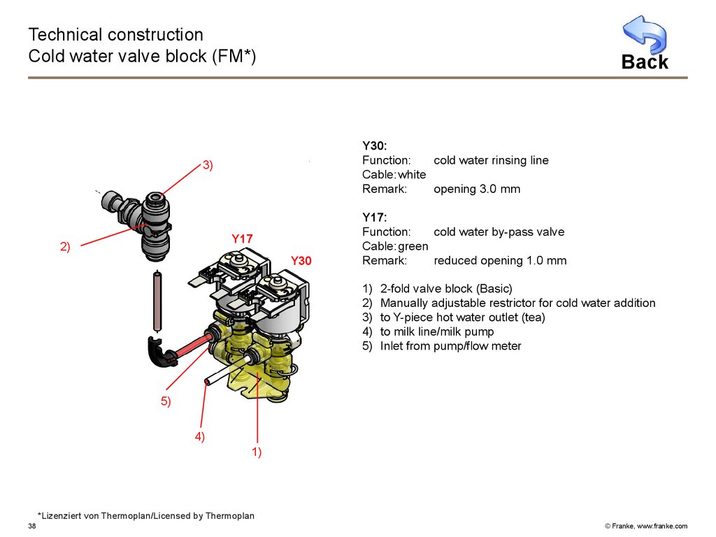
38.
Technical constructionCold water valve block (FM*)
Back
Y30:
Function:
cold water rinsing line
Cable: white
Remark:
opening 3.0 mm
3)
Y17
2)
Y30
Y17:
Function:
cold water by-pass valve
Cable: green
Remark:
reduced opening 1.0 mm
1)
2)
3)
4)
5)
2-fold valve block (Basic)
Manually adjustable restrictor for cold water addition
to Y-piece hot water outlet (tea)
to milk line/milk pump
Inlet from pump/flow meter
5)
4)
1)
*Lizenziert von Thermoplan/Licensed by Thermoplan
38
© Franke, www.franke.com
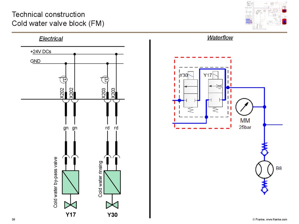
39.
Technical constructionCold water valve block (FM)
Waterflow
Electrical
+24V DCs
rd
rd
Cold water rinsing
Cold water by-pass valve
gn gn
Y17
39
X203
X203
X202
X202
GND
Y30
© Franke, www.franke.com
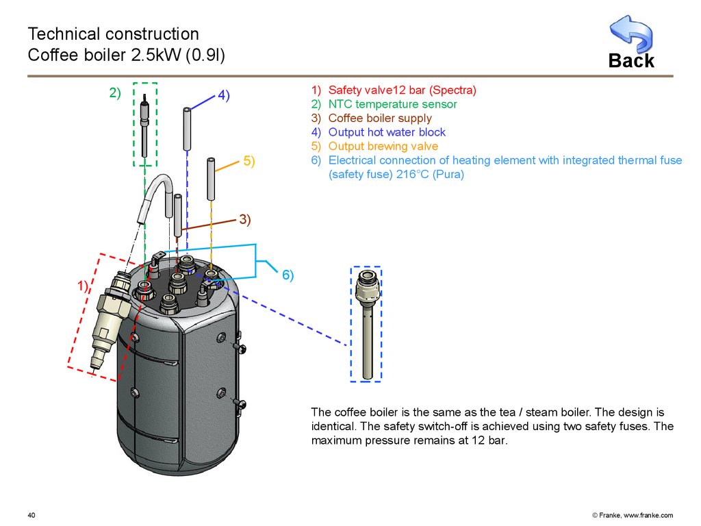
40.
Technical constructionCoffee boiler 2.5kW (0.9l)
2)
Back
1)
2)
3)
4)
5)
6)
4)
5)
Safety valve12 bar (Spectra)
NTC temperature sensor
Coffee boiler supply
Output hot water block
Output brewing valve
Electrical connection of heating element with integrated thermal fuse
(safety fuse) 216°C (Pura)
3)
1)
6)
The coffee boiler is the same as the tea / steam boiler. The design is
identical. The safety switch-off is achieved using two safety fuses. The
maximum pressure remains at 12 bar.
40
© Franke, www.franke.com
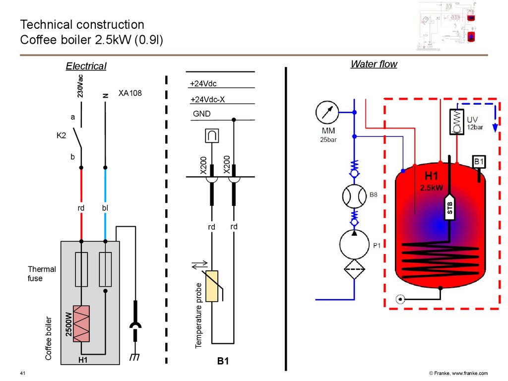
41.
Technical constructionCoffee boiler 2.5kW (0.9l)
Water flow
+24Vdc
N
230Vac
Electrical
XA108
+24Vdc-X
GND
a
rd
STB
X200
b
X200
K2
bl
rd
rd
41
Temperature probe
2500W
Coffee boiler
Thermal
fuse
H1
B1
© Franke, www.franke.com
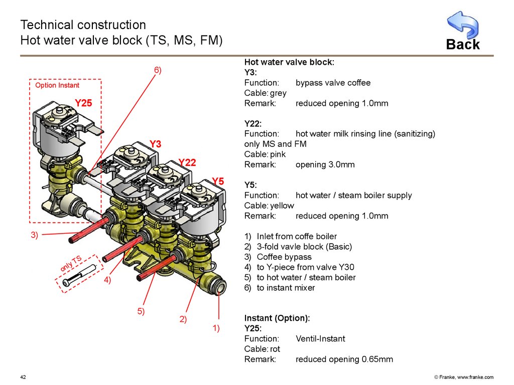
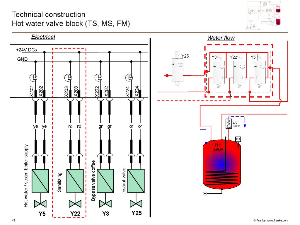
42.
Technical constructionHot water valve block (TS, MS, FM)
Hot water valve block:
Y3:
Function:
bypass valve coffee
Cable: grey
Remark:
reduced opening 1.0mm
6)
Option Instant
Y25
Y22:
Function:
hot water milk rinsing line (sanitizing)
only MS and FM
Cable: pink
Remark:
opening 3.0mm
Y3
Y22
Y5
3)
Y5:
Function:
hot water / steam boiler supply
Cable: yellow
Remark:
reduced opening 1.0mm
1)
2)
3)
4)
5)
6)
TS
ly
n
o
4)
5)
42
Back
2)
1)
Inlet from coffe boiler
3-fold vavle block (Basic)
Coffee bypass
to Y-piece from valve Y30
to hot water / steam boiler
to instant mixer
Instant (Option):
Y25:
Function:
Ventil-Instant
Cable: rot
Remark:
reduced opening 0.65mm
© Franke, www.franke.com
43.
Technical constructionHot water valve block (TS, MS, FM)
Electrical
Water flow
+24V DCs
Y5
Y22
X224
X224
X202
X202
gr
rd
or
gr
or
Instant valve
Bypass valve coffee
rd
Sanitizing
Hot water / steam boiler supply
ye ye
43
X203
X203
X202
X202
GND
Y3
Y25
© Franke, www.franke.com
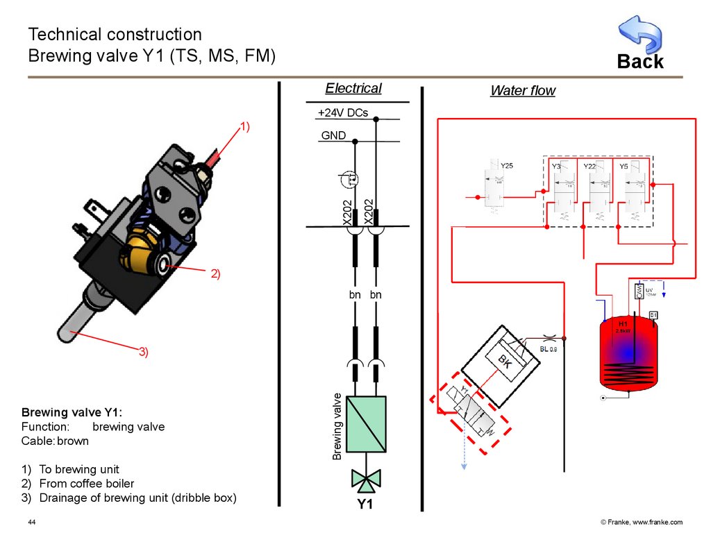
44.
Technical constructionBrewing valve Y1 (TS, MS, FM)
Back
Electrical
Water flow
+24V DCs
X202
GND
X202
1)
2)
bn bn
Brewing valve Y1:
Function:
brewing valve
Cable: brown
1) To brewing unit
2) From coffee boiler
3) Drainage of brewing unit (dribble box)
44
Brewing valve
3)
Y1
© Franke, www.franke.com
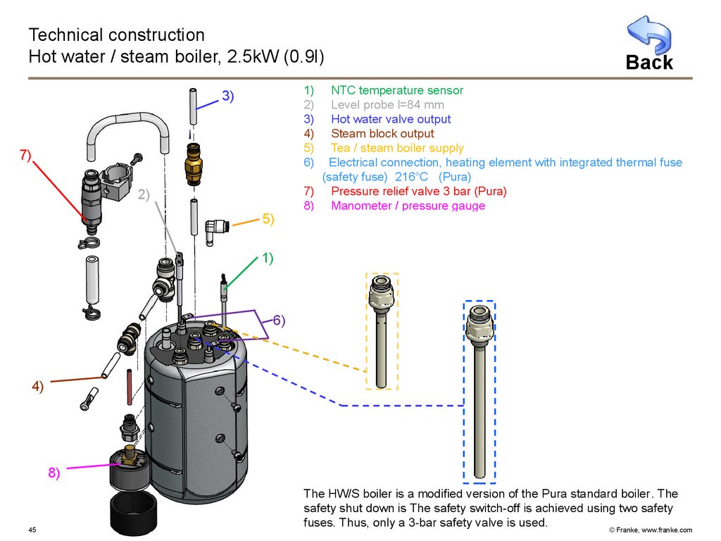
45.
Technical constructionHot water / steam boiler, 2.5kW (0.9l)
Back
1)
2)
3)
4)
5)
6)
3)
7)
2)
5)
NTC temperature sensor
Level probe l=84 mm
Hot water valve output
Steam block output
Tea / steam boiler supply
Electrical connection, heating element with integrated thermal fuse
(safety fuse) 216°C (Pura)
7) Pressure relief valve 3 bar (Pura)
8) Manometer / pressure gauge
1)
6)
4)
8)
45
The HW/S boiler is a modified version of the Pura standard boiler. The
safety shut down is The safety switch-off is achieved using two safety
fuses. Thus, only a 3-bar safety valve is used.
© Franke, www.franke.com
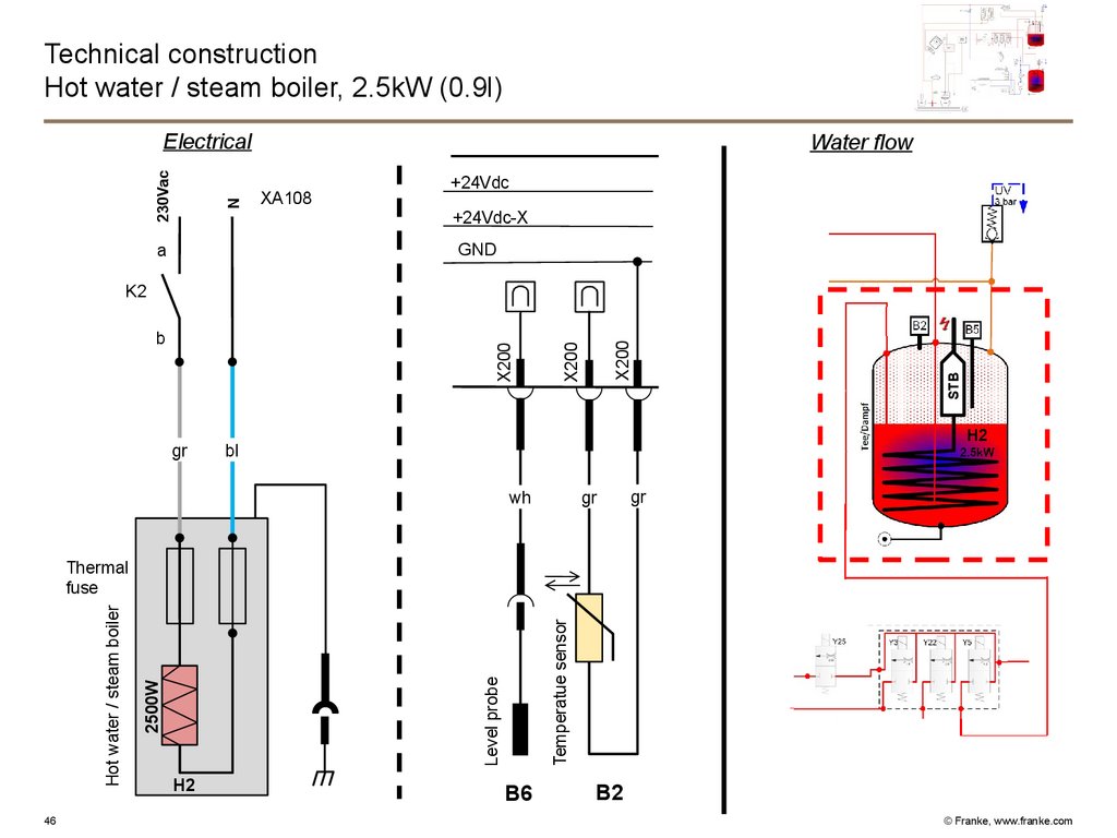
46.
Technical constructionHot water / steam boiler, 2.5kW (0.9l)
N
230Vac
Electrical
Water flow
XA108
+24Vdc
+24Vdc-X
GND
a
gr
STB
X200
X200
b
X200
K2
bl
gr
wh
gr
46
Temperatue sensor
Level probe
2500W
Hot water / steam boiler
Thermal
fuse
H2
B6
B2
© Franke, www.franke.com
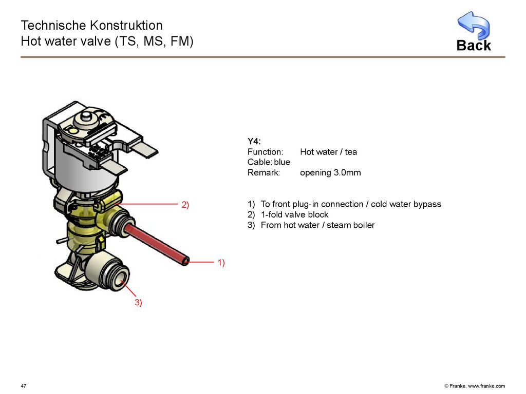
47.
Technische KonstruktionHot water valve (TS, MS, FM)
Back
Y4:
Function:
Cable: blue
Remark:
Hot water / tea
opening 3.0mm
1) To front plug-in connection / cold water bypass
2) 1-fold valve block
3) From hot water / steam boiler
2)
1)
3)
47
© Franke, www.franke.com
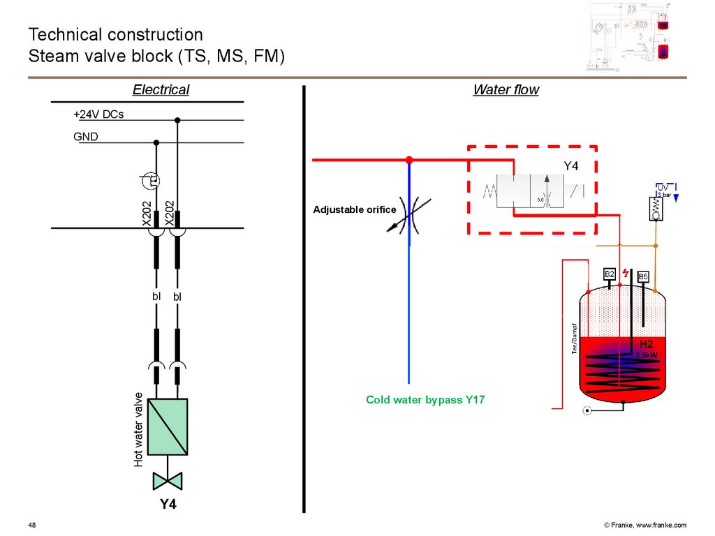
48.
Technical constructionSteam valve block (TS, MS, FM)
Electrical
Water flow
+24V DCs
X202
X202
GND
bl
Hot water valve
bl
Adjustable orifice
Cold water bypass Y17
Y4
48
© Franke, www.franke.com
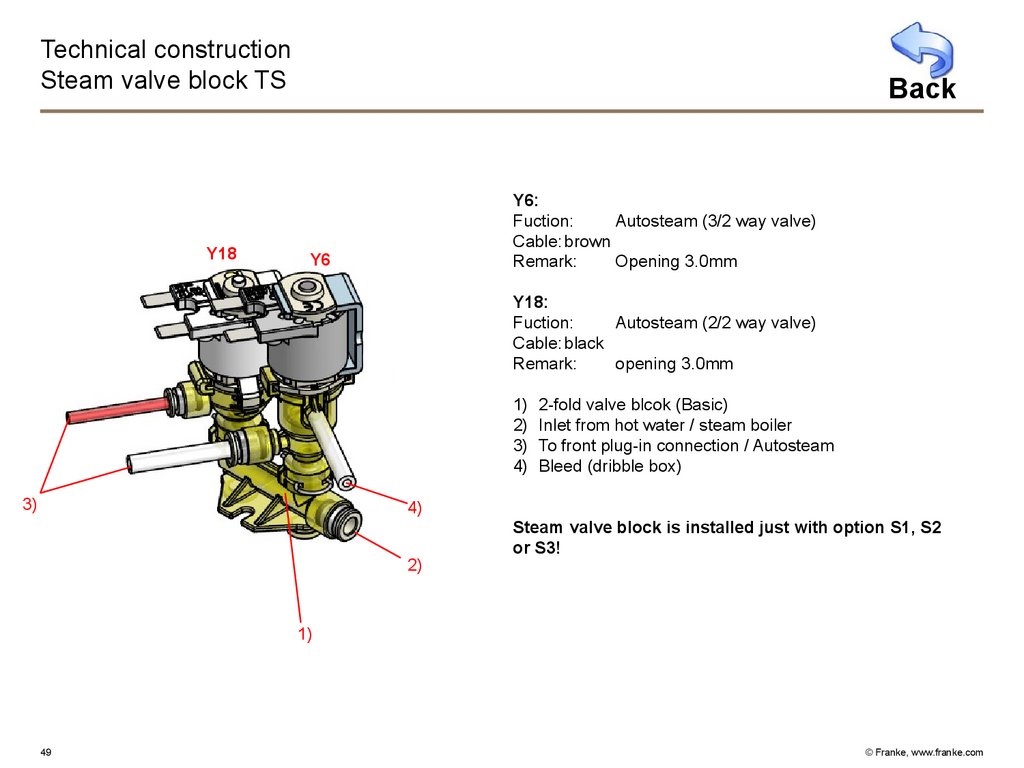
49.
Technical constructionSteam valve block TS
Y18
Back
Y6:
Fuction:
Autosteam (3/2 way valve)
Cable: brown
Remark:
Opening 3.0mm
Y6
Y18:
Fuction:
Autosteam (2/2 way valve)
Cable: black
Remark:
opening 3.0mm
1)
2)
3)
4)
3)
2-fold valve blcok (Basic)
Inlet from hot water / steam boiler
To front plug-in connection / Autosteam
Bleed (dribble box)
4)
2)
Steam valve block is installed just with option S1, S2
or S3!
1)
49
© Franke, www.franke.com
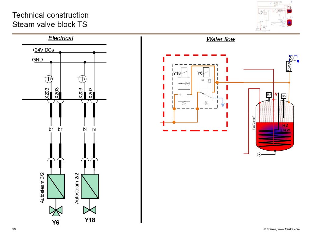
50.
Technical constructionSteam valve block TS
Electrical
Water flow
+24V DCs
br
Y6
50
X203
bl
bl
Autosteam 2/2
Autosteam 3/2
br
X203
X203
X203
GND
Y18
© Franke, www.franke.com
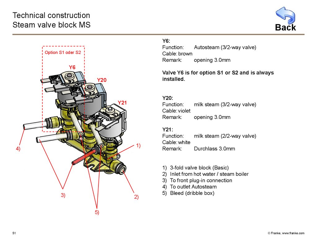
51.
Technical constructionSteam valve block MS
Back
Y6:
Function:
Autosteam (3/2-way valve)
Cable: brown
Remark:
opening 3.0mm
Option S1 oder S2
Y6
Valve Y6 is for option S1 or S2 and is always
installed.
Y20
Y20:
Function:
milk steam (3/2-way valve)
Cable: violet
Remark:
opening 3.0mm
Y21
1)
4)
3)
2)
Y21:
Function:
milk steam (2/2-way valve)
Cable: white
Remark:
Durchlass 3.0mm
1)
2)
3)
4)
5)
3-fold valve block (Basic)
Inlet from hot water / steam boiler
To front plug-in connection
To outlet Autosteam
Bleed (dribble box)
5)
51
© Franke, www.franke.com
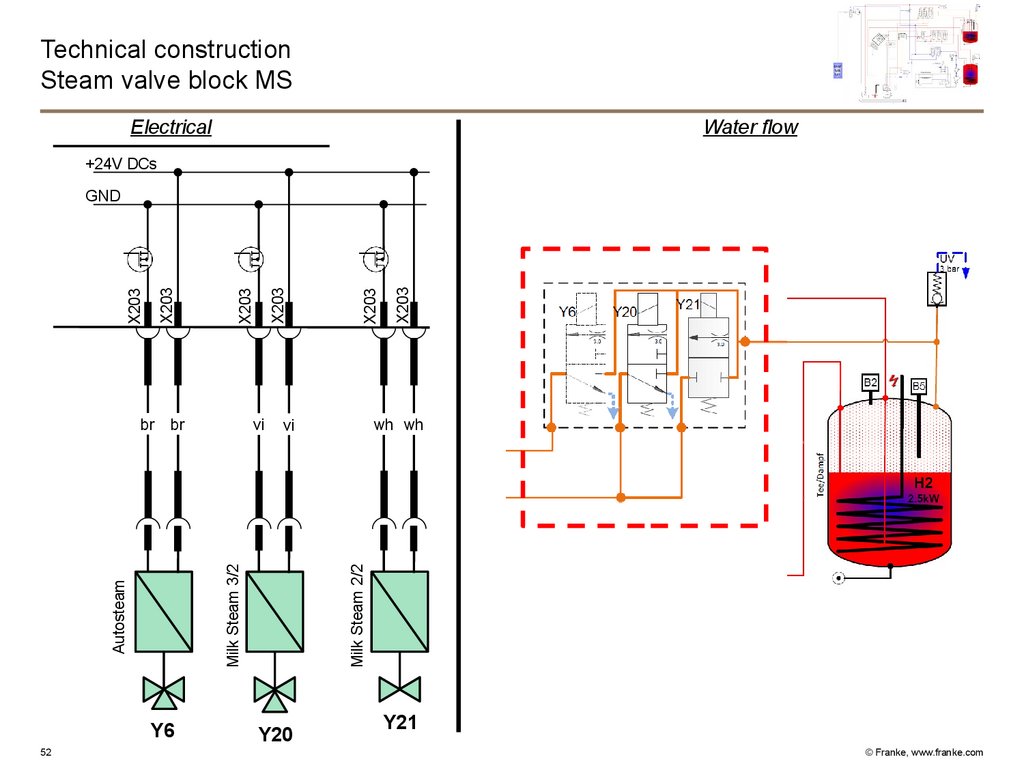
52.
Technical constructionSteam valve block MS
Electrical
Water flow
+24V DCs
br
X203
X203
X203
wh wh
vi
Milk Steam 2/2
Autosteam
Y6
52
vi
Milk Steam 3/2
br
X203
X203
X203
GND
Y20
Y21
© Franke, www.franke.com
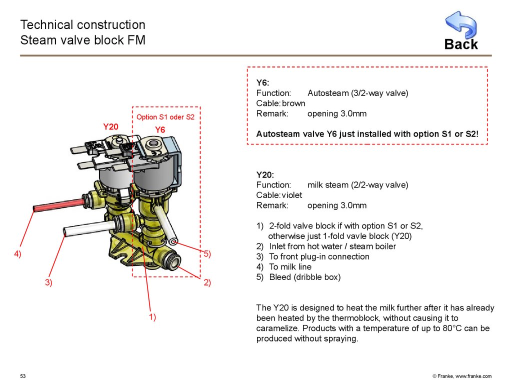
53.
Technical constructionSteam valve block FM
Back
Y6:
Function:
Autosteam (3/2-way valve)
Cable: brown
Remark:
opening 3.0mm
Option S1 oder S2
Y20
Y6
Autosteam valve Y6 just installed with option S1 or S2!
Y20:
Function:
milk steam (2/2-way valve)
Cable: violet
Remark:
opening 3.0mm
4)
5)
3)
2)
1)
53
1) 2-fold valve block if with option S1 or S2,
otherwise just 1-fold vavle block (Y20)
2) Inlet from hot water / steam boiler
3) To front plug-in connection
4) To milk line
5) Bleed (dribble box)
The Y20 is designed to heat the milk further after it has already
been heated by the thermoblock, without causing it to
caramelize. Products with a temperature of up to 80°C can be
produced without spraying.
© Franke, www.franke.com
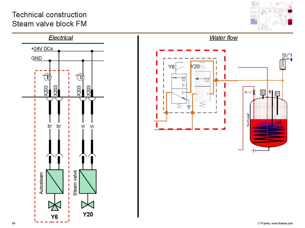
54.
Technical constructionSteam valve block FM
Electrical
Water flow
+24V DCs
br
Autosteam
Y6
54
X203
vi
vi
Steam valve
br
X203
X203
X203
GND
Y20
© Franke, www.franke.com
55.
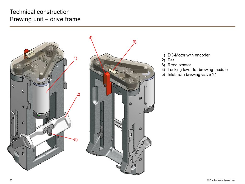
Technical constructionBrewing unit – drive frame
4)
11)
3)
1)
2)
3)
4)
5)
DC-Motor with encoder
Bar
Reed sensor
Locking lever for brewing module
Inlet from brewing valve Y1
2)
5)
55
© Franke, www.franke.com
56.
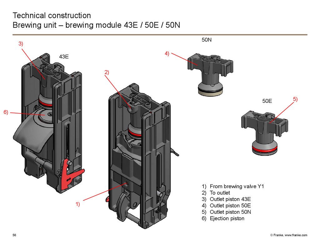
Technical constructionBrewing unit – brewing module 43E / 50E / 50N
50N
3)
4)
43E
2)
50E
5)
6)
1)
56
1)
2)
3)
4)
5)
6)
From brewing valve Y1
To outlet
Outlet piston 43E
Outlet piston 50E
Outlet piston 50N
Ejection piston
© Franke, www.franke.com
57.
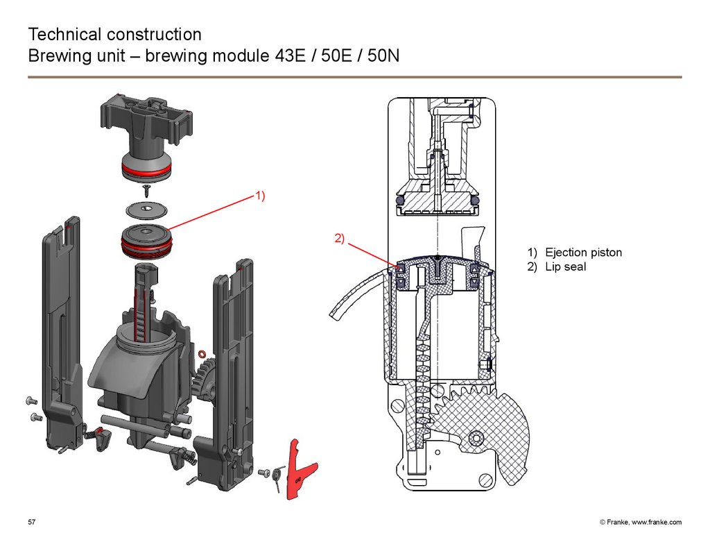
Technical constructionBrewing unit – brewing module 43E / 50E / 50N
1)
2)
1) Ejection piston
2) Lip seal
57
© Franke, www.franke.com
58.
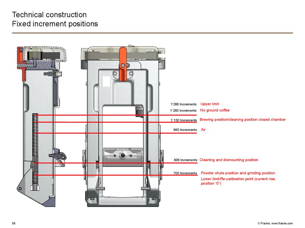
Technical constructionFixed increment positions
1’266 Increments
Upper limit
1´260 Increments
No ground coffee
1´130 Increments Brewing position/cleaning position closed chamber
980 Increments
Air
806 Increments Cleaning and dismounting position
700 Increments
Powder chute position and grinding position
Lower limit/Re-calibration point (current rise,
position “0”)
58
© Franke, www.franke.com
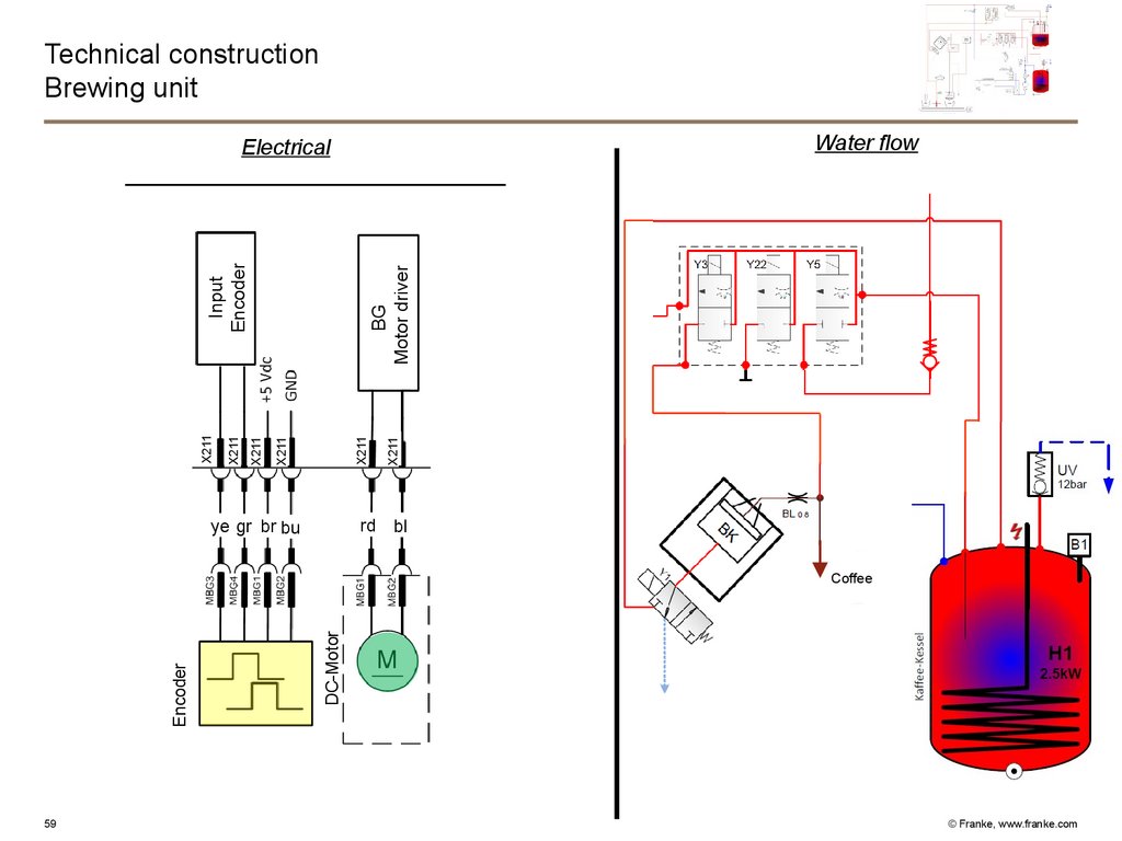
59.
Technical constructionBrewing unit
Water flow
BG
Motor driver
rd
ye gr br bu
X211
X211
X211
X211
X211
X211
Input
Encoder
Electrical
bl
Coffee
59
DC-Motor
Encoder
rt
bl
sw
© Franke, www.franke.com
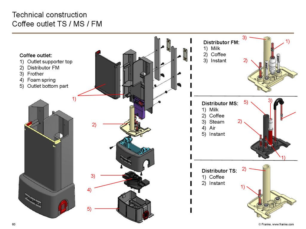
60.
Technical constructionCoffee outlet TS / MS / FM
3)
Distributor FM:
1) Milk
2) Coffee
2)
3) Instant
Coffee outlet:
1) Outlet supporter top
2) Distributor FM
3) Frother
4) Foam spring
5) Outlet bottom part
1)
2)
Distributor MS: 5)
1) Milk
2) Coffee
2)
3) Steam
4) Air
5) Instant
1)
3)
1)
3)
4)
Distributor TS: 2)
1) Coffee
2) Instant
1)
5)
60
© Franke, www.franke.com
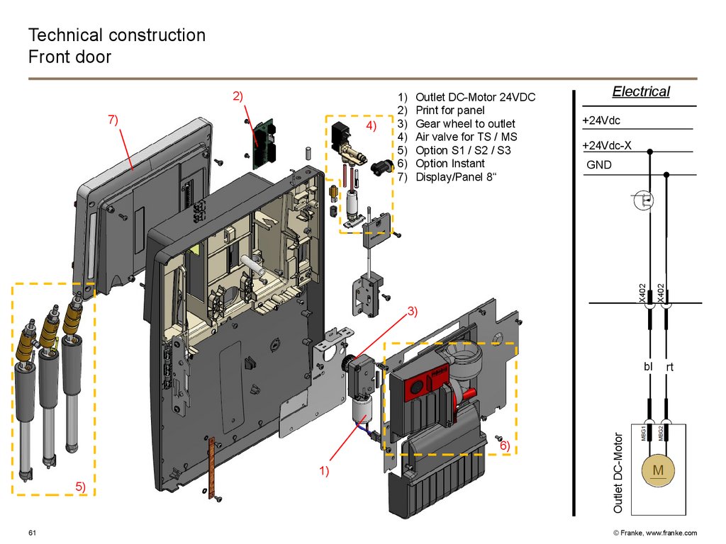
61.
Technical constructionFront door
7)
Outlet DC-Motor 24VDC
Print for panel
Gear wheel to outlet
Air valve for TS / MS
Option S1 / S2 / S3
Option Instant
Display/Panel 8“
Electrical
+24Vdc
+24Vdc-X
GND
X402
4)
1)
2)
3)
4)
5)
6)
7)
X402
2)
3)
6)
1)
5)
61
Outlet DC-Motor
bl
rt
Outlet
Motor
© Franke, www.franke.com
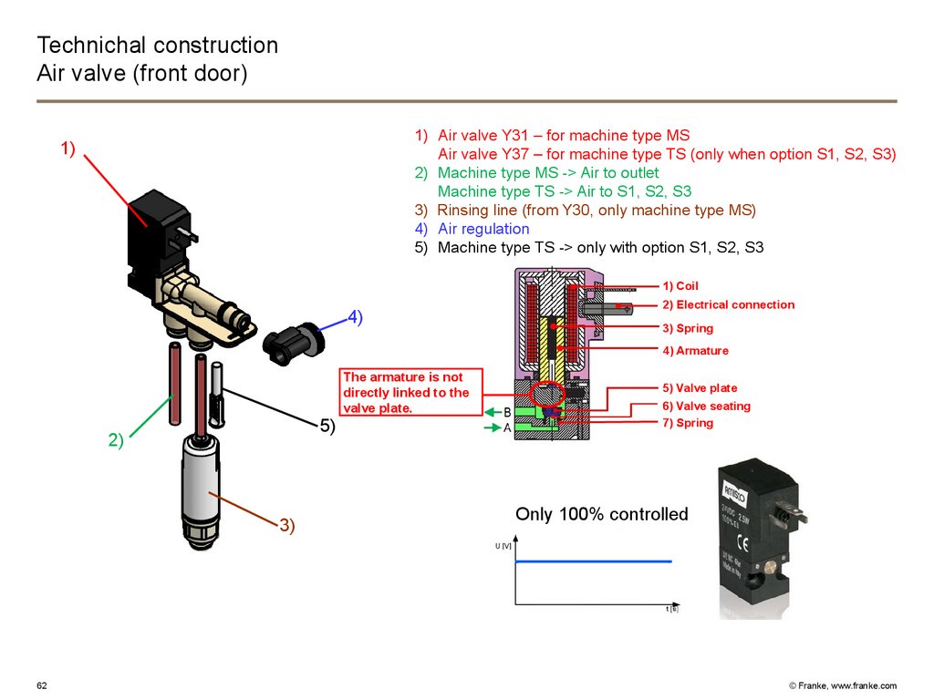
62.
Technichal constructionAir valve (front door)
1) Air valve Y31 – for machine type MS
Air valve Y37 – for machine type TS (only when option S1, S2, S3)
2) Machine type MS -> Air to outlet
Machine type TS -> Air to S1, S2, S3
3) Rinsing line (from Y30, only machine type MS)
4) Air regulation
5) Machine type TS -> only with option S1, S2, S3
1)
1) Coil
4)
2) Electrical connection
3) Spring
4) Armature
5)
2)
3)
62
The armature is not
directly linked to the
valve plate.
5) Valve plate
6) Valve seating
7) Spring
Only 100% controlled
© Franke, www.franke.com
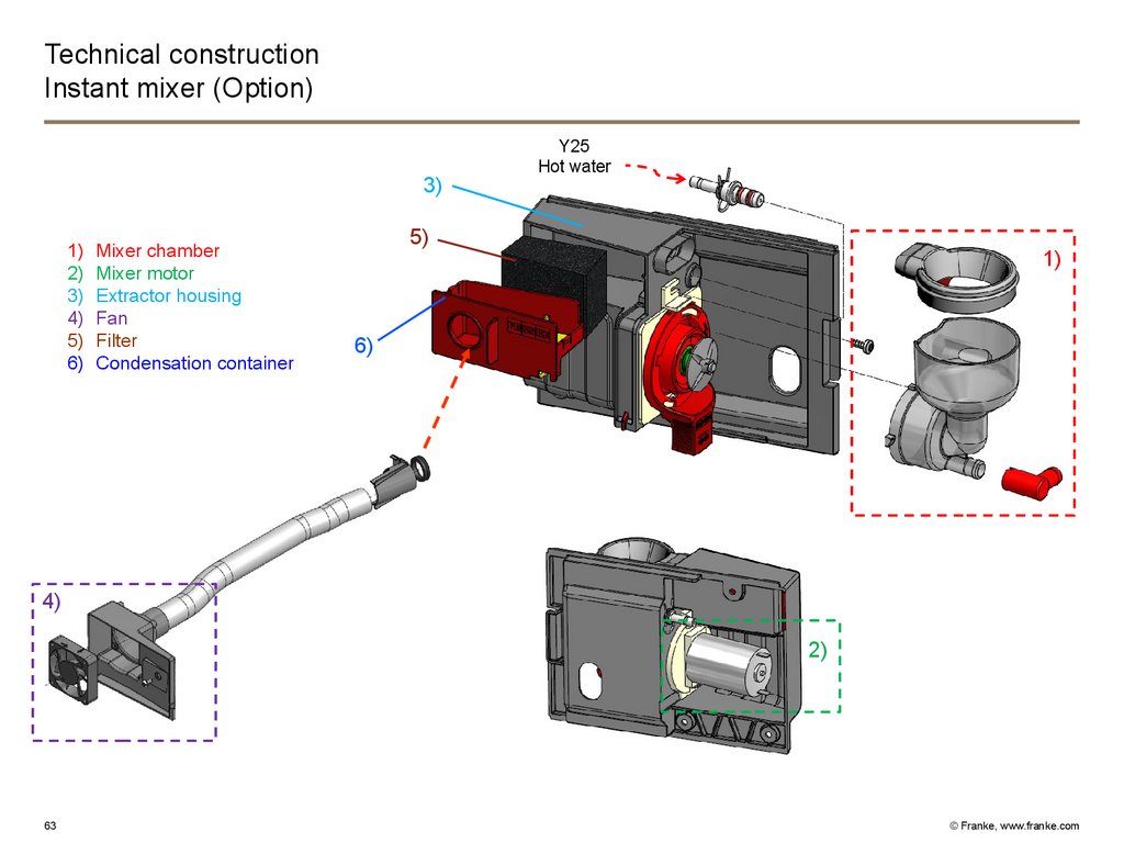
63.
Technical constructionInstant mixer (Option)
3)
1)
2)
3)
4)
5)
6)
Mixer chamber
Mixer motor
Extractor housing
Fan
Filter
Condensation container
Y25
Hot water
5)
1)
6)
4)
2)
63
© Franke, www.franke.com
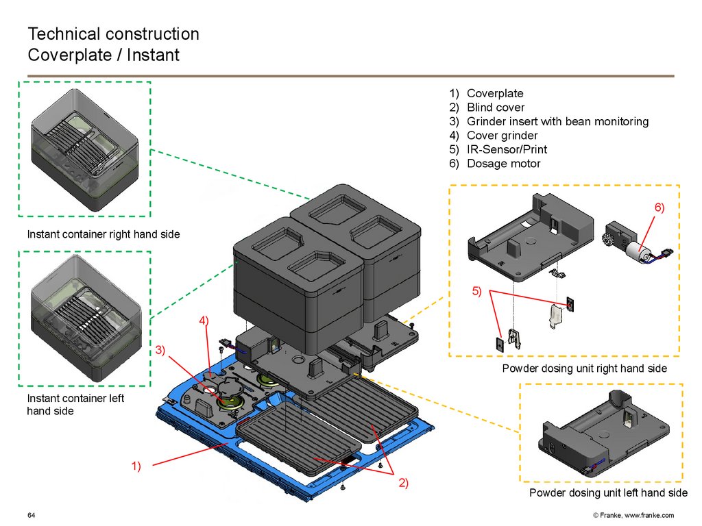
64.
Technical constructionCoverplate / Instant
1)
2)
3)
4)
5)
6)
Coverplate
Blind cover
Grinder insert with bean monitoring
Cover grinder
IR-Sensor/Print
Dosage motor
6)
Instant container right hand side
5)
4)
3)
Pulverdosierer
rechts
Powder
dosing unit right
hand side
Instant container left
hand side
1)
2)
64
Powder dosing unit left hand side
© Franke, www.franke.com
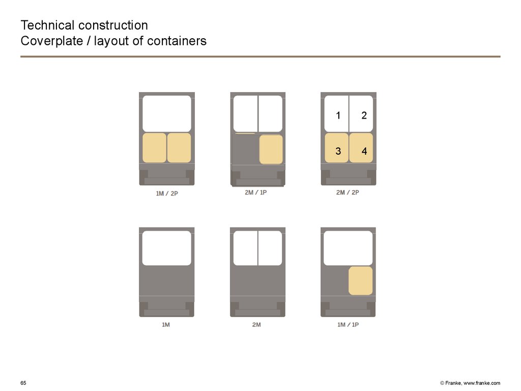
65.
Technical constructionCoverplate / layout of containers
65
1
2
3
4
© Franke, www.franke.com
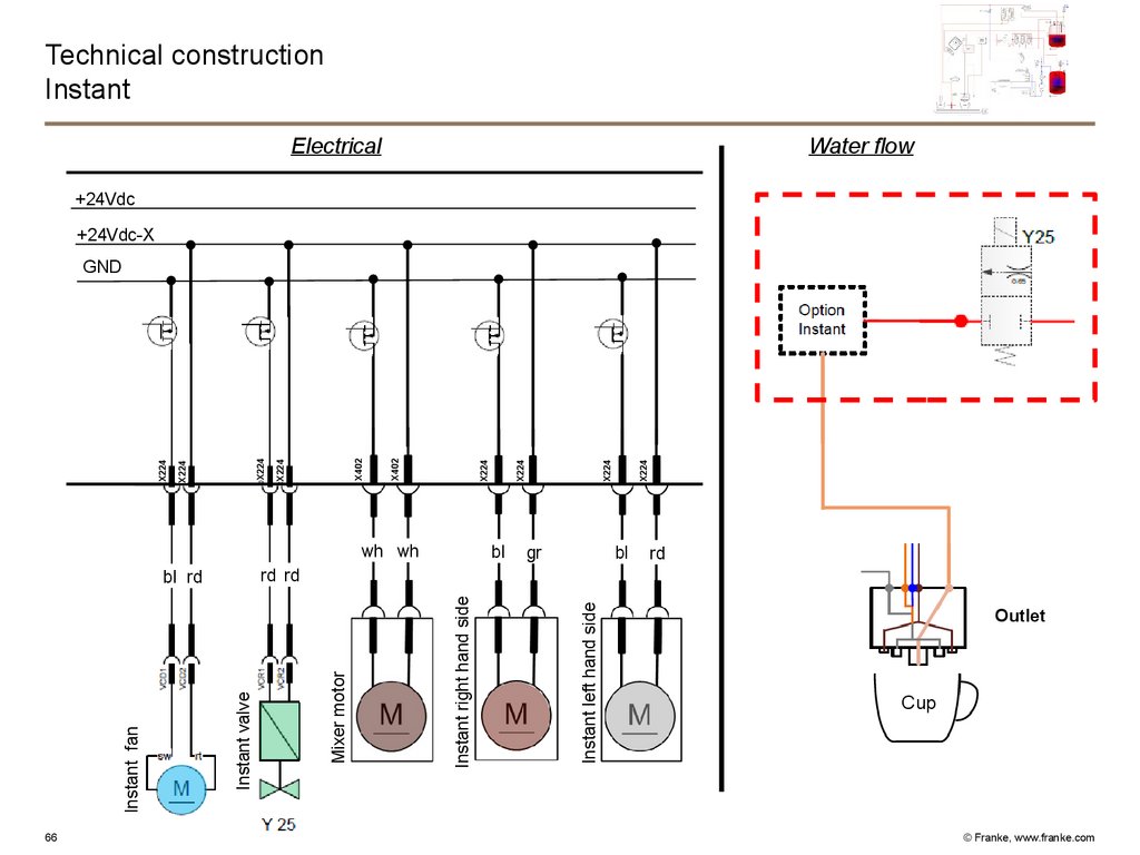
66.
Technical constructionInstant
Electrical
Water flow
+24Vdc
+24Vdc-X
wh wh
X224
X224
gr
bl
Instant left hand side
Instant right hand side
Mixer motor
Instant valve
Instant fan
bl
rd
rd rd
bl rd
66
X224
X224
X402
X402
X224
X224
X224
X224
GND
Outlet
Cup
© Franke, www.franke.com
67.
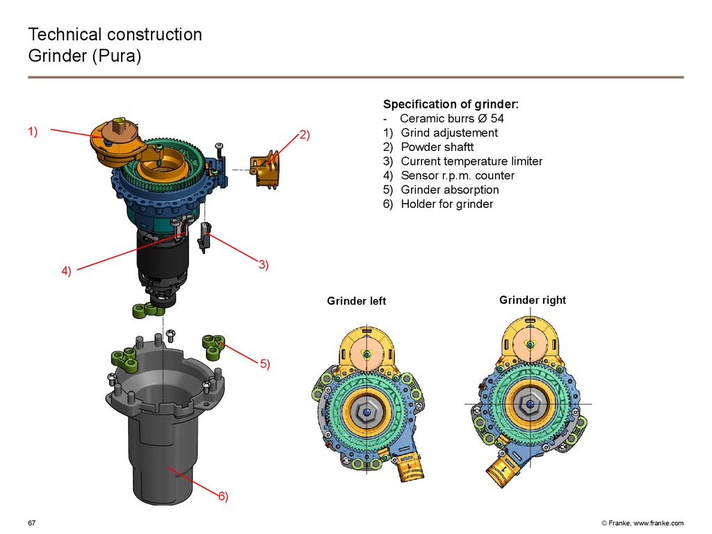
Technical constructionGrinder (Pura)
1)
Specification of grinder:
- Ceramic burrs Ø 54
1) Grind adjustement
2) Powder shaftt
3) Current temperature limiter
4) Sensor r.p.m. counter
5) Grinder absorption
6) Holder for grinder
2)
3)
4)
Grinder left
Grinder right
Mühle links
5)
6)
67
© Franke, www.franke.com
68.
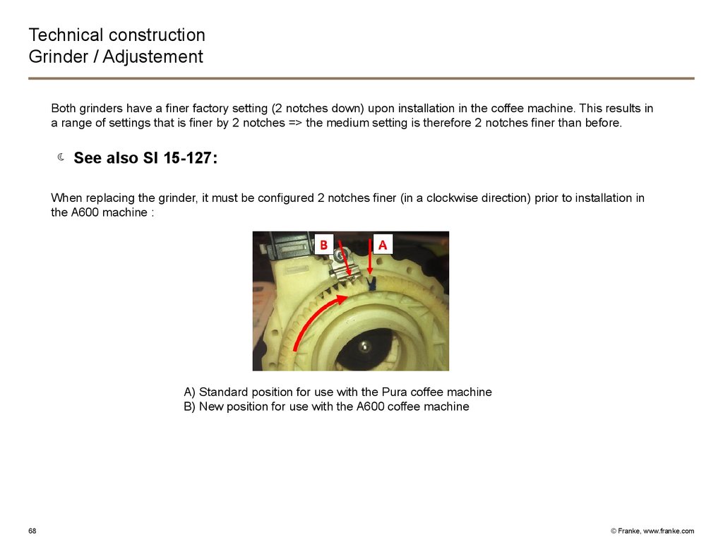
Technical constructionGrinder / Adjustement
Both grinders have a finer factory setting (2 notches down) upon installation in the coffee machine. This results in
a range of settings that is finer by 2 notches => the medium setting is therefore 2 notches finer than before.
See also SI 15-127:
When replacing the grinder, it must be configured 2 notches finer (in a clockwise direction) prior to installation in
the A600 machine :
A) Standard position for use with the Pura coffee machine
B) New position for use with the A600 coffee machine
68
© Franke, www.franke.com
69.
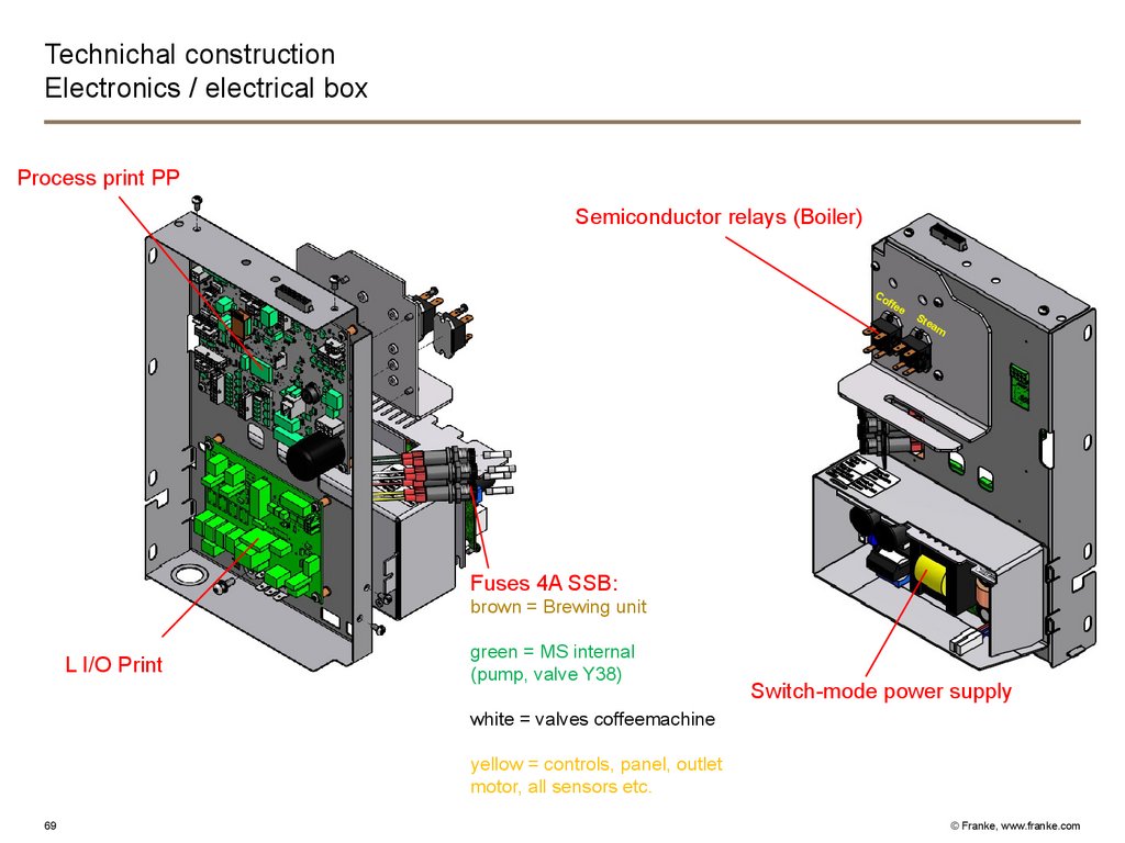
Technichal constructionElectronics / electrical box
Process print PP
Semiconductor relays (Boiler)
Co
ffe
e
Ste
a
m
Fuses 4A SSB:
brown = Brewing unit
L I/O Print
green = MS internal
(pump, valve Y38)
Switch-mode power supply
white = valves coffeemachine
yellow = controls, panel, outlet
motor, all sensors etc.
69
© Franke, www.franke.com
70.
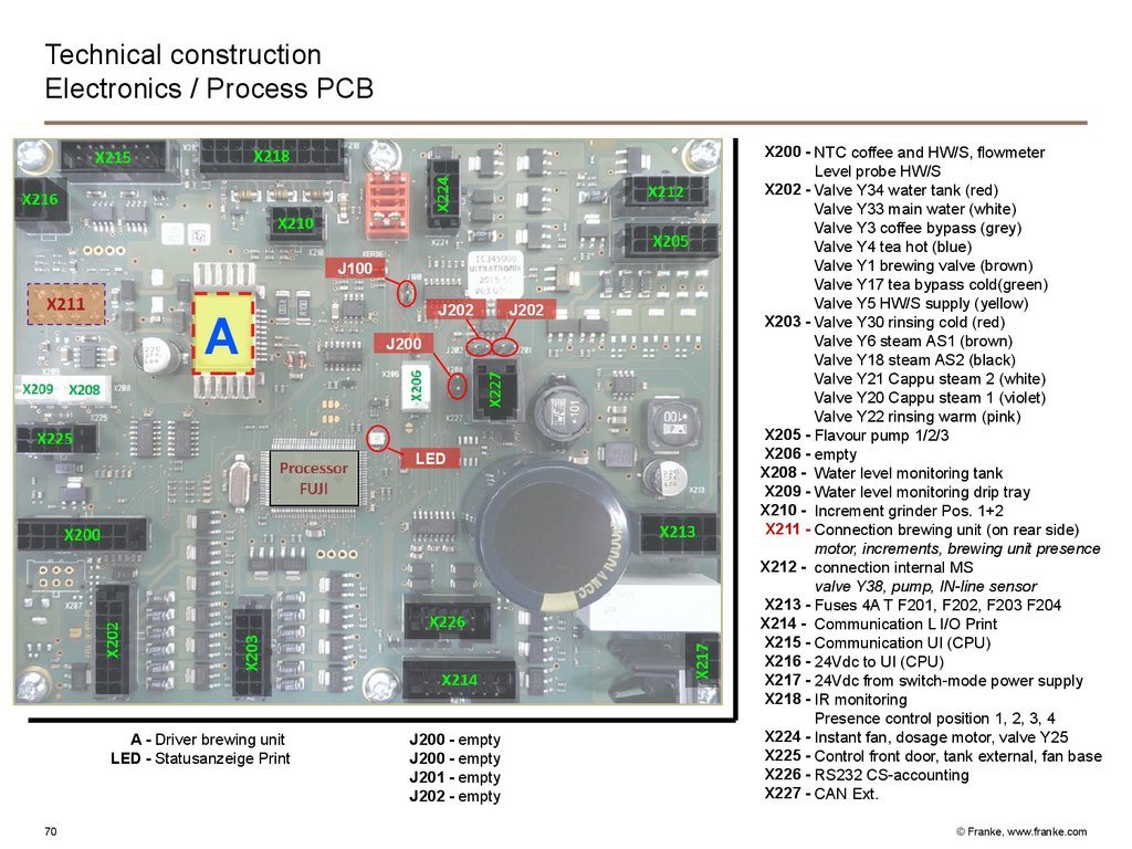
Technical constructionElectronics / Process PCB
J100
A
J202
J200
LED
A - Driver brewing unit
LED - Statusanzeige Print
70
J200 - empty
J200 - empty
J201 - empty
J202 - empty
J202
X200 - NTC coffee and HW/S, flowmeter
Level probe HW/S
X202 - Valve Y34 water tank (red)
Valve Y33 main water (white)
Valve Y3 coffee bypass (grey)
Valve Y4 tea hot (blue)
Valve Y1 brewing valve (brown)
Valve Y17 tea bypass cold(green)
Valve Y5 HW/S supply (yellow)
X203 - Valve Y30 rinsing cold (red)
Valve Y6 steam AS1 (brown)
Valve Y18 steam AS2 (black)
Valve Y21 Cappu steam 2 (white)
Valve Y20 Cappu steam 1 (violet)
Valve Y22 rinsing warm (pink)
X205 - Flavour pump 1/2/3
X206 - empty
X208 - Water level monitoring tank
X209 - Water level monitoring drip tray
X210 - Increment grinder Pos. 1+2
X211 - Connection brewing unit (on rear side)
motor, increments, brewing unit presence
X212 - connection internal MS
valve Y38, pump, IN-line sensor
X213 - Fuses 4A T F201, F202, F203 F204
X214 - Communication L I/O Print
X215 - Communication UI (CPU)
X216 - 24Vdc to UI (CPU)
X217 - 24Vdc from switch-mode power supply
X218 - IR monitoring
Presence control position 1, 2, 3, 4
X224 - Instant fan, dosage motor, valve Y25
X225 - Control front door, tank external, fan base
X226 - RS232 CS-accounting
X227 - CAN Ext.
© Franke, www.franke.com
71.
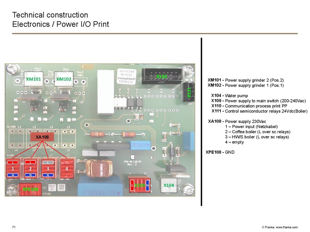
Technical constructionElectronics / Power I/O Print
XM101 - Power supply grinder 2 (Pos.2)
XM102 - Power supply grinder 1 (Pos.1)
X104 - Water pump
X109 - Power supply to main switch (200-240Vac)
X110 - Communication process print PP
X111 - Control semiconductor relays 24Vdc(Boiler)
XA108
XA108 - Power supply 230Vac
1 – Power input (Netzkabel)
2 – Coffee boiler (L over sc relays)
3 – HW/S boiler (L over sc relays)
4 – empty
XPE108 - GND
71
© Franke, www.franke.com
72.
Technical constructionElectronics / semiconductor relays (coffee and HW/S boiler)
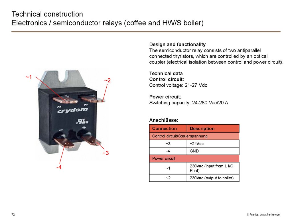
Design and functionality
The semiconductor relay consists of two antiparallel
connected thyristors, which are controlled by an optical
coupler (electrical isolation between control and power circuit).
~1
~2
Technical data
Control circuit:
Control voltage: 21-27 Vdc
Power circuit:
Switching capacity: 24-280 Vac/20 A
Anschlüsse:
Connection
Description
Control circuit/Steuerspannung
+3
+3
+24Vdc
-4
GND
Power circuit
-4
72
~1
230Vac (input from L I/O
Print)
~2
230Vac (output to boiler)
© Franke, www.franke.com
73.
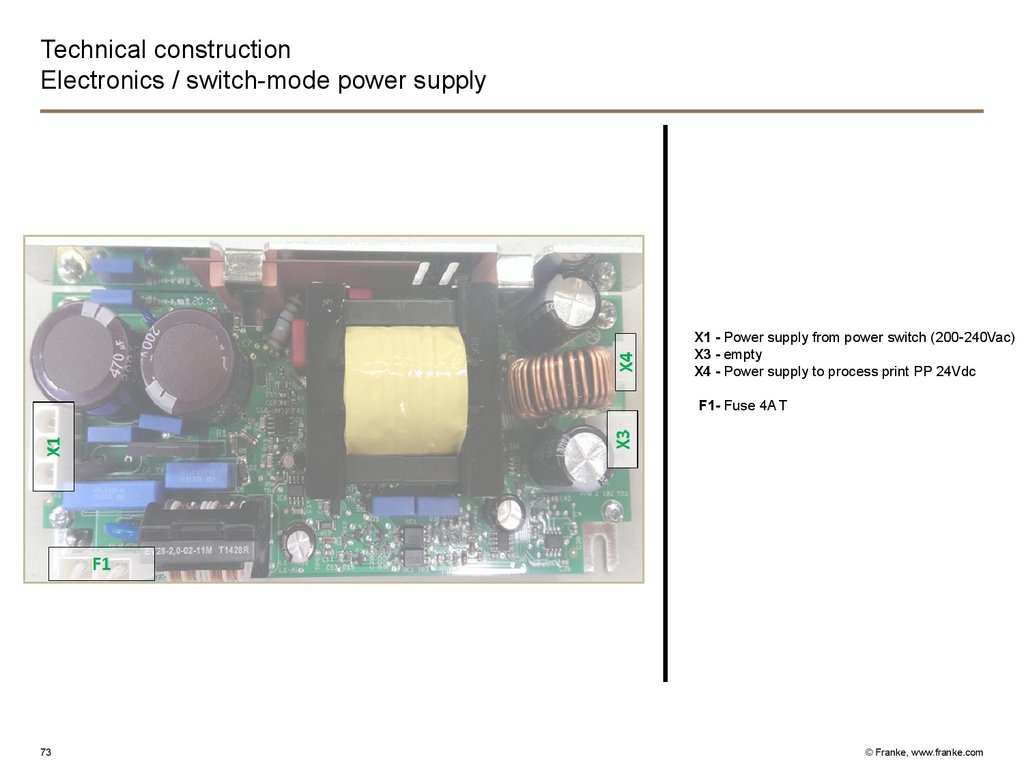
Technical constructionElectronics / switch-mode power supply
X1 - Power supply from power switch (200-240Vac)
X3 - empty
X4 - Power supply to process print PP 24Vdc
F1- Fuse 4A T
73
© Franke, www.franke.com
74.
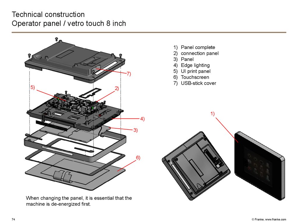
Technical constructionOperator panel / vetro touch 8 inch
1)
2)
3)
4)
5)
6)
7)
7)
5)
2)
4)
Panel complete
connection panel
Panel
Edge lighting
UI print panel
Touchscreen
USB-stick cover
1)
3)
6)
When changing the panel, it is essential that the
machine is de-energized first.
74
© Franke, www.franke.com
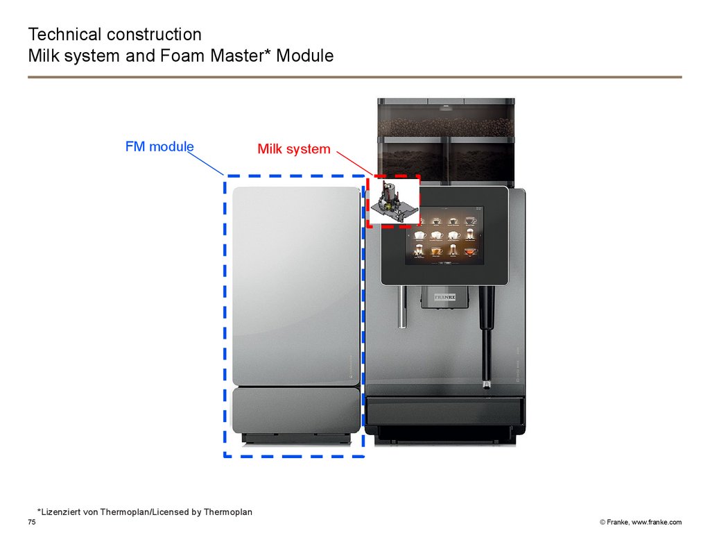
75.
Technical constructionMilk system and Foam Master* Module
FM module
Milk system
*Lizenziert von Thermoplan/Licensed by Thermoplan
75
© Franke, www.franke.com
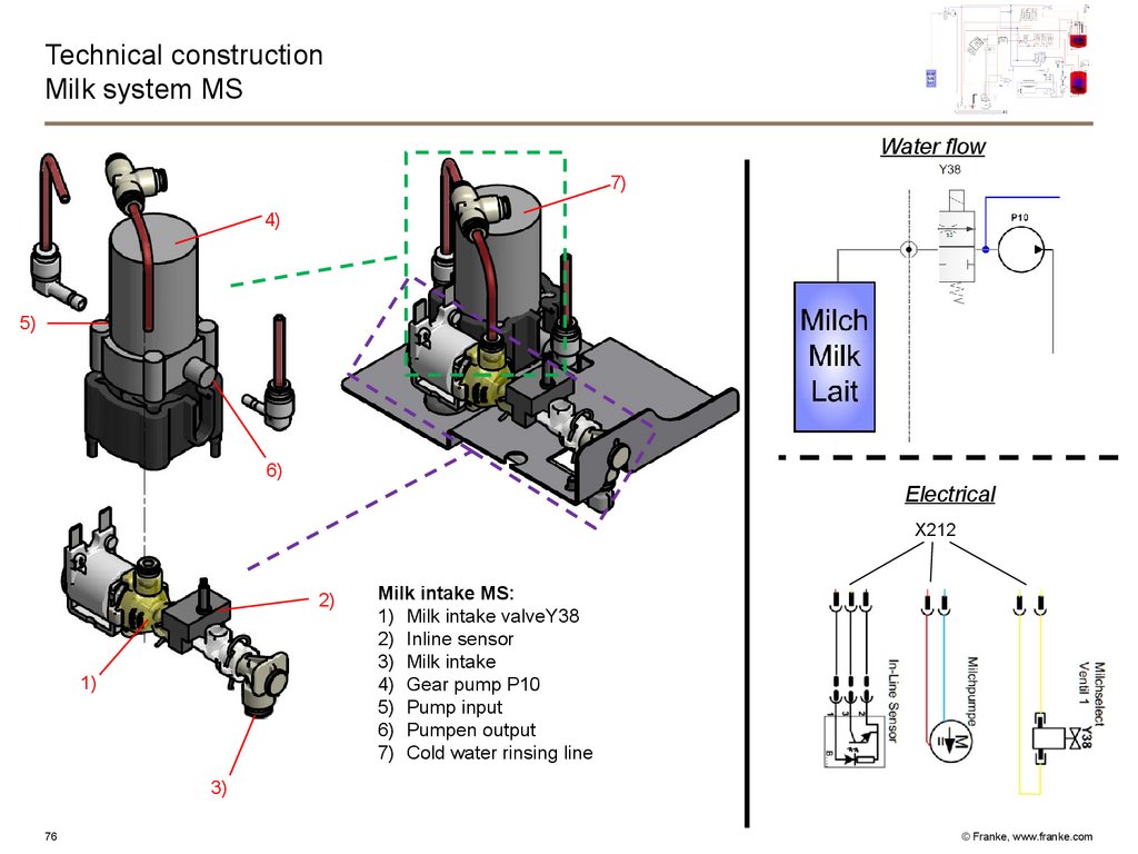
76.
Technical constructionMilk system MS
Water flow
7)
4)
5)
6)
Electrical
X212
2)
1)
Milk intake MS:
1) Milk intake valveY38
2) Inline sensor
3) Milk intake
4) Gear pump P10
5) Pump input
6) Pumpen output
7) Cold water rinsing line
3)
76
© Franke, www.franke.com
77.
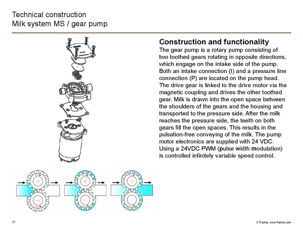
Technical constructionMilk system MS / gear pump
Construction and functionality
The gear pump is a rotary pump consisting of
two toothed gears rotating in opposite directions,
which engage on the intake side of the pump.
Both an intake connection (I) and a pressure line
connection (P) are located on the pump head.
The drive gear is linked to the drive motor via the
magnetic coupling and drives the other toothed
gear. Milk is drawn into the open space between
the shoulders of the gears and the housing and
transported to the pressure side. After the milk
reaches the pressure side, the teeth on both
gears fill the open spaces. This results in the
pulsation-free conveying of the milk. The pump
motor electronics are supplied with 24 VDC.
Using a 24VDC PWM (pulse width modulation)
is controlled infinitely variable speed control.
77
© Franke, www.franke.com
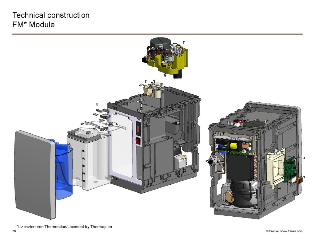
78.
Technical constructionFM* Module
*Lizenziert von Thermoplan/Licensed by Thermoplan
78
© Franke, www.franke.com
79.
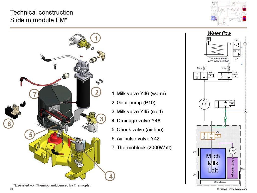
Technical constructionSlide in module FM*
Water flow
1
7
2
1. Milk valve Y46 (warm)
2. Gear pump (P10)
3. Milk valve Y45 (cold)
3
6
5
4. Drainage valve Y48
5. Check valve (air line)
6. Air pulse valve Y42
7. Thermoblock (2000Watt)
4
*Lizenziert von Thermoplan/Licensed by Thermoplan
79
© Franke, www.franke.com
80.
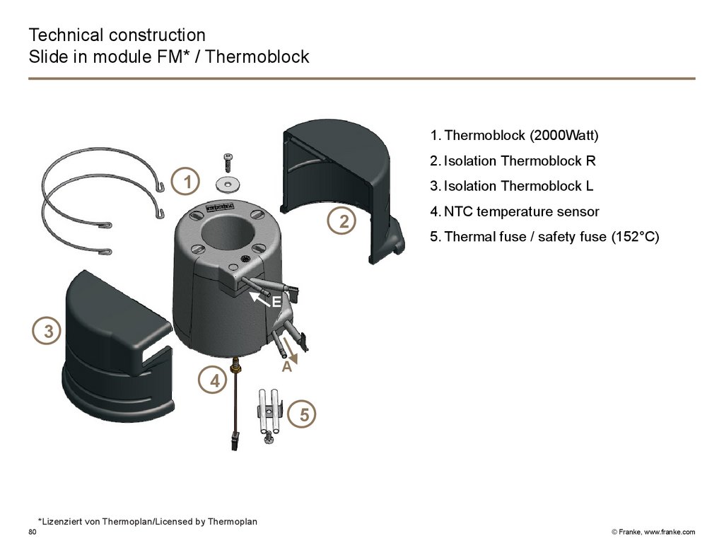
Technical constructionSlide in module FM* / Thermoblock
1. Thermoblock (2000Watt)
2. Isolation Thermoblock R
1
3. Isolation Thermoblock L
2
4. NTC temperature sensor
5. Thermal fuse / safety fuse (152°C)
E
3
4
A
5
*Lizenziert von Thermoplan/Licensed by Thermoplan
80
© Franke, www.franke.com
81.
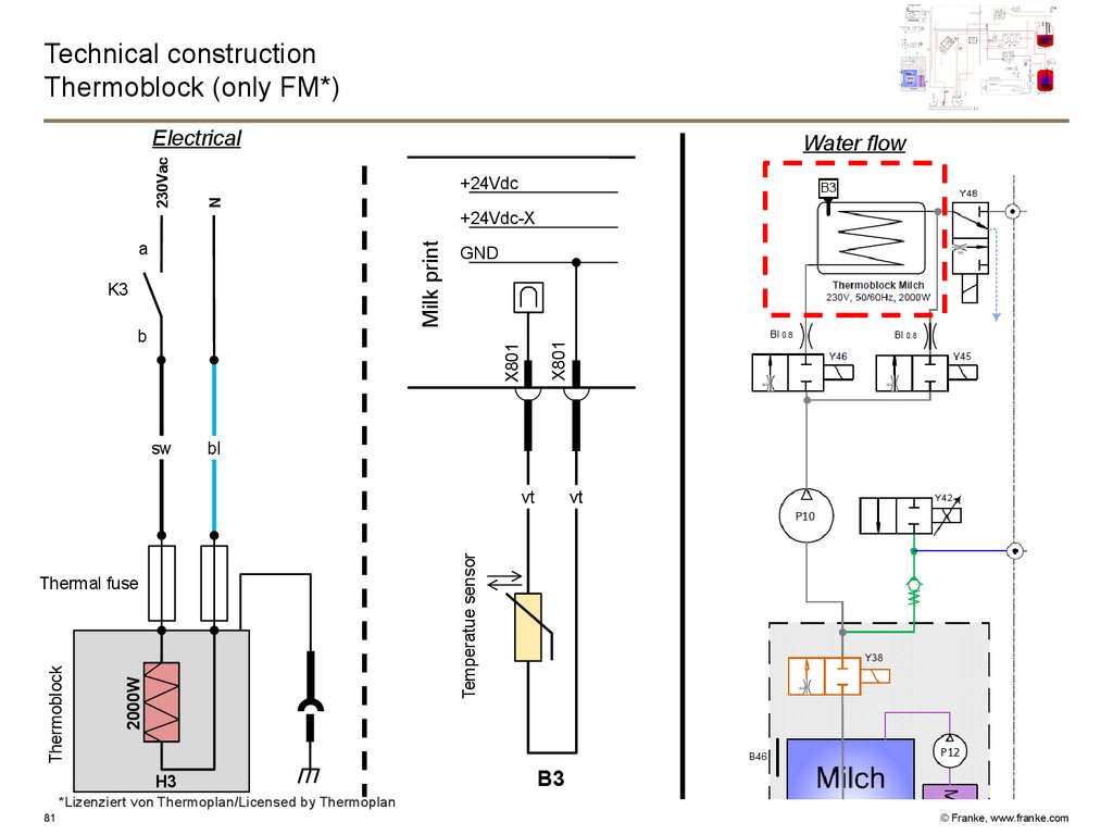
Technical constructionThermoblock (only FM*)
Water flow
+24Vdc
N
+24Vdc-X
Milk print
a
K3
X801
b
GND
X801
230Vac
Electrical
sw
bl
2000W
Thermal fuse
Thermoblock
vt
Temperatue sensor
vt
H3
B3
*Lizenziert von Thermoplan/Licensed by Thermoplan
81
© Franke, www.franke.com
82.
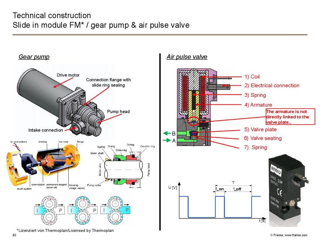
Technical constructionSlide in module FM* / gear pump & air pulse valve
Gear pump
Air pulse valve
Drive motor
1) Coil
Connection flange with
slide ring sealing
2) Electrical connection
3) Spring
4) Armature
Pump head
Intake connection
The armature is not
directly linked to the
valve plate..
5) Valve plate
B
A
6) Valve seating
7) Spring
on
I
P
I
P
I
off
P
*Lizenziert von Thermoplan/Licensed by Thermoplan
82
© Franke, www.franke.com
83.
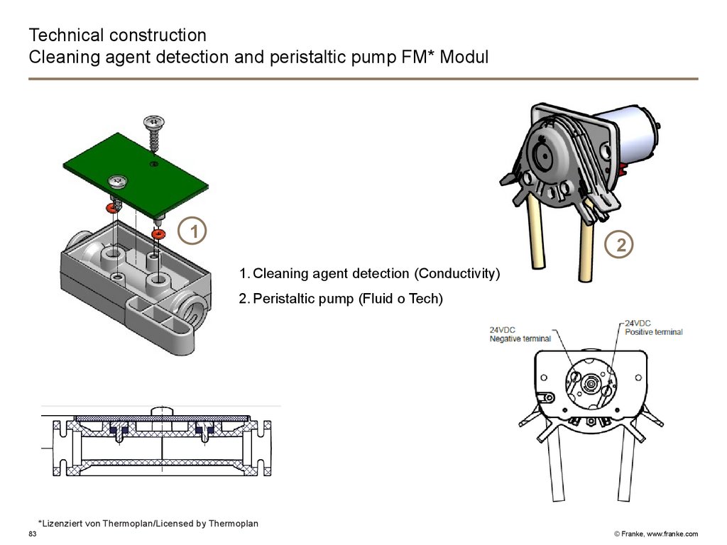
Technical constructionCleaning agent detection and peristaltic pump FM* Modul
1
2
1. Cleaning agent detection (Conductivity)
2. Peristaltic pump (Fluid o Tech)
*Lizenziert von Thermoplan/Licensed by Thermoplan
83
© Franke, www.franke.com
84.
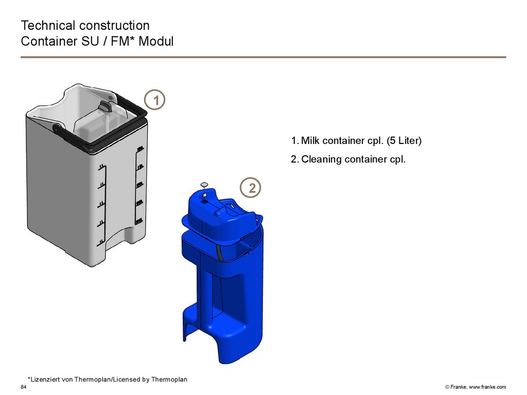
Technical constructionContainer SU / FM* Modul
1
1. Milk container cpl. (5 Liter)
2. Cleaning container cpl.
2
*Lizenziert von Thermoplan/Licensed by Thermoplan
84
© Franke, www.franke.com
85.
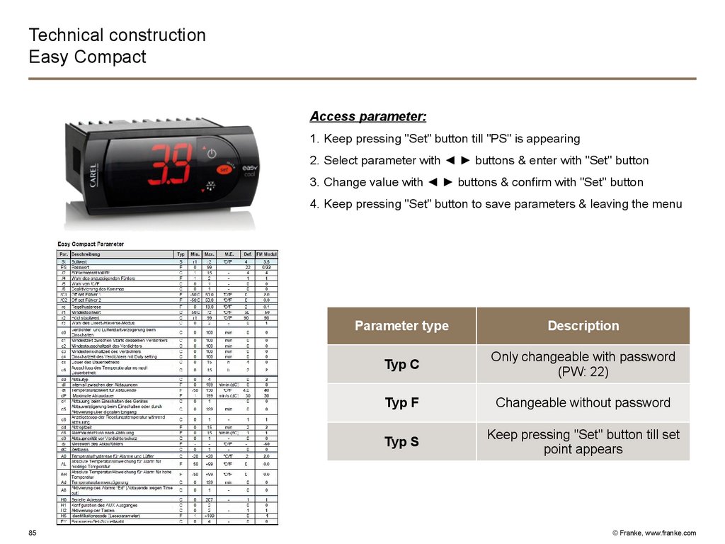
Technical constructionEasy Compact
Access parameter:
1. Keep pressing "Set" button till "PS" is appearing
2. Select parameter with ◄ ► buttons & enter with "Set" button
3. Change value with ◄ ► buttons & confirm with "Set" button
4. Keep pressing "Set" button to save parameters & leaving the menu
85
Parameter type
Description
Typ C
Only changeable with password
(PW: 22)
Typ F
Changeable without password
Typ S
Keep pressing "Set" button till set
point appears
© Franke, www.franke.com
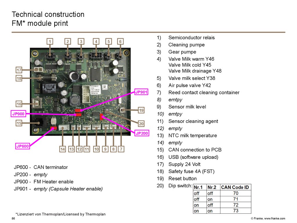
86.
Technical constructionFM* module print
1
2
3
4
5
1)
2)
3)
4)
6
17
18
JP901
16
19
JP900
15
20
JP200
JP600
JP600 JP200 JP900 JP901 -
14
13 12 11
10
9
CAN terminator
empty
FM Heater enable
empty (Capsule Heater enable)
8
7
5)
6)
7)
8)
9)
10)
11)
12)
13)
14)
15)
16)
17)
18)
19)
20)
Semiconductor relais
Cleaning pumpe
Gear pumpe
Valve Milk warm Y46
Valve Milk cold Y45
Valve Milk drainage Y48
Valve milk select Y38
Air pulse valve Y42
Reed contact cleaning container
emtpy
Sensor milk level
emtpy
Sensor cleaning agent
empty
NTC milk temperature
empty
CAN connection to PCB
USB (software upload)
Supply 24 Volt
Safety fuse 4A (FST)
Reset button
Dip switch:
*Lizenziert von Thermoplan/Licensed by Thermoplan
86
© Franke, www.franke.com
87.
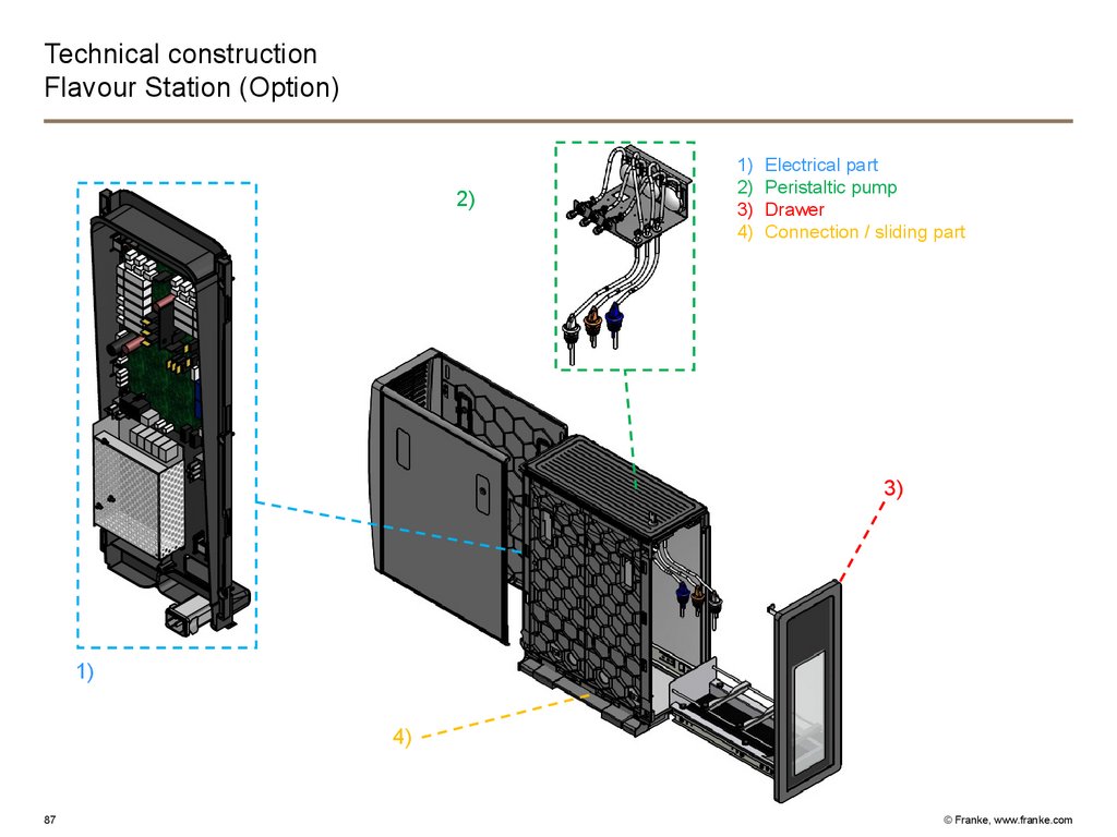
Technical constructionFlavour Station (Option)
2)
1)
2)
3)
4)
Electrical part
Peristaltic pump
Drawer
Connection / sliding part
3)
1)
4)
87
© Franke, www.franke.com
88.
Technical constructionFlavour Station / electrical part
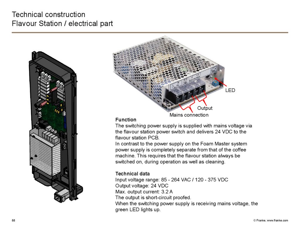
LED
Output
Mains connection
Function
The switching power supply is supplied with mains voltage via
the flavour station power switch and delivers 24 VDC to the
flavour station PCB.
In contrast to the power supply on the Foam Master system
power supply is completely separate from that of the coffee
machine. This requires that the flavour station always be
switched on, during operation as well as cleaning.
Technical data
Input voltage range: 85 - 264 VAC / 120 - 375 VDC
Output voltage: 24 VDC
Max. output current: 3.2 A
The output is short-circuit proofed.
When the switching power supply is receiving mains voltage, the
green LED lights up.
88
© Franke, www.franke.com
89.
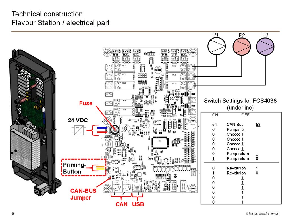
Technical constructionFlavour Station / electrical part
P1
Switch Settings for FCS4038
(underline)
Fuse
ON
24 VDC
PrimingButton
CAN-BUS
Jumper
CAN USB
89
P3
P2
OFF
54
6
0
0
0
0
0
1
CAN Bus
Pumps 3
Chocco 1
Chocco 1
Chocco 1
Chocco 1
Pump return
Pump return
53
0
1
0
0
0
0
0
0
Revolution
Revolution
1
1
1
1
1
1
1
0
1
0
© Franke, www.franke.com
90.
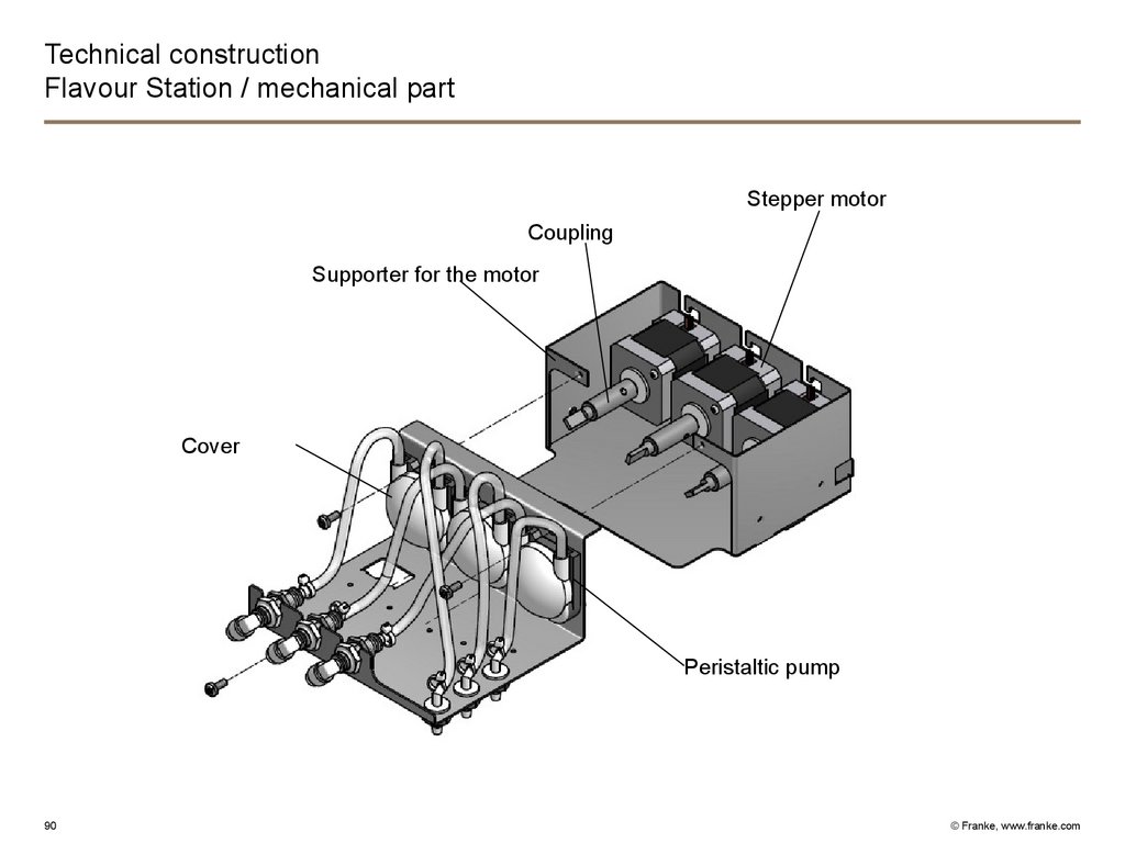
Technical constructionFlavour Station / mechanical part
Stepper motor
Coupling
Supporter for the motor
Cover
Peristaltic pump
90
© Franke, www.franke.com
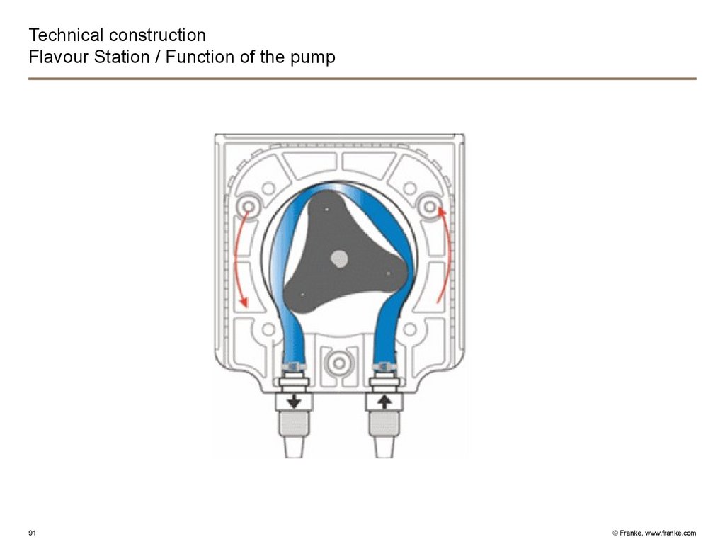
91.
Technical constructionFlavour Station / Function of the pump
91
© Franke, www.franke.com
92.
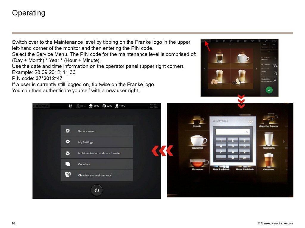
OperatingSwitch over to the Maintenance level by tipping on the Franke logo in the upper
left-hand corner of the monitor and then entering the PIN code.
Select the Service Menu. The PIN code for the maintenance level is comprised of:
(Day + Month) * Year * (Hour + Minute).
Use the date and time information on the operator panel (upper right corner).
Example: 28.09.2012; 11:36
PIN code: 37*2012*47
If a user is currently still logged on, tip twice on the Franke logo.
You can then authenticate yourself with a new user right.
92
© Franke, www.franke.com
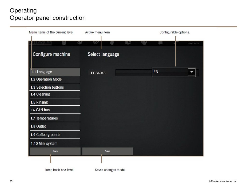
93.
OperatingOperator panel construction
FCS4043
93
© Franke, www.franke.com
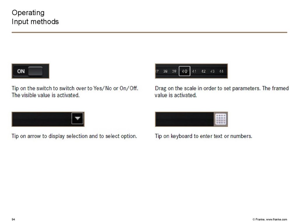
94.
OperatingInput methods
94
© Franke, www.franke.com
95.
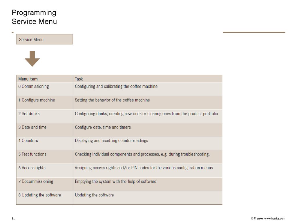
ProgrammingService Menu
95
© Franke, www.franke.com
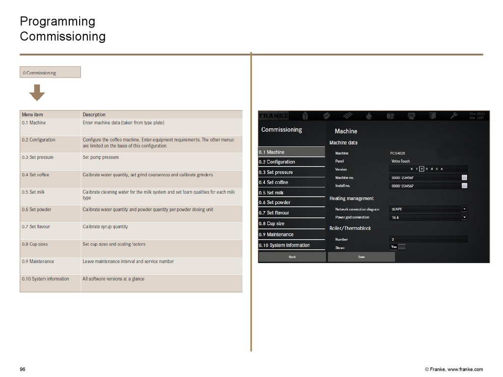
96.
ProgrammingCommissioning
FCS4026
96
© Franke, www.franke.com
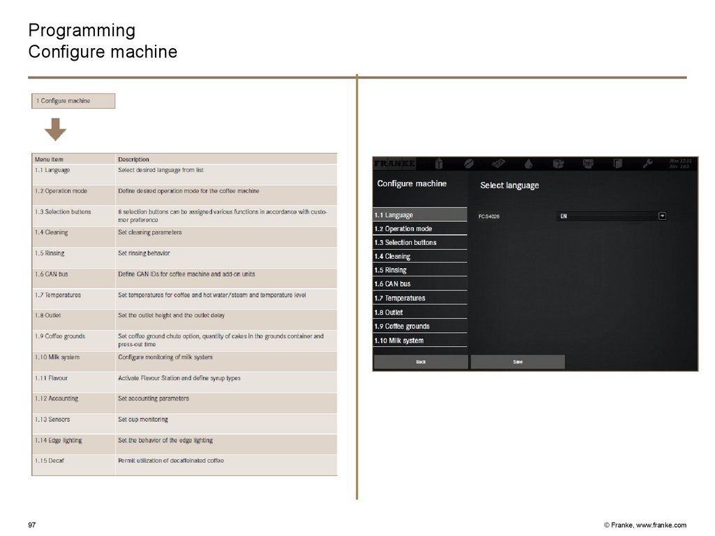
97.
ProgrammingConfigure machine
FCS4026
97
© Franke, www.franke.com
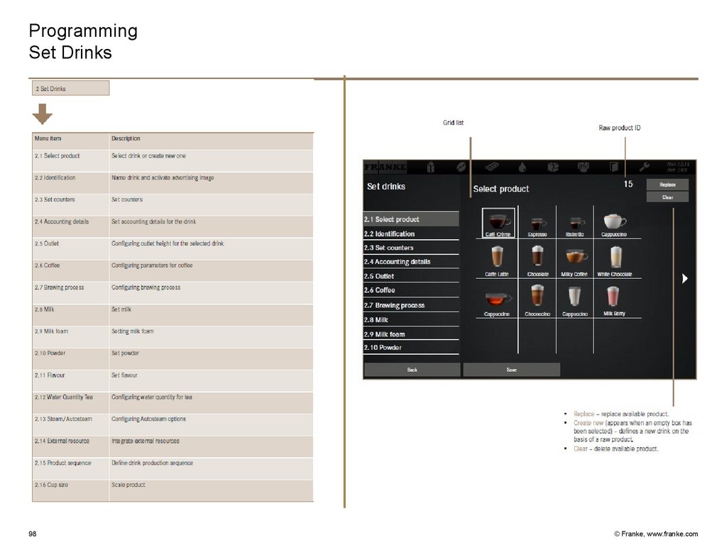
98.
ProgrammingSet Drinks
98
© Franke, www.franke.com
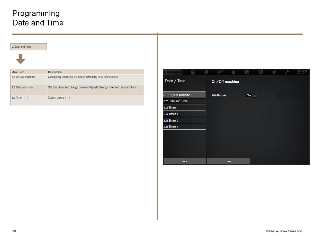
99.
ProgrammingDate and Time
99
© Franke, www.franke.com
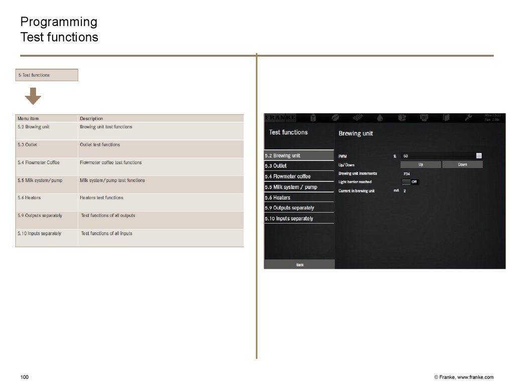
100.
ProgrammingTest functions
100
© Franke, www.franke.com
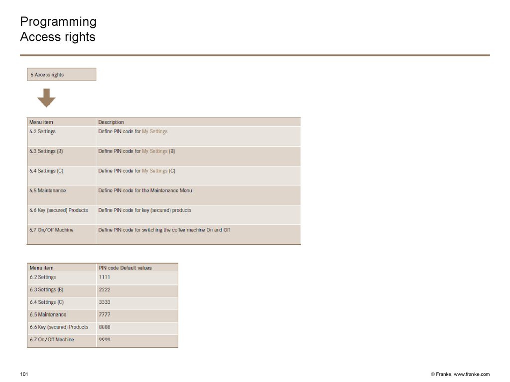
101.
ProgrammingAccess rights
101
© Franke, www.franke.com
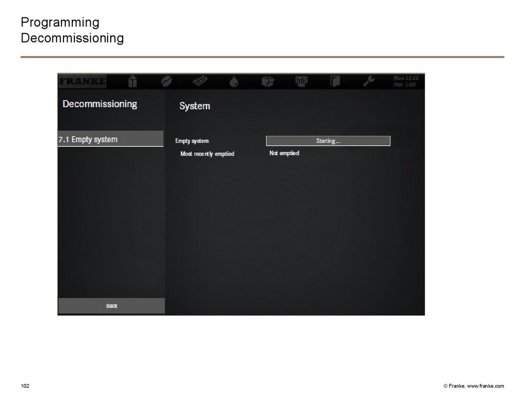
102.
ProgrammingDecommissioning
102
© Franke, www.franke.com
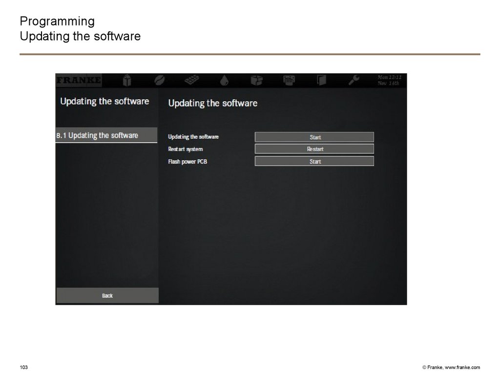
103.
ProgrammingUpdating the software
103
© Franke, www.franke.com
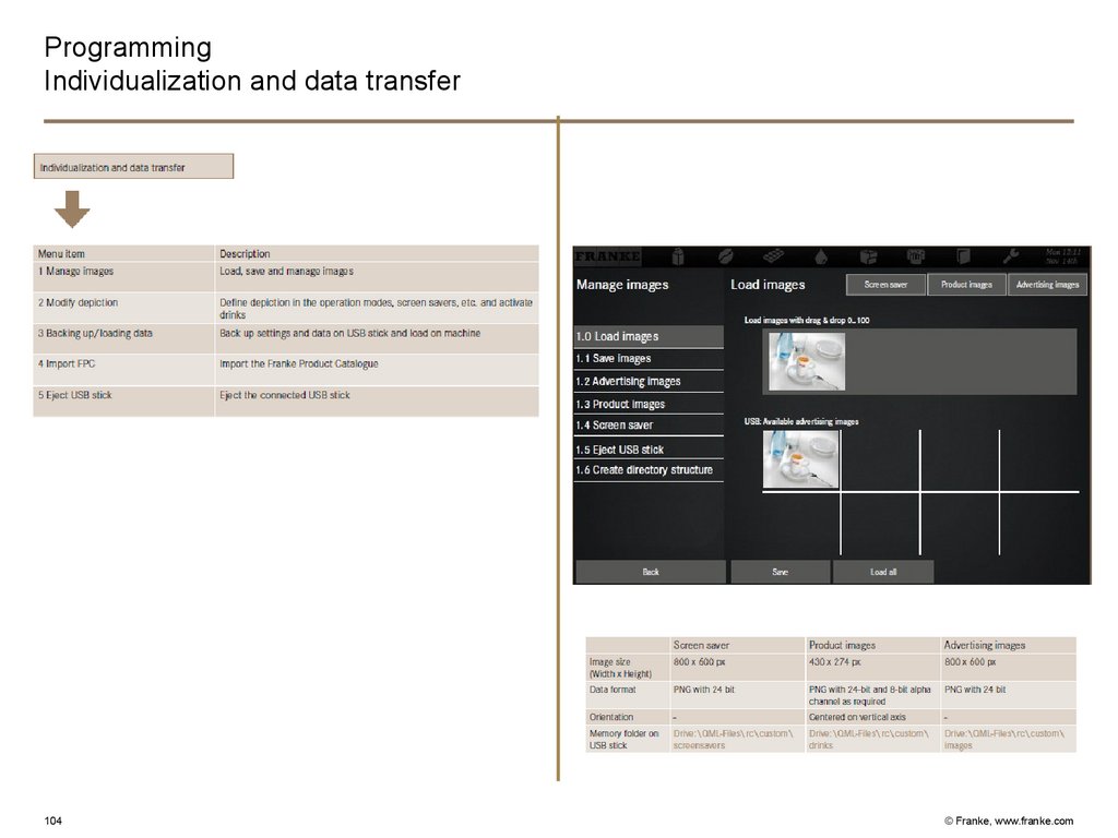
104.
ProgrammingIndividualization and data transfer
104
© Franke, www.franke.com
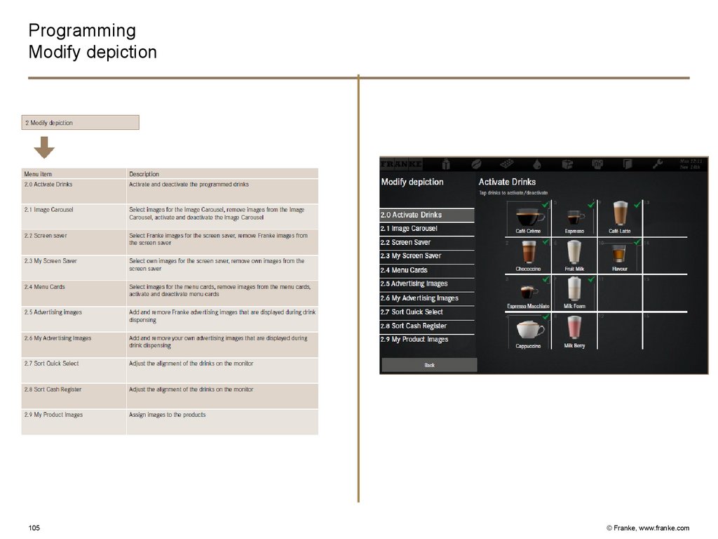
105.
ProgrammingModify depiction
105
© Franke, www.franke.com
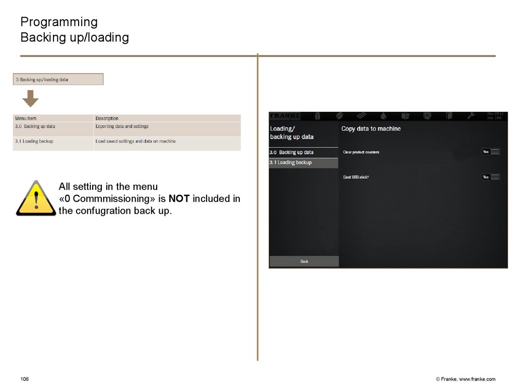
106.
ProgrammingBacking up/loading
All setting in the menu
«0 Commmissioning» is NOT included in
the confugration back up.
106
© Franke, www.franke.com
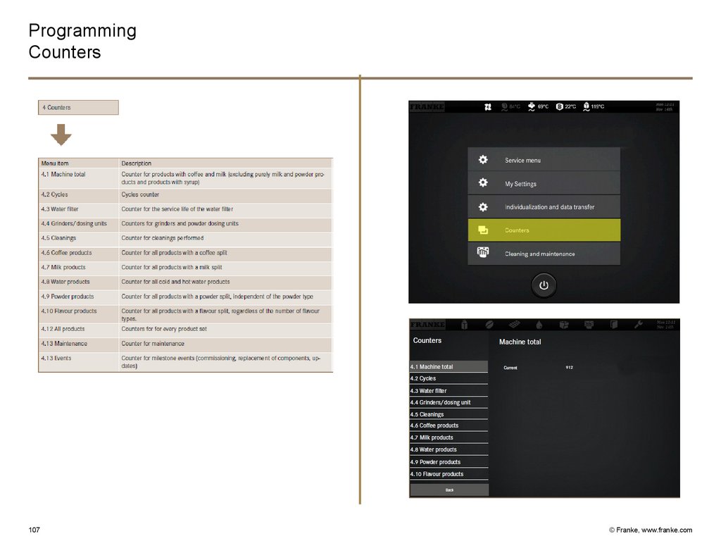
107.
ProgrammingCounters
107
© Franke, www.franke.com
108.
A600− Accessibility components
− Commissioning
− Product adjustement
− Trouble shooting
− Cleaning
108
© Franke, www.franke.com
109.
Questions?QUESTIONS?
109
© Franke, www.franke.com
110.
Aarburg, 13/10/20THANK YOU FOR
YOUR ATTENTION
Contact:
Przemyslaw Malina
Franke Kaffeemaschinen AG
CH-4663 Aarburg
Switzerland
Phone: +41 62 787 3413
przemyslaw.malina@franke.com
www.franke.com
110
© Franke, www.franke.com