


 industry
Similar presentations:


ACTYON Service Training. Engine : D20DT / D27DT. Engine General
1.
ACTYONService Training
Engine : D20DT / D27DT
Subject : Engine General
Date : March .13 . 2006
Instructor : Brian Cho
2.
ContentsD20DT Engine General
Removal & Installation
Turbo Charger (VGT)
Diagnosis
3.
D20DT Engine General3
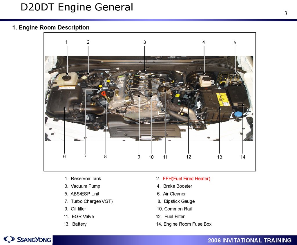
1. Engine Room Description
1
6
2
7
3
8
9
4
10
11
5
12
13
1. Reservoir Tank
2. FFH(Fuel Fired Heater)
3. Vacuum Pump
4. Brake Booster
5. ABS/ESP Unit
6. Air Cleaner
7. Turbo Charger(VGT)
8. Dipstick Gauge
9. Oil filler
10. Common Rail
11. EGR Valve
12. Fuel Filter
13. Battery
14. Engine Room Fuse Box
1
14
2006 INVITATIONAL TRAINING
4.
D20DT Engine General4
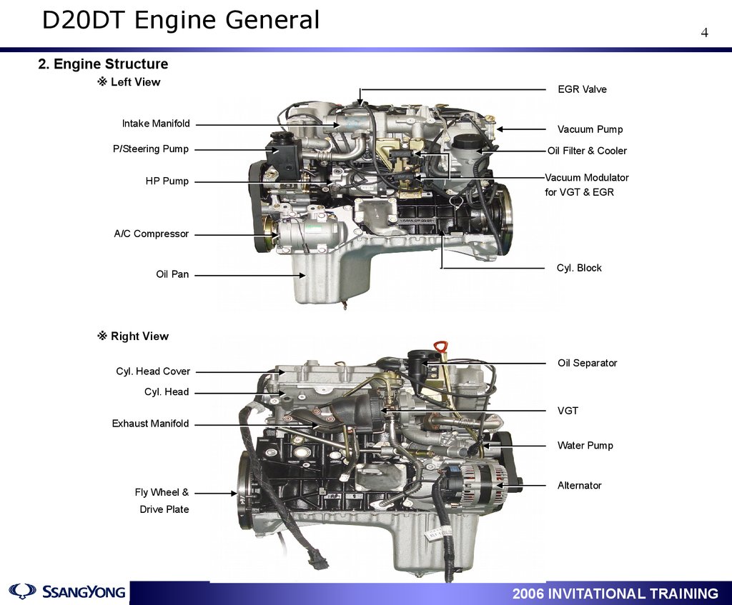
2. Engine Structure
※ Left View
EGR Valve
Intake Manifold
Vacuum Pump
P/Steering Pump
Oil Filter & Cooler
HP Pump
Vacuum Modulator
for VGT & EGR
A/C Compressor
Cyl. Block
Oil Pan
※ Right View
Oil Separator
Cyl. Head Cover
Cyl. Head
VGT
Exhaust Manifold
Water Pump
Alternator
Fly Wheel &
Drive Plate
1
2006 INVITATIONAL TRAINING
5.
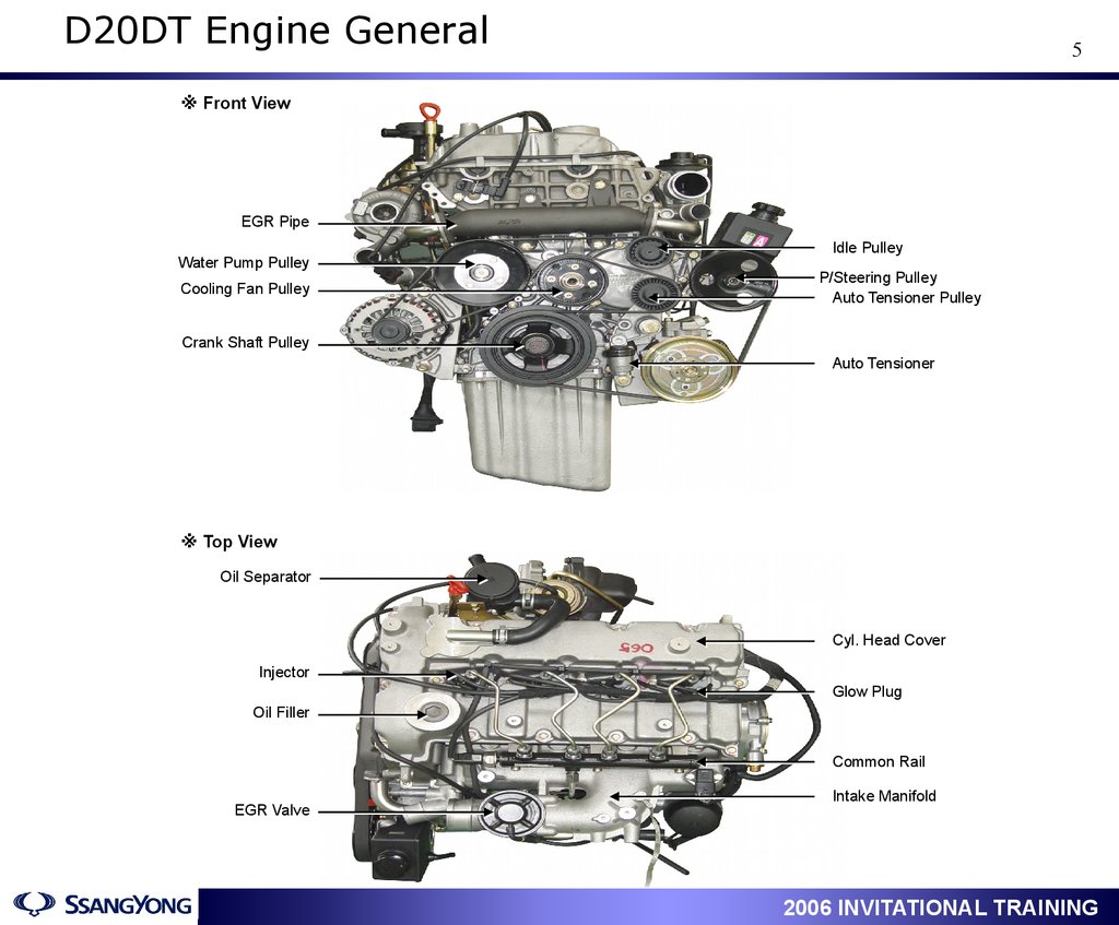
D20DT Engine General5
※ Front View
EGR Pipe
Idle Pulley
Water Pump Pulley
P/Steering Pulley
Auto Tensioner Pulley
Cooling Fan Pulley
Crank Shaft Pulley
Auto Tensioner
※ Top View
Oil Separator
Cyl. Head Cover
Injector
Glow Plug
Oil Filler
Common Rail
Intake Manifold
EGR Valve
1
2006 INVITATIONAL TRAINING
6.
D20DT Engine General6
3. Location of Sensors & Actuators
Engine ECU
Water Sensor
HFM Sensor
Cam Position Sensor
1
Accelerator Pedal Sensor
Preheating Unit
2006 INVITATIONAL TRAINING
7.
D20DT Engine General7
Knock Sensor
Engine Coolant Temp’
Sensor
Vacuum Modulator
HP Pump
Fuel Temp’
Sensor
Crank Position Sensor
IMV
Turbo Charger
Injector
Glow Plug
Rail Pressure Sensor
EGR Valve
1
Boost Pressure Sensor
2006 INVITATIONAL TRAINING
8.
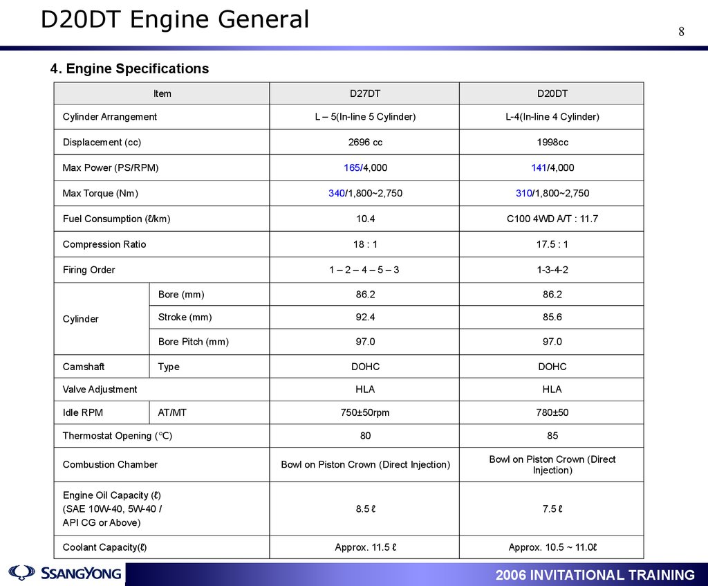
D20DT Engine General8
4. Engine Specifications
Item
D27DT
D20DT
L – 5(In-line 5 Cylinder)
L-4(In-line 4 Cylinder)
2696 cc
1998cc
165/4,000
141/4,000
340/1,800~2,750
310/1,800~2,750
Fuel Consumption (ℓ/km)
10.4
C100 4WD A/T : 11.7
Compression Ratio
18 : 1
17.5 : 1
1–2–4–5–3
1-3-4-2
Bore (mm)
86.2
86.2
Stroke (mm)
92.4
85.6
Bore Pitch (mm)
97.0
97.0
DOHC
DOHC
HLA
HLA
750±50rpm
780±50
80
85
Combustion Chamber
Bowl on Piston Crown (Direct Injection)
Bowl on Piston Crown (Direct
Injection)
Engine Oil Capacity (ℓ)
(SAE 10W-40, 5W-40 /
API CG or Above)
8.5 ℓ
7.5 ℓ
Approx. 11.5 ℓ
Approx. 10.5 ~ 11.0ℓ
Cylinder Arrangement
Displacement (cc)
Max Power (PS/RPM)
Max Torque (Nm)
Firing Order
Cylinder
Camshaft
Type
Valve Adjustment
Idle RPM
AT/MT
Thermostat Opening (℃)
Coolant Capacity(ℓ)
1
2006 INVITATIONAL TRAINING
9.
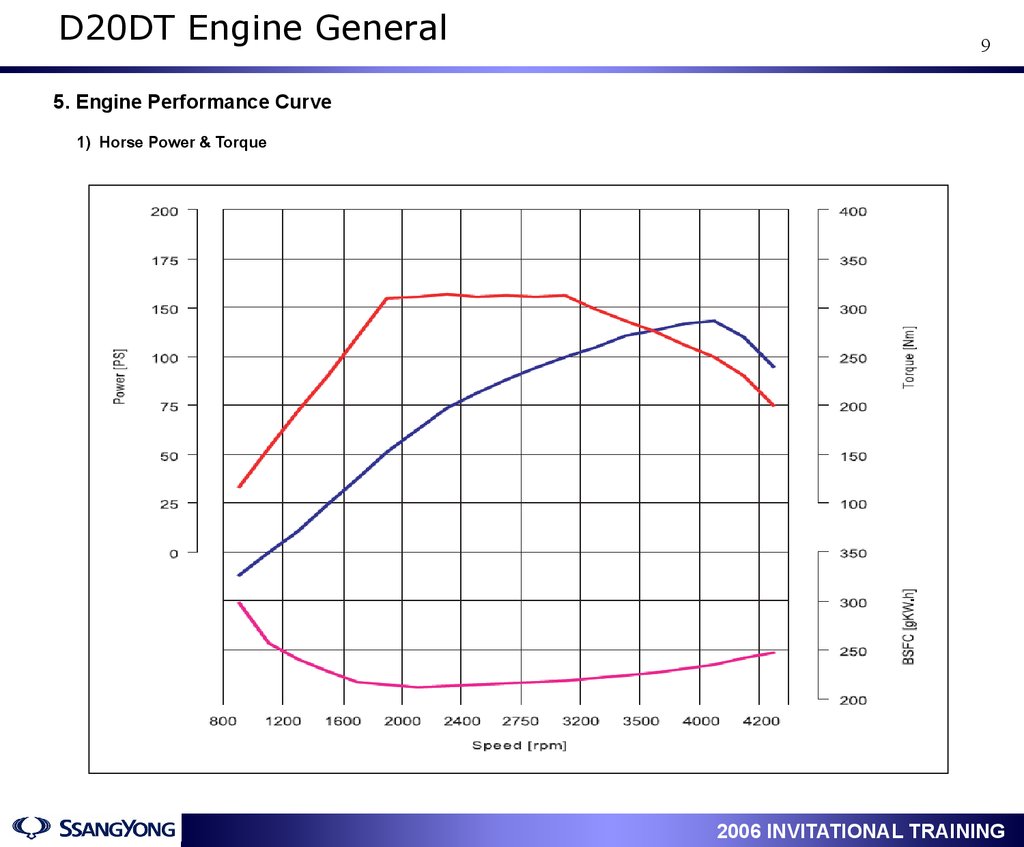
D20DT Engine General9
5. Engine Performance Curve
1) Horse Power & Torque
1
2006 INVITATIONAL TRAINING
10.
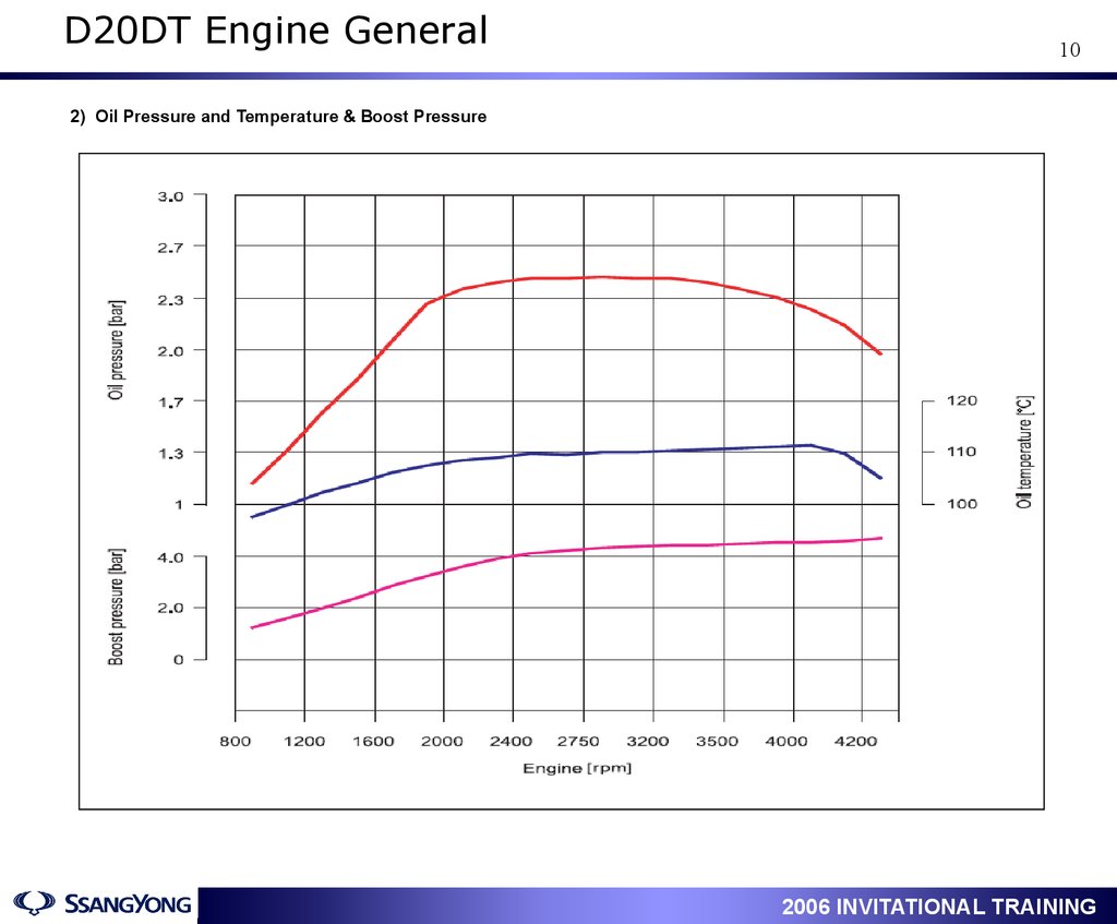
D20DT Engine General10
2) Oil Pressure and Temperature & Boost Pressure
1
2006 INVITATIONAL TRAINING
11.
D20DT Engine General11
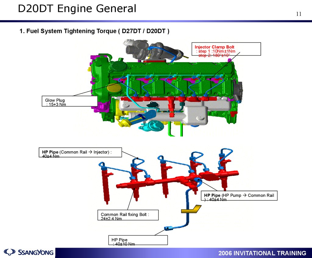
1. Fuel System Tightening Torque ( D27DT / D20DT )
Injector Clamp Bolt
: step 1 :10Nm±1Nm
step 2: 180˚±10˚
Glow Plug
: 15+3 Nm
HP Pipe (Common Rail Injector) :
40±4 Nm
HP Pipe (HP Pump Common Rail
) : 40±4 Nm
Common Rail fixing Bolt :
24±2.4 Nm
HP Pipe
: 40±10 Nm
1
2006 INVITATIONAL TRAINING
12.
D20DT Engine General12
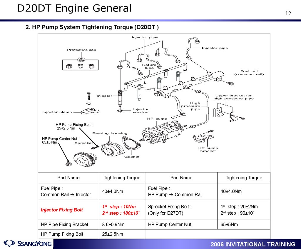
2. HP Pump System Tightening Torque (D20DT )
HP Pump Fixing Bolt :
25+2.5 Nm
HP Pump Center Nut :
65±5 Nm
Part Name
Tightening Torque
Part Name
Tightening Torque
Fuel Pipe :
Common Rail Injector
40±4.0Nm
Fuel Pipe :
HP Pump Common Rail
40±4.0Nm
Injector Fixing Bolt
1st step : 10Nm
2nd step : 180±10˚
Sprocket Fixing Bolt :
(Only for D27DT)
1st step : 20±2Nm
2nd step : 90±10˚
HP Pipe Fixing Bracket
8.6±0.9Nm
HP Pump Center Nut
65±5Nm
HP Pump Fixing Bolt
25±2.5Nm
1
2006 INVITATIONAL TRAINING
13.
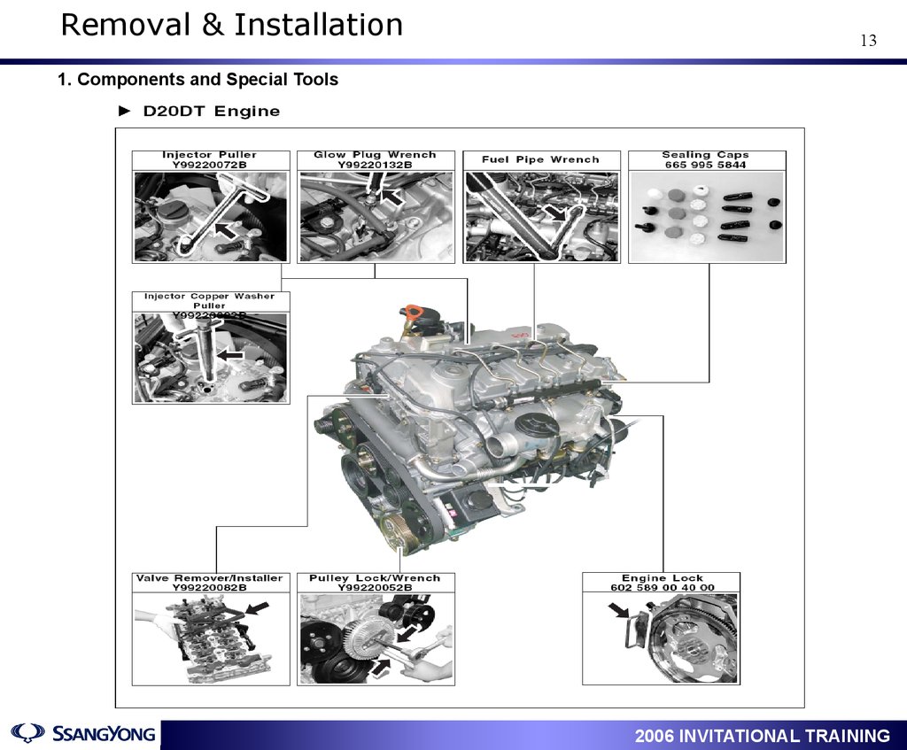
Removal & Installation13
1. Components and Special Tools
1
2006 INVITATIONAL TRAINING
14.
Removal & Installation14
1
2006 INVITATIONAL TRAINING
15.
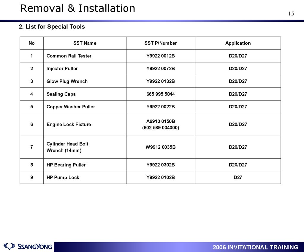
Removal & Installation15
2. List for Special Tools
No
SST Name
SST P/Number
Application
1
Common Rail Tester
Y9922 0012B
D20/D27
2
Injector Puller
Y9922 0072B
D20/D27
3
Glow Plug Wrench
Y9922 0132B
D20/D27
4
Sealing Caps
665 995 5844
D20/D27
5
Copper Washer Puller
Y9922 0022B
D20/D27
6
Engine Lock Fixture
A9910 0150B
(602 589 004000)
D20/D27
7
Cylinder Head Bolt
Wrench (14mm)
W9912 0035B
D20/D27
8
HP Bearing Puller
Y9922 0302B
D20/D27
9
HP Pump Lock
Y9922 0102B
D27
1
2006 INVITATIONAL TRAINING
16.
Removal & Installation16
3. D20DT HP Pump Removal & Installation
1) Removal
Preceding Works:
▪ Disconnect the negative battery cable.
▪ Apply the parking brake and place the chocks under the tires.
(transmission “N” position)
1. Turn the auto tensioner counterclockwise
and remove the fan belt.
2. Remove the engine belt pulleys.
1) Cooling fan pulley
③
2) Coolant pump pulley
②
①
3. Unscrew lower bolt (13 mm) and upper bolt
(24 mm) and remove the auto tensioner.
• To prevent oil leaks, place the removed
auto tensioner in upright position.
• Pump the auto tensioner several times
before installing it.
1
2006 INVITATIONAL TRAINING
17.
Removal & Installation17
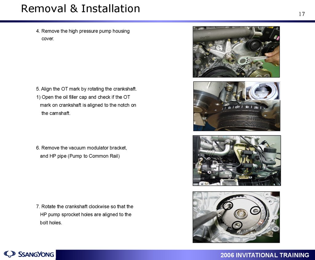
4. Remove the high pressure pump housing
cover.
5. Align the OT mark by rotating the crankshaft.
1) Open the oil filler cap and check if the OT
mark on crankshaft is aligned to the notch on
the camshaft.
6. Remove the vacuum modulator bracket,
and HP pipe (Pump to Common Rail)
7. Rotate the crankshaft clockwise so that the
HP pump sprocket holes are aligned to the
bolt holes.
1
2006 INVITATIONAL TRAINING
18.
Removal & Installation18
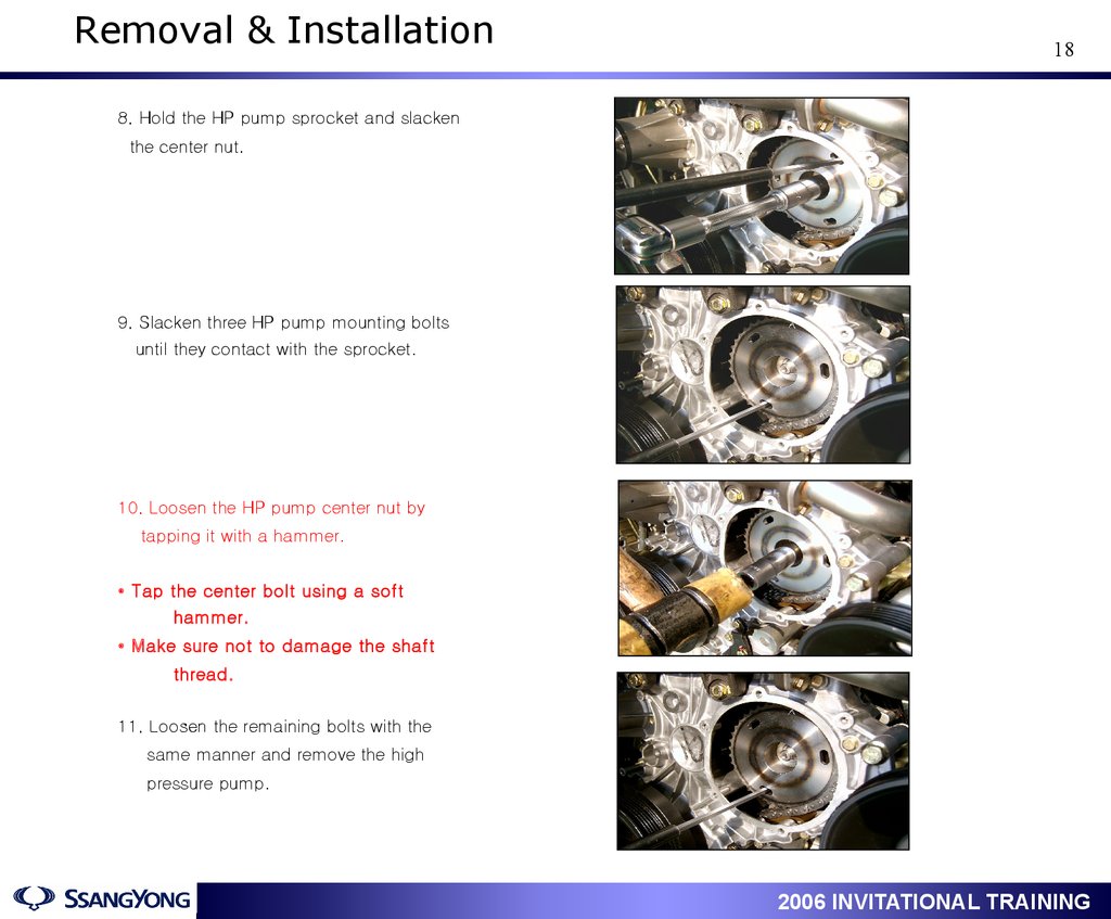
8. Hold the HP pump sprocket and slacken
the center nut.
9. Slacken three HP pump mounting bolts
until they contact with the sprocket.
10. Loosen the HP pump center nut by
tapping it with a hammer.
• Tap the center bolt using a soft
hammer.
• Make sure not to damage the shaft
thread.
11. Loosen the remaining bolts with the
same manner and remove the high
pressure pump.
1
2006 INVITATIONAL TRAINING
19.
Removal & Installation19
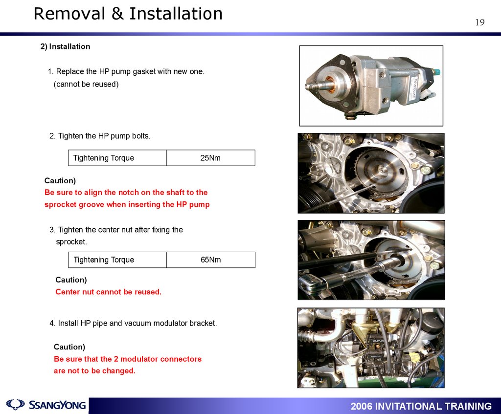
2) Installation
1. Replace the HP pump gasket with new one.
(cannot be reused)
2. Tighten the HP pump bolts.
Tightening Torque
25Nm
Caution)
Be sure to align the notch on the shaft to the
sprocket groove when inserting the HP pump
3. Tighten the center nut after fixing the
sprocket.
Tightening Torque
65Nm
Caution)
Center nut cannot be reused.
4. Install HP pipe and vacuum modulator bracket.
Caution)
Be sure that the 2 modulator connectors
are not to be changed.
1
2006 INVITATIONAL TRAINING
20.
Removal & Installation20
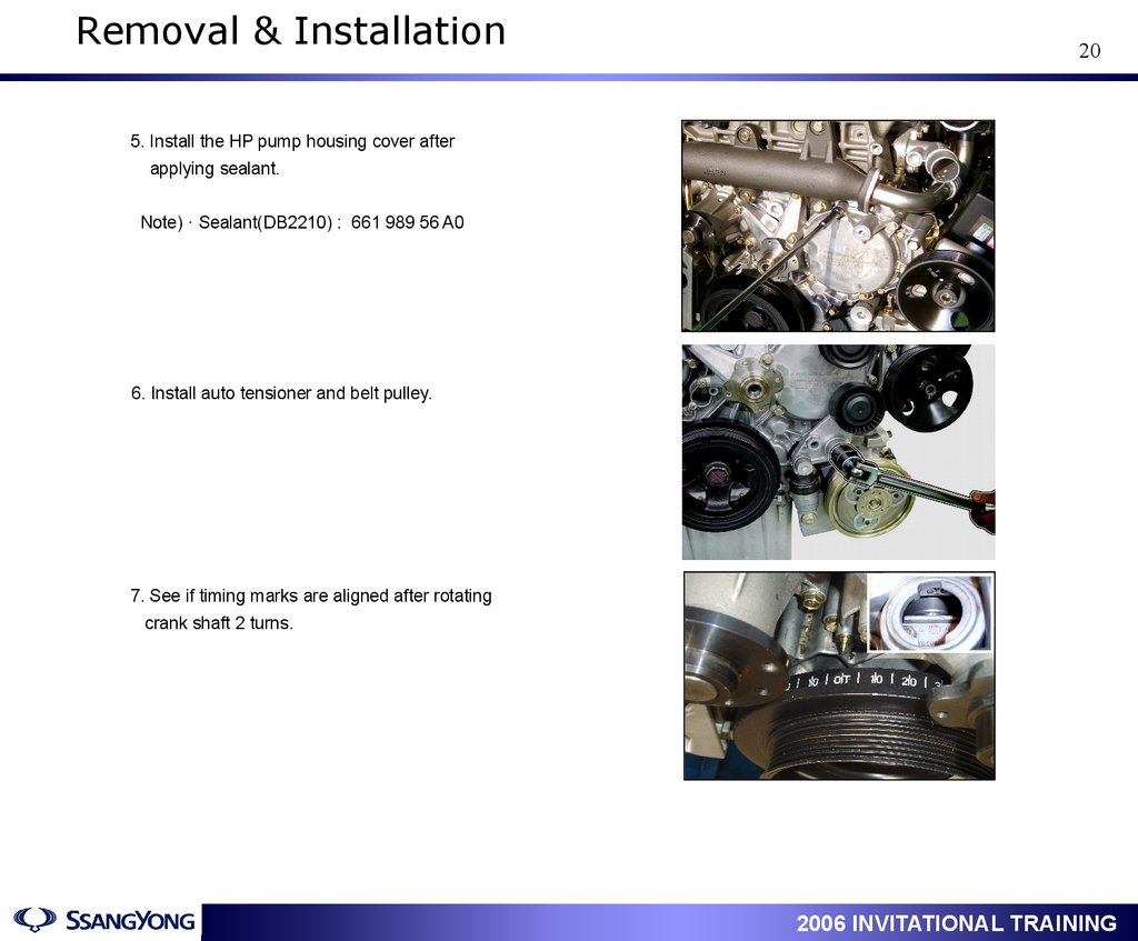
5. Install the HP pump housing cover after
applying sealant.
Note) · Sealant(DB2210) : 661 989 56 A0
6. Install auto tensioner and belt pulley.
7. See if timing marks are aligned after rotating
crank shaft 2 turns.
1
2006 INVITATIONAL TRAINING
21.
Removal & Installation21
3. D20DT HP Pump Timing Setting
The teeth number of
Ex. Cam sprocket
40EA
The teeth number of
Ex. cam sprocket
40EA
Chain Tensioner
Tightening Toque
60Nm
The number of teeth
of HP Pump sprocket
40EA
The number of teeth of
crank sprocket 20EA
The number of teeth of
oil pump sprocket
26EA
① When installing/removing of chain or sprocket, must align the timing mark “▶”
and copper mark on crank, HP pump and IN/EX manifold sprocket.
② It is necessary to align the HP pump sprocket.
③ Major difference
D27DT
D20DT
Teeth number of HP pump sprocket
32 teeth
40 teeth
Number of Chain link
144 links
148 links
Crank rotations to coincide chain & sprocket
timing marks
144 turns
74 turns
1
2006 INVITATIONAL TRAINING
22.
Removal & Installation22
4. Glow plug distinction
When replacing one or more plugs, must use the same type by distinguishing the color of insulator.
▶ Vendor : BERU φ 4
▶ Application : D20DT & D27DT
Green
▶ Resistance : 680±110mΩ( at 20℃)
▶ Vendor : NGK φ 3.5
▶ Application : D20DT & D27DT
Yellow
▶ Resistance : 140±30mΩ( at 20℃)
▶ Vendor : NGK AQGS φ 3.5
▶ Application : D27DT Euro-IV
Red
▶ Resistance : 140±30mΩ( at 20℃)
Diameter of Tip
- BERU : 4.0mm
- NGK : 3.5mm
Color of Insulator
- Green : BERU
- Yellow : NGK
1
2006 INVITATIONAL TRAINING
23.
Removal & Installation23
5. D20DT/D27DT Parts major difference
D27DT
D20DT(Actyon/Kyron)
D20DT
D27DT
New Rexton
Rodius(Stavic)
665 180 05 01
665 180 06 01
D27DT(RD)
Photo
Oil Pump
P/N
Feature
664 180 03 01
Higher basket than
others
Basket hole 7
o’clock direction
Basket hole 9
o’clock direction
D20DT:148 links
Photo
D27DT: 144 links
Timing Chain
P/N
Feature
664 997 01 94
665 997 00 94
D20DT is 4 links longer than D27DT
40 teeth
32 teeth
Photo
HP pump sprocket
P/N
Feature
664 075 02 29
665 075 01 29
D20DT is bigger than D27DT
D20DT sprocket incorporates bearing shaft.
D27DT sprocket separates bearing shaft.
1
2006 INVITATIONAL TRAINING
24.
Removal & Installation24
D27DT
D20DT
New Rexton / Rodius
Photo
Chain Tensioner
P/N
Feature
664 050 00 11
665 050 00 11
D20DT is blue painting cap on the top
Spring constant for D20DT is greater than D27DT
Photo
D20DT
D27DT
Injector
P/N
Feature
664 017 00 21
665 017 01 21
Distinguished by color : - D20DT : Green / D27DT : Yellow
No of injector hole : - D20DT : 6 holes / D27DT : 5 holes
#1
#2
#3
#4
#1
D20DT
Photo
#2
#3
#4
#5
D27DT
Fuel Pipe ( Common Rail Injector )
P/N
Feature
664 070 00 33(No.1)
664 070 01 33(No.2)
664 070 03 33(No.3)
664 070 04 33(No.4)
665 070 06 33(1&3)
665 070 07 33(2&4)
665 070 08 33(5)
Different color
- D20DT : Silver / D27DT : Bronze
1
2006 INVITATIONAL TRAINING
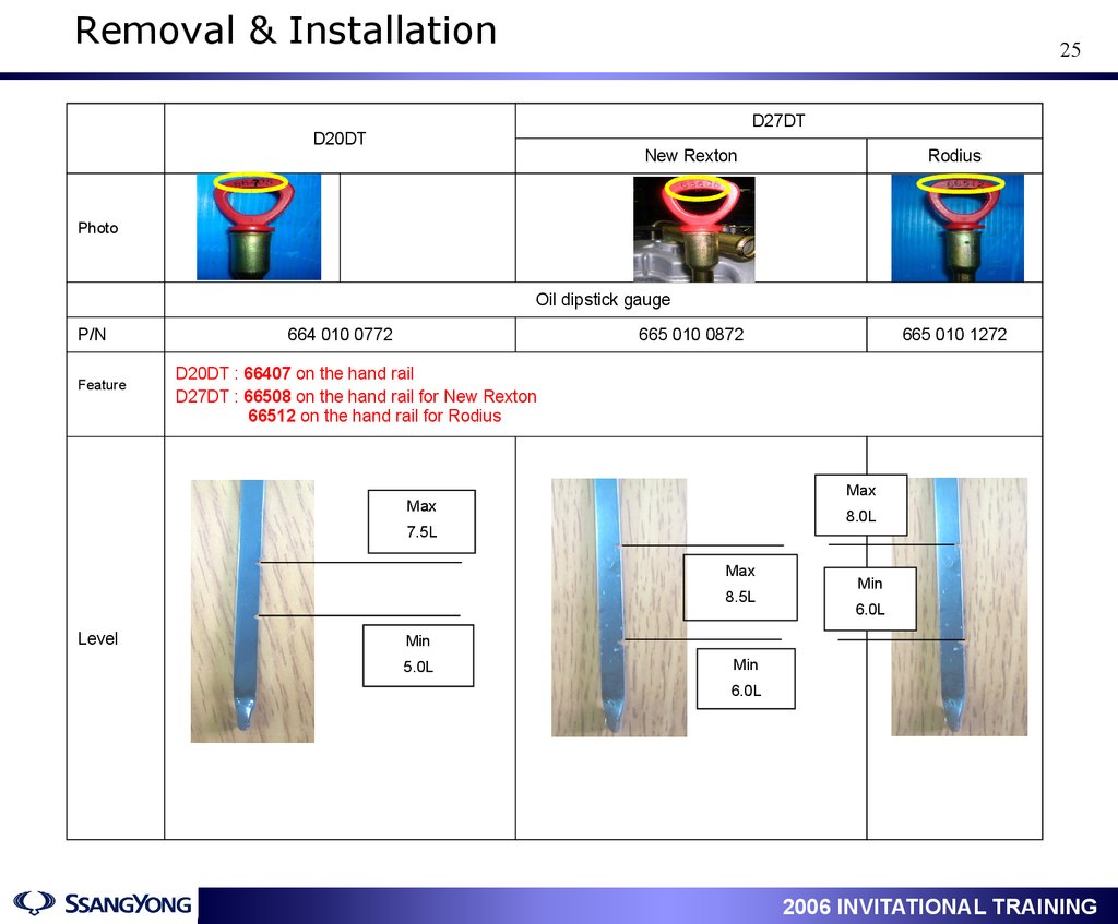
25.
Removal & Installation25
D27DT
D20DT
New Rexton
Rodius
7
Photo
Oil dipstick gauge
P/N
Feature
664 010 0772
665 010 0872
D20DT : 66407 on the hand rail
D27DT : 66508 on the hand rail for New Rexton
66512 on the hand rail for Rodius
Max
Max
8.0L
7.5L
Max
8.5L
Level
665 010 1272
Min
6.0L
Min
Min
5.0L
6.0L
1
2006 INVITATIONAL TRAINING
26.
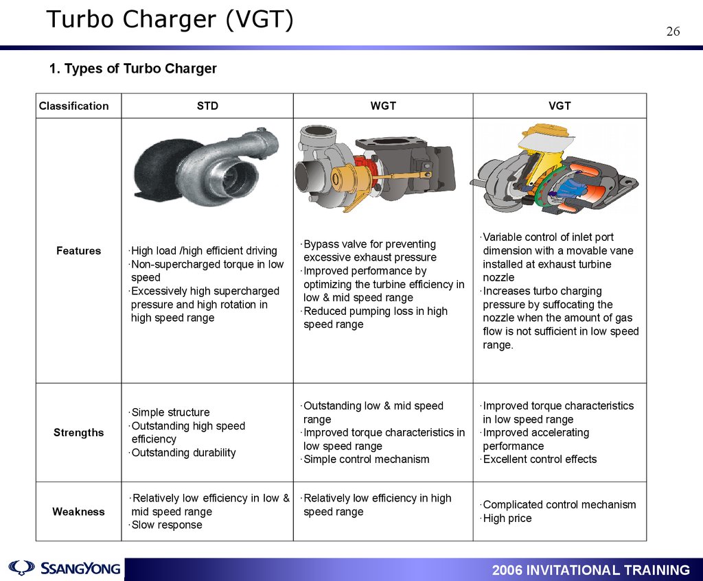
Turbo Charger (VGT)26
1. Types of Turbo Charger
Classification
STD
WGT
·High load /high efficient driving
·Non-supercharged torque in low
speed
·Excessively high supercharged
pressure and high rotation in
high speed range
·Bypass valve for preventing
excessive exhaust pressure
·Improved performance by
optimizing the turbine efficiency in
low & mid speed range
·Reduced pumping loss in high
speed range
Strengths
·Simple structure
·Outstanding high speed
efficiency
·Outstanding durability
·Outstanding low & mid speed
range
·Improved torque characteristics in
low speed range
·Simple control mechanism
Weakness
·Relatively low efficiency in low & ·Relatively low efficiency in high
mid speed range
speed range
·Slow response
Features
1
VGT
·Variable control of inlet port
dimension with a movable vane
installed at exhaust turbine
nozzle
·Increases turbo charging
pressure by suffocating the
nozzle when the amount of gas
flow is not sufficient in low speed
range.
·Improved torque characteristics
in low speed range
·Improved accelerating
performance
·Excellent control effects
·Complicated control mechanism
·High price
2006 INVITATIONAL TRAINING
27.
Turbo Charger (VGT)27
2. VGT Principle (Variable Geometry Turbocharger)
▷ This is the method to improve the torque in low & mid
VGT Turbo
Power
speed range and to control variably the size of the
exhaust turbine inlet size for lowering the exhaust gas
WGT Turbo
(smoke/PM) and enlarging the maximum output
1000
Engine Speed, RPM
4500
Low RPM
■ Exhaust gas passage becomes narrow
Gas speed increases
Turbine blade runs fast
High RPM
■ Exhaust gas passage becomes wide
Gas amount increases
Turbine blade runs fast
1
2006 INVITATIONAL TRAINING
28.
Turbo Charger (VGT)28
3. VGT Non-Operating Conditions
In case of the following conditions, ECU stops VGT control.
√ Lower than 700RPM
√ Below 0℃
√ EGR related trouble stored in ECU
√ VGT Actuator faulty
√ Boost Pressure Sensor faulty
√ Air Flow Sensor faulty
√ Accelerator Pedal Sensor faulty
4. VGT related Data List of Scan-100
① VGT vacuum modulator operating status
Engine Status
Modulator Duty(%)
Vane Control Actuator
Vane Passage
Low load & low rpm
75%
(Duty Increases)
Pulling
(Vacuum Applies)
Narrow
High load & high rpm
45%
(Duty Decreases)
Return
(Vacuum Releases)
Wide
② VGT vacuum modulator valve duty (%)
This represents that how much the ECU opens and closes the VGT vacuum modulator, Duty value increases to 75%
so that the VGT control actuator pulls the vane and the gas passage becomes narrow when low load/low speed.
When high load/speed, Duty value decreases to 45% so that the VGT control actuator releases and gas passage
becomes wide by the return spring force.
③ Boost Pressure Sensor Value (mbar)
This indicates that the pressure generated in the event of air compression by turbo charging.
- Output value : varies in between 1000 ~ 2,700mbar
1
2006 INVITATIONAL TRAINING
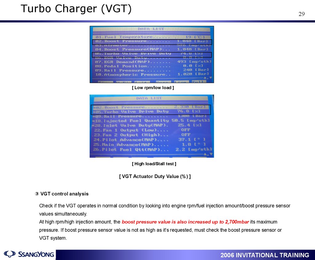
29.
Turbo Charger (VGT)29
[ Low rpm/low load ]
[ High load/Stall test ]
[ VGT Actuator Duty Value (%) ]
③ VGT control analysis
Check if the VGT operates in normal condition by looking into engine rpm/fuel injection amount/boost pressure sensor
values simultaneously.
At high rpm/high injection amount, the boost pressure value is also increased up to 2,700mbar its maximum
pressure. If boost pressure sensor value is not as high as it’s requested, must check the boost pressure sensor or
VGT system.
1
2006 INVITATIONAL TRAINING
30.
Turbo Charger (VGT)30
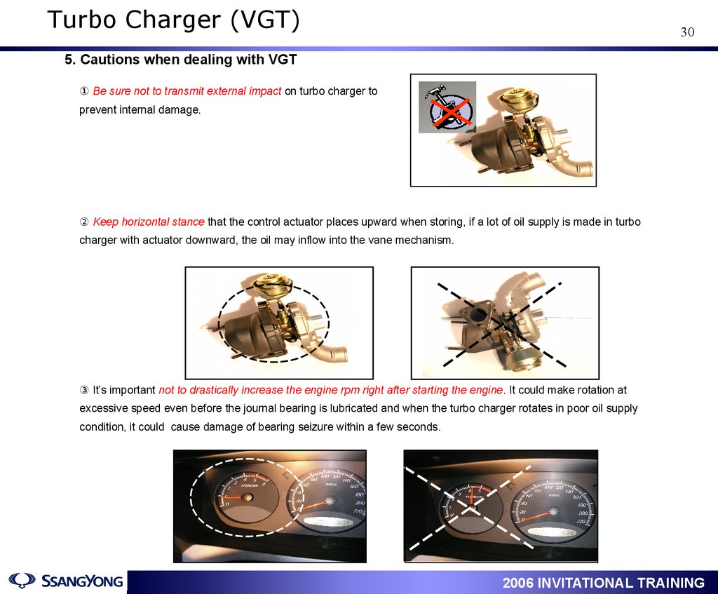
5. Cautions when dealing with VGT
① Be sure not to transmit external impact on turbo charger to
prevent internal damage.
② Keep horizontal stance that the control actuator places upward when storing, if a lot of oil supply is made in turbo
charger with actuator downward, the oil may inflow into the vane mechanism.
③ It’s important not to drastically increase the engine rpm right after starting the engine. It could make rotation at
excessive speed even before the journal bearing is lubricated and when the turbo charger rotates in poor oil supply
condition, it could cause damage of bearing seizure within a few seconds.
1
2006 INVITATIONAL TRAINING
31.
Turbo Charger (VGT)31
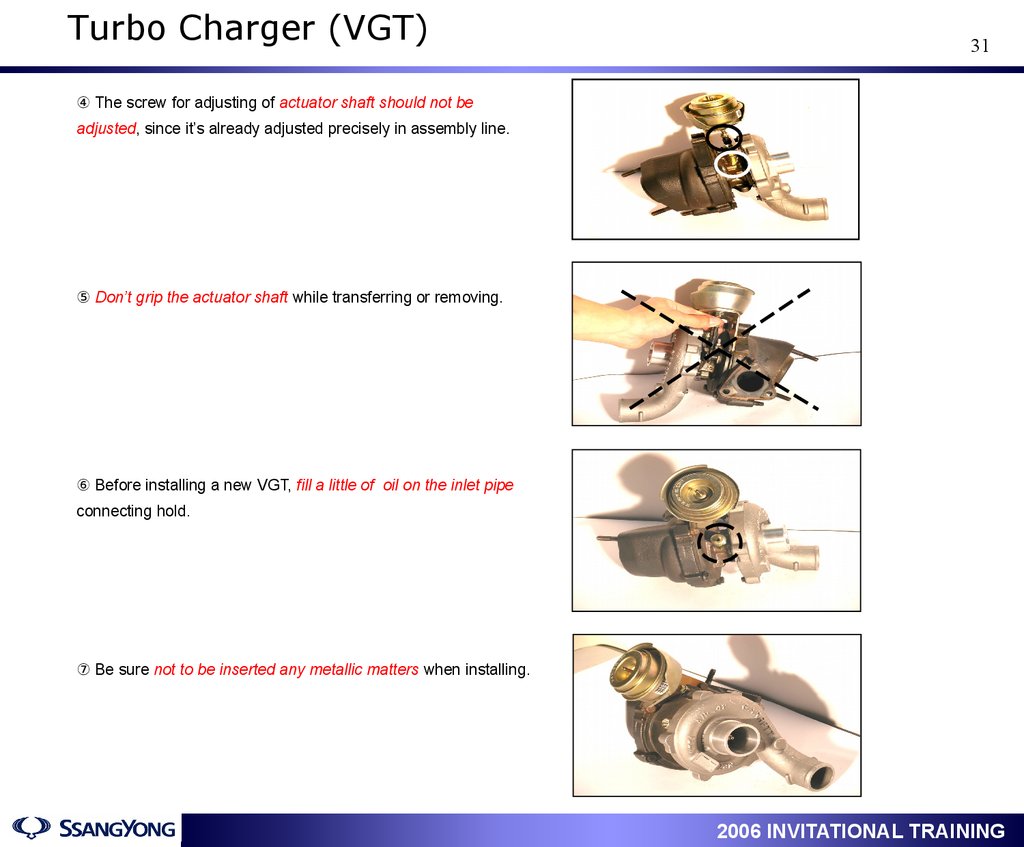
④ The screw for adjusting of actuator shaft should not be
adjusted, since it’s already adjusted precisely in assembly line.
⑤ Don’t grip the actuator shaft while transferring or removing.
⑥ Before installing a new VGT, fill a little of oil on the inlet pipe
connecting hold.
⑦ Be sure not to be inserted any metallic matters when installing.
1
2006 INVITATIONAL TRAINING
32.
Diagnosis32
1. ECU Connector
1
2006 INVITATIONAL TRAINING
33.
Diagnosis33
2. ECU Terminal Description
Pin Number
D27DT
D20DT
1
Engine Ground
Engine Ground
2
Engine Ground
Engine Ground
3
Main Power (B+)
Main Power (B+)
4
Main Power (B+)
Main Power (B+)
5
Main Power (B+)
Main Power (B+)
6
RPS power supply
RPS power supply
7
-
-
8
-
-
9
Engine Main Relay
Engine Main Relay
10
-
-
11
-
-
12
Neutral s/w(only for New Rexton)
13
14
Remarks
-
-
-
Accel Pedal Sensor 2 ground
Accel Pedal Sensor 2 ground
15
-
-
16
-
-
17
Auto Cruise OFF
Auto Cruise OFF
18
Auto Cruise Safety S/W
Auto Cruise Safety S/W
19
A/C Pressure Signal (Hi/Low)
A/C Pressure Signal (Hi/Low)
20
25
-
-
RPS Signal
RPS Signal
1
2006 INVITATIONAL TRAINING
34.
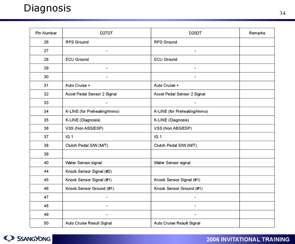
DiagnosisPin Number
26
34
D27DT
RPS Ground
27
28
D20DT
RPS Ground
-
-
ECU Ground
ECU Ground
29
-
-
30
-
-
31
Auto Cruise +
Auto Cruise +
32
Accel Pedal Sensor 2 Signal
Accel Pedal Sensor 2 Signal
33
Remarks
-
-
34
K-LINE (for Preheating/Immo)
K-LINE (for Preheating/Immo)
35
K-LINE (Diagnosis)
K-LINE (Diagnosis)
36
VSS (Non ABS/ESP)
VSS (Non ABS/ESP)
37
IG 1
IG 1
38
Clutch Pedal S/W (M/T)
Clutch Pedal S/W (M/T)
40
Water Sensor signal
Water Sensor signal
44
Knock Sensor Signal (#2)
45
Knock Sensor Signal (#1)
Knock Sensor Signal (#1)
46
Knock Sensor Ground (#1)
Knock Sensor Ground (#1)
39
47
-
-
48
-
-
49
-
-
50
Auto Cruise Result Signal
Auto Cruise Result Signal
1
2006 INVITATIONAL TRAINING
35.
DiagnosisPin Number
35
D27DT
D20DT
53
Accel Pedal Sensor 1 Ground
Accel Pedal Sensor 1 Ground
54
CAN - HI
CAN - HI
55
-
-
56
-
-
57
Accel Pedal Sensor 2 Power
Accel Pedal Sensor 2 Power
58
Brake Lamp S/W
Brake Lamp S/W
59
-
-
60
-
-
61
PTC #1 Relay
PTC #1 Relay
62
PTC #2 Relay
PTC #2 Relay
63
Knock Sensor 2 Ground
64
HFM Sensor (Ambient signal)
65
HFM Sensor (Ambient signal)
-
-
66
ECU Ground
ECU Ground
67
Auto Cruise -
Auto Cruise -
68
-
-
71
Accel Pedal Sensor 1 signal
Accel Pedal Sensor 1 signal
72
Accel Pedal Sensor 1 power supply
Accel Pedal Sensor 1 power supply
73
CAN -LO
CAN -LO
74
-
-
75
-
-
1
2006 INVITATIONAL TRAINING
36.
DiagnosisPin Number
36
D27DT
D20DT
76
A/Con Middle Pressure S/W
A/Con Middle Pressure S/W
77
Brake S/W
Brake S/W
78
79
-
-
A/Con Compressor Relay
A/Con Compressor Relay
80
-
-
81
-
-
82
Crank Position Sensor Ground
Crank Position Sensor Ground
83
HFM Sensor Signal
HFM Sensor Signal
84
HFM Sensor Ground
HFM Sensor Ground
85
-
-
86
HFM Sensor Power Supply
HFM Sensor Power Supply
87
IMV
IMV
88
ECU Ground
ECU Ground
89
-
-
90
Crank Position Sensor Signal
Crank Position Sensor Signal
95
WGT Actuator Modulator
VGT Actuator Modulator
96
EGR Vacuum Modulator
EGR Vacuum Modulator
97
-
-
98
-
-
99
Boost Pressure Signal
Boost Pressure Signal
100
Boost Pressure Sensor Ground
Boost Pressure Sensor Ground
1
2006 INVITATIONAL TRAINING
37.
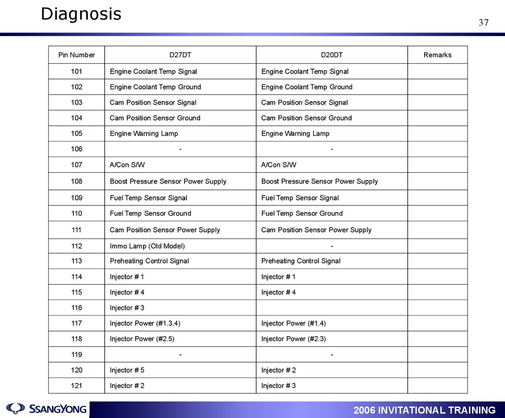
DiagnosisPin Number
37
D27DT
D20DT
101
Engine Coolant Temp Signal
Engine Coolant Temp Signal
102
Engine Coolant Temp Ground
Engine Coolant Temp Ground
103
Cam Position Sensor Signal
Cam Position Sensor Signal
104
Cam Position Sensor Ground
Cam Position Sensor Ground
105
Engine Warning Lamp
Engine Warning Lamp
106
-
Remarks
-
107
A/Con S/W
A/Con S/W
108
Boost Pressure Sensor Power Supply
Boost Pressure Sensor Power Supply
109
Fuel Temp Sensor Signal
Fuel Temp Sensor Signal
110
Fuel Temp Sensor Ground
Fuel Temp Sensor Ground
111
Cam Position Sensor Power Supply
Cam Position Sensor Power Supply
112
Immo Lamp (Old Model)
113
Preheating Control Signal
Preheating Control Signal
114
Injector # 1
Injector # 1
115
Injector # 4
Injector # 4
116
Injector # 3
117
Injector Power (#1.3.4)
Injector Power (#1.4)
118
Injector Power (#2.5)
Injector Power (#2.3)
119
-
-
-
120
Injector # 5
Injector # 2
121
Injector # 2
Injector # 3
1
2006 INVITATIONAL TRAINING
38.
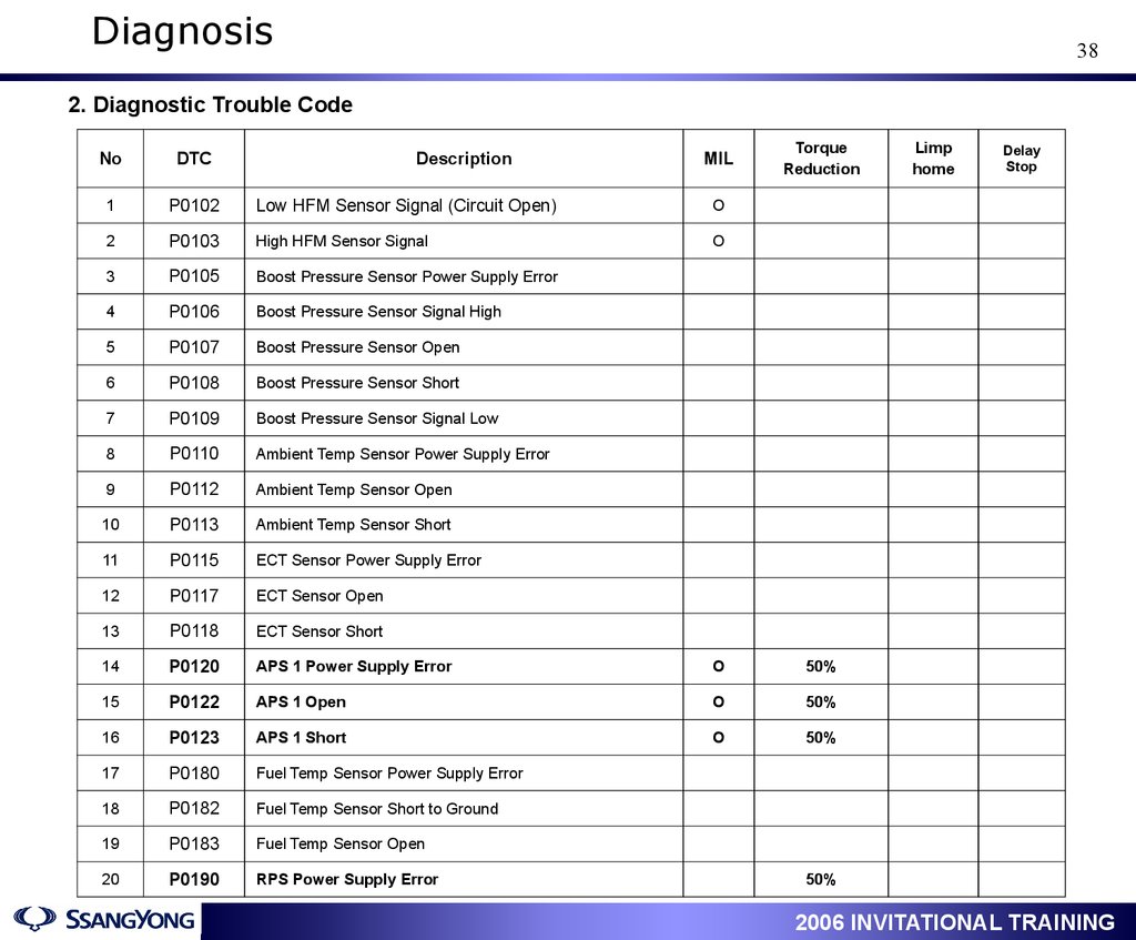
Diagnosis38
2. Diagnostic Trouble Code
Description
MIL
Torque
Reduction
No
DTC
1
P0102
Low HFM Sensor Signal (Circuit Open)
O
2
P0103
High HFM Sensor Signal
O
3
P0105
Boost Pressure Sensor Power Supply Error
4
P0106
Boost Pressure Sensor Signal High
5
P0107
Boost Pressure Sensor Open
6
P0108
Boost Pressure Sensor Short
7
P0109
Boost Pressure Sensor Signal Low
8
P0110
Ambient Temp Sensor Power Supply Error
9
P0112
Ambient Temp Sensor Open
10
P0113
Ambient Temp Sensor Short
11
P0115
ECT Sensor Power Supply Error
12
P0117
ECT Sensor Open
13
P0118
ECT Sensor Short
14
P0120
APS 1 Power Supply Error
O
50%
15
P0122
APS 1 Open
O
50%
16
P0123
APS 1 Short
O
50%
17
P0180
Fuel Temp Sensor Power Supply Error
18
P0182
Fuel Temp Sensor Short to Ground
19
P0183
Fuel Temp Sensor Open
20
P0190
RPS Power Supply Error
Limp
home
Delay
Stop
50%
1
2006 INVITATIONAL TRAINING
39.
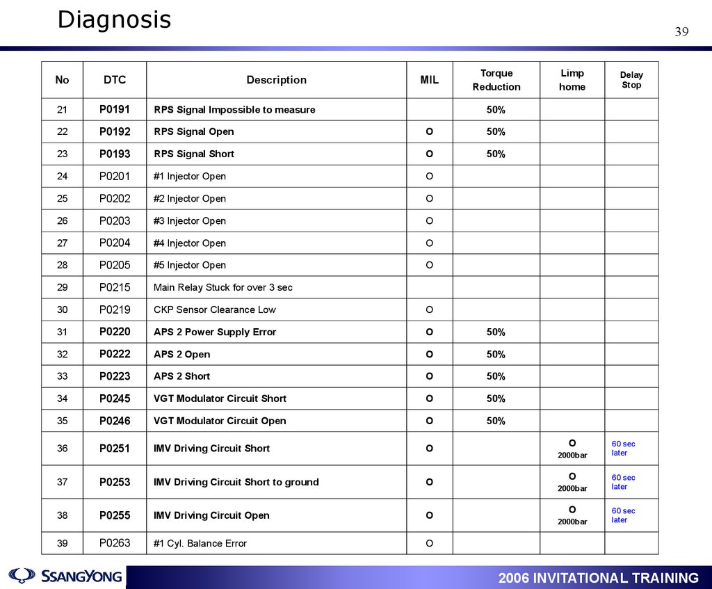
Diagnosis39
Description
MIL
Torque
Reduction
No
DTC
21
P0191
RPS Signal Impossible to measure
22
P0192
RPS Signal Open
O
50%
23
P0193
RPS Signal Short
O
50%
24
P0201
#1 Injector Open
O
25
P0202
#2 Injector Open
O
26
P0203
#3 Injector Open
O
27
P0204
#4 Injector Open
O
28
P0205
#5 Injector Open
O
29
P0215
Main Relay Stuck for over 3 sec
30
P0219
CKP Sensor Clearance Low
O
31
P0220
APS 2 Power Supply Error
O
50%
32
P0222
APS 2 Open
O
50%
33
P0223
APS 2 Short
O
50%
34
P0245
VGT Modulator Circuit Short
O
50%
35
P0246
VGT Modulator Circuit Open
O
50%
36
P0251
IMV Driving Circuit Short
O
37
P0253
IMV Driving Circuit Short to ground
O
38
P0255
IMV Driving Circuit Open
O
39
P0263
#1 Cyl. Balance Error
O
Limp
home
Delay
Stop
50%
1
O
2000bar
O
2000bar
O
2000bar
60 sec
later
60 sec
later
60 sec
later
2006 INVITATIONAL TRAINING
40.
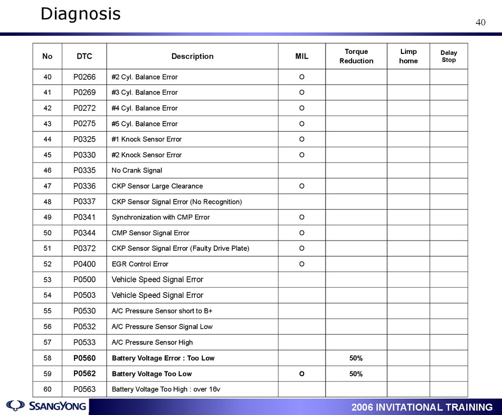
Diagnosis40
No
DTC
Description
MIL
40
P0266
#2 Cyl. Balance Error
O
41
P0269
#3 Cyl. Balance Error
O
42
P0272
#4 Cyl. Balance Error
O
43
P0275
#5 Cyl. Balance Error
O
44
P0325
#1 Knock Sensor Error
O
45
P0330
#2 Knock Sensor Error
O
46
P0335
No Crank Signal
47
P0336
CKP Sensor Large Clearance
48
P0337
CKP Sensor Signal Error (No Recognition)
49
P0341
Synchronization with CMP Error
O
50
P0344
CMP Sensor Signal Error
O
51
P0372
CKP Sensor Signal Error (Faulty Drive Plate)
O
52
P0400
EGR Control Error
O
53
P0500
Vehicle Speed Signal Error
54
P0503
Vehicle Speed Signal Error
55
P0530
A/C Pressure Sensor short to B+
56
P0532
A/C Pressure Sensor Signal Low
57
P0533
A/C Pressure Sensor High
58
P0560
Battery Voltage Error : Too Low
59
P0562
Battery Voltage Too Low
60
P0563
Battery Voltage Too High : over 16v
Torque
Reduction
Limp
home
Delay
Stop
O
50%
O
1
50%
2006 INVITATIONAL TRAINING
41.
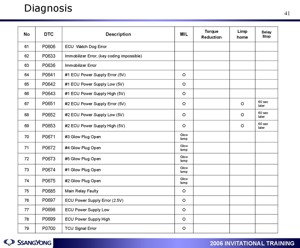
Diagnosis41
Description
MIL
Torque
Reduction
Limp
home
Delay
Stop
No
DTC
61
P0606
ECU Watch Dog Error
62
P0633
Immobilizer Error, (key coding impossible)
63
P0636
Immobilizer Error
64
P0641
#1 ECU Power Supply Error (5V)
O
65
P0642
#1 ECU Power Supply Low (5V)
O
66
P0643
#1 ECU Power Supply High (5V)
O
67
P0651
#2 ECU Power Supply Error (5V)
O
O
60 sec
later
68
P0652
#2 ECU Power Supply Low (5V)
O
O
60 sec
later
69
P0653
#2 ECU Power Supply High (5V)
O
O
60 sec
later
70
P0671
#3 Glow Plug Open
Glow
lamp
71
P0672
#4 Glow Plug Open
Glow
lamp
72
P0673
#5 Glow Plug Open
Glow
lamp
73
P0674
#1 Glow Plug Open
Glow
lamp
74
P0675
#2 Glow Plug Open
Glow
lamp
75
P0685
Main Relay Faulty
O
76
P0697
ECU Power Supply Error (2.5V)
O
77
P0698
ECU Power Supply Low
O
78
P0699
ECU Power Supply High
O
79
P0700
TCU Signal Error
O
1
2006 INVITATIONAL TRAINING
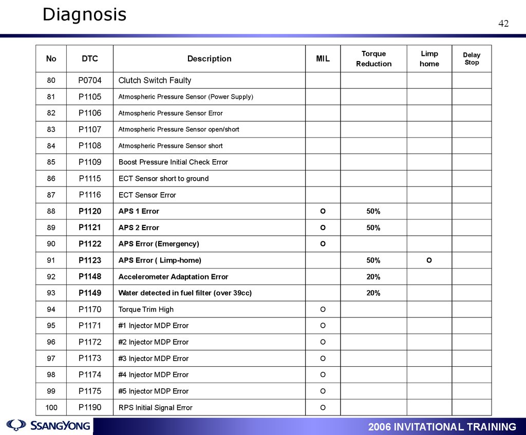
42.
Diagnosis42
MIL
Torque
Reduction
APS 1 Error
O
50%
P1121
APS 2 Error
O
50%
90
P1122
APS Error (Emergency)
O
91
P1123
APS Error ( Limp-home)
50%
92
P1148
Accelerometer Adaptation Error
20%
93
P1149
Water detected in fuel filter (over 39cc)
20%
94
P1170
Torque Trim High
O
95
P1171
#1 Injector MDP Error
O
96
P1172
#2 Injector MDP Error
O
97
P1173
#3 Injector MDP Error
O
98
P1174
#4 Injector MDP Error
O
99
P1175
#5 Injector MDP Error
O
100
P1190
RPS Initial Signal Error
O
No
DTC
Description
80
P0704
Clutch Switch Faulty
81
P1105
Atmospheric Pressure Sensor (Power Supply)
82
P1106
Atmospheric Pressure Sensor Error
83
P1107
Atmospheric Pressure Sensor open/short
84
P1108
Atmospheric Pressure Sensor short
85
P1109
Boost Pressure Initial Check Error
86
P1115
ECT Sensor short to ground
87
P1116
ECT Sensor Error
88
P1120
89
1
Limp
home
Delay
Stop
O
2006 INVITATIONAL TRAINING
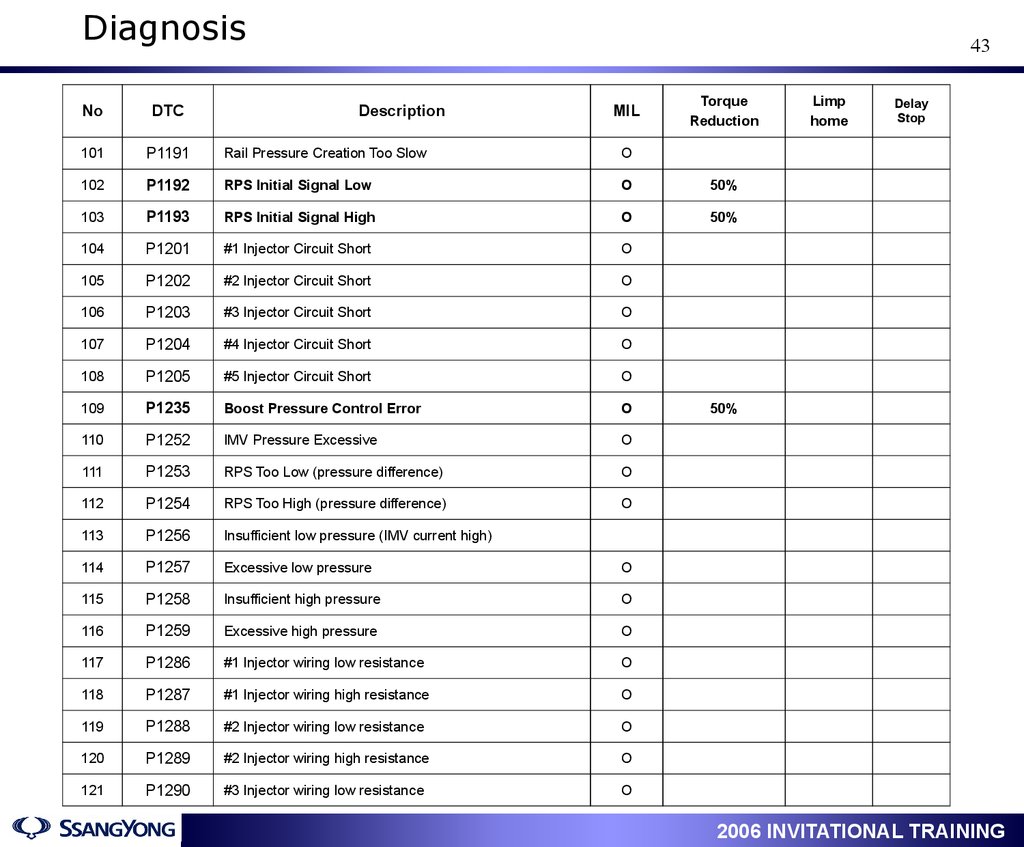
43.
Diagnosis43
Description
MIL
Torque
Reduction
No
DTC
101
P1191
Rail Pressure Creation Too Slow
O
102
P1192
RPS Initial Signal Low
O
50%
103
P1193
RPS Initial Signal High
O
50%
104
P1201
#1 Injector Circuit Short
O
105
P1202
#2 Injector Circuit Short
O
106
P1203
#3 Injector Circuit Short
O
107
P1204
#4 Injector Circuit Short
O
108
P1205
#5 Injector Circuit Short
O
109
P1235
Boost Pressure Control Error
O
110
P1252
IMV Pressure Excessive
O
111
P1253
RPS Too Low (pressure difference)
O
112
P1254
RPS Too High (pressure difference)
O
113
P1256
Insufficient low pressure (IMV current high)
114
P1257
Excessive low pressure
O
115
P1258
Insufficient high pressure
O
116
P1259
Excessive high pressure
O
117
P1286
#1 Injector wiring low resistance
O
118
P1287
#1 Injector wiring high resistance
O
119
P1288
#2 Injector wiring low resistance
O
120
P1289
#2 Injector wiring high resistance
O
121
P1290
#3 Injector wiring low resistance
O
1
Limp
home
Delay
Stop
50%
2006 INVITATIONAL TRAINING
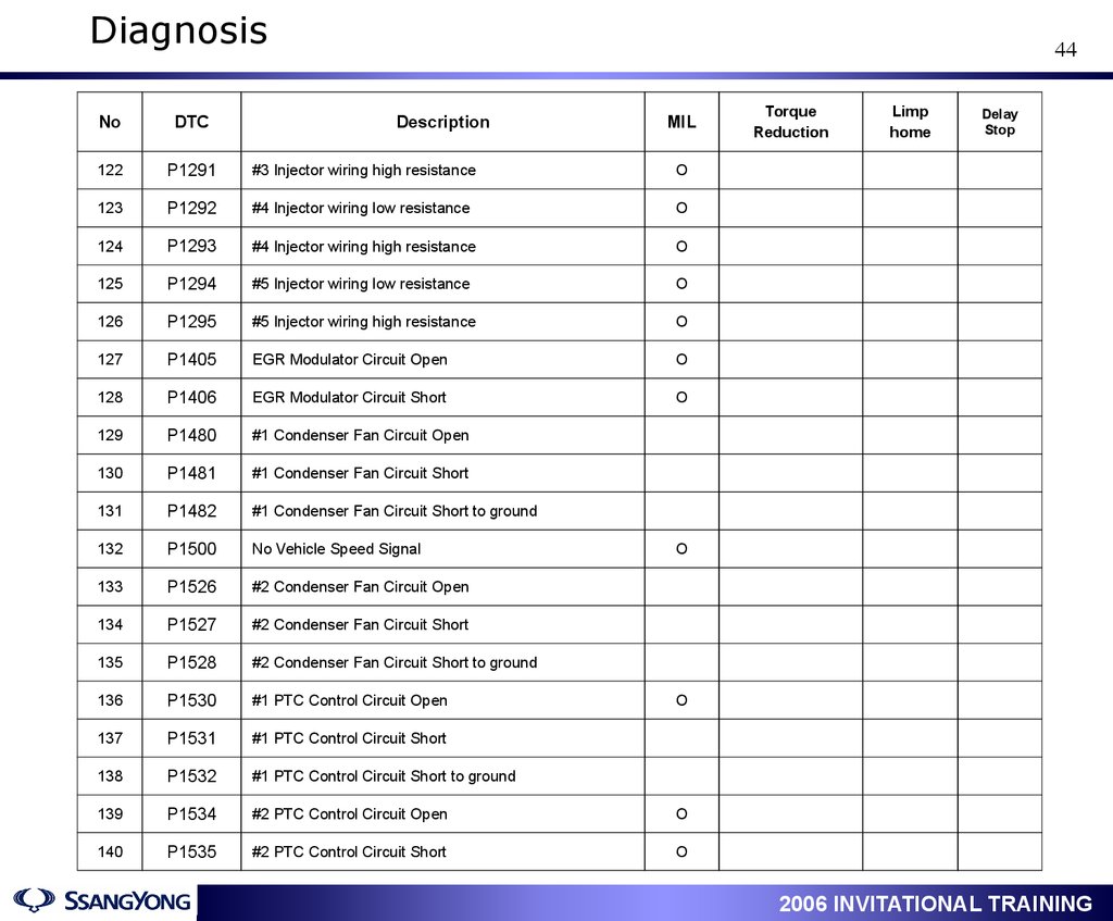
44.
Diagnosis44
No
DTC
Description
MIL
122
P1291
#3 Injector wiring high resistance
O
123
P1292
#4 Injector wiring low resistance
O
124
P1293
#4 Injector wiring high resistance
O
125
P1294
#5 Injector wiring low resistance
O
126
P1295
#5 Injector wiring high resistance
O
127
P1405
EGR Modulator Circuit Open
O
128
P1406
EGR Modulator Circuit Short
O
129
P1480
#1 Condenser Fan Circuit Open
130
P1481
#1 Condenser Fan Circuit Short
131
P1482
#1 Condenser Fan Circuit Short to ground
132
P1500
No Vehicle Speed Signal
133
P1526
#2 Condenser Fan Circuit Open
134
P1527
#2 Condenser Fan Circuit Short
135
P1528
#2 Condenser Fan Circuit Short to ground
136
P1530
#1 PTC Control Circuit Open
137
P1531
#1 PTC Control Circuit Short
138
P1532
#1 PTC Control Circuit Short to ground
139
P1534
#2 PTC Control Circuit Open
O
140
P1535
#2 PTC Control Circuit Short
O
Torque
Reduction
Limp
home
Delay
Stop
O
O
1
2006 INVITATIONAL TRAINING
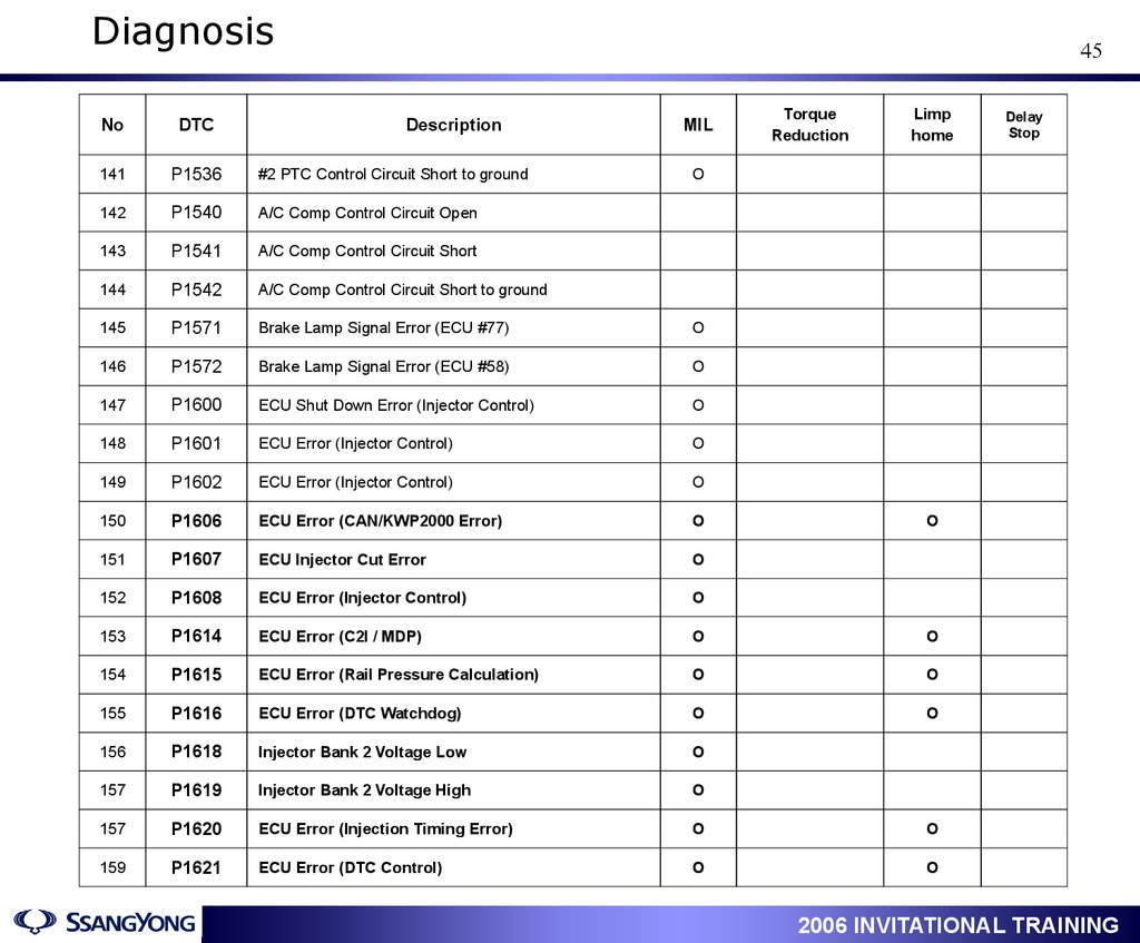
45.
Diagnosis45
Description
MIL
Torque
Reduction
Limp
home
No
DTC
141
P1536
#2 PTC Control Circuit Short to ground
142
P1540
A/C Comp Control Circuit Open
143
P1541
A/C Comp Control Circuit Short
144
P1542
A/C Comp Control Circuit Short to ground
145
P1571
Brake Lamp Signal Error (ECU #77)
O
146
P1572
Brake Lamp Signal Error (ECU #58)
O
147
P1600
ECU Shut Down Error (Injector Control)
O
148
P1601
ECU Error (Injector Control)
O
149
P1602
ECU Error (Injector Control)
O
150
P1606
ECU Error (CAN/KWP2000 Error)
O
151
P1607
ECU Injector Cut Error
O
152
P1608
ECU Error (Injector Control)
O
153
P1614
ECU Error (C2I / MDP)
O
O
154
P1615
ECU Error (Rail Pressure Calculation)
O
O
155
P1616
ECU Error (DTC Watchdog)
O
O
156
P1618
Injector Bank 2 Voltage Low
O
157
P1619
Injector Bank 2 Voltage High
O
157
P1620
ECU Error (Injection Timing Error)
O
O
159
P1621
ECU Error (DTC Control)
O
O
Delay
Stop
O
1
O
2006 INVITATIONAL TRAINING
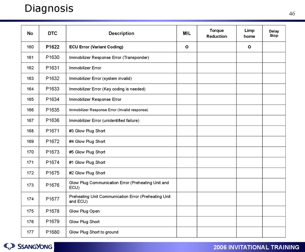
46.
Diagnosis46
No
DTC
Description
MIL
160
P1622
ECU Error (Variant Coding)
161
P1630
Immobilizer Response Error (Transponder)
162
P1631
Immobilizer Error
163
P1632
Immobilizer Error (system invalid)
164
P1633
Immobilizer Error (Key coding is needed)
165
P1634
Immobilizer Response Error
166
P1635
Immobilizer Response Error (Invalid response)
167
P1636
Immobilizer Error (unidentified failure)
168
P1671
#3 Glow Plug Short
169
P1672
#4 Glow Plug Short
170
P1673
#5 Glow Plug Short
171
P1674
#1 Glow Plug Short
172
P1675
#2 Glow Plug Short
173
P1676
Glow Plug Communication Error (Preheating Unit and
ECU)
174
P1677
Preheating Unit Communication Error (Preheating Unit
and ECU)
175
P1678
Glow Plug Open
176
P1679
Glow Plug Short
177
P1680
Glow Plug Short to ground
O
1
Torque
Reduction
Limp
home
Delay
Stop
O
2006 INVITATIONAL TRAINING
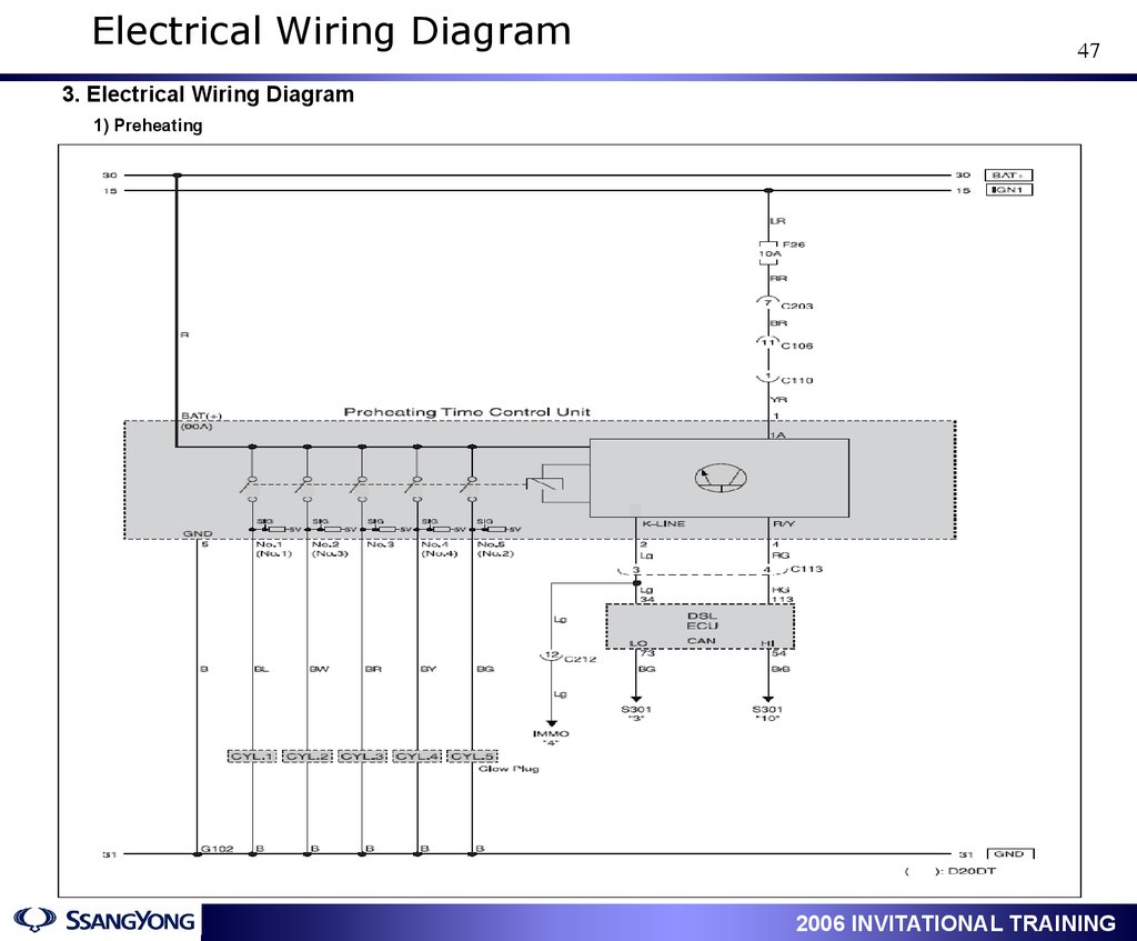
47.
Electrical Wiring Diagram47
3. Electrical Wiring Diagram
1) Preheating
1
2006 INVITATIONAL TRAINING
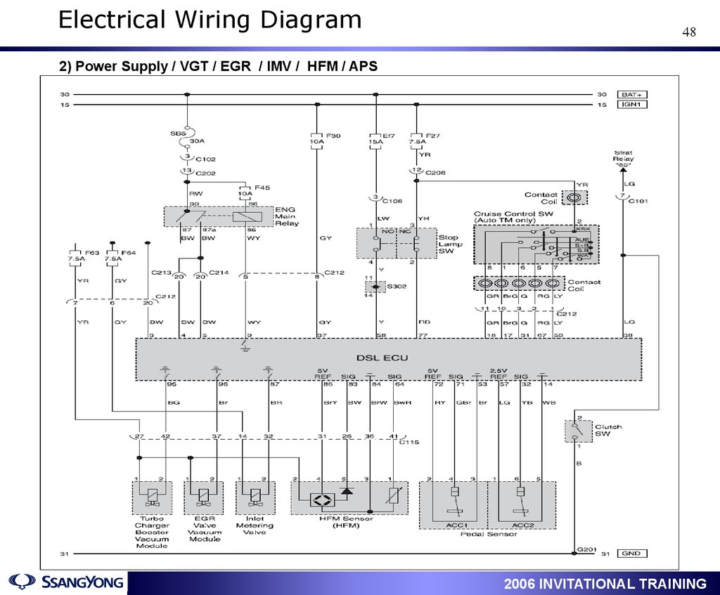
48.
Electrical Wiring Diagram48
2) Power Supply / VGT / EGR / IMV / HFM / APS
1
2006 INVITATIONAL TRAINING
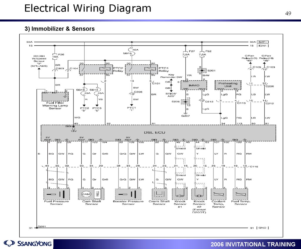
49.
Electrical Wiring Diagram49
3) Immobilizer & Sensors
1
2006 INVITATIONAL TRAINING
50.
Electrical Wiring Diagram50
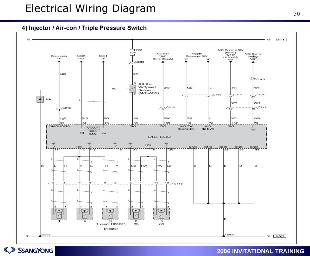
4) Injector / Air-con / Triple Pressure Switch
1
2006 INVITATIONAL TRAINING
51.
Data List Analysis51
레일 압력 현재값과 목표값 (MAP) 을 비교하여 현재값이 낮을경우
연료계통의 기계적 혹은 전기적 문제 ,
현재값과 목표값이 동일하나 , 목표값이 정상차량대비 낮은경우 ,
이는 ECU 연산에 영향을 주는 입력신호의 문제로 접근
Boost Pressure at Idle
Boost Pressure at Stall Test
1
2006 INVITATIONAL TRAINING
52.
Data List Analysis52
D20DT
D27DT
1
2006 INVITATIONAL TRAINING
53.
Data List Analysis53
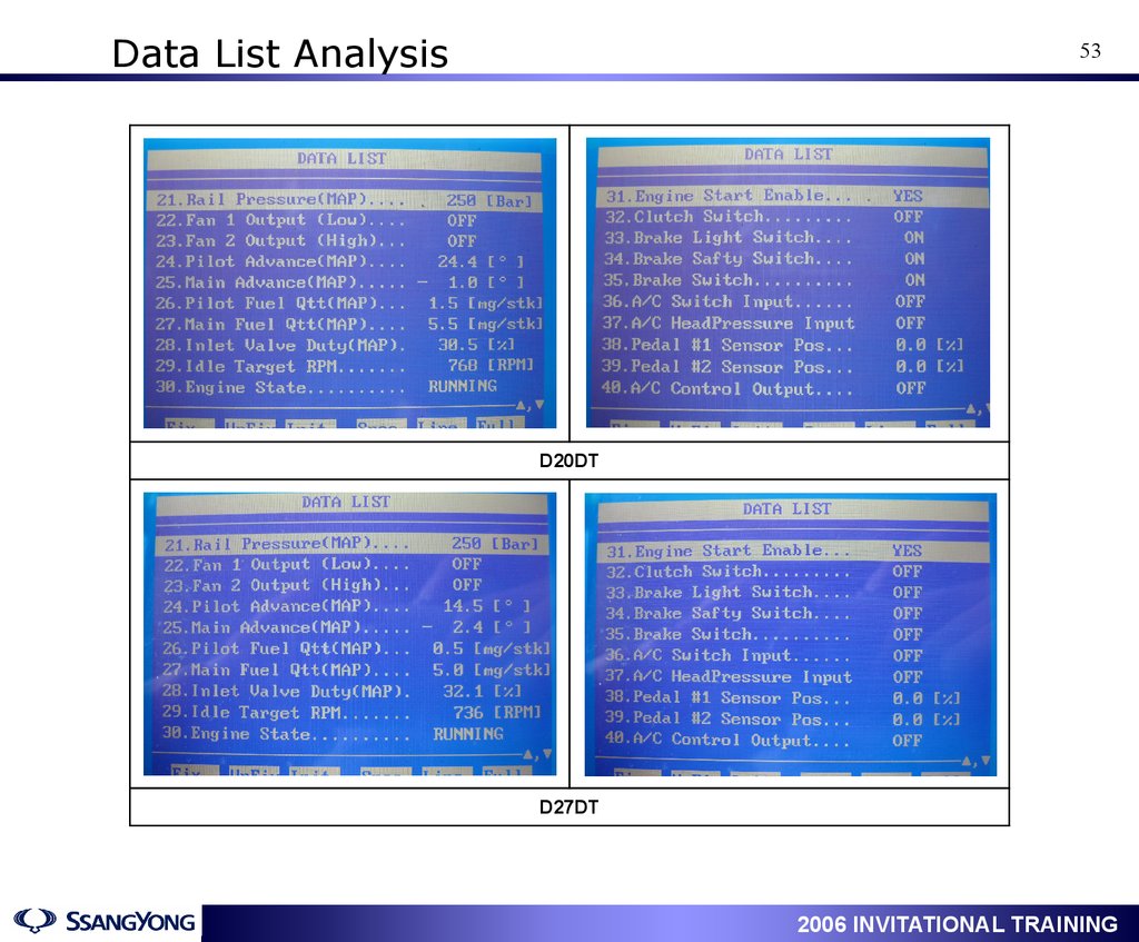
D20DT
D27DT
1
2006 INVITATIONAL TRAINING
54.
Data List Analysis54
D20DT
D27DT
1
2006 INVITATIONAL TRAINING
55.
Data List Analysis55
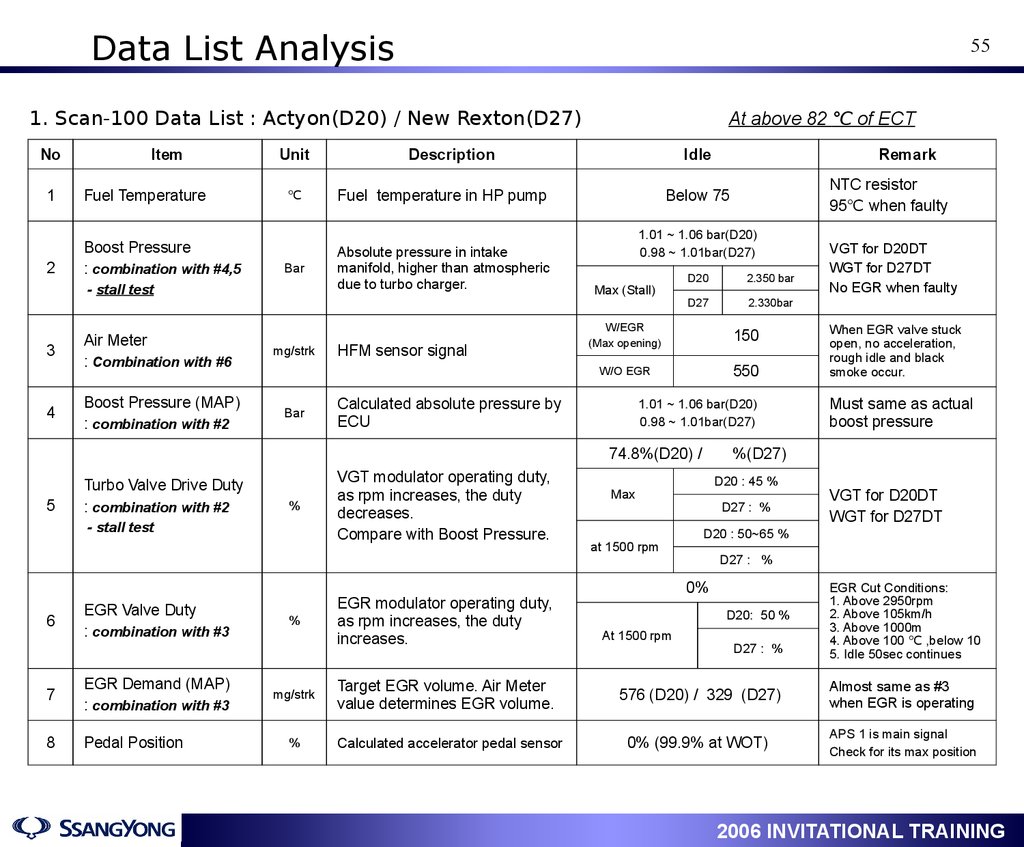
1. Scan-100 Data List : Actyon(D20) / New Rexton(D27)
No
Item
1
Fuel Temperature
2
Boost Pressure
: combination with #4,5
Unit
℃
Bar
- stall test
3
4
Air Meter
: Combination with #6
Boost Pressure (MAP)
: combination with #2
mg/strk
Bar
At above 82 ℃ of ECT
Description
Idle
Fuel temperature in HP pump
Absolute pressure in intake
manifold, higher than atmospheric
due to turbo charger.
HFM sensor signal
1.01 ~ 1.06 bar(D20)
0.98 ~ 1.01bar(D27)
Max (Stall)
D20
2.350 bar
D27
2.330bar
W/EGR
(Max opening)
150
W/O EGR
550
Calculated absolute pressure by
ECU
5
%
- stall test
6
EGR Valve Duty
: combination with #3
7
EGR Demand (MAP)
: combination with #3
8
Pedal Position
%
mg/strk
%
VGT modulator operating duty,
as rpm increases, the duty
decreases.
Compare with Boost Pressure.
EGR modulator operating duty,
as rpm increases, the duty
increases.
NTC resistor
95℃ when faulty
Below 75
1.01 ~ 1.06 bar(D20)
0.98 ~ 1.01bar(D27)
74.8%(D20) /
Turbo Valve Drive Duty
: combination with #2
Remark
D20 : 45 %
D27 : %
Must same as actual
boost pressure
VGT for D20DT
WGT for D27DT
D20 : 50~65 %
D27 : %
0%
D20: 50 %
At 1500 rpm
When EGR valve stuck
open, no acceleration,
rough idle and black
smoke occur.
%(D27)
Max
at 1500 rpm
VGT for D20DT
WGT for D27DT
No EGR when faulty
D27 : %
EGR Cut Conditions:
1. Above 2950rpm
2. Above 105km/h
3. Above 1000m
4. Above 100 ℃ ,below 10
5. Idle 50sec continues
Target EGR volume. Air Meter
value determines EGR volume.
576 (D20) / 329 (D27)
Almost same as #3
when EGR is operating
Calculated accelerator pedal sensor
0% (99.9% at WOT)
APS 1 is main signal
Check for its max position
1
2006 INVITATIONAL TRAINING
56.
Data List AnalysisNo
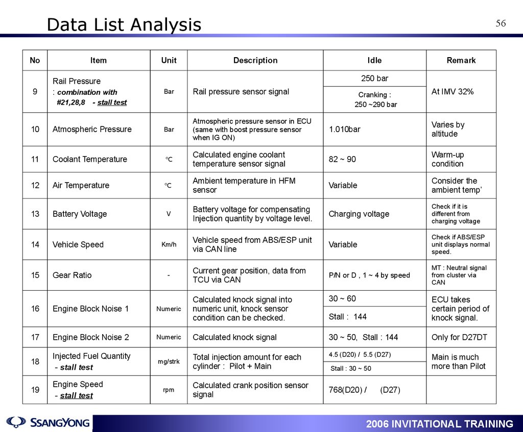
9
Item
Rail Pressure
: combination with
#21,28,8
Unit
56
Description
Idle
Remark
250 bar
Bar
Rail pressure sensor signal
- stall test
Cranking :
250 ~290 bar
At IMV 32%
10
Atmospheric Pressure
Bar
Atmospheric pressure sensor in ECU
(same with boost pressure sensor
when IG ON)
1.010bar
Varies by
altitude
11
Coolant Temperature
℃
Calculated engine coolant
temperature sensor signal
82 ~ 90
Warm-up
condition
12
Air Temperature
℃
Ambient temperature in HFM
sensor
Variable
Consider the
ambient temp’
13
Battery Voltage
V
Battery voltage for compensating
Injection quantity by voltage level.
Charging voltage
Check if it is
different from
charging voltage
14
Vehicle Speed
Km/h
Vehicle speed from ABS/ESP unit
via CAN line
Variable
Check if ABS/ESP
unit displays normal
speed.
15
Gear Ratio
Current gear position, data from
TCU via CAN
P/N or D , 1 ~ 4 by speed
MT : Neutral signal
from cluster via
CAN
-
30 ~ 60
Stall : 144
ECU takes
certain period of
knock signal.
16
Engine Block Noise 1
Numeric
Calculated knock signal into
numeric unit, knock sensor
condition can be checked.
17
Engine Block Noise 2
Numeric
Calculated knock signal
30 ~ 50, Stall : 144
Only for D27DT
18
Injected Fuel Quantity
- stall test
mg/strk
Total injection amount for each
cylinder : Pilot + Main
4.5 (D20) / 5.5 (D27)
Main is much
more than Pilot
19
Engine Speed
- stall test
rpm
Calculated crank position sensor
signal
1
Stall : 30 ~ 50
768(D20) /
(D27)
2006 INVITATIONAL TRAINING
57.
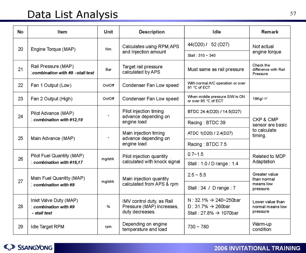
Data List AnalysisNo
20
Item
Engine Torque (MAP)
Unit
Description
Nm
Calculates using RPM,APS
and Injection amount
21
Rail Pressure (MAP)
:combination with #9 -stall test
22
Fan 1 Output (Low)
23
Fan 2 Output (High)
24
Pilot Advance (MAP)
: combination with #12,19
°
Main Advance (MAP)
°
25
26
Pilot Fuel Quantity (MAP)
: combination with #16,17
27
Main Fuel Quantity (MAP)
: combination with #9
28
Inlet Valve Duty (MAP)
: combination with #9
Idle Target RPM
Idle
44(D20) / 52 (D27)
Stall : 310 ~ 340
Target rail pressure
calculated by APS
Must same as rail pressure
On/Off
Condenser Fan Low speed
With normal A/C operation or over
91 ℃ of ECT
On/Off
Condenser Fan Low speed
When middle pressure S/W is ON
or over 95 ℃ of ECT
Pilot injection timing
advance depending on
engine load
BTDC 24.4(D20) / 14.5(D27)
Main injection timing
advance depending on
engine load
ATDC 1(D20) / 2.4(D27)
Pilot injection quantity
calculated with knock signal
0.7~1.5
Bar
mg/strk
mg/strk
%
- stall test
29
57
rpm
Racing : BTDC 39
Remark
Not actual
engine torque
Check the
difference with Rail
Pressure
19Kg/ ㎠
CKP & CMP
sensor are basic
to calculate
timing.
Racing : BTDC 7.5
Stall : 1.0 / D range : 1.4
Related to MDP
Adaptation
Stall : 34 / D range : 7
Greater value
than normal
means low
pressure.
IMV control duty, as Rail
Pressure (MAP) increases,
duty decreases.
N : 32.1% 240~250bar
D : 31.7% 260bar
Stall : 27.8% 1070bar
Lower value than
normal means low
pressure
Depending on engine
temperature and load
730 ~ 780
Warm-up
condition
Main injection quantity
calculated from APS & rpm
1
2.5 ~ 5.5
2006 INVITATIONAL TRAINING
58.
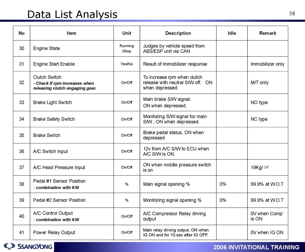
Data List AnalysisNo
Item
58
Unit
Description
Idle
Remark
30
Engine State
Running
/Stop
Judges by vehicle speed from
ABS/ESP unit via CAN
31
Engine Start Enable
Yes/No
Result of Immobilizer response
Immobilizer only
To increase rpm when clutch
release with neutral S/W off. ON
when depressed.
M/T only
Clutch Switch
32
- Check if rpm increases when
releasing clutch engaging gear.
On/Off
33
Brake Light Switch
On/Off
Main brake S/W signal.
ON when depressed.
NO type
34
Brake Safety Switch
On/Off
Monitoring S/W signal for main
S/W , ON when depressed.
NC type
35
Brake Switch
On/Off
Brake pedal status, ON when
depressed
36
A/C Switch Input
On/Off
12v from A/C S/W to ECU when
A/C S/W is ON.
37
A/C Head Pressure Input
On/Off
ON when middle pressure switch
is on
38
Pedal #1 Sensor Position
: combination with #39
%
Main signal opening %
0%
99.9% at W.O.T
39
Pedal #2 Sensor Position
%
Monitoring signal opening %
0%
99.9% at W.O.T
40
A/C Control Output
: combination with #36
On/Off
A/C Compressor Relay driving
output
0V when Comp’
is ON
41
Power Relay Output
On/Off
Main relay driving output, ON when
IG ON and for 10 sec after IG OFF.
0V when IG ON
1
19Kg/ ㎠
2006 INVITATIONAL TRAINING
59.
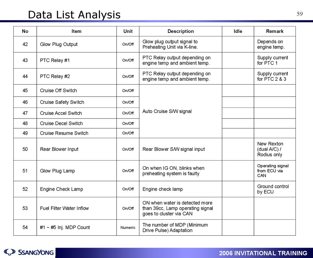
Data List AnalysisNo
Item
59
Unit
Description
Idle
Remark
42
Glow Plug Output
On/Off
Glow plug output signal to
Preheating Unit via K-line.
Depends on
engine temp.
43
PTC Relay #1
On/Off
PTC Relay output depending on
engine temp and ambient temp.
Supply current
for PTC 1
44
PTC Relay #2
On/Off
PTC Relay output depending on
engine temp and ambient temp.
Supply current
for PTC 2 & 3
45
Cruise Off Switch
On/Off
46
Cruise Safety Switch
On/Off
47
Cruise Accel Switch
On/Off
48
Cruise Decel Switch
On/Off
49
Cruise Resume Switch
On/Off
50
Rear Blower Input
On/Off
Rear Blower S/W signal input
New Rexton
(dual A/C) /
Rodius only
51
Glow Plug Lamp
On/Off
On when IG ON, blinks when
preheating system is faulty
Operating signal
from ECU via
CAN
52
Engine Check Lamp
On/Off
Engine check lamp
Ground control
by ECU
53
Fuel Filter Water Inflow
On/Off
ON when water is detected more
than 39cc, Lamp operating signal
goes to cluster via CAN
54
#1 ~ #5 Inj. MDP Count
Numeric
Auto Cruise S/W signal
The number of MDP (Minimum
Drive Pulse) Adaptation
1
2006 INVITATIONAL TRAINING