


 industry
Similar presentations:


AT - A4AF3. Automatic Transaxle
1.
AT - A4AF3Automatic Transaxle
(Presentation & Handout)
© HMC & KMC reserves all rights of disposal such as copying and passing on to third parties. This book should be used for the training purpose. 2005.01.07
2.
Appreance© HMC & KMC reserves all rights of disposal such as copying and passing on to third parties. This book should be used for the training purpose. 2005.01.07
AT - A4AF3
3.
Model codeAT - A4AF3
A 4 A F1
①
②
③
④
⑤
① : Type
A : Automatic
M : Manual
③ : Project name
A : Alpha
B : Beta
② : Speed
3 : 3rd speed
4 : 4th speed
5 : 5th speed
6 : 6th speed
④ : Drive type
F : Front
R : RR
4 : 4WD
⑤ : Development sequence
1,2,3,…
© HMC & KMC reserves all rights of disposal such as copying and passing on to third parties. This book should be used for the training purpose. 2005.01.07
4.
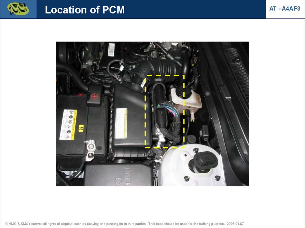
Location of PCM© HMC & KMC reserves all rights of disposal such as copying and passing on to third parties. This book should be used for the training purpose. 2005.01.07
AT - A4AF3
5.
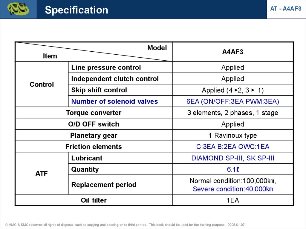
SpecificationAT - A4AF3
Model
Item
Control
Line pressure control
Applied
Independent clutch control
Applied
Skip shift control
Number of solenoid valves
ATF
A4AF3
Applied (4 ▶2, 3 ▶ 1)
6EA (ON/OFF:3EA PWM:3EA)
Torque converter
3 elements, 2 phases, 1 stage
O/D OFF switch
Applied
Planetary gear
1 Ravinoux type
Friction elements
C:3EA B:2EA OWC:1EA
Lubricant
DIAMOND SP-III, SK SP-III
Quantity
6.1ℓ
Replacement period
Oil filter
Normal condition:100,000㎞,
Severe condition:40,000㎞
1EA
© HMC & KMC reserves all rights of disposal such as copying and passing on to third parties. This book should be used for the training purpose. 2005.01.07
6.
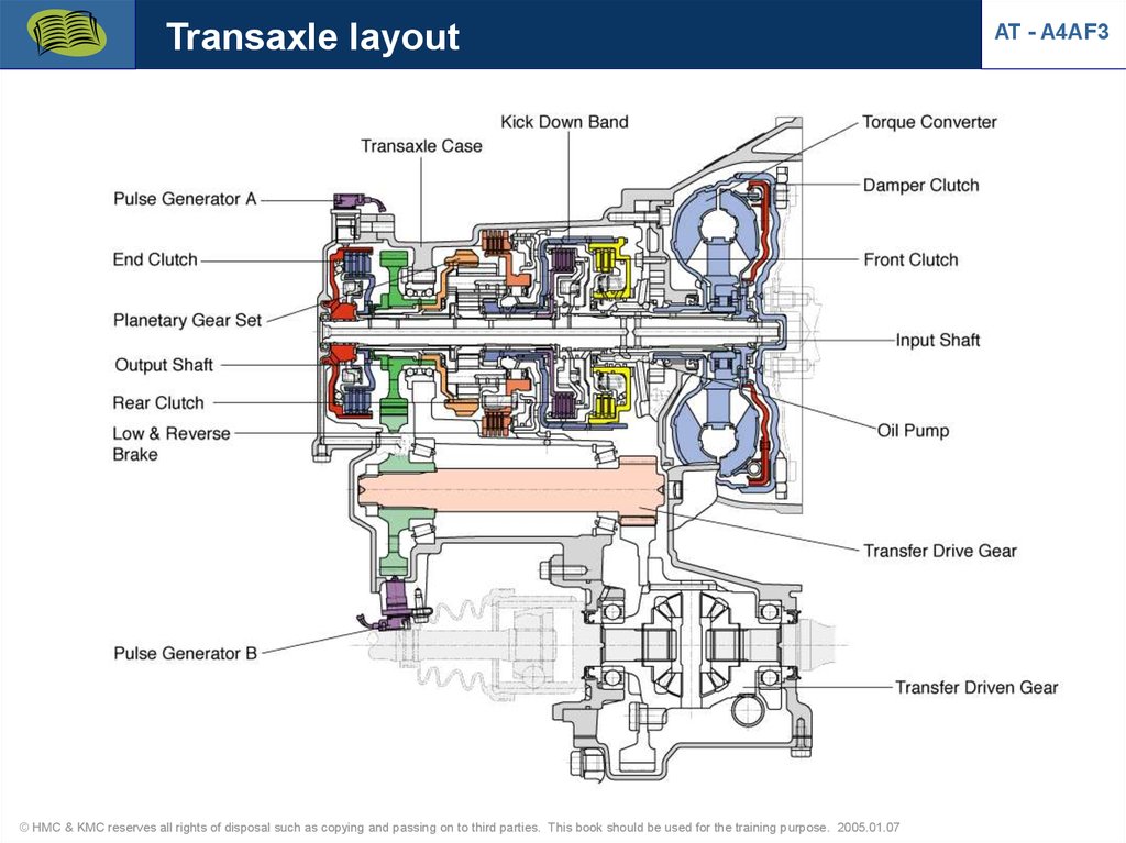
Transaxle layout© HMC & KMC reserves all rights of disposal such as copying and passing on to third parties. This book should be used for the training purpose. 2005.01.07
AT - A4AF3
7.
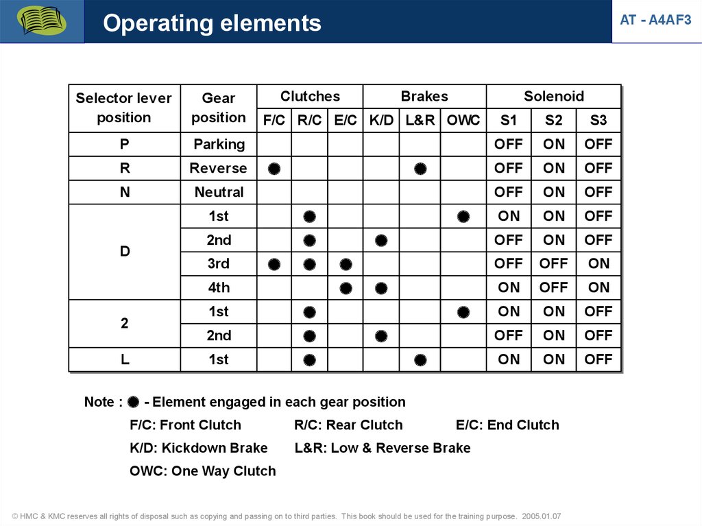
Operating elementsSelector lever
position
Gear
position
P
Parking
R
Reverse
N
Neutral
D
Clutches
L
Solenoid
2nd
4th
2
Brakes
F/C R/C E/C K/D L&R OWC
1st
3rd
AT - A4AF3
1st
2nd
1st
S1
S2
S3
OFF
ON
OFF
OFF
ON
OFF
OFF
ON
OFF
ON
ON
OFF
OFF
ON
OFF
OFF
OFF
ON
ON
OFF
ON
ON
ON
OFF
OFF
ON
OFF
ON
ON
OFF
Note : ● - Element engaged in each gear position
F/C: Front Clutch
R/C: Rear Clutch
E/C: End Clutch
K/D: Kickdown Brake
L&R: Low & Reverse Brake
OWC: One Way Clutch
© HMC & KMC reserves all rights of disposal such as copying and passing on to third parties. This book should be used for the training purpose. 2005.01.07
8.
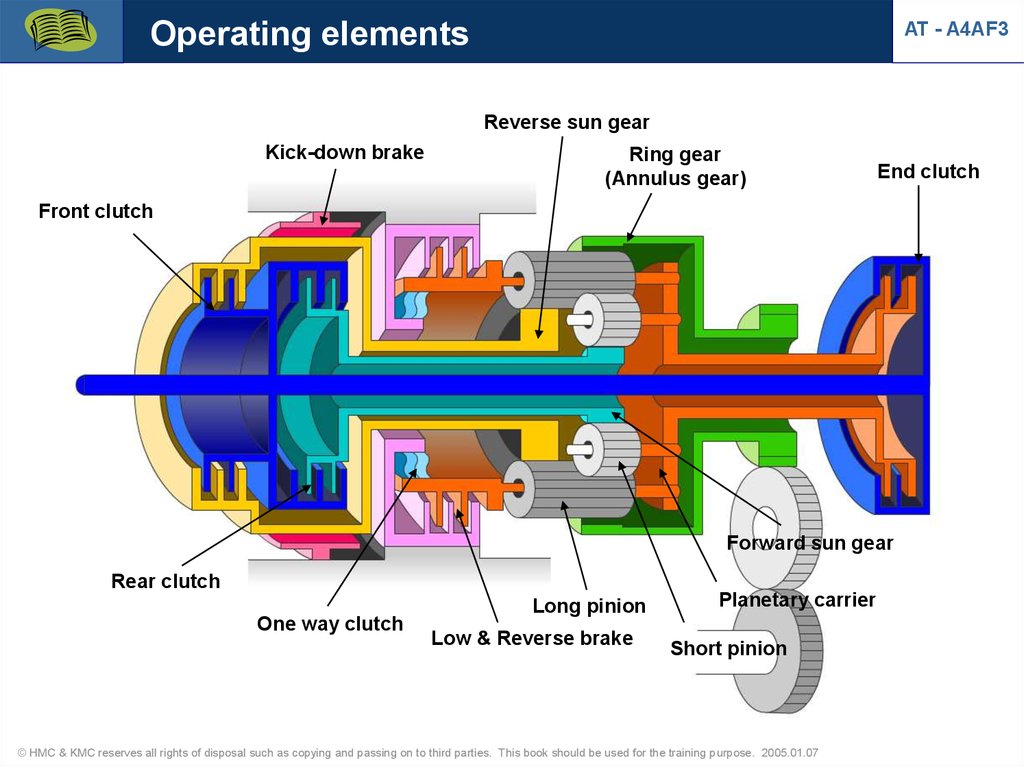
Operating elementsAT - A4AF3
Reverse sun gear
Kick-down brake
Ring gear
(Annulus gear)
End clutch
Front clutch
Forward sun gear
Rear clutch
One way clutch
Long pinion
Low & Reverse brake
Planetary carrier
Short pinion
© HMC & KMC reserves all rights of disposal such as copying and passing on to third parties. This book should be used for the training purpose. 2005.01.07
9.
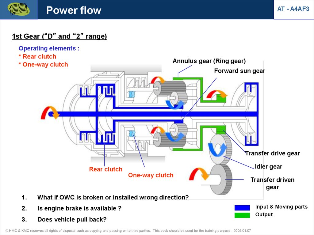
Power flowAT - A4AF3
1st Gear (“D” and “2” range)
Operating elements :
* Rear clutch
* One-way clutch
Annulus gear (Ring gear)
Forward sun gear
Transfer drive gear
Idler gear
Rear clutch
One-way clutch
1.
What if OWC is broken or installed wrong direction?
2.
Is engine brake is available ?
3.
Does vehicle pull back?
Transfer driven
gear
© HMC & KMC reserves all rights of disposal such as copying and passing on to third parties. This book should be used for the training purpose. 2005.01.07
Input & Moving parts
Output
10.
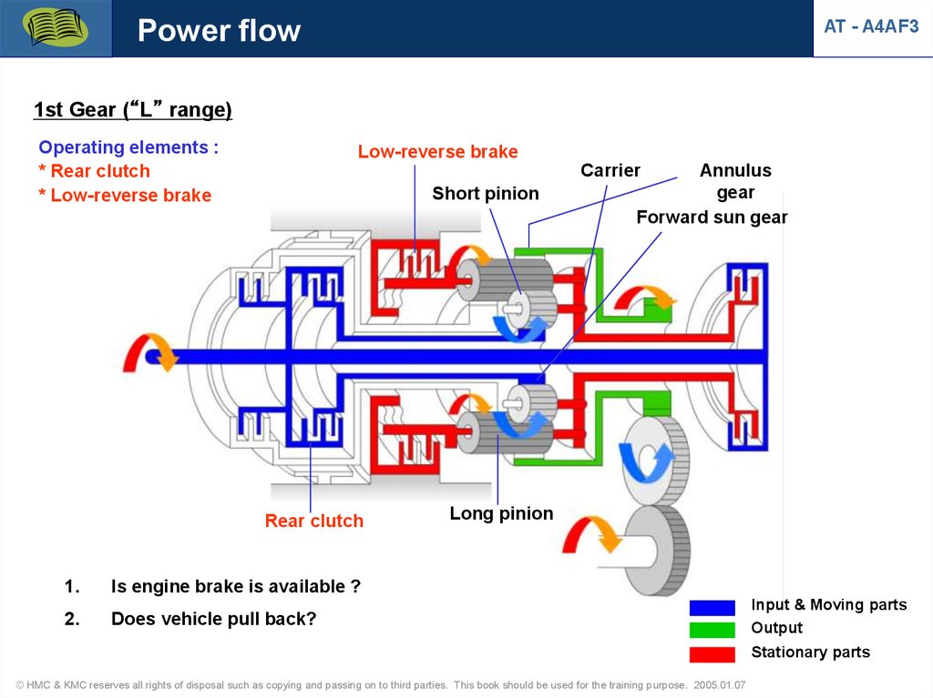
Power flowAT - A4AF3
1st Gear (“L” range)
Operating elements :
* Rear clutch
* Low-reverse brake
Low-reverse brake
Carrier
Short pinion
Rear clutch
1.
Is engine brake is available ?
2.
Does vehicle pull back?
Annulus
gear
Forward sun gear
Long pinion
Input & Moving parts
Output
Stationary parts
© HMC & KMC reserves all rights of disposal such as copying and passing on to third parties. This book should be used for the training purpose. 2005.01.07
11.
Power flowAT - A4AF3
2nd Gear (“D” and “2” range)
Operating elements :
* Rear clutch
* Kickdown brake
Kickdown brake
Annulus gear
Short pinion
Forward sun gear
Rear clutch
1.
Long pinion
Does vehicle pull back?
Input & Moving parts
Output
Stationary parts
© HMC & KMC reserves all rights of disposal such as copying and passing on to third parties. This book should be used for the training purpose. 2005.01.07
12.
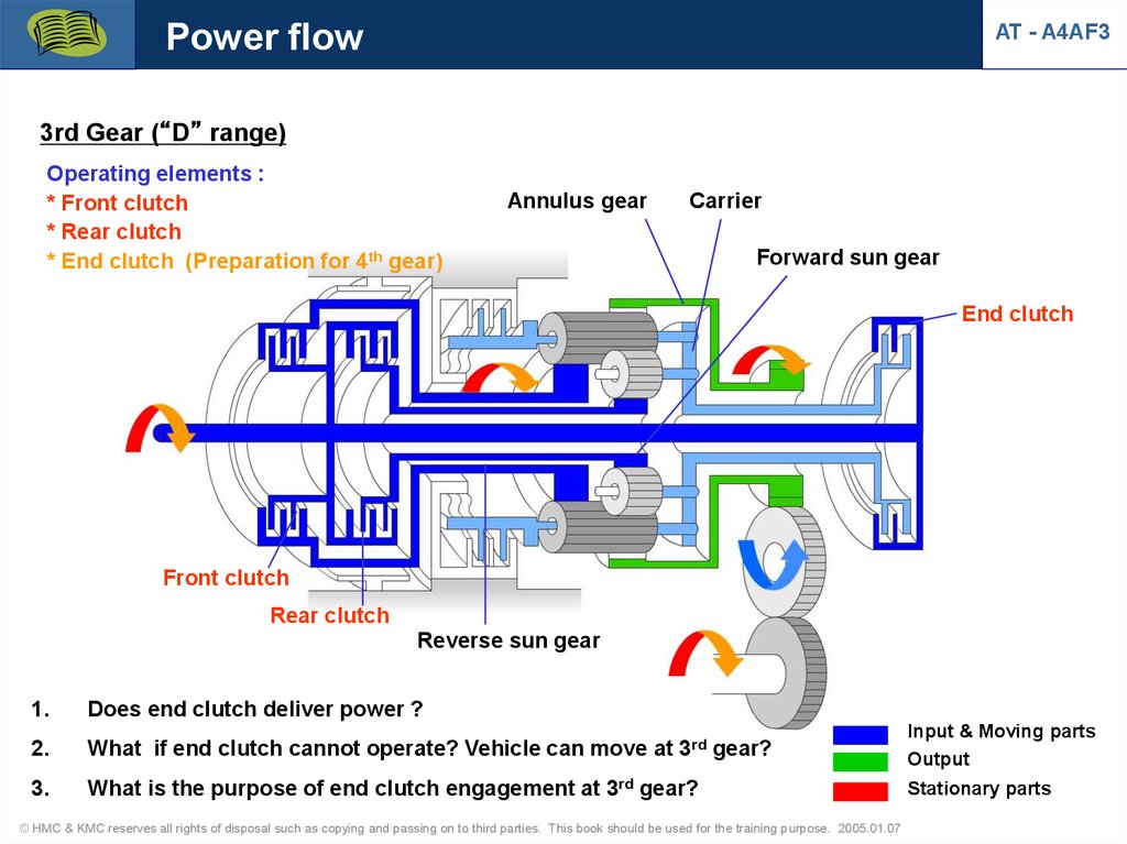
Power flowAT - A4AF3
3rd Gear (“D” range)
Operating elements :
* Front clutch
* Rear clutch
* End clutch (Preparation for 4th gear)
Annulus gear
Carrier
Forward sun gear
End clutch
Front clutch
Rear clutch
Reverse sun gear
1.
Does end clutch deliver power ?
2.
What if end clutch cannot operate? Vehicle can move at 3rd gear?
Input & Moving parts
Output
3.
What is the purpose of end clutch engagement at 3rd gear?
Stationary parts
© HMC & KMC reserves all rights of disposal such as copying and passing on to third parties. This book should be used for the training purpose. 2005.01.07
13.
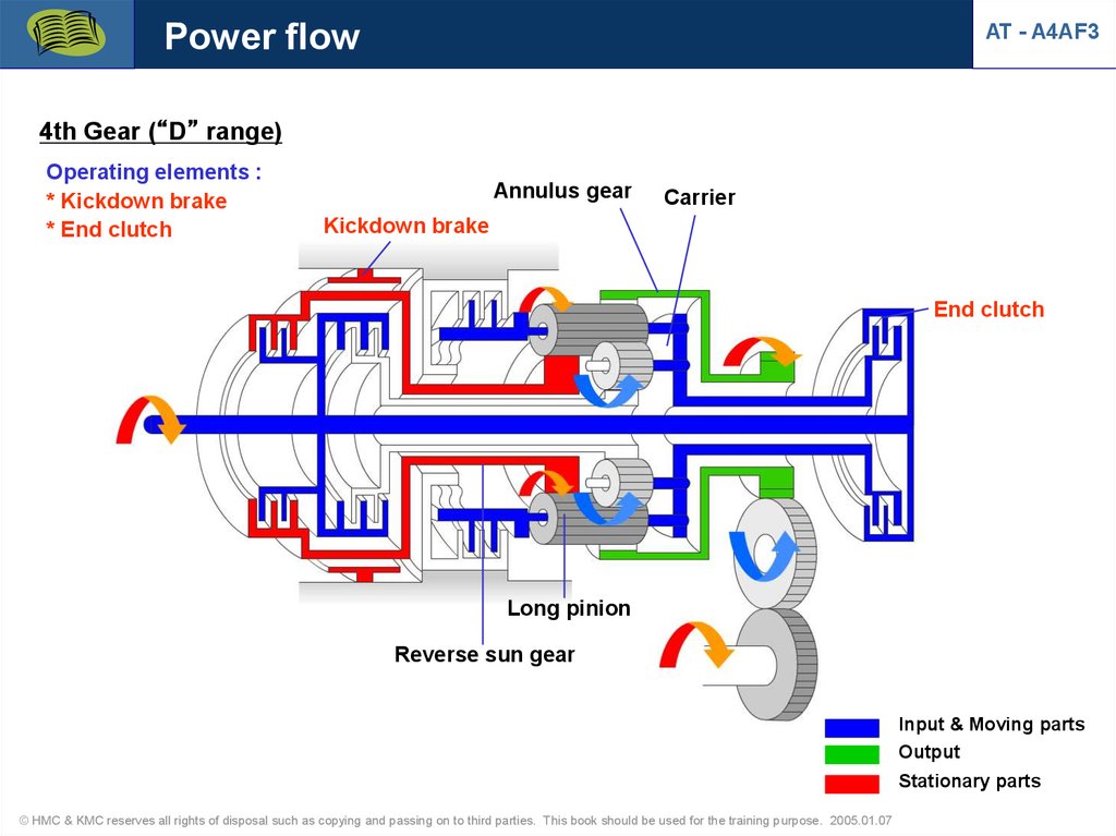
Power flowAT - A4AF3
4th Gear (“D” range)
Operating elements :
* Kickdown brake
* End clutch
Annulus gear
Carrier
Kickdown brake
End clutch
Long pinion
Reverse sun gear
Input & Moving parts
Output
Stationary parts
© HMC & KMC reserves all rights of disposal such as copying and passing on to third parties. This book should be used for the training purpose. 2005.01.07
14.
Power flowAT - A4AF3
Reverse range
Operating elements :
* Front clutch
* Low-reverse brake
Low-reverse brake
Annulus gear
Carrier
Front clutch
Reverse sun gear
Long pinion
Input & Moving parts
Output
Stationary parts
© HMC & KMC reserves all rights of disposal such as copying and passing on to third parties. This book should be used for the training purpose. 2005.01.07
15.
Thrust bearings and racesAT - A4AF3
Fiber
#13
#12
#11
#10
#9
#8 #7
#6 #5
#4
#3
© HMC & KMC reserves all rights of disposal such as copying and passing on to third parties. This book should be used for the training purpose. 2005.01.07
Fiber
#2
#1
16.
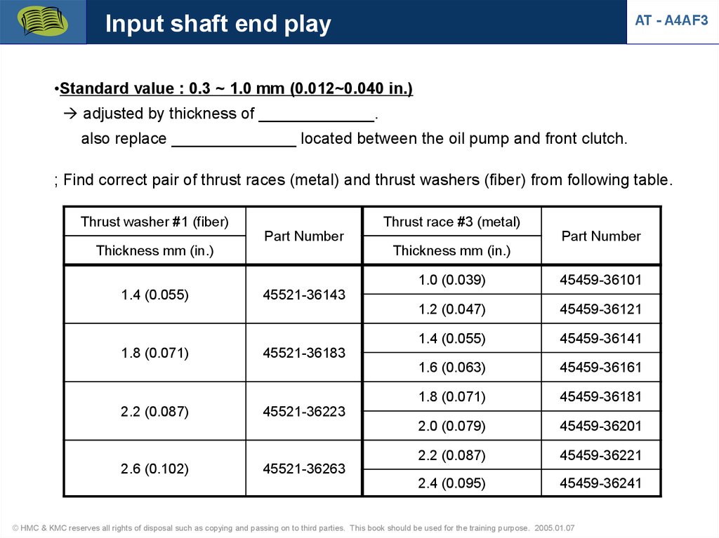
Input shaft end playAT - A4AF3
•Standard value : 0.3 ~ 1.0 mm (0.012~0.040 in.)
adjusted by thickness of _____________.
also replace ______________ located between the oil pump and front clutch.
; Find correct pair of thrust races (metal) and thrust washers (fiber) from following table.
Thrust washer #1 (fiber)
Thrust race #3 (metal)
Part Number
Thickness mm (in.)
1.4 (0.055)
1.8 (0.071)
2.2 (0.087)
2.6 (0.102)
Part Number
Thickness mm (in.)
1.0 (0.039)
45459-36101
1.2 (0.047)
45459-36121
1.4 (0.055)
45459-36141
1.6 (0.063)
45459-36161
1.8 (0.071)
45459-36181
2.0 (0.079)
45459-36201
2.2 (0.087)
45459-36221
2.4 (0.095)
45459-36241
45521-36143
45521-36183
45521-36223
45521-36263
© HMC & KMC reserves all rights of disposal such as copying and passing on to third parties. This book should be used for the training purpose. 2005.01.07
17.
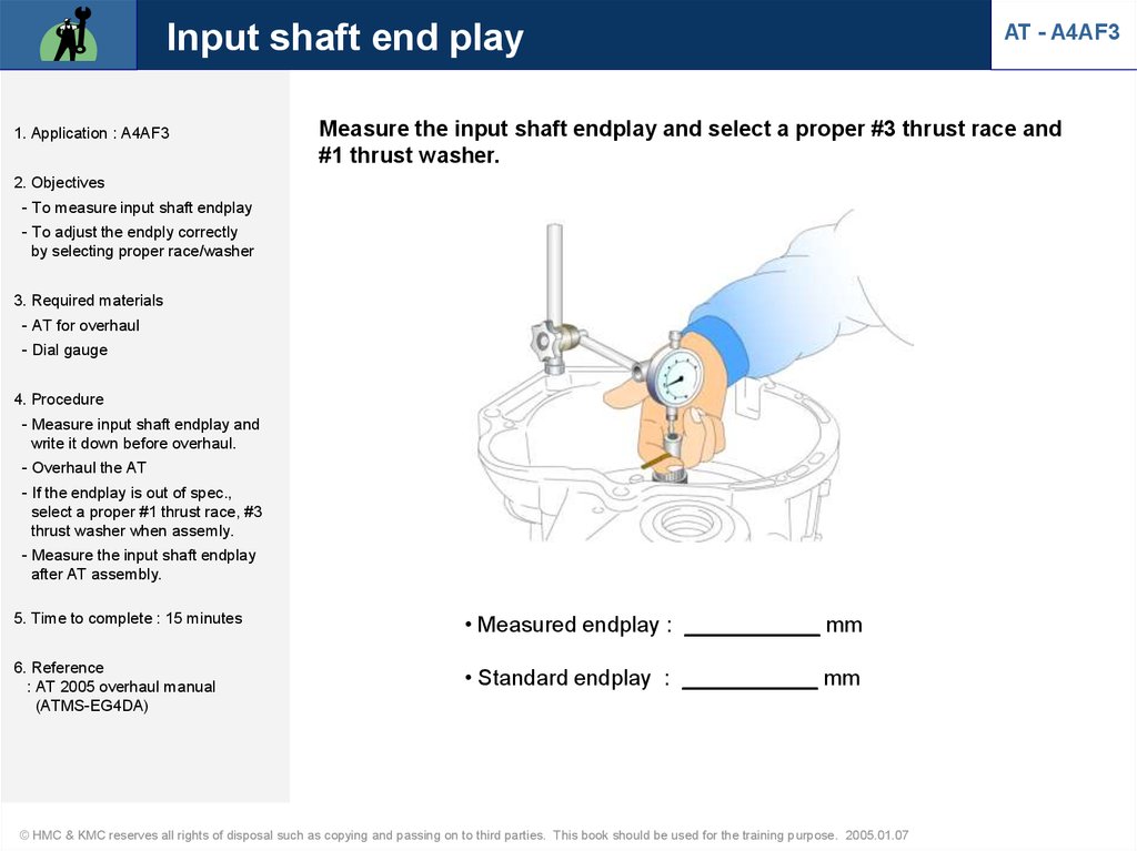
Input shaft end play1. Application : A4AF3
AT - A4AF3
Measure the input shaft endplay and select a proper #3 thrust race and
#1 thrust washer.
2. Objectives
- To measure input shaft endplay
- To adjust the endply correctly
by selecting proper race/washer
3. Required materials
- AT for overhaul
- Dial gauge
4. Procedure
- Measure input shaft endplay and
write it down before overhaul.
- Overhaul the AT
- If the endplay is out of spec.,
select a proper #1 thrust race, #3
thrust washer when assemly.
- Measure the input shaft endplay
after AT assembly.
5. Time to complete : 15 minutes
• Measured endplay : ___________ mm
6. Reference
: AT 2005 overhaul manual
(ATMS-EG4DA)
• Standard endplay : ___________ mm
© HMC & KMC reserves all rights of disposal such as copying and passing on to third parties. This book should be used for the training purpose. 2005.01.07
18.
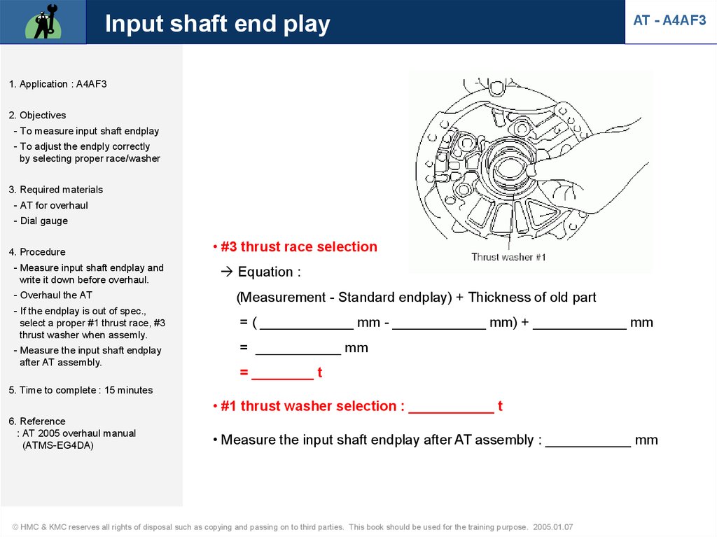
Input shaft end playAT - A4AF3
1. Application : A4AF3
2. Objectives
- To measure input shaft endplay
- To adjust the endply correctly
by selecting proper race/washer
3. Required materials
- AT for overhaul
- Dial gauge
4. Procedure
- Measure input shaft endplay and
write it down before overhaul.
- Overhaul the AT
- If the endplay is out of spec.,
select a proper #1 thrust race, #3
thrust washer when assemly.
- Measure the input shaft endplay
after AT assembly.
• #3 thrust race selection
Equation :
(Measurement - Standard endplay) + Thickness of old part
= ( ____________ mm - ____________ mm) + ____________ mm
= ___________ mm
= ________ t
5. Time to complete : 15 minutes
• #1 thrust washer selection : ___________ t
6. Reference
: AT 2005 overhaul manual
(ATMS-EG4DA)
• Measure the input shaft endplay after AT assembly : ___________ mm
© HMC & KMC reserves all rights of disposal such as copying and passing on to third parties. This book should be used for the training purpose. 2005.01.07
19.
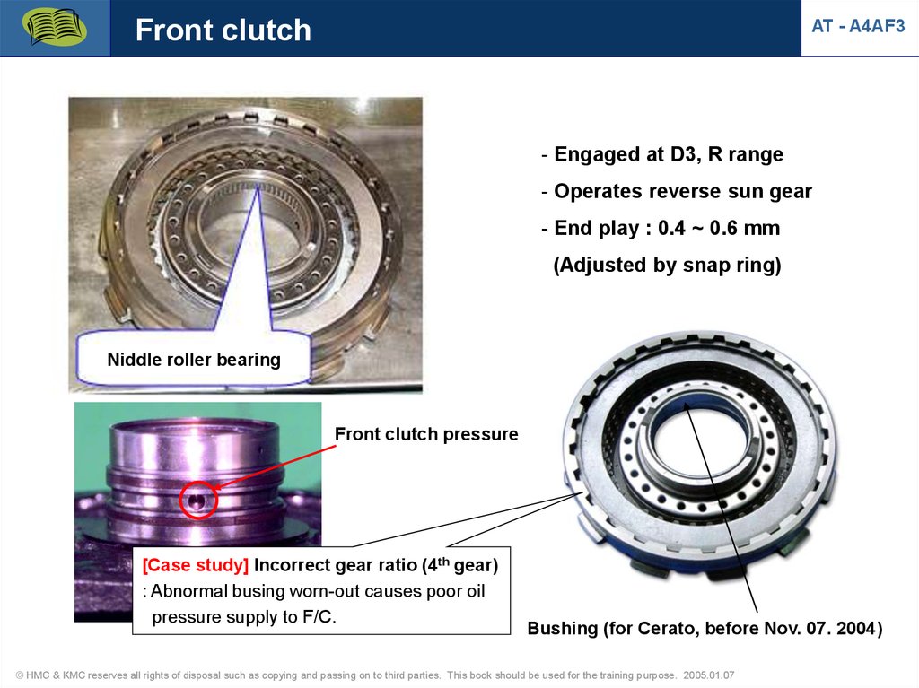
Front clutchAT - A4AF3
- Engaged at D3, R range
- Operates reverse sun gear
- End play : 0.4 ~ 0.6 mm
(Adjusted by snap ring)
Niddle roller bearing
Front clutch pressure
[Case study] Incorrect gear ratio (4th gear)
: Abnormal busing worn-out causes poor oil
pressure supply to F/C.
Bushing (for Cerato, before Nov. 07. 2004)
© HMC & KMC reserves all rights of disposal such as copying and passing on to third parties. This book should be used for the training purpose. 2005.01.07
20.
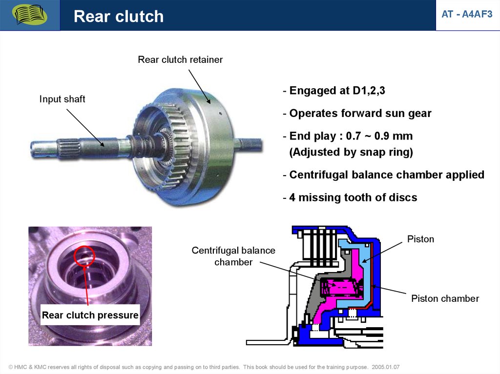
Rear clutchAT - A4AF3
Rear clutch retainer
- Engaged at D1,2,3
Input shaft
- Operates forward sun gear
- End play : 0.7 ~ 0.9 mm
(Adjusted by snap ring)
- Centrifugal balance chamber applied
- 4 missing tooth of discs
Piston
Centrifugal balance
chamber
Piston chamber
Rear clutch pressure
© HMC & KMC reserves all rights of disposal such as copying and passing on to third parties. This book should be used for the training purpose. 2005.01.07
21.
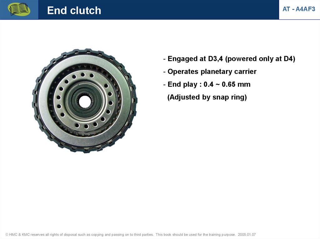
End clutchAT - A4AF3
- Engaged at D3,4 (powered only at D4)
- Operates planetary carrier
- End play : 0.4 ~ 0.65 mm
(Adjusted by snap ring)
© HMC & KMC reserves all rights of disposal such as copying and passing on to third parties. This book should be used for the training purpose. 2005.01.07
22.
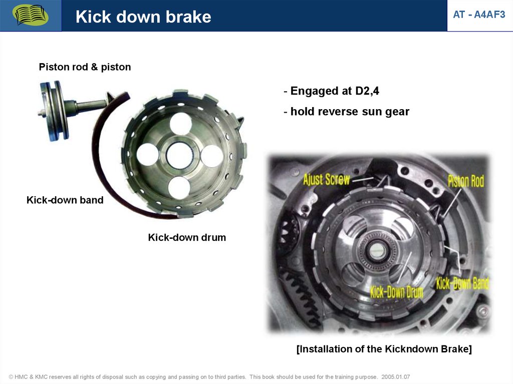
Kick down brakeAT - A4AF3
Piston rod & piston
- Engaged at D2,4
- hold reverse sun gear
Kick-down band
Kick-down drum
[Installation of the Kickndown Brake]
© HMC & KMC reserves all rights of disposal such as copying and passing on to third parties. This book should be used for the training purpose. 2005.01.07
23.
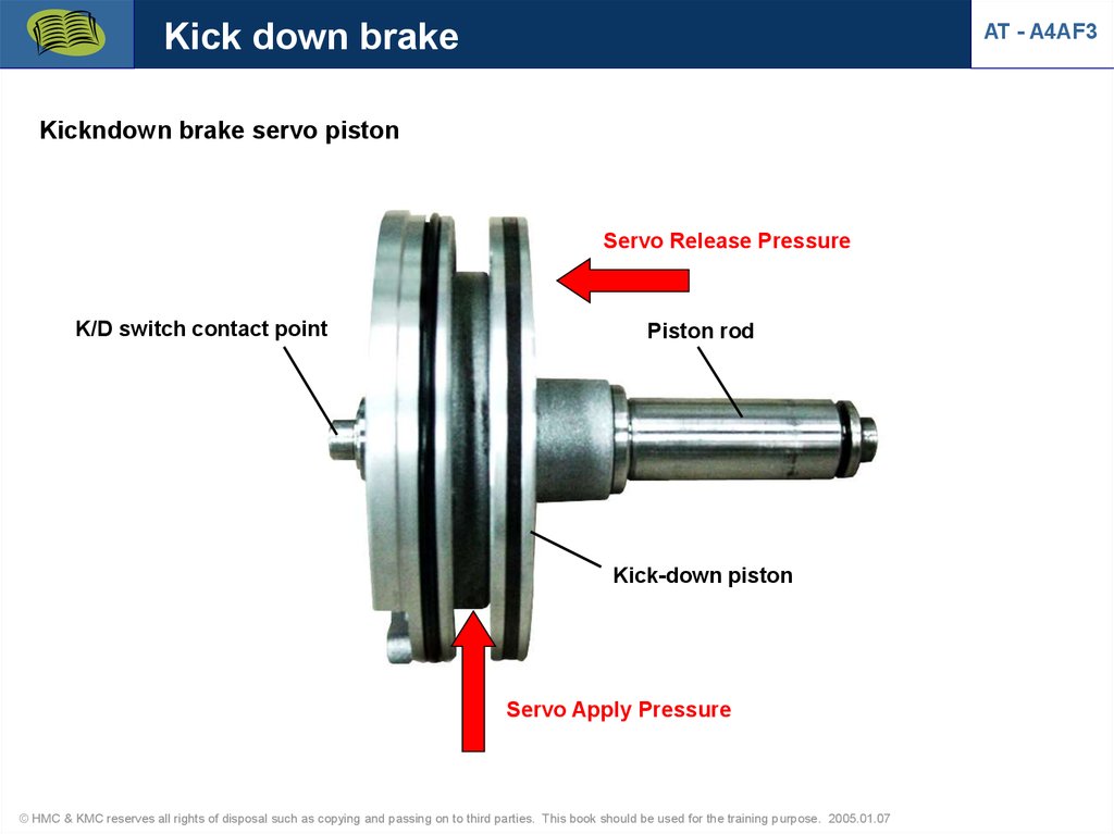
Kick down brakeAT - A4AF3
Kickndown brake servo piston
Servo Release Pressure
K/D switch contact point
Piston rod
Kick-down piston
Servo Apply Pressure
© HMC & KMC reserves all rights of disposal such as copying and passing on to third parties. This book should be used for the training purpose. 2005.01.07
24.
Kick down brake adjustmentAT - A4AF3
■ Case Study
1) Symptom
- Shift shock at 1st 2nd gear
2) DTC: None
3) Cause: Kickdown brake
Service Point
No.
Cause
Symptom
Analysis
Remedy
Remarks
1
Looseness of Engine RPM sharply
K/D band increase (Run-up)
F/C is released prior to
K/D band engaged.
(1st gear state)
Adjust K/D
servo rod
See note
2
- Shock when shift
Air exhaust
from 1st to 2nd and
plug cap
from 3rd to 4th gear
separated
- 3rd gear hold
K/D piston can't move
forward.
(K/D band slippage)
Checking method :
Replace air
repeated shifting from
exhaust plug
3rd to 4th or opposite
cap
(O/D sw ON-OFF)
© HMC & KMC reserves all rights of disposal such as copying and passing on to third parties. This book should be used for the training purpose. 2005.01.07
25.
Kick down brake adjustmentAT - A4AF3
* Adjustment procedure
① Loosen the adjust screw lock
nut
② Tighten and loosen the adjust screw (2 times, Torque : 5Nm, 50kgcm)
© HMC & KMC reserves all rights of disposal such as copying and passing on to third parties. This book should be used for the training purpose. 2005.01.07
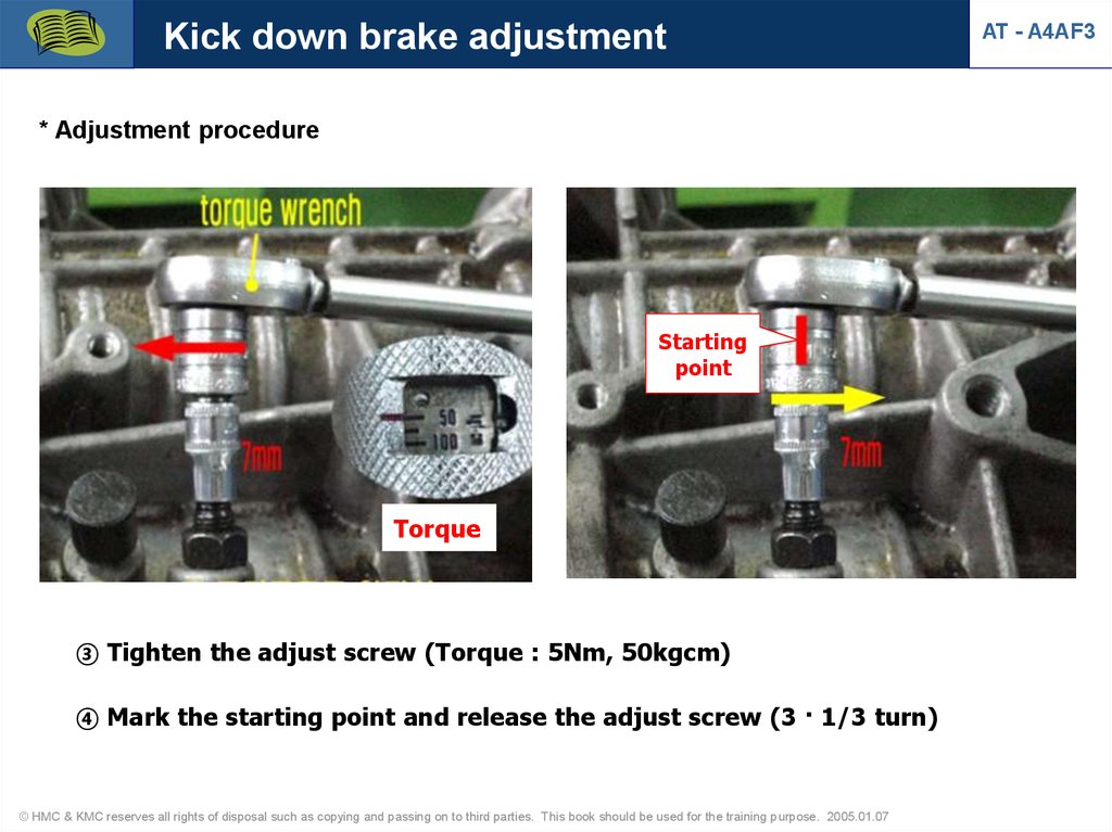
26.
Kick down brake adjustment* Adjustment procedure
Starting
point
Torque
③ Tighten the adjust screw (Torque : 5Nm, 50kgcm)
④ Mark the starting point and release the adjust screw (3 · 1/3 turn)
© HMC & KMC reserves all rights of disposal such as copying and passing on to third parties. This book should be used for the training purpose. 2005.01.07
AT - A4AF3
27.
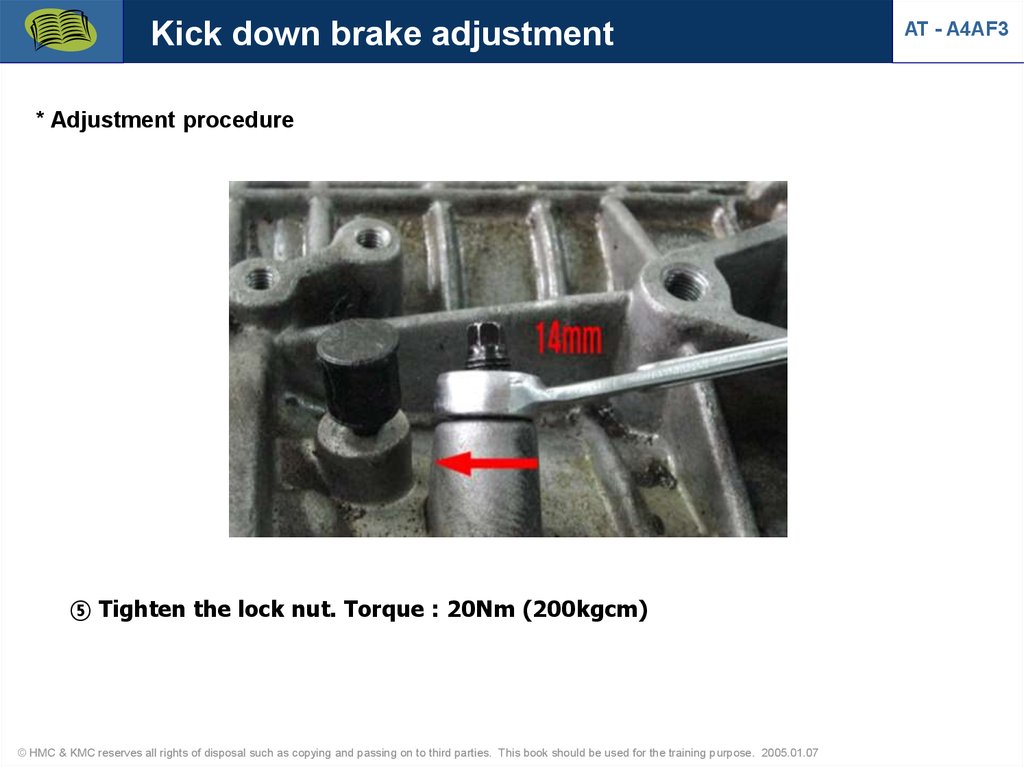
Kick down brake adjustment* Adjustment procedure
⑤ Tighten the lock nut. Torque : 20Nm (200kgcm)
© HMC & KMC reserves all rights of disposal such as copying and passing on to third parties. This book should be used for the training purpose. 2005.01.07
AT - A4AF3
28.
Low & Reverse brakeAT - A4AF3
Center support
- Engaged at L, R range
- holds planetary carrier
- End play : 0.675 ~ 0.987 mm
(Adjusted by pressure plate)
Wave spring
Hydraulic pressure
LR brake pision
[Case study] R range shift shock broken wave spring
© HMC & KMC reserves all rights of disposal such as copying and passing on to third parties. This book should be used for the training purpose. 2005.01.07
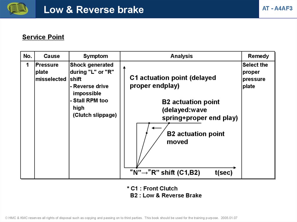
29.
Low & Reverse brakeAT - A4AF3
Service Point
No.
1
Cause
Symptom
Pressure
Shock generated
plate
during "L" or "R"
misselected shift
- Reverse drive
impossible
- Stall RPM too
high
(Clutch slippage)
Analysis
Remedy
C1 actuation point (delayed
proper endplay)
B2 actuation point
(delayed:wave
spring+proper end play)
B2 actuation point
moved
“N”→”R” shift (C1,B2)
t(sec)
* C1 : Front Clutch
B2 : Low & Reverse Brake
© HMC & KMC reserves all rights of disposal such as copying and passing on to third parties. This book should be used for the training purpose. 2005.01.07
Select the
proper
pressure
plate
30.
One way clutchAT - A4AF3
Annulus gear
Short pinion
Sprag
Long pinion
Free
Inner race
(Center support)
Lock
Outer race
(planetary gear carrier)
Carrier
Forward sun gear
Service Point
No.
1
Cause
Symptom
Analysis
O.W.C wear Forward drive Planetary carrier
or damaged
impossible
rotates reverse
Remedy
Remarks
Checking method :
Replace
Drive is possible at "L"
O.W.C
range
© HMC & KMC reserves all rights of disposal such as copying and passing on to third parties. This book should be used for the training purpose. 2005.01.07
31.
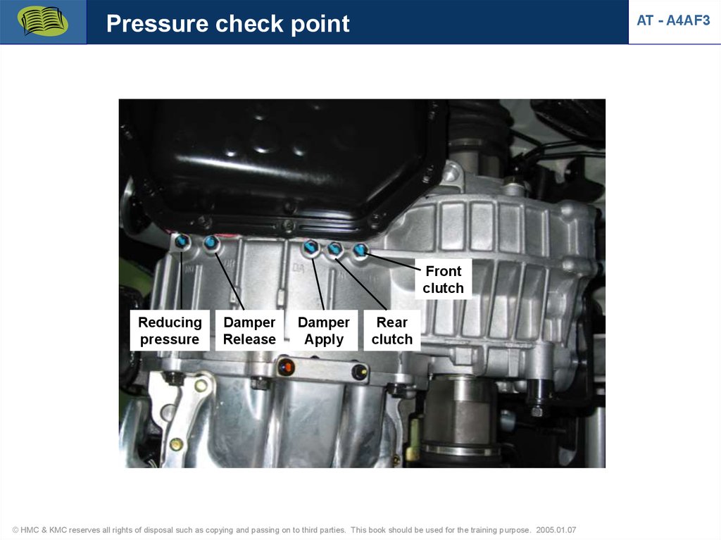
Pressure check pointAT - A4AF3
Front
clutch
Reducing
pressure
Damper
Release
Damper
Apply
Rear
clutch
© HMC & KMC reserves all rights of disposal such as copying and passing on to third parties. This book should be used for the training purpose. 2005.01.07
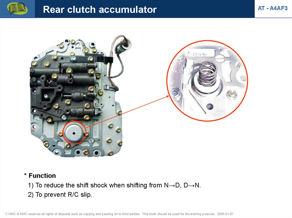
32.
Rear clutch accumulator* Function
1) To reduce the shift shock when shifting from N→D, D→N.
2) To prevent R/C slip.
© HMC & KMC reserves all rights of disposal such as copying and passing on to third parties. This book should be used for the training purpose. 2005.01.07
AT - A4AF3
33.
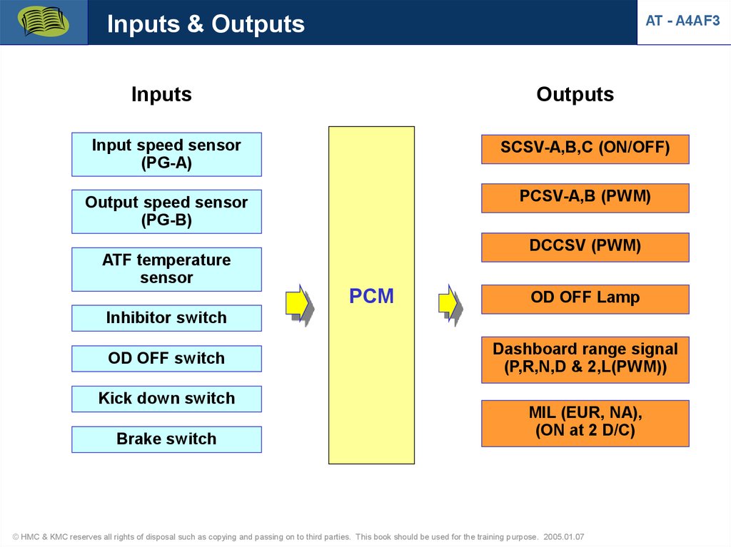
Inputs & OutputsAT - A4AF3
Inputs
Outputs
Input speed sensor
(PG-A)
SCSV-A,B,C (ON/OFF)
Output speed sensor
(PG-B)
PCSV-A,B (PWM)
DCCSV (PWM)
ATF temperature
sensor
PCM
OD OFF Lamp
Inhibitor switch
OD OFF switch
Kick down switch
Brake switch
Dashboard range signal
(P,R,N,D & 2,L(PWM))
MIL (EUR, NA),
(ON at 2 D/C)
© HMC & KMC reserves all rights of disposal such as copying and passing on to third parties. This book should be used for the training purpose. 2005.01.07
34.
Input speed sensor (PG-A)Input speed sensor
(PG-A)
• PG-A detects _________________ speed.
• Sensor resistance : 215~275Ω (20˚C)
© HMC & KMC reserves all rights of disposal such as copying and passing on to third parties. This book should be used for the training purpose. 2005.01.07
AT - A4AF3
35.
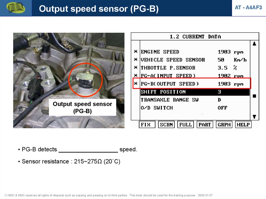
Output speed sensor (PG-B)Output speed sensor
(PG-B)
• PG-B detects __________________ speed.
• Sensor resistance : 215~275Ω (20˚C)
© HMC & KMC reserves all rights of disposal such as copying and passing on to third parties. This book should be used for the training purpose. 2005.01.07
AT - A4AF3
36.
Output waveformAT - A4AF3
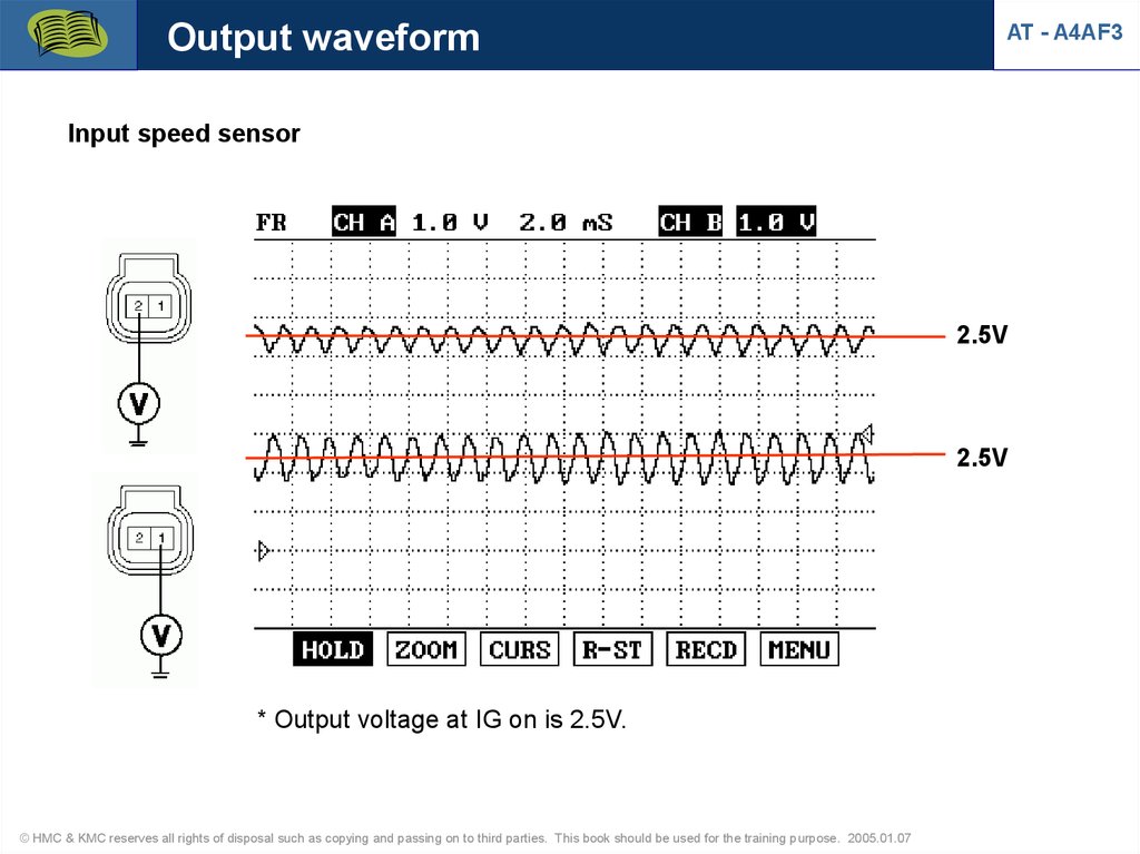
Input speed sensor
2.5V
2.5V
* Output voltage at IG on is 2.5V.
© HMC & KMC reserves all rights of disposal such as copying and passing on to third parties. This book should be used for the training purpose. 2005.01.07
37.
Diagnosis (input speed sensor)AT - A4AF3
* Rationality
Component
System
Fault Code
Description
Malfunction
Criteria
Threshold
Filtering
Time
MIL On
Input speed
sensor
P0716
Rationality high
Input speed
Input speed >
8000[rpm]
1[sec]
2drv.
cycle
Test Condition
Fail safety
Battery voltage >=9[V]
D: 3rd gear fix, 2,L: 2nd gear fix, damper open.
© HMC & KMC reserves all rights of disposal such as copying and passing on to third parties. This book should be used for the training purpose. 2005.01.07
38.
Diagnosis (input speed sensor)AT - A4AF3
* Input speed sensor open
Component
System
Fault Code
Description
Malfunction
Criteria
Threshold
Filtering Time
MIL On
Input speed
sensor
P0717
No Signal
Input speed
Input speed = 0
1[sec]
2drv.
cycle
Test Condition
Fail safety
Battery voltage >= 9[V]
Inhibitor switch = D, 2, L (No error)
Output speed > 1000[rpm]
Engine speed > 3000[rpm] (No error) (Only 1st gear)
D: 3rd gear fix, 2,L: 2nd gear fix, damper open.
© HMC & KMC reserves all rights of disposal such as copying and passing on to third parties. This book should be used for the training purpose. 2005.01.07
39.
Diagnosis (output speed sensor)AT - A4AF3
* Output speed sensor open
Component
System
Fault Code
Description
Malfunction
Criteria
Threshold
Filtering Time
MIL On
Output speed
sensor
P0722
No signal
Output speed
Output speed = 0
6.6[sec]
5.1[sec]
2drv. cycle
Test Condition
Fail safety
Battery voltage >=9V
Current gear = 1 and Inhibitor switch : D, 2, L (No error)
Brake Off (No Error)
Throttle opening > 14.9[%] (No error) and
Engine speed > 3500[rpm] (No error)
Time Delay : 1.6 sec Filter Time : 5 sec
OR
Battery voltage >=9V
Current gear > 1 and Inhibitor switch : D, 2 (No error)
Brake Off (No Error)
Input speed > 1500[rpm] (No error) or
Engine speed > 3000[rpm] (No error)
Time Delay : 100 msec Filter Time : 5 sec
Substitute Output speed (Vehicle speed or input speed signal),
D: 3rd gear fix, 2,L: 2nd gear fix, damper open.
© HMC & KMC reserves all rights of disposal such as copying and passing on to third parties. This book should be used for the training purpose. 2005.01.07
40.
Failsafe (incorrect gear ratio)AT - A4AF3
* Gear ratio (1st gear speed)
Component
System
Fault Code
1 Gear ratio
P0731
Description
Malfunction
Criteria
Threshold
Rationality high
Proportionality check
between input speed
and
output speed
Input speed >
Synchron
speed
+ 200[rpm]
Filtering
MIL On
Time
1.0[sec]
Engine speed sensor, OTS, Solenoid, Position lever, Input speed sensor,
Output speed
sensor, CAN no error
Syncron speed is calculated turbine speed
Test Condition
Fail safety
The last shift was finished > 2[sec]
Oil temperature > -10[ºC]
Engine speed > 400[rpm]
Inhibitor switch : D, 2, L
Input speed > 300[rpm]
Output speed > 300[rpm]
Electrical Actuator off (Fixed 3rd gear, damper open)
© HMC & KMC reserves all rights of disposal such as copying and passing on to third parties. This book should be used for the training purpose. 2005.01.07
2drv.
cycle
41.
Failsafe (incorrect gear ratio)AT - A4AF3
* Gear ratio (2nd ~ 4th gear speed)
Component
System
Fault Code
2, 3, 4
Gear ratio
P0732(2nd)
P0733(3rd)
P0734(4th)
Description
Rationality
low / high
Malfunction
Criteria
Proportionality check
between input speed
and
output speed
Threshold
Input speed >
Synchron
speed
± 200[rpm]
Filtering
MIL On
Time
1.0[sec]
Engine speed sensor, OTS, Solenoid, Position lever, Input speed sensor,
Output speed
sensor, CAN no error
Syncron speed is calculated turbine speed
Test Condition
Fail safety
The last shift was finished > 2[sec]
Oil temperature > -10[ºC]
Engine speed > 400[rpm]
Inhibitor switch : 4th(D),3rd(D),2nd(2)
Input speed > 300[rpm]
Output speed > 600[rpm]
Electrical Actuator off (Fixed 3rd gear, damper open)
© HMC & KMC reserves all rights of disposal such as copying and passing on to third parties. This book should be used for the training purpose. 2005.01.07
2drv.
cycle
42.
Kick-down switchAT - A4AF3
Shift
position
K/D
switch
1st gear
______
2nd gear
______
3rd gear
______
4th gear
______
© HMC & KMC reserves all rights of disposal such as copying and passing on to third parties. This book should be used for the training purpose. 2005.01.07
43.
Diagnosis (K/D switch)AT - A4AF3
* K/D switch open or short to GND (No MIL)
Failure
Detected Conditions
Failsafe
DTC
* Output speed > 900 rpm & ATF Temp. > 60℃
& Inhibitor S/W ≠ P,R,N & Engine speed > 400 rpm
No signal
GND Short
- S/W OFF continues for 2 seconds or more
from 5 seconds after shifting to 1st or 3rd gear
- S/W ON continues for 2 seconds or more
from 5 seconds after shifting to 2nd or 4th gear
Gear shifting is
available
© HMC & KMC reserves all rights of disposal such as copying and passing on to third parties. This book should be used for the training purpose. 2005.01.07
1709
44.
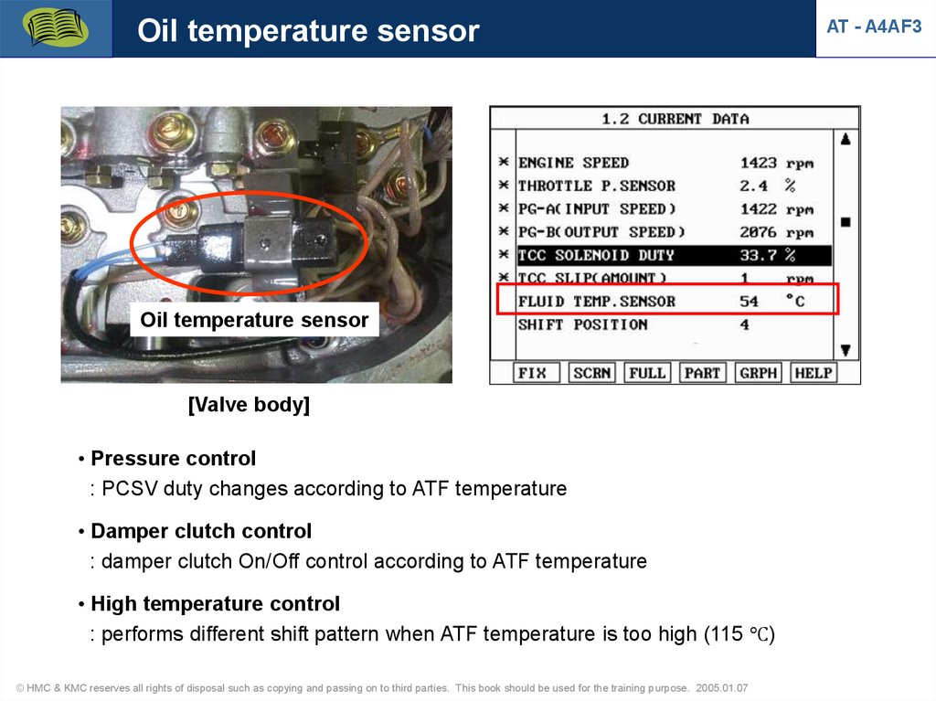
Oil temperature sensorOil temperature sensor
[Valve body]
• Pressure control
: PCSV duty changes according to ATF temperature
• Damper clutch control
: damper clutch On/Off control according to ATF temperature
• High temperature control
: performs different shift pattern when ATF temperature is too high (115 ℃)
© HMC & KMC reserves all rights of disposal such as copying and passing on to third parties. This book should be used for the training purpose. 2005.01.07
AT - A4AF3
45.
Diangosis (oil temperature sensor)AT - A4AF3
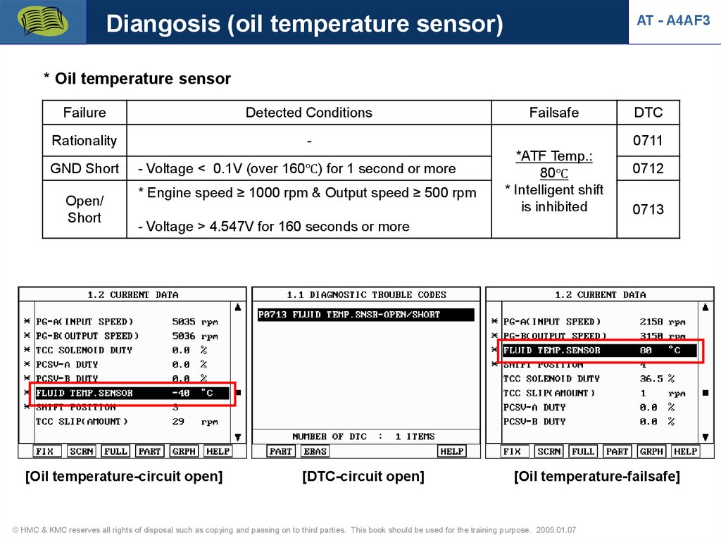
* Oil temperature sensor
Failure
Detected Conditions
Rationality
-
GND Short
Open/
Short
- Voltage < 0.1V (over 160℃) for 1 second or more
* Engine speed ≥ 1000 rpm & Output speed ≥ 500 rpm
Failsafe
DTC
0711
*ATF Temp.:
80℃
* Intelligent shift
is inhibited
0712
0713
- Voltage > 4.547V for 160 seconds or more
[Oil temperature-circuit open]
[DTC-circuit open]
[Oil temperature-failsafe]
© HMC & KMC reserves all rights of disposal such as copying and passing on to third parties. This book should be used for the training purpose. 2005.01.07
46.
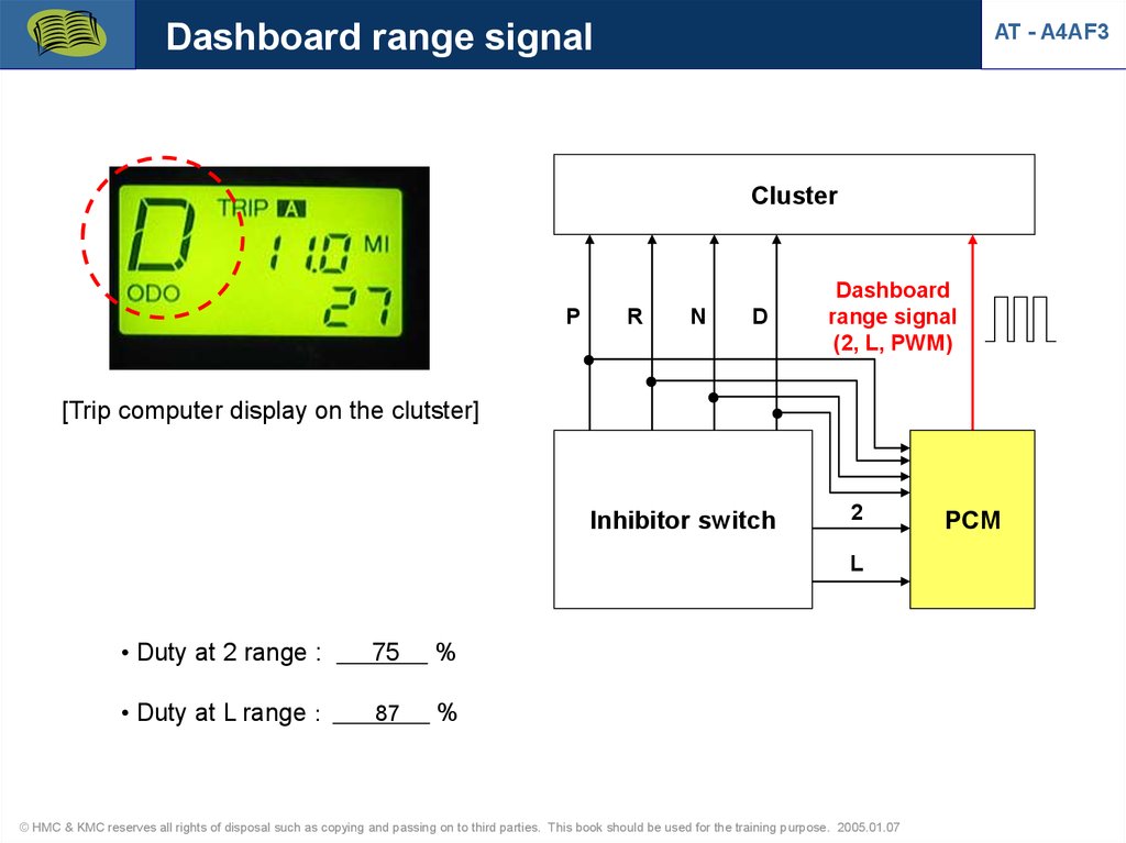
Dashboard range signalAT - A4AF3
Cluster
P
R
N
D
Dashboard
range signal
(2, L, PWM)
[Trip computer display on the clutster]
Inhibitor switch
2
L
• Duty at 2 range :
75
%
• Duty at L range :
87
%
© HMC & KMC reserves all rights of disposal such as copying and passing on to third parties. This book should be used for the training purpose. 2005.01.07
PCM
47.
Inhibitor switch (TR range sw)AT - A4AF3
* Shift pattern at each range
- D (O/D ON) : 1st 4th
- D (O/D OFF) : 1st 3rd 4th
- 2 : 1st 2nd 3rd t
- L L 1st 2nd
© HMC & KMC reserves all rights of disposal such as copying and passing on to third parties. This book should be used for the training purpose. 2005.01.07
48.
Diagnosis (Inhibitor switch)AT - A4AF3
* Rationality(Multiple signal)
Component
System
Fault Code
Description
Malfunction
Criteria
Inhibitor
switch
P0708
Rationality
Range switch
Test Condition
Fail safety
Threshold
Filtering
MIL On
Time
Multiple signals
30[sec]
are detected
Battery voltage >= 9[V]
Substitute position (the last valid value is still store)
Fix 3 gear when error occurred at IG Key On.
© HMC & KMC reserves all rights of disposal such as copying and passing on to third parties. This book should be used for the training purpose. 2005.01.07
2drv.
cycle
49.
Diagnosis (Inhibitor switch)AT - A4AF3
* Inhibitor switch open
Component
System
Fault Code
Description
Malfunction
Criteria
Threshold
Inhibitor
switch
P0707
Lack of circuit
continuity
Range switch
No signal is
detected
Test Condition
Fail safety
Filtering
MIL On
Time
30[sec]
Battery voltage >= 9[V]
Engine speed > 500[rpm] (No error)
Substitute position (the last valid value is still store)
Fix 3 gear when error occurred at IG Key On.
© HMC & KMC reserves all rights of disposal such as copying and passing on to third parties. This book should be used for the training purpose. 2005.01.07
2drv.
cycle
50.
Solenoid valvesSCSV-B
AT - A4AF3
SCSV-A
1. Type
DCCSV
PCSV-A
PCSV-B
- On/Off control
:
- PWM control (35Hz)
:
2. Control elements
- PCSV-A
: F/C, E/C, KD/B, LR/B
SCSV-C
- PCSV-B : _______
- SCSV-C : _______
- SCSV : Shift Control Solenoid Valve
- PCSV : Pressure Control Solenoid Valve
- DCCSV : Damper Clutch Control Solenoid Valve
© HMC & KMC reserves all rights of disposal such as copying and passing on to third parties. This book should be used for the training purpose. 2005.01.07
51.
Solenoid valvesAT - A4AF3
• Operation table at D range (SCSV-A,B,C)
Shift control solenoid valve
Operation
Position
A
B
C
1st gear
ON
ON
OFF
2nd gear
OFF
ON
OFF
3rd gear
OFF
OFF
ON
4th gear
ON
OFF
ON
SCSV-A
DCCSV
• Solenoid resistance
SCSV-B
- PCSV: 2.9±0.3Ω
PCSV-B
- SCSV: 22.3±1.5Ω
- DCCSV: 3Ω
SCSV-C
PCSV-A
© HMC & KMC reserves all rights of disposal such as copying and passing on to third parties. This book should be used for the training purpose. 2005.01.07
52.
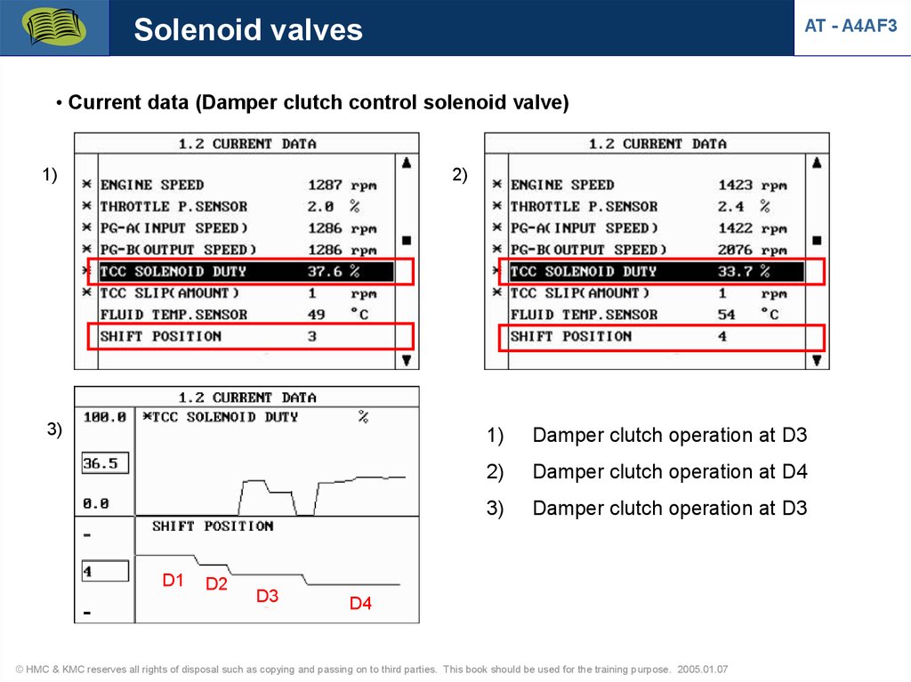
Solenoid valvesAT - A4AF3
• Current data (Damper clutch control solenoid valve)
1)
2)
3)
D1
D2
D3
1)
Damper clutch operation at D3
2)
Damper clutch operation at D4
3)
Damper clutch operation at D3
D4
© HMC & KMC reserves all rights of disposal such as copying and passing on to third parties. This book should be used for the training purpose. 2005.01.07
53.
Solenoid valvesAT - A4AF3
• Current data (Pressure control solenoid valve)
1)
2)
D1
N-D
N-D
D1
1)
PCSV-A, PCSV-B operation at D1
2)
PCSV-A, PCSV-B operation at N-D
3)
D1
D2
3)
D3
D4
PCSV-A, PCSV-B operation at D range
D123
© HMC & KMC reserves all rights of disposal such as copying and passing on to third parties. This book should be used for the training purpose. 2005.01.07
D4
54.
Solenoid valvesAT - A4AF3
• Current data (Shift control solenoid valve)
1)
2)
ON (D1)
ON (D4)
ON (D12)
OFF (D23)
OFF (D34)
3rd gear
3)
4th gear
OFF (D12)
3rd 4th
1)
SCSV-A, operation at D range
2)
SCSV-B, operation at D range
3)
SCSV-C, operation at D range
ON (D34)
© HMC & KMC reserves all rights of disposal such as copying and passing on to third parties. This book should be used for the training purpose. 2005.01.07
55.
Solenoid valvesAT - A4AF3
• Circuit diagram
[DCCSV duty signal]
[PCSV-A duty signal-duty 100%]
© HMC & KMC reserves all rights of disposal such as copying and passing on to third parties. This book should be used for the training purpose. 2005.01.07
56.
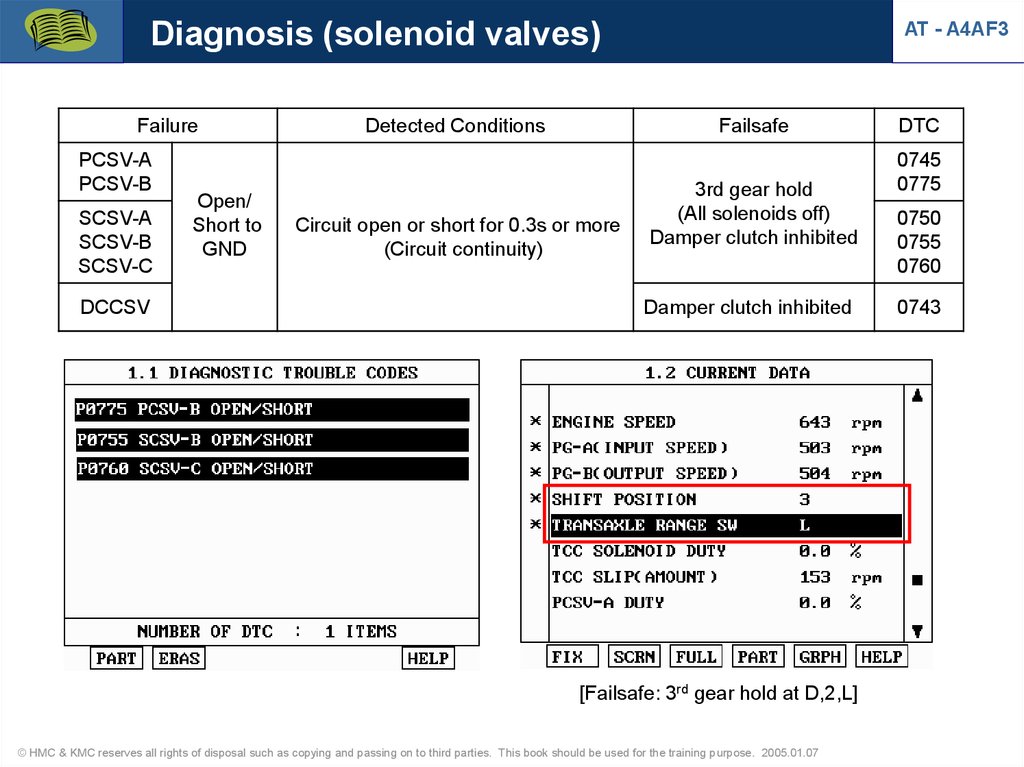
Diagnosis (solenoid valves)Failure
PCSV-A
PCSV-B
SCSV-A
SCSV-B
SCSV-C
DCCSV
Open/
Short to
GND
Detected Conditions
AT - A4AF3
Failsafe
Circuit open or short for 0.3s or more
(Circuit continuity)
3rd gear hold
(All solenoids off)
Damper clutch inhibited
Damper clutch inhibited
[Failsafe: 3rd gear hold at D,2,L]
© HMC & KMC reserves all rights of disposal such as copying and passing on to third parties. This book should be used for the training purpose. 2005.01.07
DTC
0745
0775
0750
0755
0760
0743
57.
Diagnosis (damper clutch control)AT - A4AF3
* Rationality(Closed stuck)
Component
System
Fault Code
Description
Malfunction
Criteria
Threshold
Damper clutch
system
P0742
Closed stuck
Calculated slip
Slip < 5[rpm]
Filtering
MIL On
Time
3[sec]
2drv.
cycle
* Slip = Engine speed - Input speed
Test Condition
Fail safety
Solenoid 3(DCSV) no error
No dynamic state
Last changed time of shift type > 3[sec]
Position lever, Input speed sensor, OTS, Output speed sensor, Engine speed
sensor
no error
Engine speed > 0[rpm]
Duty of DCSV = 0[%]
Throttle opening > 20[%]
Output speed > 1000[rpm]
Inhibitor switch = D, 2, L
-10[ºC] < Oil temperature < 130[ºC]
Damper open
© HMC & KMC reserves all rights of disposal such as copying and passing on to third parties. This book should be used for the training purpose. 2005.01.07
58.
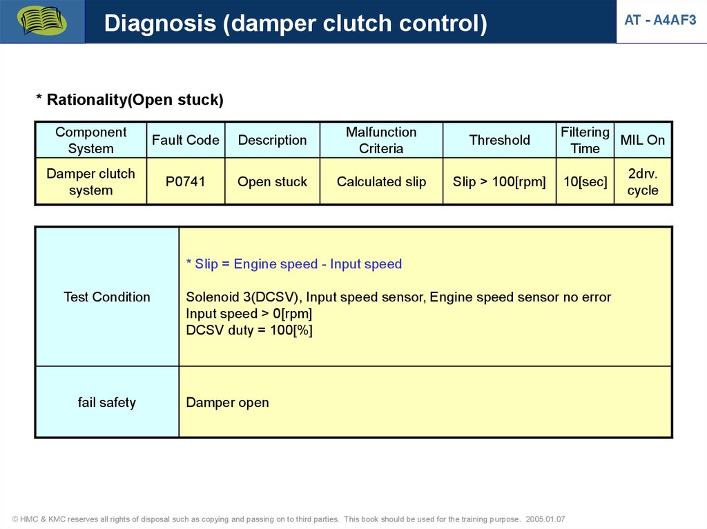
Diagnosis (damper clutch control)AT - A4AF3
* Rationality(Open stuck)
Component
System
Fault Code
Description
Malfunction
Criteria
Threshold
Damper clutch
system
P0741
Open stuck
Calculated slip
Slip > 100[rpm]
Filtering
MIL On
Time
10[sec]
* Slip = Engine speed - Input speed
Test Condition
fail safety
Solenoid 3(DCSV), Input speed sensor, Engine speed sensor no error
Input speed > 0[rpm]
DCSV duty = 100[%]
Damper open
© HMC & KMC reserves all rights of disposal such as copying and passing on to third parties. This book should be used for the training purpose. 2005.01.07
2drv.
cycle
59.
Diagnosis (CAN BUS OFF Error)AT - A4AF3
* CAN BUS OFF
Component
System
Fault Code
Description
Malfunction
Criteria
Threshold
CAN bus
U0001
Network error
Status of CAN Bus
Status of
CAN Bus=1
Test Condition
Fail safety
Filtering
MIL On
Time
1[sec]
Battery voltage > 10[V]
Input speed > 300[rpm]
Ignition On
Input speed no error
Filtering time > 0.5[sec]
1. If external CAN is Bus off, TCM is switching to internal CAN with ECM.
2. If external and internal CAN is all error, refer to below.
- Engine RPM = 3000 RPM
- Indicated Engine Torque = 80%
- Vehicle speed = 0 km/h, A/C SW = Off
- Engine Temp = 70'C, Throttle angle = 50%
- Lamp "Check engine for OBD" = Off
- Shift prevention from TCS = Off
© HMC & KMC reserves all rights of disposal such as copying and passing on to third parties. This book should be used for the training purpose. 2005.01.07
2drv.
cycle
60.
Diagnosis (CAN BUS OFF Error)• CAN BUS OFF Error dection
1) CAN-Low short to GND : DTC is not detected
CAN communication with Scan tool is normal
Current data from engine is normal
2) CAN-Low short to B+ : Communication error with Hi-scan
DTC (U0001) is memorized
3) CAN-High short to GND or B+ : Communication error with Hi-scan
DTC (U0001) is memorized
• CAN interface required system (for Hi-scan communication)
: Engine, AT, Immobilizer, Code saving
• K-line communication system (without CAN interface)
: ABS, ESP, A/Bag, TPMS
© HMC & KMC reserves all rights of disposal such as copying and passing on to third parties. This book should be used for the training purpose. 2005.01.07
AT - A4AF3
61.
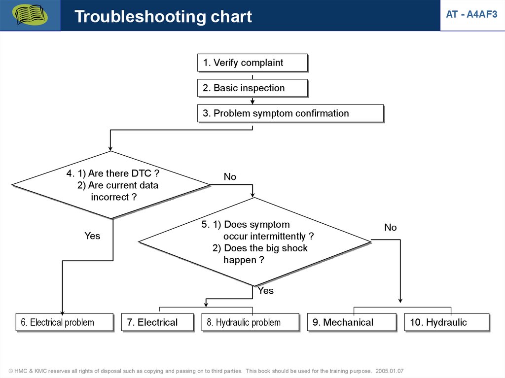
Troubleshooting chartAT - A4AF3
1. Verify complaint
2. Basic inspection
3. Problem symptom confirmation
4. 1) Are there DTC ?
2) Are current data
incorrect ?
No
5. 1) Does symptom
occur intermittently ?
2) Does the big shock
happen ?
Yes
No
Yes
6. Electrical problem
7. Electrical
8. Hydraulic problem
9. Mechanical
© HMC & KMC reserves all rights of disposal such as copying and passing on to third parties. This book should be used for the training purpose. 2005.01.07
10. Hydraulic
62.
Troubleshooting chartAT - A4AF3
6. Electrical problem
7. Electrical
8. Hydraulic problem
9. Mechanical
10. Hydraulic
DTC chart, circuit &
input sensor
inspection
Actuator test
Oil passage or
valve body clean
and check
Stall test
Hydraulic test
Driving test
for flight
record
11. Identification of problem
12. Repair
13. Confirmation test
14. END
© HMC & KMC reserves all rights of disposal such as copying and passing on to third parties. This book should be used for the training purpose. 2005.01.07
63.
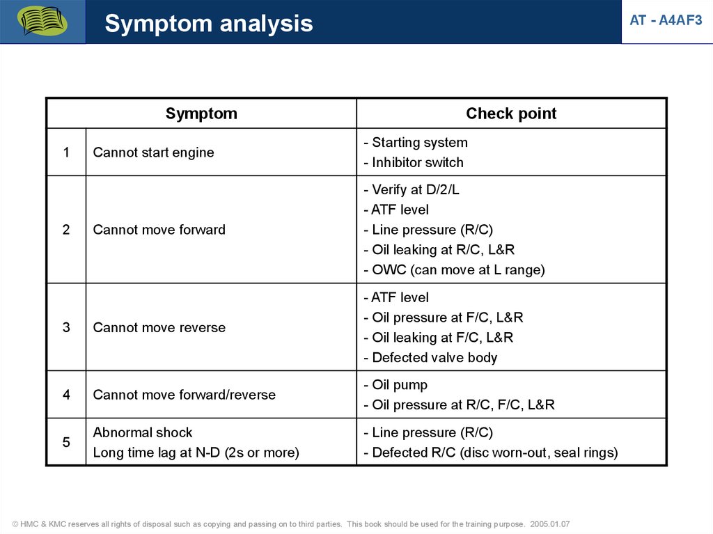
Symptom analysisSymptom
AT - A4AF3
Check point
Cannot start engine
- Starting system
- Inhibitor switch
Cannot move forward
- Verify at D/2/L
- ATF level
- Line pressure (R/C)
- Oil leaking at R/C, L&R
- OWC (can move at L range)
3
Cannot move reverse
- ATF level
- Oil pressure at F/C, L&R
- Oil leaking at F/C, L&R
- Defected valve body
4
Cannot move forward/reverse
- Oil pump
- Oil pressure at R/C, F/C, L&R
5
Abnormal shock
Long time lag at N-D (2s or more)
- Line pressure (R/C)
- Defected R/C (disc worn-out, seal rings)
1
2
© HMC & KMC reserves all rights of disposal such as copying and passing on to third parties. This book should be used for the training purpose. 2005.01.07
64.
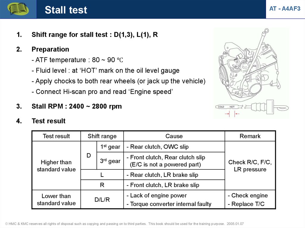
Stall testAT - A4AF3
1.
Shift range for stall test : D(1,3), L(1), R
2.
Preparation
- ATF temperature : 80 ~ 90 ℃
- Fluid level : at ‘HOT’ mark on the oil level gauge
- Apply chocks to both rear wheels (or jack up the vehicle)
- Connect Hi-scan pro and read ‘Engine speed’
3.
Stall RPM : 2400 ~ 2800 rpm
4.
Test result
Test result
Shift range
D
Higher than
standard value
Lower than
standard value
Cause
1st gear
- Rear clutch, OWC slip
3rd gear
- Front clutch, Rear clutch slip
(E/C is not a powered part)
L
- Rear clutch, LR brake slip
R
- Front clutch, LR brake slip
D/L/R
- Lack of engine power
- Torque converter internal faulty
Remark
Check R/C, F/C,
LR pressure
- Check engine
- Replace T/C
© HMC & KMC reserves all rights of disposal such as copying and passing on to third parties. This book should be used for the training purpose. 2005.01.07
65.
Pressure test1.
Pressure test range : D/2/L/R
2.
Preparation
AT - A4AF3
- Warm up the engine and ATF temperature : 80 ~ 90 ℃
- Fluid level : at ‘HOT’ mark on the oil level gauge
- Jack up the vehicle
- Install oil pressure gauge (09452-21500) and gauge adapter (09452-21001,2)
on each pressure port
- Read pressure value at idling or stall rpm
3.
Standard value : Refer to workshop manual
Required SST
09452-21002
09452-2150
09452-21001
© HMC & KMC reserves all rights of disposal such as copying and passing on to third parties. This book should be used for the training purpose. 2005.01.07
66.
Pressure test4.
1.
2.
3.
4.
AT - A4AF3
Pressure ports
Reducing pressure
Kickdown wervo pressure
Rear clutch pressure
Front clutch pressure
5.
6.
7.
8.
End clutch pressure
Low & reverse brake pressure
Damper clutch apply pressure
Damper clutch release pressure
© HMC & KMC reserves all rights of disposal such as copying and passing on to third parties. This book should be used for the training purpose. 2005.01.07
67.
Pressure test5.
AT - A4AF3
Diagnosis of test result
Result
Cause
- Front clutch piston leaking (D-rings)
- Defected front clutch retainer bushing
Poor front clutch pressure
- Defected housing oil seal rings
- Defected kickdown servo piston seal ring
- Defected valve body
Poor end clutch pressure
- End clutch piston leaking (oil seal, D-ring)
- Defected valve body
- Poor O-ring between upper valve body and AT housing
Poor L&R brake pressure
- L&R brake piston leaking (O-ring)
- Defected valve body
- DCCSV sticking
Poor damper clutch pressure
- Oil cooler clogging or leaking
- Defected input shaft seal rings
- Torque converter internal faulty
© HMC & KMC reserves all rights of disposal such as copying and passing on to third parties. This book should be used for the training purpose. 2005.01.07
68.
Pressure test (Preparation)AT Tester with adapter cables for AT (F4A**, F4EL-K, AISIN)
© HMC & KMC reserves all rights of disposal such as copying and passing on to third parties. This book should be used for the training purpose. 2005.01.07
AT - A4AF3
69.
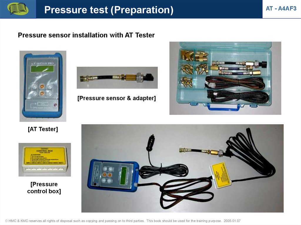
Pressure test (Preparation)Pressure sensor installation with AT Tester
[Pressure sensor & adapter]
[AT Tester]
[Pressure
control box]
© HMC & KMC reserves all rights of disposal such as copying and passing on to third parties. This book should be used for the training purpose. 2005.01.07
AT - A4AF3
70.
Pressure test (Preparation)Pressure sensor installation with AT Tester
© HMC & KMC reserves all rights of disposal such as copying and passing on to third parties. This book should be used for the training purpose. 2005.01.07
AT - A4AF3
71.
Pressure testAT - A4AF3
1) Rear clutch pressure
N D
D N
Duty
controlled
N D
D N
ON
OFF
2.7V = 8.2kg/cm2
Rear clutch pressure
[R/C pressure & PCSV-B operation at N D N]
[R/C pressure & SCSV-A operation at N D N]
© HMC & KMC reserves all rights of disposal such as copying and passing on to third parties. This book should be used for the training purpose. 2005.01.07
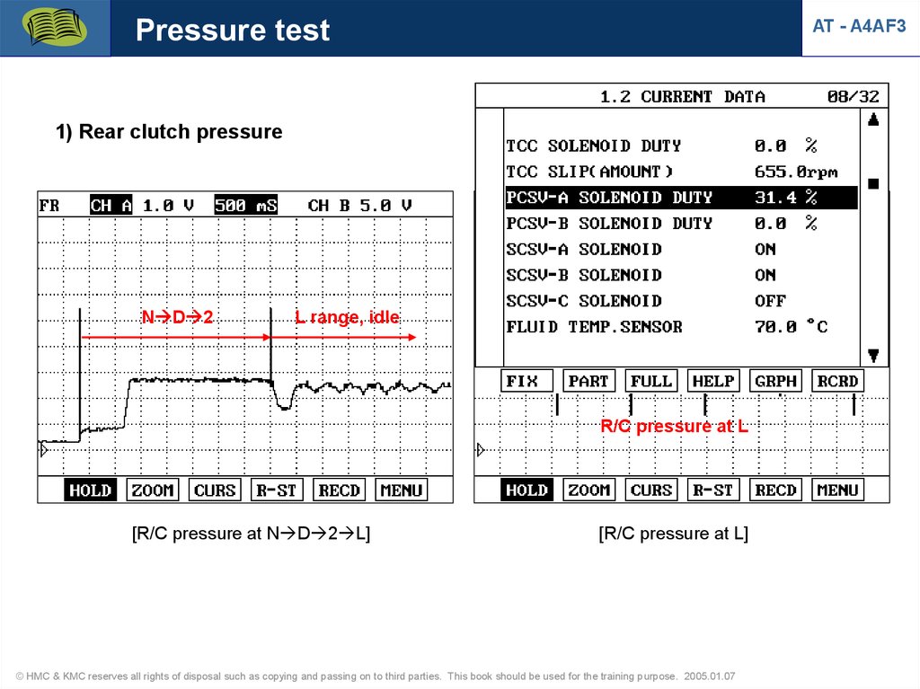
72.
Pressure testAT - A4AF3
1) Rear clutch pressure
PCSV-A duty control
N D 2
L range, idle
R/C pressure at L
[R/C pressure at N D 2 L]
[R/C pressure at L]
© HMC & KMC reserves all rights of disposal such as copying and passing on to third parties. This book should be used for the training purpose. 2005.01.07
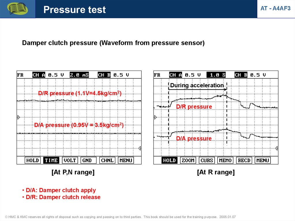
73.
Pressure testAT - A4AF3
Damper clutch pressure (Waveform from pressure sensor)
During acceleration
D/R pressure (1.1V=4.5kg/cm2)
D/R pressure
D/A pressure (0.95V = 3.5kg/cm2)
D/A pressure
[At P,N range]
[At R range]
• D/A: Damper clutch apply
• D/R: Damper clutch release
© HMC & KMC reserves all rights of disposal such as copying and passing on to third parties. This book should be used for the training purpose. 2005.01.07
74.
Pressure testAT - A4AF3
Damper clutch pressure (Waveform from pressure sensor)
a
b
c
d
a
b c
d
D/R pressure
D/A pressure
2~3.5 kg/cm2
[At D range]
* a : D 1,2,3 gear
b: D 3 gear with damper clutch engaged (lock-up)
c: D3-4 up shift (no lock-up)
d: D4 gear with lock-up
© HMC & KMC reserves all rights of disposal such as copying and passing on to third parties. This book should be used for the training purpose. 2005.01.07
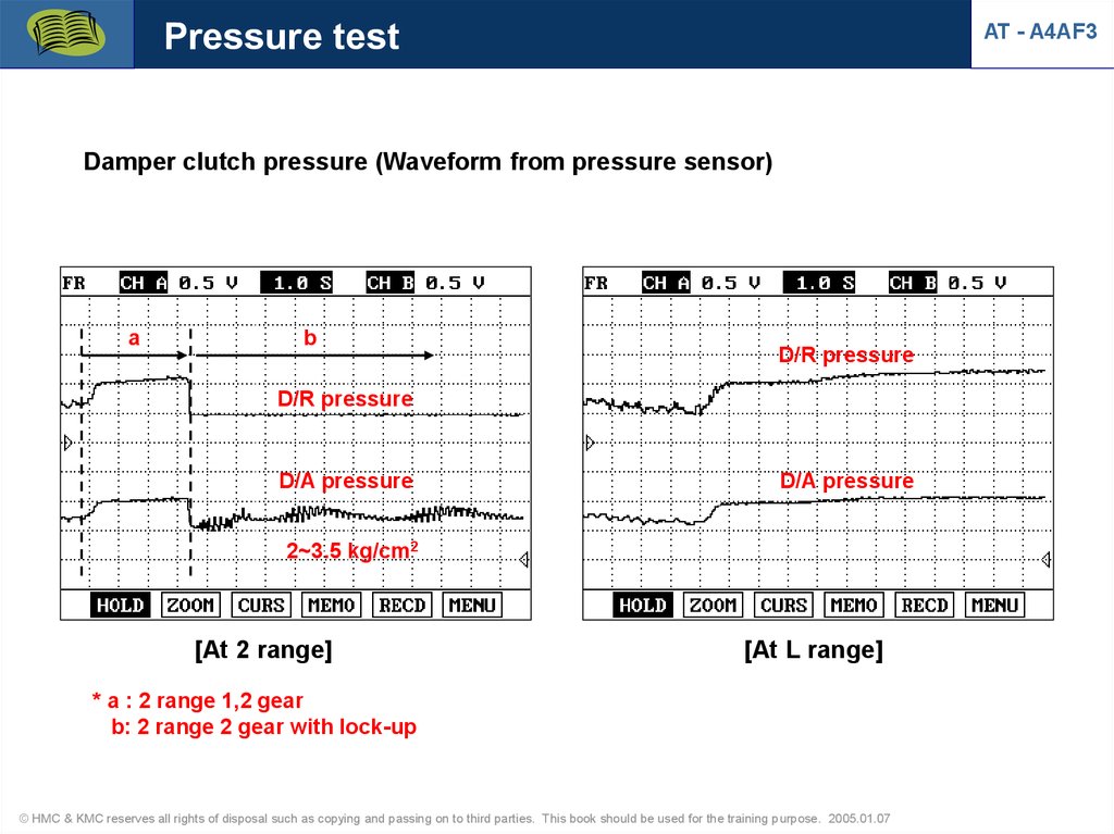
75.
Pressure testAT - A4AF3
Damper clutch pressure (Waveform from pressure sensor)
a
b
D/R pressure
D/R pressure
D/A pressure
D/A pressure
2~3.5 kg/cm2
[At 2 range]
[At L range]
* a : 2 range 1,2 gear
b: 2 range 2 gear with lock-up
© HMC & KMC reserves all rights of disposal such as copying and passing on to third parties. This book should be used for the training purpose. 2005.01.07
76.
Pressure testAT - A4AF3
Kick down servo apply pressure (Waveform from pressure sensor)
N range
D range
D1
D2
D3
D4
7 kg/cm2
Servo apply pressure
6.5
8.5 kg/cm2
kg/cm2
D1(ON)
D23(OFF)
D4(ON)
SCSV-A
[At N-D control]
[At D range]
© HMC & KMC reserves all rights of disposal such as copying and passing on to third parties. This book should be used for the training purpose. 2005.01.07
77.
Pressure testAT - A4AF3
Kick down servo apply pressure (Waveform from pressure sensor)
2-2 (Servo apply pressure)
8.5 kg/cm2
SCSV-A
2-1(ON)
2-2(OFF)
[At 2 range]
© HMC & KMC reserves all rights of disposal such as copying and passing on to third parties. This book should be used for the training purpose. 2005.01.07
78.
Pressure testAT - A4AF3
L&R brake pressure (Waveform from pressure sensor)
N R
2 L
Acceleration
Acceleration
17 kg/cm2
12 kg/cm2
4~6 kg/cm2
a
b
PCSV-A duty control (32%)
[At R range]
[At L range]
a: PCSV-A duty control
b: PCSV-A duty 0% (accleration)
© HMC & KMC reserves all rights of disposal such as copying and passing on to third parties. This book should be used for the training purpose. 2005.01.07
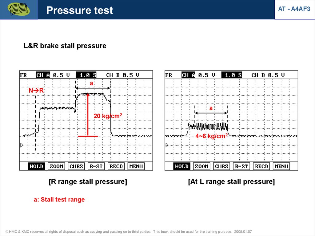
79.
Pressure testAT - A4AF3
L&R brake stall pressure
a
N R
a
20 kg/cm2
4~6 kg/cm2
[R range stall pressure]
[At L range stall pressure]
a: Stall test range
© HMC & KMC reserves all rights of disposal such as copying and passing on to third parties. This book should be used for the training purpose. 2005.01.07