 Construction
Similar presentations:


")

Α new seismic energy absorption device through simultaneously yield and friction used for the protection of structures
1.
Α NEW SEISMIC ENERGY ABSORPTION DEVICE THROUGHSIMULTANEOUSLY YIELD AND FRICTION USED FOR THE
PROTECTION OF STRUCTURES
Panikos PAPADOPOULOS 1, Magdalini TITIRLA 2, Alkis PAPADOPOULOS3
ABSTRACT
Passive energy dissipation systems do not require external power to generate system control forces and
hence, are easy and cheap to implement in a structure (existing or new). The new seismic energy
absorption device, which is presented in this paper, is an improvement of the device CAR, proposed
by Papadopoulos et al (2008) and it is incorporated at the ends of the steel diagonal bars. The
improved device, through replaced the traverse elastoplastic regulation bolts with superimposed steel
blades, aims at avoiding material fatigues of the bolt because of the repeated load cycles. Also it has
many advantages. First of all, it limits the maximum axial forces developed in the steel diagonal bars
of the structure, with the appropriate choice of dimensions and characteristics of the superimposed
steel blades. Also, allows additional horizontal relative floor displacements of the structure without
increasing the axial load of the steel diagonal bars, which means increase of the absorbed seismic
energy. The main advantage of the proposed new device is that it can function reliably under large
cycles of dynamic load, where large horizontal relative floor displacements develop. At the same time,
when the horizontal relative floor displacement reaches a characteristic value, then the new device
locks, so that the buckling of the compressed diagonal bars is decisively removed, so introduces
second degree of protection of the structure in the case of very strong earthquakes. So this
improvement is capable of producing higher axial forces and deformations, before the collapse. In
order to investigate the suitability of the new proposed device CAR1 described in the present paper,
nonlinear analyses have been carried out using, on one hand, a static pushover procedure with lateral
floor monotonic incremental static forces with a triangular distribution in elevation and, on the other
hand, nonlinear response history analysis with suitable seismic artificial accelerograms. Two different
structures of reinforced concrete are used, of which the first is a one storey planar structure with five
frames and the second is a three storey planar structure. Also each structure is being analyzed using
the pushover analysis and time history analysis, as regards three different cases, the initial pure r/c
frame without strengthening, the simple strengthening frame and the strengthening frame with the new
proposed device CAR1.
INTRODUCTION
The safety of construction (existing or new) is one of the major priorities of engineering globally,
because structures often subject to large and often devastating, for their viability, loadings. The law of
conservation of energy imposes the restriction that the energy must either be absorbed and/or
dissipated by the structure. Most structures have an inherent damping in them which results in some of
1
Assist. Professor, Aristotle University of Thessaloniki, Greece, paniko@civil.auth.gr
Civil Eng., MSc, PhD candidate, Aristotle University of Thessaloniki, Greece, mtitirla@civil.auth.gr
3
Civil Eng., PhD candidate, Aristotle University of Thessaloniki, Greece, alkisp25@gmail.com
2
1
2.
this energy being dissipated, but a large amount of energy is absorbed by the structure, undergoingseveral deformations and maybe even collapse. So, great interest is in the study of the innovations of
the design and materials of construction that minimize the probability of failure of the structure in any
charging. Therefore, many efforts have been made to create devices that will absorb the majority of
the seismic energy but will not belong to the supporting structure of the construction. The main
advantages of these, is the easy replacement or repair. These devices belong to the passive energy
dissipation systems, do not require external power to generate system control forces and hence, are
easy and cheap to implement in a structure.
Passive energy dissipation devices such as visco-elastic dampers, metallic dampers and friction
dampers have widely been used to reduce the dynamic response of civil engineering structures
subjected to seismic loads. Their effectiveness for seismic design of building structures is attributed to
minimizing structural damages by absorbing the structural vibratory energy and by dissipating it
through their inherent hysteresis behavior (Soong et al. 1997).
Among these dampers, friction dampers with various designs have been developed and applied
for the seismic protection of building structures since their hysteretic behaviors could be kept stable
for cyclic loads and desirable slip loads are easily abtained by regulating normal forces acting
perpendicularly to a friction surface, in addition to their simple energy dissipation mechanism and
easy manufacturing, installation and maintenance (Pall and Marsh, 1982; Fitzgerald et al., 1989;
Constantinou et al. 1990; Grigorian et al 1993, Papadopoulos 2012).
THE PROPOSED DEVICE
Α new seismic energy absorption device is presented in this paper. The device is an improvement of
the device CAR proposed by Papadopoulos et al (2008). Both devices have the advantage to (i)
provide additional stiffness as well as (ii) absorption of seismic energy, (iii) provision of control of the
axial forces that are developed at the diagonal steel rods and last but not least the ability to retain the
plastic displacements to a desired level.
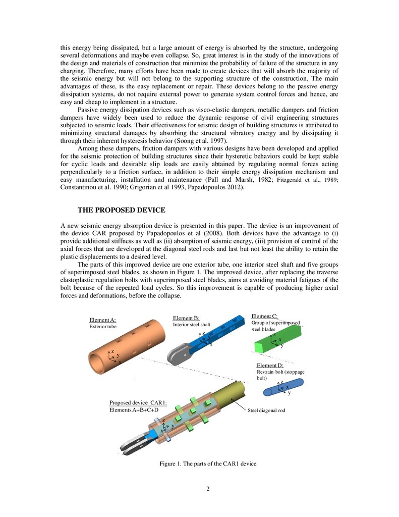
The parts of this improved device are one exterior tube, one interior steel shaft and five groups
of superimposed steel blades, as shown in Figure 1. The improved device, after replacing the traverse
elastoplastic regulation bolts with superimposed steel blades, aims at avoiding material fatigues of the
bolt because of the repeated load cycles. So this improvement is capable of producing higher axial
forces and deformations, before the collapse.
Element C:
Element Β:
Element Α:
Interior steel shaft
Exterior tube
z
z
Group of superimposed
steel blades
z
y
x
y
x
x
y
Element D:
Restrain bolt (stoppage
bolt)
z
Proposed device CAR1:
Elements Α+Β+C+D
Steel diagonal rod
z
x
y
Figure 1. The parts of the CAR1 device
2
x
y
3.
3P. Papadopoulos, M. Titirla, A. Papadopoulos
The relevant movement of elements A and B is carried out by an elastoplastic bending
deformation of the superimposed steel blades that connect crosswise elements A and B. The number
and the dimensions of superimposed steel blades as well as their elastoplastic characteristics define the
principle of elastoplastic behaviour of the diagonal bars on an axial load. There is also a provision for
a Restrain bolt (stoppage bolt). This bolt is made of high yield Steel, and can slide inactively through
an appropriately selected oval hole at element A. As a result, the activation of this bolt is carried out at
a “second time” and it allows the desired plastic deformations of the superimposed steel blades to take
place. The activation of the stoppage bolt allows the transfer of an additional axial load from elements
A to element B of the device. An appropriate configuration / geometry in the area of the stoppage bolt
(oval hole) eliminates any additional compression forces on the diagonal elements and allows only
tensional forces to be developed.
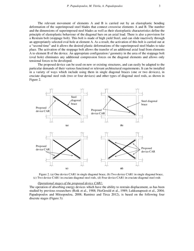
The proposed device can be used on new or existing structures, and can easily be adapted to the
particular demands of their various functional or relevant architectural requirements. It can be installed
in a variety of ways which include using them in single diagonal braces (one or two devices), in
cruciate diagonal steel rods (two or four devices) and other types of diagonal steel rods, as shown in
Figure 2.
Steel
diagonal
brace
Proposed
device CAR
Steel diagonal
brace
Proposed
device CAR
(a)
(b)
Proposed
device CAR
Proposed
device CAR
(c)
(d)
Figure 2. (a) One device CAR1 in single diagonal brace, (b) Two device CAR1 in single diagonal brace,
(c) Two device CAR1 in cruciate diagonal steel rods, (d) Four device CAR1 in cruciate diagonal steel rods
Operational stages of the proposed device CAR1:
The operation of absorbing energy devices which have the ability to restrain displacement, as has been
studied by previous researchers (Roik et al., 1988; FitzGerald et al., 1989; Lukkunaprasit et al., 2004;
Papadopoulos and Mitsopoulou, 2008; Ramirez and Tirca 2012), is based on the following four
discrete stages (Figure 3):
4.
DAxial Force of diagonal rods (kN)
Fmax
Fs
B
E
Tensile member
C
Relative floor displacement (m)
A
uy
umax
B
E
-Fs
Compressive member
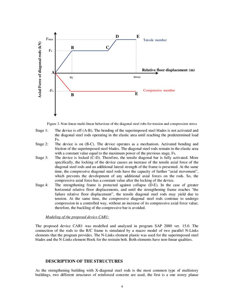
Figure 3. Non-linear multi-linear behaviour of the diagonal steel robs for tension and compression stress
Stage 1:
Stage 2:
Stage 3:
Stage 4:
The device is off (A-B). The bending of the superimposed steel blades is not activated and
the diagonal steel rods operating in the elastic area until reaching the predetermined load
Fs.
The device is on (B-C). The device operates as a mechanism. Activated bending and
friction of the superimposed steel blades. The diagonal steel rods remain in the elastic area
with a constant value equal to the maximum power of the previous stage, Fs.
The device is locked (C-D). Therefore, the tensile diagonal bar is fully activated. More
specifically, the locking of the device causes an increase of the tensile axial force of the
diagonal steel rods and an additional lateral strength of the frame is presented. At the same
time, the compressive diagonal steel rods have the capacity of further “axial movement”,
which prevents the development of any additional axial forces on the rods. So, the
compressive axial force has a constant value after the locking of the device.
The strengthening frame is protected against collapse (D-E). In the case of greater
horizontal relative floor displacements, and until the strengthening frame reaches “the
failure relative floor displacement”, the tensile diagonal steel rods may yield due to
tension. At the same time, the compressive diagonal steel rods continue to undergo
compression in a controlled way, without an increase of its compressive axial force value;
therefore, the buckling of the compressive bar is avoided.
Modeling of the proposed device CAR1:
The proposed device CAR1 was modelled and analyzed in program SAP 2000 ver. 15.0. The
connection of the rods to the R/C frame is simulated by a macro model of two parallel N-Links
elements that the program provides. The N-Links element plastic was used for the superimposed steel
blades and the N-Links element Hook for the restrain bolt. Both elements have non-linear qualities.
DESCRIPTION OF THE STRUCTURES
As the strengthening building with X-diagonal steel rods is the most common type of multistory
buildings, two different structures of reinforced concrete are used, the first is a one storey planar
4
5.
5P. Papadopoulos, M. Titirla, A. Papadopoulos
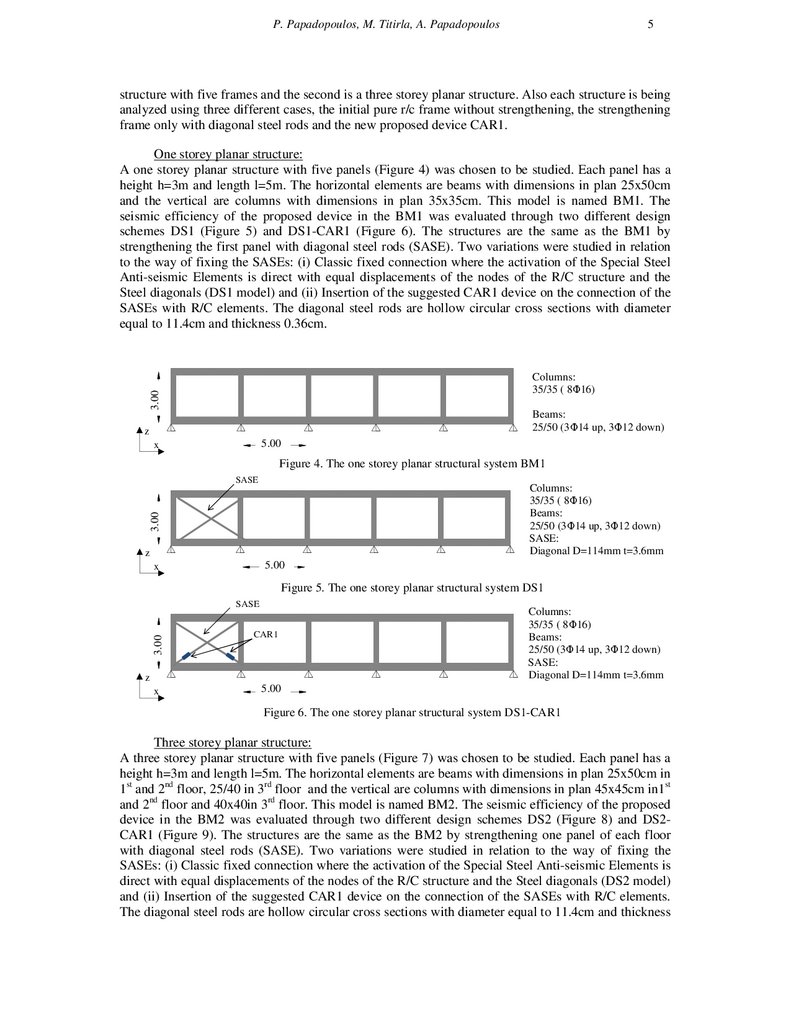
structure with five frames and the second is a three storey planar structure. Also each structure is being
analyzed using three different cases, the initial pure r/c frame without strengthening, the strengthening
frame only with diagonal steel rods and the new proposed device CAR1.
One storey planar structure:
A one storey planar structure with five panels (Figure 4) was chosen to be studied. Each panel has a
height h=3m and length l=5m. The horizontal elements are beams with dimensions in plan 25x50cm
and the vertical are columns with dimensions in plan 35x35cm. This model is named BM1. The
seismic efficiency of the proposed device in the BM1 was evaluated through two different design
schemes DS1 (Figure 5) and DS1-CAR1 (Figure 6). The structures are the same as the BM1 by
strengthening the first panel with diagonal steel rods (SASE). Two variations were studied in relation
to the way of fixing the SASEs: (i) Classic fixed connection where the activation of the Special Steel
Anti-seismic Elements is direct with equal displacements of the nodes of the R/C structure and the
Steel diagonals (DS1 model) and (ii) Insertion of the suggested CAR1 device on the connection of the
SASEs with R/C elements. The diagonal steel rods are hollow circular cross sections with diameter
equal to 11.4cm and thickness 0.36cm.
5.00
3.00
Columns:
35/35 ( 8Φ16)
Beams:
25/50 (3Φ14 up, 3Φ12 down)
z
7.00
5.00
x
Figure 4. The one storey planar structural system BM1
5.00
3.00
SASE
z
7.00
5.00
x
Columns:
35/35 ( 8Φ16)
Beams:
25/50 (3Φ14 up, 3Φ12 down)
SASE:
Diagonal D=114mm t=3.6mm
Figure 5. The one storey planar structural system DS1
5.00
3.00
SASE
z
x
CAR1
Columns:
35/35 ( 8Φ16)
Beams:
25/50 (3Φ14 up, 3Φ12 down)
SASE:
Diagonal D=114mm t=3.6mm
7.00
5.00
Figure 6. The one storey planar structural system DS1-CAR1
Three storey planar structure:
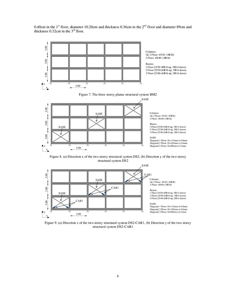
A three storey planar structure with five panels (Figure 7) was chosen to be studied. Each panel has a
height h=3m and length l=5m. The horizontal elements are beams with dimensions in plan 25x50cm in
1st and 2nd floor, 25/40 in 3rd floor and the vertical are columns with dimensions in plan 45x45cm in1st
and 2nd floor and 40x40in 3rd floor. This model is named BM2. The seismic efficiency of the proposed
device in the BM2 was evaluated through two different design schemes DS2 (Figure 8) and DS2CAR1 (Figure 9). The structures are the same as the BM2 by strengthening one panel of each floor
with diagonal steel rods (SASE). Two variations were studied in relation to the way of fixing the
SASEs: (i) Classic fixed connection where the activation of the Special Steel Anti-seismic Elements is
direct with equal displacements of the nodes of the R/C structure and the Steel diagonals (DS2 model)
and (ii) Insertion of the suggested CAR1 device on the connection of the SASEs with R/C elements.
The diagonal steel rods are hollow circular cross sections with diameter equal to 11.4cm and thickness
6.
3.000.40cm in the 1st floor, diameter 10.20cm and thickness 0.36cm in the 2nd floor and diameter 89cm and
thickness 0.32cm in the 3rd floor.
3.00
Columns:
1& 2 Floor: 45/45 ( 8Φ20)
3 Floor: 40/40 ( 8Φ16)
3.00
Beams:
1 Floor:25/50 (8Φ16 up, 3Φ14 down)
2 Floor:25/50 (6Φ18 up, 3Φ14 down)
3 Floor:25/40 (6Φ16 up, 2Φ14 down)
z
5.00
x
Figure 7. The three storey planar structural system BM2
3.00
SASE
Columns:
1& 2 Floor: 45/45 ( 8Φ20)
3 Floor: 40/40 ( 8Φ16)
3.00
SASE
Beams:
1 Floor:25/50 (8Φ16 up, 3Φ14 down)
2 Floor:25/50 (6Φ18 up, 3Φ14 down)
3 Floor:25/40 (6Φ16 up, 2Φ14 down)
3.00
SASE
z
SASE:
Diagonal 1 Floor: D=114mm t=4.0mm
Diagonal 2 Floor: D=102mm t=3.6mm
Diagonal 2 Floor: D=89mm t=3.2mm
5.00
x
Figure 8. (a) Direction x of the two storey structural system DS2, (b) Direction y of the two storey
structural system DS2
3.00
SASE
CAR1
Columns:
1& 2 Floor: 45/45 ( 8Φ20)
3 Floor: 40/40 ( 8Φ16)
SASE
3.00
CAR1
3.00
SASE
z
x
Beams:
1 Floor:25/50 (8Φ16 up, 3Φ14 down)
2 Floor:25/50 (6Φ18 up, 3Φ14 down)
3 Floor:25/40 (6Φ16 up, 2Φ14 down)
CAR1
SASE:
Diagonal 1 Floor: D=114mm t=4.0mm
Diagonal 2 Floor: D=102mm t=3.6mm
Diagonal 2 Floor: D=89mm t=3.2mm
5.00
Figure 9. (a) Direction x of the two storey structural system DS2-CAR1, (b) Direction y of the two storey
structural system DS2-CAR1
6
7.
7P. Papadopoulos, M. Titirla, A. Papadopoulos
RESULTS OF ANALYSES
One storey planar structure:
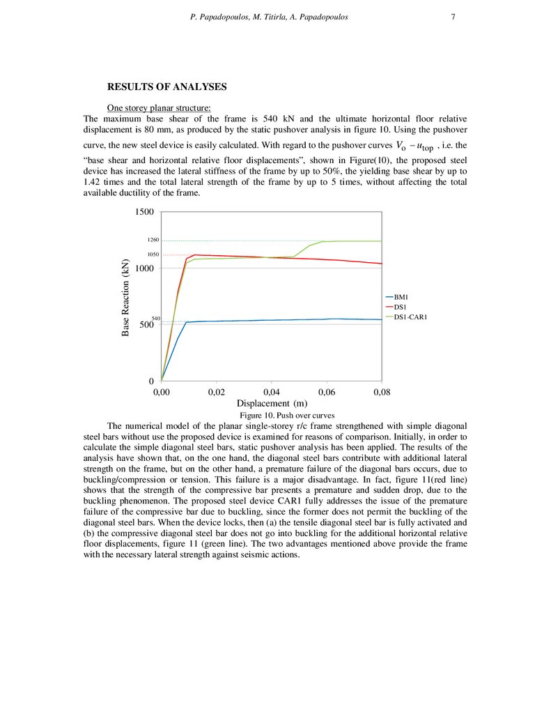
The maximum base shear of the frame is 540 kN and the ultimate horizontal floor relative
displacement is 80 mm, as produced by the static pushover analysis in figure 10. Using the pushover
curve, the new steel device is easily calculated. With regard to the pushover curves Vo − utop , i.e. the
“base shear and horizontal relative floor displacements”, shown in Figure(10), the proposed steel
device has increased the lateral stiffness of the frame by up to 50%, the yielding base shear by up to
1.42 times and the total lateral strength of the frame by up to 5 times, without affecting the total
available ductility of the frame.
1500
1260
Base Reaction (kN)
1050
1000
BM1
DS1
DS1-CAR1
540
500
0
0,00
0,02
0,04
0,06
0,08
Displacement (m)
Figure 10. Push over curves
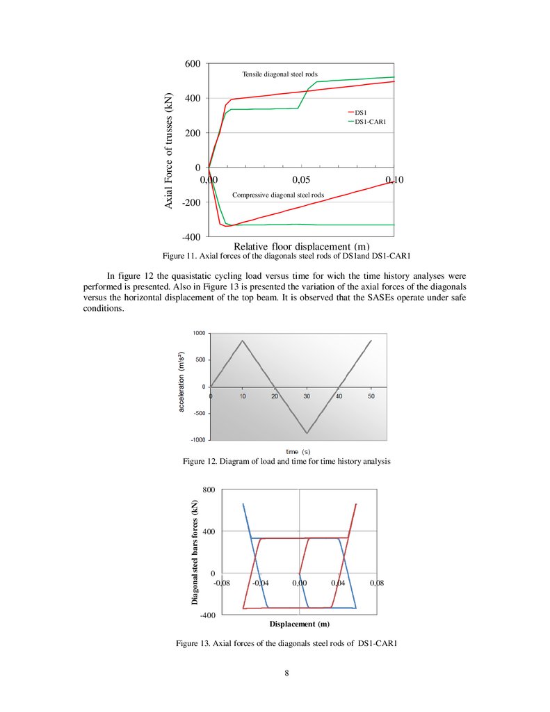
The numerical model of the planar single-storey r/c frame strengthened with simple diagonal
steel bars without use the proposed device is examined for reasons of comparison. Initially, in order to
calculate the simple diagonal steel bars, static pushover analysis has been applied. The results of the
analysis have shown that, on the one hand, the diagonal steel bars contribute with additional lateral
strength on the frame, but on the other hand, a premature failure of the diagonal bars occurs, due to
buckling/compression or tension. This failure is a major disadvantage. In fact, figure 11(red line)
shows that the strength of the compressive bar presents a premature and sudden drop, due to the
buckling phenomenon. The proposed steel device CAR1 fully addresses the issue of the premature
failure of the compressive bar due to buckling, since the former does not permit the buckling of the
diagonal steel bars. When the device locks, then (a) the tensile diagonal steel bar is fully activated and
(b) the compressive diagonal steel bar does not go into buckling for the additional horizontal relative
floor displacements, figure 11 (green line). The two advantages mentioned above provide the frame
with the necessary lateral strength against seismic actions.
8.
600Axial Force of trusses (kN)
Tensile diagonal steel rods
400
DS1
DS1-CAR1
200
0
0,00
0,05
0,10
Compressive diagonal steel rods
-200
-400
Relative floor displacement (m)
Figure 11. Axial forces of the diagonals steel rods of DS1and DS1-CAR1
In figure 12 the quasistatic cycling load versus time for wich the time history analyses were
performed is presented. Also in Figure 13 is presented the variation of the axial forces of the diagonals
versus the horizontal displacement of the top beam. It is observed that the SASEs operate under safe
conditions.
Figure 12. Diagram of load and time for time history analysis
Diagonal steel bars forces (kN)
800
400
0
-0,08
-0,04
0,00
0,04
0,08
-400
Displacement (m)
Figure 13. Axial forces of the diagonals steel rods of DS1-CAR1
8
9.
9P. Papadopoulos, M. Titirla, A. Papadopoulos
As has been shown by the results of the previous non-linear analyses, the new proposed steel device
helps to prevent the buckling of the compressive diagonal steel bar, to develop friction in order to
create hysteretic loops, and to provide additional lateral strength due to the full activation of the tensile
diagonal steel bar and the unobstructed operation of the proposed device under large load cycles
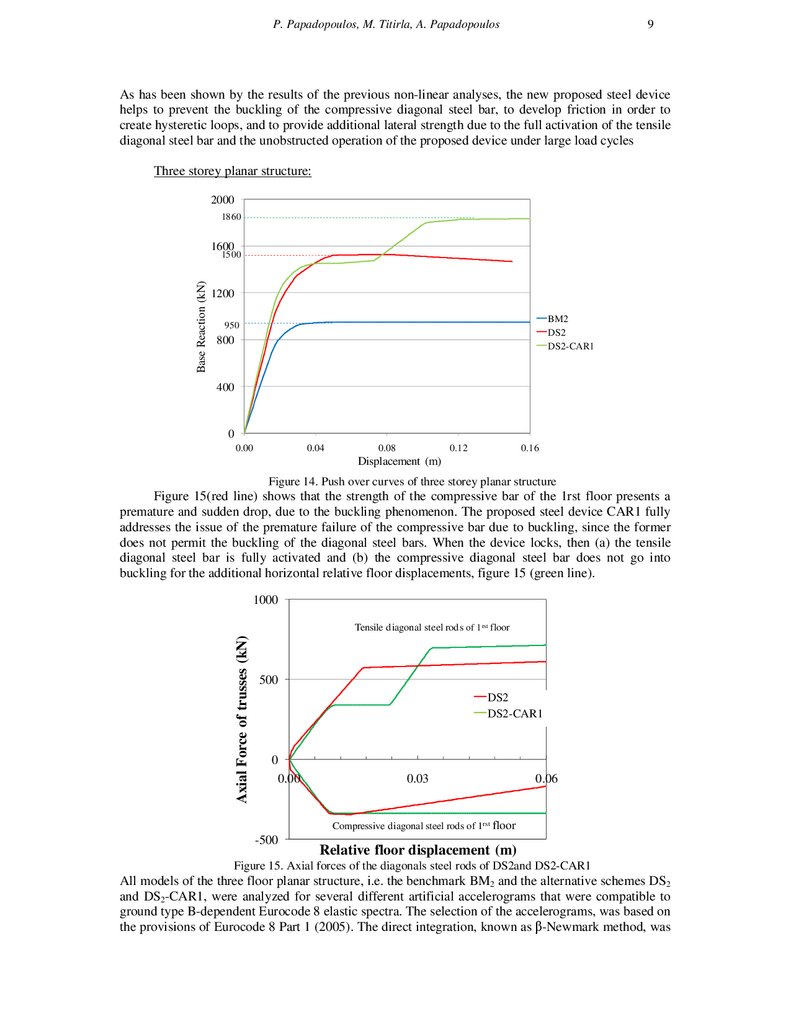
Three storey planar structure:
2000
1860
1600
Base Reaction (kN)
1500
1200
BM2
DS2
DS2-CAR1
950
800
400
0
0.00
0.04
0.08
0.12
0.16
Displacement (m)
Figure 14. Push over curves of three storey planar structure
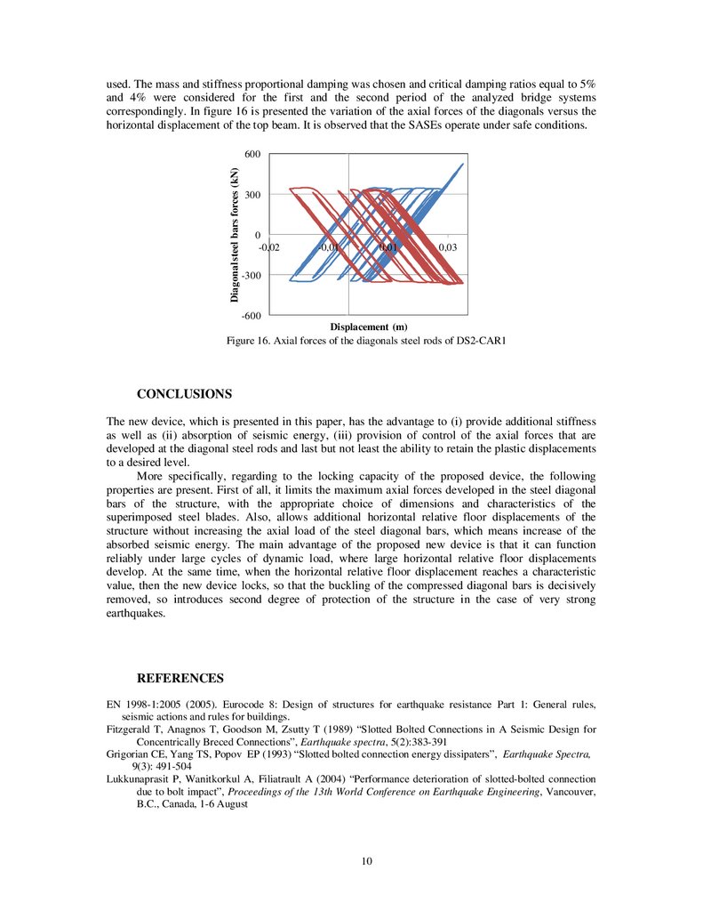
Figure 15(red line) shows that the strength of the compressive bar of the 1rst floor presents a
premature and sudden drop, due to the buckling phenomenon. The proposed steel device CAR1 fully
addresses the issue of the premature failure of the compressive bar due to buckling, since the former
does not permit the buckling of the diagonal steel bars. When the device locks, then (a) the tensile
diagonal steel bar is fully activated and (b) the compressive diagonal steel bar does not go into
buckling for the additional horizontal relative floor displacements, figure 15 (green line).
1000
Axial Force of trusses (kN)
Tensile diagonal steel rods of 1 rst floor
500
DS2
DS2-CAR1
0
0.00
0.03
0.06
Compressive diagonal steel rods of 1rst floor
-500
Relative floor displacement (m)
Figure 15. Axial forces of the diagonals steel rods of DS2and DS2-CAR1
All models of the three floor planar structure, i.e. the benchmark BM2 and the alternative schemes DS2
and DS2-CAR1, were analyzed for several different artificial accelerograms that were compatible to
ground type B-dependent Eurocode 8 elastic spectra. The selection of the accelerograms, was based on
the provisions of Eurocode 8 Part 1 (2005). The direct integration, known as β-Newmark method, was
10.
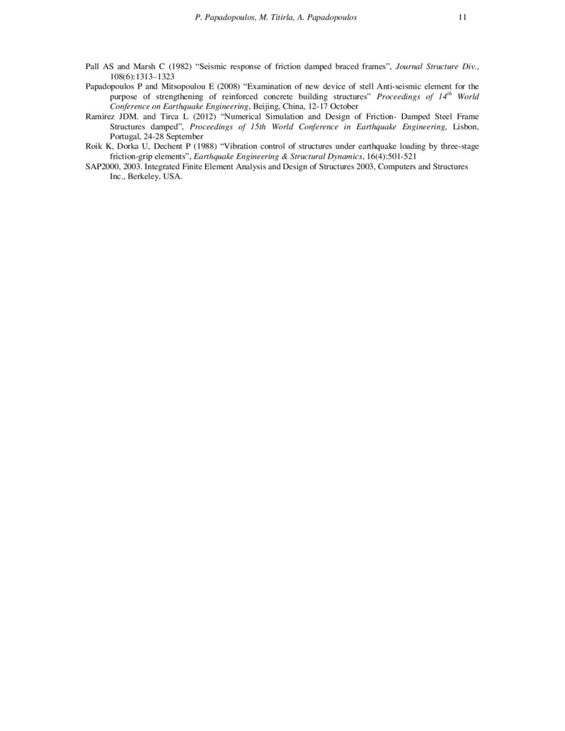
used. The mass and stiffness proportional damping was chosen and critical damping ratios equal to 5%and 4% were considered for the first and the second period of the analyzed bridge systems
correspondingly. In figure 16 is presented the variation of the axial forces of the diagonals versus the
horizontal displacement of the top beam. It is observed that the SASEs operate under safe conditions.
Diagonal steel bars forces (kN)
600
300
0
-0,02
-0,01
0,01
0,03
-300
-600
Displacement (m)
Figure 16. Axial forces of the diagonals steel rods of DS2-CAR1
CONCLUSIONS
The new device, which is presented in this paper, has the advantage to (i) provide additional stiffness
as well as (ii) absorption of seismic energy, (iii) provision of control of the axial forces that are
developed at the diagonal steel rods and last but not least the ability to retain the plastic displacements
to a desired level.
More specifically, regarding to the locking capacity of the proposed device, the following
properties are present. First of all, it limits the maximum axial forces developed in the steel diagonal
bars of the structure, with the appropriate choice of dimensions and characteristics of the
superimposed steel blades. Also, allows additional horizontal relative floor displacements of the
structure without increasing the axial load of the steel diagonal bars, which means increase of the
absorbed seismic energy. The main advantage of the proposed new device is that it can function
reliably under large cycles of dynamic load, where large horizontal relative floor displacements
develop. At the same time, when the horizontal relative floor displacement reaches a characteristic
value, then the new device locks, so that the buckling of the compressed diagonal bars is decisively
removed, so introduces second degree of protection of the structure in the case of very strong
earthquakes.
REFERENCES
EN 1998-1:2005 (2005). Eurocode 8: Design of structures for earthquake resistance Part 1: General rules,
seismic actions and rules for buildings.
Fitzgerald T, Anagnos T, Goodson M, Zsutty T (1989) “Slotted Bolted Connections in A Seismic Design for
Concentrically Breced Connections”, Earthquake spectra, 5(2):383-391
Grigorian CE, Yang TS, Popov EP (1993) “Slotted bolted connection energy dissipaters”, Earthquake Spectra,
9(3): 491-504
Lukkunaprasit P, Wanitkorkul A, Filiatrault A (2004) “Performance deterioration of slotted-bolted connection
due to bolt impact”, Proceedings of the 13th World Conference on Earthquake Engineering, Vancouver,
B.C., Canada, 1-6 August
10
11.
P. Papadopoulos, M. Titirla, A. Papadopoulos11
Pall AS and Marsh C (1982) “Seismic response of friction damped braced frames”, Journal Structure Div.,
108(6):1313–1323
Papadopoulos P and Mitsopoulou E (2008) “Examination of new device of stell Anti-seismic element for the
purpose of strengthening of reinforced concrete building structures” Proceedings of 14th World
Conference on Earthquake Engineering, Beijing, China, 12-17 October
Ramirez JDM. and Tirca L (2012) “Numerical Simulation and Design of Friction- Damped Steel Frame
Structures damped”, Proceedings of 15th World Conference in Earthquake Engineering, Lisbon,
Portugal, 24-28 September
Roik K, Dorka U, Dechent P (1988) “Vibration control of structures under earthquake loading by three-stage
friction-grip elements”, Earthquake Engineering & Structural Dynamics, 16(4):501-521
SAP2000, 2003. Integrated Finite Element Analysis and Design of Structures 2003, Computers and Structures
Inc., Berkeley, USA.