 Construction
Similar presentations:
")


Chapter 1. Introduction
1.
CHAPTER 1Introduction
1.1 GENERAL
The damage caused by seismic events has driven structural engineers to figure out
cost-efficient solutions with the aim to reduce the demand triggered in structural
members of buildings. In this regard, by adding supplemental damping to a structural
system, the damage energy is reduced and the inelastic response of earthquake resistant
members is controlled. In general, damping can be added by incorporating passive or/and
active energy dissipaters. When passive dampers are selected, for instance friction
dampers, they are able to use the seismic demand translated in term of displacement
induced into the structural system in order to activate the friction mechanism.
In light of this, Pall friction dampers have been widely used in North America
either in new or retrofit design projects of steel or reinforced concrete structure (e.g. A.
Pall et al. 1987; Soli et al, 1996; Sadek et al.1996; Vail et al. 2004; Pasquin et al. 2004
and others). These devices dissipate energy through the relative sliding of plates clamped
by post-tensioned bolts. The experimental studies conducted by Pall (1979) identified
clearly that sliding along the available slip distance is controlled by the length of slotted
hole and the behaviour is similar to that of an elastic-perfectly plastic system. However,
under a large seismic input, the post-tensioned bolts belonging to the friction damper
1
2.
device may undergo an additional phase following sliding, characterised by bearing ofbolts or adjacent plates. Thus, in this stage, a sudden increment in storey shear force
accompanied by decreasing of supplemental damping is encountered. Therefore, the
behaviour of friction damper can be divided in three phases as follows: “stick-slip”
before sliding occurs, “slipping”, and the “slip-lock” when the force in the device is
increased due to the bearing of the bolts. Nevertheless, in literature, there are no reported
test results concerning the failure of Pall friction damper due to bearing or shearing of
post-tensioned bolts, although this phenomena has been anticipated (Pall 1979). Later on,
Roik et al. (1988) and Lukkunaprasit et al. (2004) performed cyclic tests where they
showed that a possible “bolt-impact” occurred if the demand has lead the sliding plates to
enter in contact with the post-tensioned bolts. Lukkunaprasit et al. (2004) evidenced that
this jump in force resistant at bearing is limited by failure of friction device. In addition,
degradation in the hysteresis capacity of device was observed after the bolt impacted the
slotted hole and a sudden loss of post-tension force in the bolts occurred. When the
bearing phase is considered, an increment in the base shear was noticed.
Previous studies have used mainly elastic-plastic models which considered only
the rectangular hysteresis shape characterised by the dry Coulomb friction, while the
bearing phase has been ignored. Other researchers have developed multi-linear models to
incorporate the bearing phase, but Lukkunaprasit et al. (2004), have pointed out that
previous studies did not take into account the nonlinear behaviour neither the decoupling
of the device from structure when failure was encountered.
The current provisions of NBCC 2010 do not provide guidelines regarding
earthquake resistant structures equipped with friction damper devices nor suggestions
2
3.
referring at adding damping into a structural system in order to reduce the seismicdemand. Although FEMA 356 (2000) contains information regarding friction devices and
some design recommendations such as “all energy dissipation devices shall be capable of
sustaining displacements equal to 130% of the maximum calculated displacement in the
device” when subjected to ground motions defined for 2% in 50 years probability of
exceedance, it does not stipulate complete design provisions.
1.2 OBJECTIVES AND SCOPE
The scope of this research is to develop a numerical model able to simulate the
seismic response of a moment resisting frame structure equipped with friction-damped
diagonal-bracing devices and to emphasise the behaviour of the 4-, 8- and 12-storey
building located in Montreal when a minimum of four dampers per floor have been
installed as follows: i) at each floor; ii) at alternative floors; and ii) staggered at reduced
number of floors. Herein, the identified engineering demand parameters are reported
based on their mean and the 84th percentile and are obtained from time-history analyses
of the aforementioned buildings subjected to 15 simulated and historical ground motions.
In addition, until today, there is not an accurate computer model reported in literature
able to capture the complexity of the real friction damper behaviour and the response of
earthquake resistant structure with friction dampers incorporated.
Thus, the objectives of this study are:
3
4.
To develop a computer model of friction damper device able to integrate the threephases pointed out by Lukkunaprasit et al. (2004): stick-slip; slipping or sliding;
and the slip-lock by using the finite element library of the OpenSees software.
To develop a design method in order to compute the number of devices per floor,
the slip force and the required slip distance.
To analyse the performance of the 4-, 8-, and 12- storey buildings equipped with
energy dissipative devices such as friction-damped diagonal-bracing system.
The seismic response is discussed based on three scenarios of dampers‟ locations
and by considering two simulated models: with and without slip-lock phase incorporated.
Based on numerical results, the effect of bearing phase on the adjacent structural
members is emphasised. It is assumed that no degradation of the hysteresis loop occurred
during the friction damper response and the diagonal-bracing system is designed to
behave elastically.
1.3 DESCRIPTION OF METHODOLOGY
To simulate in OpenSees software framework the first two behavioural phases of
Pall friction dampers: stick-slip and slipping, the Bouc-Wen material characterized by
smooth transition from elastic to plastic was employed. The main parameters required to
define the Bouc-Wen material are: the slip-force and the available slip-distance which
was calibrated through parametric studies. In addition, earlier experimental tests
conducted by Pall (1979) were used to control the calibration. The slip-lock phase
occurred due to bearing of post-tensioned bolts and is simulated by adding Elastic4
5.
Perfectly plastic Gap material object in parallel to the Bouc-Wen material. Fordecoupling the device from the system at failure, when bearing force equates the bearing
strength, the MinMax material object was assigned to the ensemble of Bouc-Wen and the
Elastic Perfect plastic Gap material. In order to complete the modelling of frictiondamped diagonal-bracing device, the action in series of the elastic brace and the defined
friction damper is considered.
The design technique proposed herein to define the number of dampers per floor
and the assigned slip-load is based on minimizing the damage energy absorbed into the
bare frame system such that the moment resisting frame members to behave elastically.
In this context, the MRF is considered to be simultaneously a backup system and a recentering system.
The proposed hysteresis model, able to simulate the behaviour of friction-damped
diagonal-bracing system, is incorporated into the OpenSees framework of 4-, 8-, and 12storey MRF buildings. Herein, force-base nonlinear beam-column elements (beam with
hinges) were selected to simulate the behaviour of MRF‟s members and Steel02 material
(known as uniaxial Giuffre- Menegotto-Pinto steel material) was assigned. Time-history
nonlinear analyses were conducted for each case study located in Montreal and subjected
to 15 simulated and historical records, scaled to fit the uniform hazard spectrum (UHS) of
2% in 50 years probability of exceedance. For each case study, three different scenarios
of dampers location along the building height were considered, while the device model
was defined with and without slip distance limitation.
5
6.
1.4 THESIS ORGANISATIONThe first chapter summarises the scope of this research, the objectives and the
applied methodology.
In Chapter 2 a detailed literature review regarding friction damper devises is
illustrated in addition to the presentation of Bouc-Wen hysteresis model through
mathematical equations.
The Chapter 3 focuses on establishing a computer model able to simulate the
three-phase behavior of the friction damper installed in diagonal-bracing system by using
OpenSees software framework (open system for seismic simulation). In light of this, the
Bouc-Wen material characterized by smooth transition from elastic to plastic was
calibrated through parametric study in order to characterize the first two behavioural
phases mainly controlled by the slip-force and available slip-distance. The slip-lock phase
due to bearing exhibited when the post-tensioned bolts impact the edge of the slotted hole
is simulated by adding in parallel to the Bouc-Wen material the uniaxial Elastic Perfectly
plastic Gap material. At the end of the chapter, a brace with friction device was
numerically simulated in OpenSees and studied under quasi-static displacement loading.
Chapter 4 illustrates the behavior of the 4, 8 and 12-storey building designed as
moderately ductile (MD) moment resisting frame structure accordingly to NBCC 2010
and CSA/S16-2009. Herein, the MD-MRF system was selected versus conventional MRF
due to its cost-efficiency and capability to behave elastically when friction damper
devices are installed. In addition, the purpose of considering moment frame structure as a
6
7.
bare frame for dampers installation is to have a backup system during the time whendampers are activated. In this study, the MD-MRF structure are analysed for comparison
purpose and are subjected to 15 simulated and historical ground motions scaled to match
the uniform hazard spectrum. In this study, the following parameters were selected to
capture the seismic response: interstorey drift, drift angle and maximum rotation demand
after plastic hinges were formed in beams.
In Chapter 5 the seismic response of MD-MRF structures equipped with frictiondamped diagonal-bracing system devices is analyzed through numerical simulations.
First, the design technique consisting of defining the number of dampers per floor and the
assigned slip-load is carried out based on minimizing the damage energy in the bare
frame system. Three different scenarios of friction-damped diagonal-bracing devices
location and the available slip-distance parameter are considered herein. Numerical
analyses are conducted under the 15 selected records and results are expressed based on a
statistical distribution.
Finally, Chapter 6 provides conclusions and future work recommendations
resulted from this research work.
7
8.
CHAPTER 2Literature Review
2.1 PASSIVE ENERGY DISSIPATION DEVICES
A continued increase of human population and its concentration in urban areas
have triggered the development of infrastructure and building constructions.
In general, the total input energy (EI) induced by a seismic event into a structural
system can be expressed as a summation of kinetic energy, Ek, cumulative strain energy,
ES, inherent damping, ED and the hysteretic damping or the post-yield hysteretic damping
of the seismic force resistant system (SFRS), Eh which in this case is the damping
induced by friction devices (Foliente 1993; Filiatrault 1997). The energy balance
equation is:
(2.1)
The kinetic and cumulative strain energy are accumulated by the primary
structural system and are related to the structural damage (Akiyama 2000; Tirca et al.
2010), while both ED and Eh are amplitude-dependent and able to damp the SFRS. In
general, the contribution of ED and Eh is related to the amount of post-yielding response.
Rearranging terms of Equation (2.1) gives:
8
9.
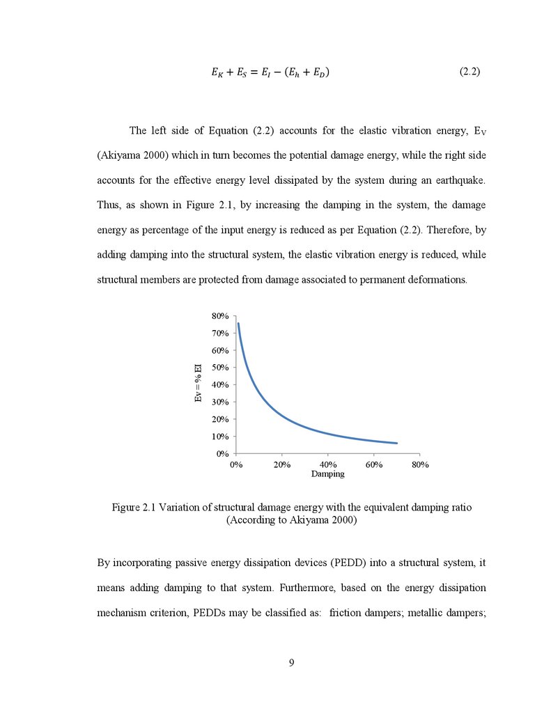
(2.2)The left side of Equation (2.2) accounts for the elastic vibration energy, EV
(Akiyama 2000) which in turn becomes the potential damage energy, while the right side
accounts for the effective energy level dissipated by the system during an earthquake.
Thus, as shown in Figure 2.1, by increasing the damping in the system, the damage
energy as percentage of the input energy is reduced as per Equation (2.2). Therefore, by
adding damping into the structural system, the elastic vibration energy is reduced, while
structural members are protected from damage associated to permanent deformations.
80%
70%
Ev = % EI
60%
50%
40%
30%
20%
10%
0%
0%
20%
40%
Damping
60%
80%
Figure 2.1 Variation of structural damage energy with the equivalent damping ratio
(According to Akiyama 2000)
By incorporating passive energy dissipation devices (PEDD) into a structural system, it
means adding damping to that system. Furthermore, based on the energy dissipation
mechanism criterion, PEDDs may be classified as: friction dampers; metallic dampers;
9
10.
viscoelastic dampers; viscous fluid dampers; and tuned mass dampers (Soong andDargush 1997).
Friction dampers dissipate energy through friction developed by the relative
sliding within two surfaces in contact. If an adequate surface treatment and lining
material is applied, their behaviour is characterized by a rectangular stable hysteresis loop
similar to that of Columb friction (A. Pall 1979).Thus, the following dampers are
designed to dissipate energy by friction: slotted bolted connections (Grigorian et al.
1992); Pall friction devices (Pall 1979); Sumitomo damper devices (Aiken et al. 1990 and
1993) and energy dissipating restraint damper (EDR) developed by Flour Daniel Inc.
(Nims et al.1993). A description of each type of friction dampers is given below.
2.2 FRICTION DAMPERS
2.2.1 Limited Slip Bolted Joint and Pall Friction Dampers:
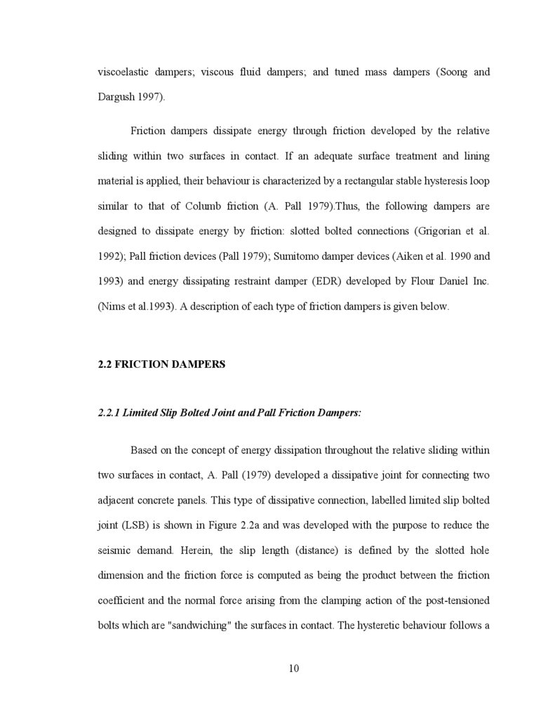
Based on the concept of energy dissipation throughout the relative sliding within
two surfaces in contact, A. Pall (1979) developed a dissipative joint for connecting two
adjacent concrete panels. This type of dissipative connection, labelled limited slip bolted
joint (LSB) is shown in Figure 2.2a and was developed with the purpose to reduce the
seismic demand. Herein, the slip length (distance) is defined by the slotted hole
dimension and the friction force is computed as being the product between the friction
coefficient and the normal force arising from the clamping action of the post-tensioned
bolts which are "sandwiching" the surfaces in contact. The hysteretic behaviour follows a
10
11.
smooth rectangular shape which is characteristic to Coulomb friction law. However, thereal hysteresis shape may be largely influenced by the fluctuation of the friction
coefficient during the slipping process. These variations might be originated by diverse
factors such as temperature, wear effects, loss of the pretension load, and others (Pall
1979; Bondonet and Filiatrault 1997; Sextro 2002). In light of this, Pall has carried out
several experimental tests under monotonic and quasi-static cyclic loading in order to
select the type of surface treatment and lining material that are able to provide a stable
friction coefficient. The hysteresis behaviour of six case studies such as: mill scale, sand
blasted, inorganic zinc-rich paint, metalized, brake lining pads and polyethylene coating
are shown in Figure 2.2b In conclusion, Pall has reported that the most stable behavior
under the static and dynamic tests was obtained when brake lining pads in contact with
mill scale surface on plates was chosen. During the performed quasi-static cyclic tests,
the corresponding hysteretic behaviour did not show appreciable degradation. However, a
minor difference between the static and slip (dynamic) coefficient of friction remained
and is shown in Table 2.1.
Table 2.1 Degradation of hysteretic behavior (after Pall 1979)
Surface finish
Degradation factor (ratio between the
average energy per cycle after 20 cycles
and the energy dissipated in the 1st cycle)
Mill scale
Sand blasted
Zinc-rich paint
Metalized
Brake lining pads over mill scale surface
Brake lining pads over sand blasted surface
Brake lining pads over galvanized surface
P.V.C coating on sand blasted surface
Polyethylene coating over sand blasted surface
0.88
0.98
0.66
1.27
0.98
0.82
0.78
1.8
1.08
11
12.
b)a)
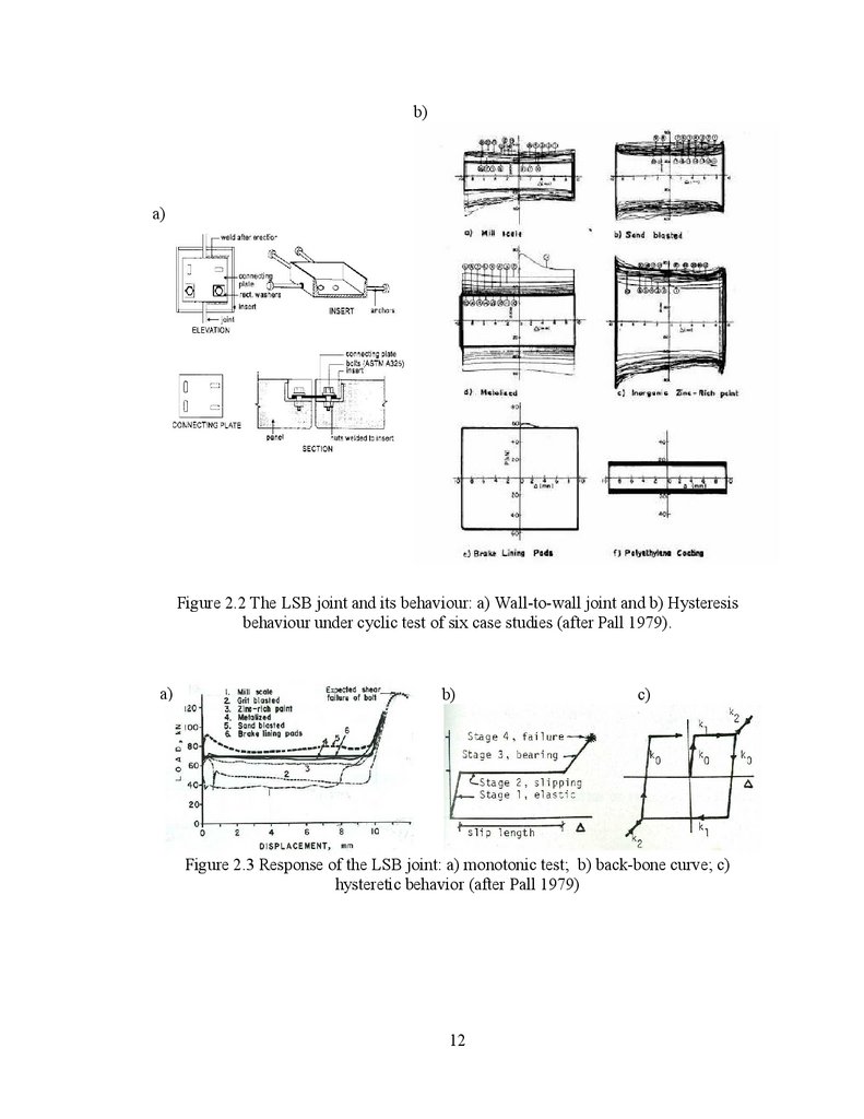
Figure 2.2 The LSB joint and its behaviour: a) Wall-to-wall joint and b) Hysteresis
behaviour under cyclic test of six case studies (after Pall 1979).
a)
b)
c)
Figure 2.3 Response of the LSB joint: a) monotonic test; b) back-bone curve; c)
hysteretic behavior (after Pall 1979)
12
13.
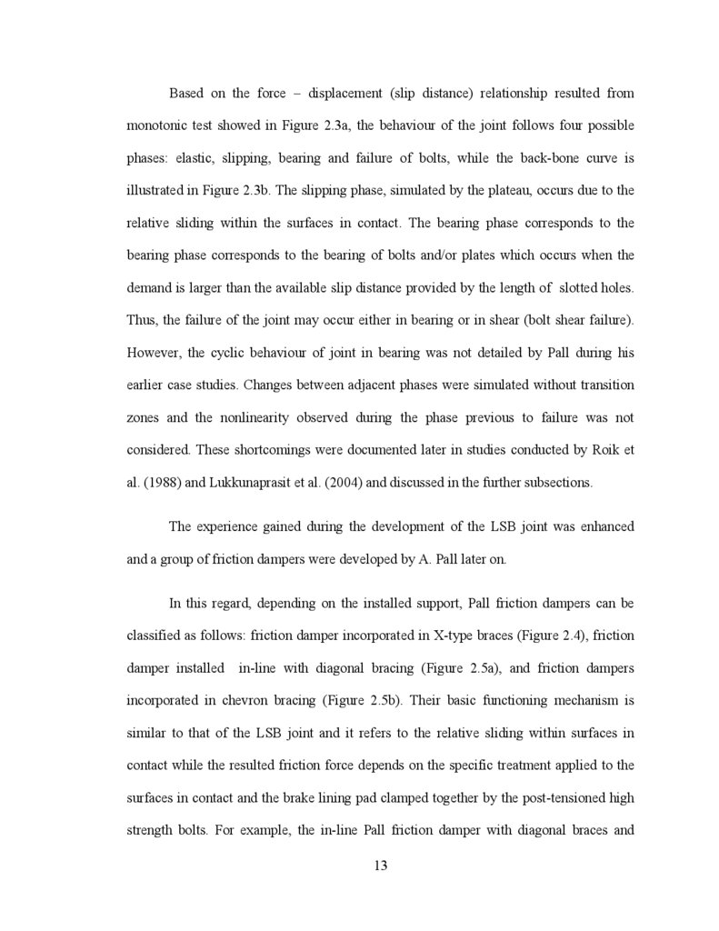
Based on the force – displacement (slip distance) relationship resulted frommonotonic test showed in Figure 2.3a, the behaviour of the joint follows four possible
phases: elastic, slipping, bearing and failure of bolts, while the back-bone curve is
illustrated in Figure 2.3b. The slipping phase, simulated by the plateau, occurs due to the
relative sliding within the surfaces in contact. The bearing phase corresponds to the
bearing phase corresponds to the bearing of bolts and/or plates which occurs when the
demand is larger than the available slip distance provided by the length of slotted holes.
Thus, the failure of the joint may occur either in bearing or in shear (bolt shear failure).
However, the cyclic behaviour of joint in bearing was not detailed by Pall during his
earlier case studies. Changes between adjacent phases were simulated without transition
zones and the nonlinearity observed during the phase previous to failure was not
considered. These shortcomings were documented later in studies conducted by Roik et
al. (1988) and Lukkunaprasit et al. (2004) and discussed in the further subsections.
The experience gained during the development of the LSB joint was enhanced
and a group of friction dampers were developed by A. Pall later on.
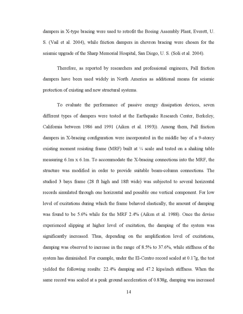
In this regard, depending on the installed support, Pall friction dampers can be
classified as follows: friction damper incorporated in X-type braces (Figure 2.4), friction
damper installed
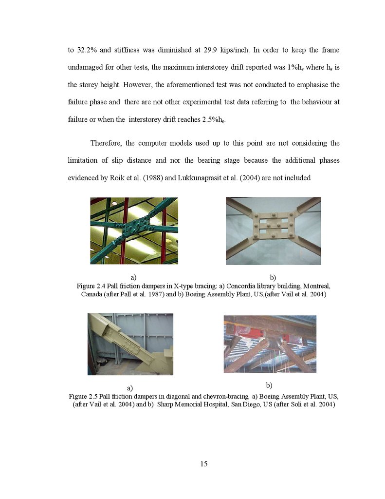
in-line with diagonal bracing (Figure 2.5a), and friction dampers
incorporated in chevron bracing (Figure 2.5b). Their basic functioning mechanism is
similar to that of the LSB joint and it refers to the relative sliding within surfaces in
contact while the resulted friction force depends on the specific treatment applied to the
surfaces in contact and the brake lining pad clamped together by the post-tensioned high
strength bolts. For example, the in-line Pall friction damper with diagonal braces and
13
14.
dampers in X-type bracing were used to retrofit the Boeing Assembly Plant, Everett, U.S. (Vail et al. 2004), while friction dampers in chevron bracing were chosen for the
seismic upgrade of the Sharp Memorial Hospital, San Diego, U. S. (Soli et al. 2004).
Therefore, as reported by researchers and professional engineers, Pall friction
dampers have been used widely in North America as additional means for seismic
protection of existing and new structural systems.
To evaluate the performance of passive energy dissipation devices, seven
different types of dampers were tested at the Earthquake Research Center, Berkeley,
California between 1986 and 1991 (Aiken et al. 1993)). Among them, Pall friction
dampers in X-bracing configuration were incorporated in the middle bay of a 9-storey
existing moment resisting frame (MRF) built at ¼ scale and tested on a shaking table
measuring 6.1m x 6.1m. To accommodate the X-bracing connections into the MRF, the
structure was modified in order to provide suitable beam-column connections. The
studied 3 bays frame (28 ft high and 18ft wide) was subjected to several horizontal
records simulated through one horizontal and possible one vertical component. For low
level of excitations during which the frame behaved elastically, the amount of damping
was found to be 5.6% while for the MRF 2.4% (Aiken et al. 1988). Once the devise
experienced slipping at higher level of excitation, the damping of the system was
significantly increased. Thus, depending on the amplification level of excitations,
damping was observed to increase in the range of 8.5% to 37.6%, while stiffness of the
system has diminished. For example, under the El-Centro record scaled at 0.17g, the test
yielded the following results: 22.4% damping and 47.2 kips/inch stiffness. When the
same record was scaled at a peak ground acceleration of 0.838g, damping was increased
14
15.
to 32.2% and stiffness was diminished at 29.9 kips/inch. In order to keep the frameundamaged for other tests, the maximum interstorey drift reported was 1%hs where hs is
the storey height. However, the aforementioned test was not conducted to emphasise the
failure phase and there are not other experimental test data referring to the behaviour at
failure or when the interstorey drift reaches 2.5%hs.
Therefore, the computer models used up to this point are not considering the
limitation of slip distance and nor the bearing stage because the additional phases
evidenced by Roik et al. (1988) and Lukkunaprasit et al. (2004) are not included
a)
b)
Figure 2.4 Pall friction dampers in X-type bracing: a) Concordia library building, Montreal,
Canada (after Pall et al. 1987) and b) Boeing Assembly Plant, US,(after Vail et al. 2004)
b)
a)
Figure 2.5 Pall friction dampers in diagonal and chevron-bracing a) Boeing Assembly Plant, US,
(after Vail et al. 2004) and b) Sharp Memorial Hospital, San Diego, US (after Soli et al. 2004)
15
16.
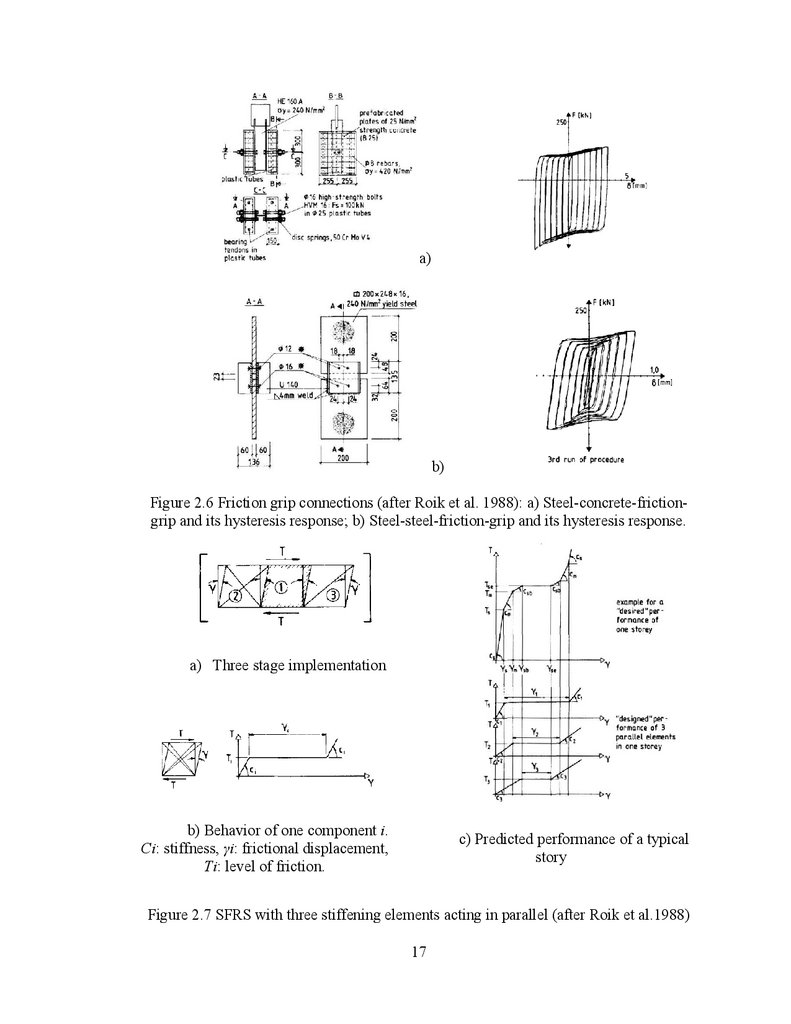
2.2.2 Fiction Grip Connections:Based on the work done by A. Pall and employing the mechanism of friction
within two solid surfaces, Roik et al. (1988) proposed a three-stage friction-grip
connection able to be designed for serviceability, life-safety and collapse prevention limit
state under seismic loads. Experimental tests were conducted on steel-steel and steelconcrete friction-grip joints in order to provide a mechanism of energy dissipation
(Figure 2.6). Based on tests, they concluded that coupling in parallel the displacement of
three structural elements as shown in Figure 2.7a it smoothes the transition phase from
elastic behaviour to the slipping stage and avoids the induction of possible vibrations.
The force deformation relation of an element is shown in Figure 2.7b, while the predicted
performance of a three-stage stiffening element is illustrated in Figure 2.7c.
It was revealed that stiffness and the nonlinear behavior are depended on the
pretension force applied to the clamping bolts even if no considerable damage occurred
in the joint. When implemented in a building, the mechanical properties of the bolts and
the geometrical limit of slotted holes influence largely the lateral stiffness of each story,
the activation of the slip force and the amount of energy dissipated per cycle.
Therefore, by combining a set of these joints as braking system into a 7-storey
CBF building subjected to seismic actions, an enhancement of the response during a
ground motion event was achieved; meanwhile the slip distance was not exceeded by the
developed interstory drift throughout the duration of excitation during the test.
.
16
17.
a)b)
Figure 2.6 Friction grip connections (after Roik et al. 1988): a) Steel-concrete-frictiongrip and its hysteresis response; b) Steel-steel-friction-grip and its hysteresis response.
a) Three stage implementation
b) Behavior of one component i.
Ci: stiffness, i: frictional displacement,
Ti: level of friction.
c) Predicted performance of a typical
story
Figure 2.7 SFRS with three stiffening elements acting in parallel (after Roik et al.1988)
17
18.
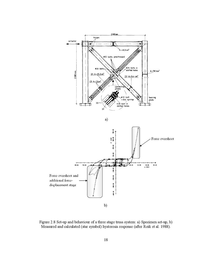
a)b)
Figure 2.8 Set-up and behaviour of a three stage truss system: a) Specimen set-up, b)
Measured and calculated (star symbol) hysteresis response (after Roik et al. 1988).
18
19.
Despite of underlined improvements, the bearing stage due to the bolt impactarose as a consequence of limited slip distance imposed by the length of slotted hole and
the post-tensioned force of high strength bolts. This behaviour shown in Figure 2.8a was
identified in analytical and experimental test conducted on a CBF system by modelling a
three-stage truss system. The hysteresis loop of the specimen tested under the N-S
component of El Centro record provides an insight of the force overshoot due to the bolt
impact that is shown in Figure 2.8b. It is evident that the additional force-displacement
stage encountered was not emphasised in previous tests. As consequence, the model
proposed was unable to capture this further feature.
2.2.3 Slotted Bolted Connections:
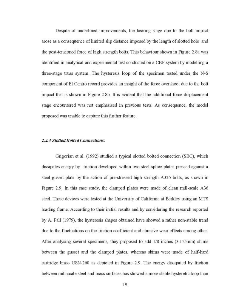
Grigorian et al. (1992) studied a typical slotted bolted connection (SBC), which
dissipates energy by friction developed within two steel splice plates pressed against a
steel gusset plate by the action of pre-stressed high strength A325 bolts, as shown in
Figure 2.9. In this case study, the clamped plates were made of clean mill-scale A36
steel. These devices were tested at the University of California at Berkley using an MTS
loading frame. According to their initial results and by considering the research reported
by A. Pall (1979), the hysteresis shapes obtained have showed a rather non-stable trend
due to the fluctuations on the friction coefficient and abrasive wear effects among other.
After analysing several specimens, they proposed to add 1/8 inches (3.175mm) shims
between the gusset and the clamped plates, whereas shims were made of half-hard
cartridge brass USN-260 as depicted in Figure 2.9. The energy dissipated by friction
between mill-scale steel and brass surfaces has showed a more stable hysteretic loop than
19
20.
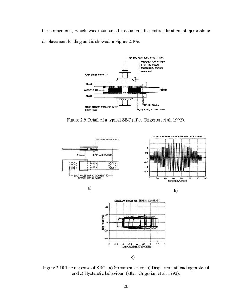
the former one, which was maintained throughout the entire duration of quasi-staticdisplacement loading and is showed in Figure 2.10c.
Figure 2.9 Detail of a typical SBC (after Grigorian et al. 1992).
a)
b)
c)
Figure 2.10 The response of SBC : a) Specimen tested, b) Displacement loading protocol
and c) Hysteretic behaviour :(after Grigorian et al. 1992).
20
21.
Although the trend of the hysteresis cycles followed a rectangular shape as perCoulomb friction law, there are fluctuations within the loop when the sliding surfaces are
exhibited the stick-slip stage due to variation of friction coefficient from static to the
dynamic value. This change may induce additional vibration into the structure which
depends on the variation rate of friction coefficient.
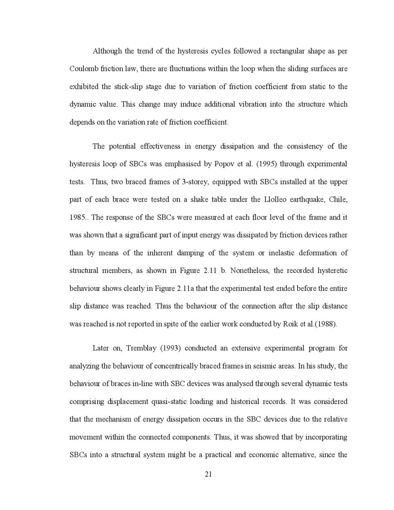
The potential effectiveness in energy dissipation and the consistency of the
hysteresis loop of SBCs was emphasised by Popov et al. (1995) through experimental
tests. Thus, two braced frames of 3-storey, equipped with SBCs installed at the upper
part of each brace were tested on a shake table under the Llolleo earthquake, Chile,
1985.. The response of the SBCs were measured at each floor level of the frame and it
was shown that a significant part of input energy was dissipated by friction devices rather
than by means of the inherent damping of the system or inelastic deformation of
structural members, as shown in Figure 2.11 b. Nonetheless, the recorded hysteretic
behaviour shows clearly in Figure 2.11a that the experimental test ended before the entire
slip distance was reached. Thus the behaviour of the connection after the slip distance
was reached is not reported in spite of the earlier work conducted by Roik et al.(1988).
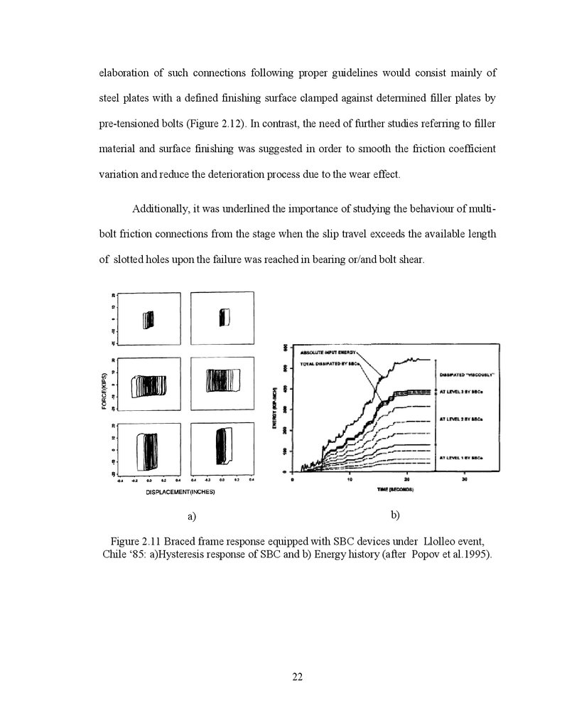
Later on, Tremblay (1993) conducted an extensive experimental program for
analyzing the behaviour of concentrically braced frames in seismic areas. In his study, the
behaviour of braces in-line with SBC devices was analysed through several dynamic tests
comprising displacement quasi-static loading and historical records. It was considered
that the mechanism of energy dissipation occurs in the SBC devices due to the relative
movement within the connected components. Thus, it was showed that by incorporating
SBCs into a structural system might be a practical and economic alternative, since the
21
22.
elaboration of such connections following proper guidelines would consist mainly ofsteel plates with a defined finishing surface clamped against determined filler plates by
pre-tensioned bolts (Figure 2.12). In contrast, the need of further studies referring to filler
material and surface finishing was suggested in order to smooth the friction coefficient
variation and reduce the deterioration process due to the wear effect.
Additionally, it was underlined the importance of studying the behaviour of multibolt friction connections from the stage when the slip travel exceeds the available length
of slotted holes upon the failure was reached in bearing or/and bolt shear.
b)
a)
Figure 2.11 Braced frame response equipped with SBC devices under Llolleo event,
Chile „85: a)Hysteresis response of SBC and b) Energy history (after Popov et al.1995).
22
23.
a)b)
c)
Figure 2.12 CBF with SBCs: a) Test set-up; b) detail of the SBC and. c) Hysteretic
behavior under displacement controlled cyclic test (after Tremblay 1993).
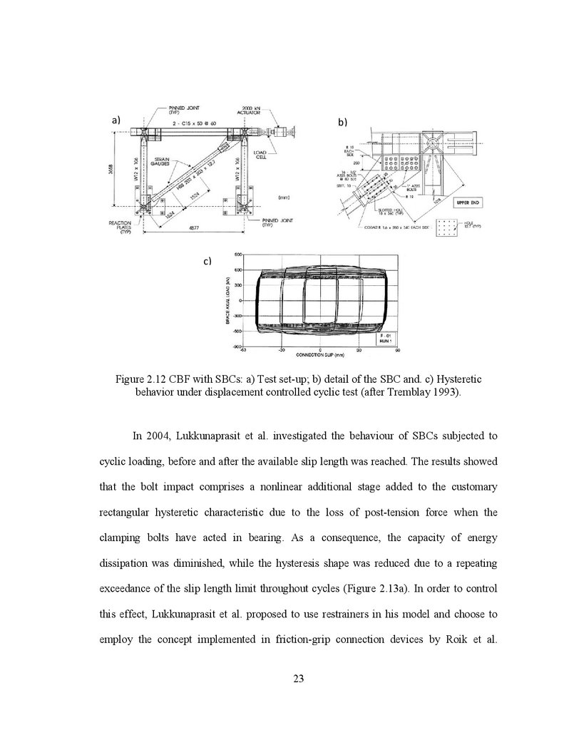
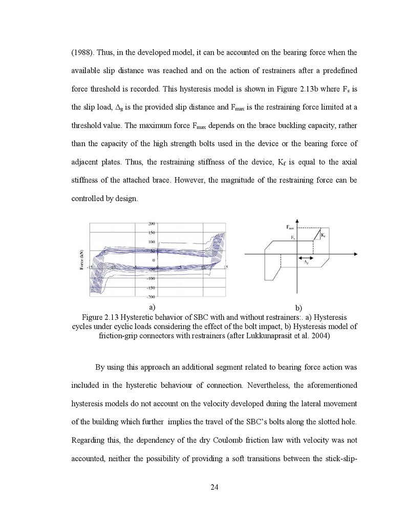
In 2004, Lukkunaprasit et al. investigated the behaviour of SBCs subjected to
cyclic loading, before and after the available slip length was reached. The results showed
that the bolt impact comprises a nonlinear additional stage added to the customary
rectangular hysteretic characteristic due to the loss of post-tension force when the
clamping bolts have acted in bearing. As a consequence, the capacity of energy
dissipation was diminished, while the hysteresis shape was reduced due to a repeating
exceedance of the slip length limit throughout cycles (Figure 2.13a). In order to control
this effect, Lukkunaprasit et al. proposed to use restrainers in his model and choose to
employ the concept implemented in friction-grip connection devices by Roik et al.
23
24.
(1988). Thus, in the developed model, it can be accounted on the bearing force when theavailable slip distance was reached and on the action of restrainers after a predefined
force threshold is recorded. This hysteresis model is shown in Figure 2.13b where Fs is
the slip load, Δg is the provided slip distance and Fmax is the restraining force limited at a
threshold value. The maximum force Fmax depends on the brace buckling capacity, rather
than the capacity of the high strength bolts used in the device or the bearing force of
adjacent plates. Thus, the restraining stiffness of the device, Kf is equal to the axial
stiffness of the attached brace. However, the magnitude of the restraining force can be
controlled by design.
a)
b)
Figure 2.13 Hysteretic behavior of SBC with and without restrainers:. a) Hysteresis
cycles under cyclic loads considering the effect of the bolt impact, b) Hysteresis model of
friction-grip connectors with restrainers (after Lukkunaprasit et al. 2004)
By using this approach an additional segment related to bearing force action was
included in the hysteretic behaviour of connection. Nevertheless, the aforementioned
hysteresis models do not account on the velocity developed during the lateral movement
of the building which further implies the travel of the SBC‟s bolts along the slotted hole.
Regarding this, the dependency of the dry Coulomb friction law with velocity was not
accounted, neither the possibility of providing a soft transitions between the stick-slip-
24
25.
stage to the slipping stage nor the option of a gradual nonlinear transition from slipping tobearing or slip-lock stage when the post-tensioned bolts are pushed beyond the elastic
behavior as is shown on Figure 2.13a. Since the response of a structural system depends
on the frequency content of ground motions, it is required that the hysteresis model of
friction devices to incorporate the following features: stick-slip changes, the relative
velocity dependency, the simulation of bearing stage and the gradual nonlinear transition.
Furthermore, a gradual change in the neighbouring zones of transition points such as
stick-slip and slip-lock is desired in order to reduce the overshoot in forces due to the
high nonlinearity occurred during the dynamic response (Gear 1971, Casarotti 2004;
Bathe 2006; and Strang 2007).
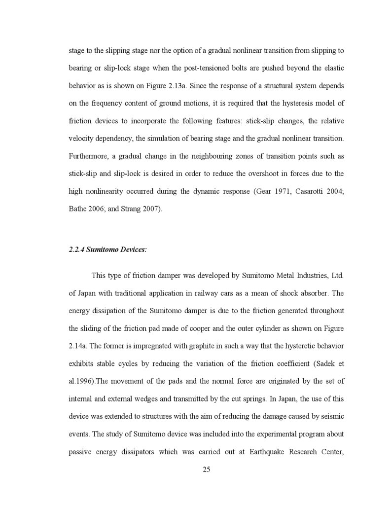
2.2.4 Sumitomo Devices:
This type of friction damper was developed by Sumitomo Metal Industries, Ltd.
of Japan with traditional application in railway cars as a mean of shock absorber. The
energy dissipation of the Sumitomo damper is due to the friction generated throughout
the sliding of the friction pad made of cooper and the outer cylinder as shown on Figure
2.14a. The former is impregnated with graphite in such a way that the hysteretic behavior
exhibits stable cycles by reducing the variation of the friction coefficient (Sadek et
al.1996).The movement of the pads and the normal force are originated by the set of
internal and external wedges and transmitted by the cut springs. In Japan, the use of this
device was extended to structures with the aim of reducing the damage caused by seismic
events. The study of Sumitomo device was included into the experimental program about
passive energy dissipators which was carried out at Earthquake Research Center,
25
26.
Berkeley (Aiken et al. 1990; 1993). The tests related to the Sumitomo friction damperinstalled in-line with braces were done in a ¼ scale 9-story MRF specimen, shown
schematically in Figure 2.14b. It was concluded that Sumitomo dampers incorporated in a
frame system are able to reduce the frame displacements, to increase damping in the
system and to dissipate a significant amount of input energy by friction following the
rectangular hysteresis pattern (Figure 2.14c).
b) ¼ scale 9-story friction damped MRF
specimen
a) Sumitomo friction damper
c) Typical hysteretic behavior of one friction
damper
Figure 2.14 Sumitomo friction damper (after Aiken et al. 1990))
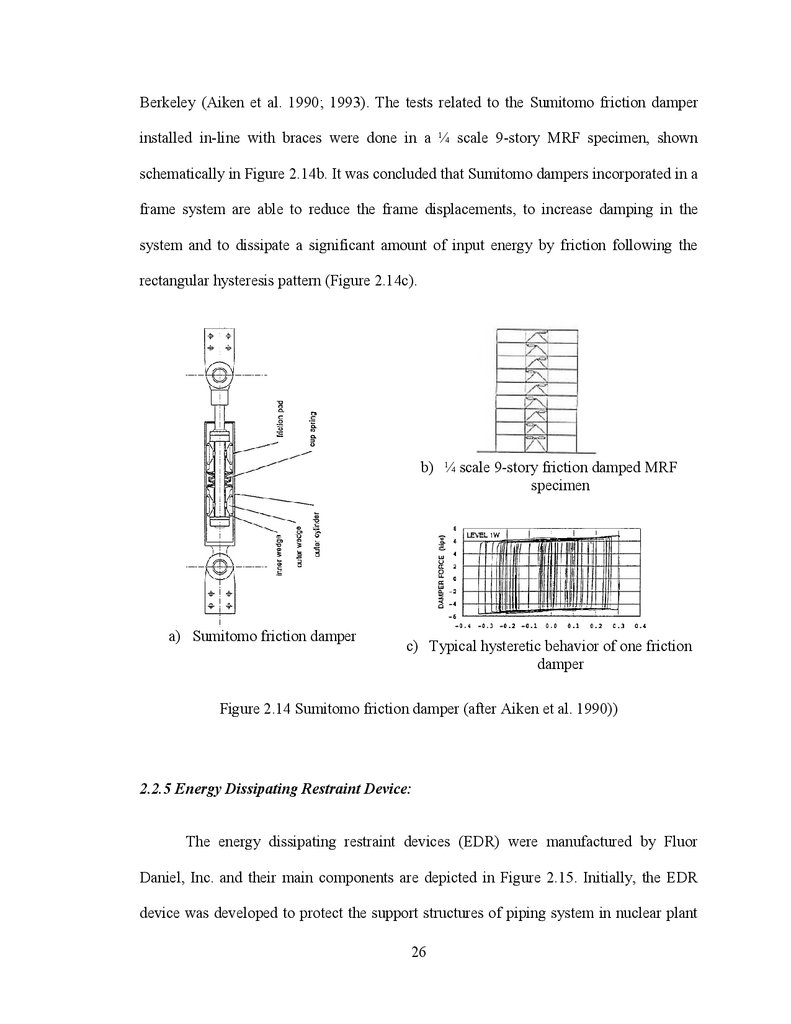
2.2.5 Energy Dissipating Restraint Device:
The energy dissipating restraint devices (EDR) were manufactured by Fluor
Daniel, Inc. and their main components are depicted in Figure 2.15. Initially, the EDR
device was developed to protect the support structures of piping system in nuclear plant
26
27.
against seismic loads. The EDE device is similar to the Sumitomo device in term ofcomponents: internal spring, wedges, pads, external cylinder. Their mechanism and
functioning might appear to be alike (Nims et al.1993) but some behaviour aspects are
different. In this light, Soong and Dargush (1997) and Zhou and Peng. (2009) concluded:
i) The friction force depends on the axial force of the spring that is transformed into a
normal pressure acting outwards against the cylinder wall by the wedges. on the other
hand, the elastic action of the internal spring and the triangular basic hysteresis
characteristic, are making the EDR self centering when the external load is reduced to
zero without residual deformation. Furthermore, the internal stops allow tension and
compression gaps that might be adjusted as required.
ii) For different adjustments of the device such as the variation of the precompressive force applied to the spring and the distance between the nuts and the stops
yields to different hysteresis shapes as shown in Figure 2.15b, c and d. (Nims et al.1993).
The EDR device induces stiffness and damping into the system. Nevertheless, the
work done by Nims et al. (1993) evidenced that the EDR friction force is very low for
practical structural systems and its functioning depends largely on the internal spring
which is able to carry a limited force without losing its deformability.
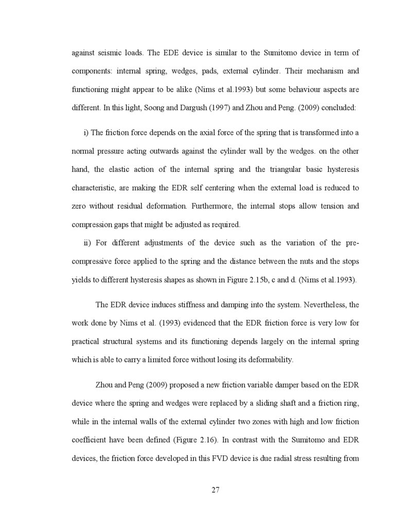
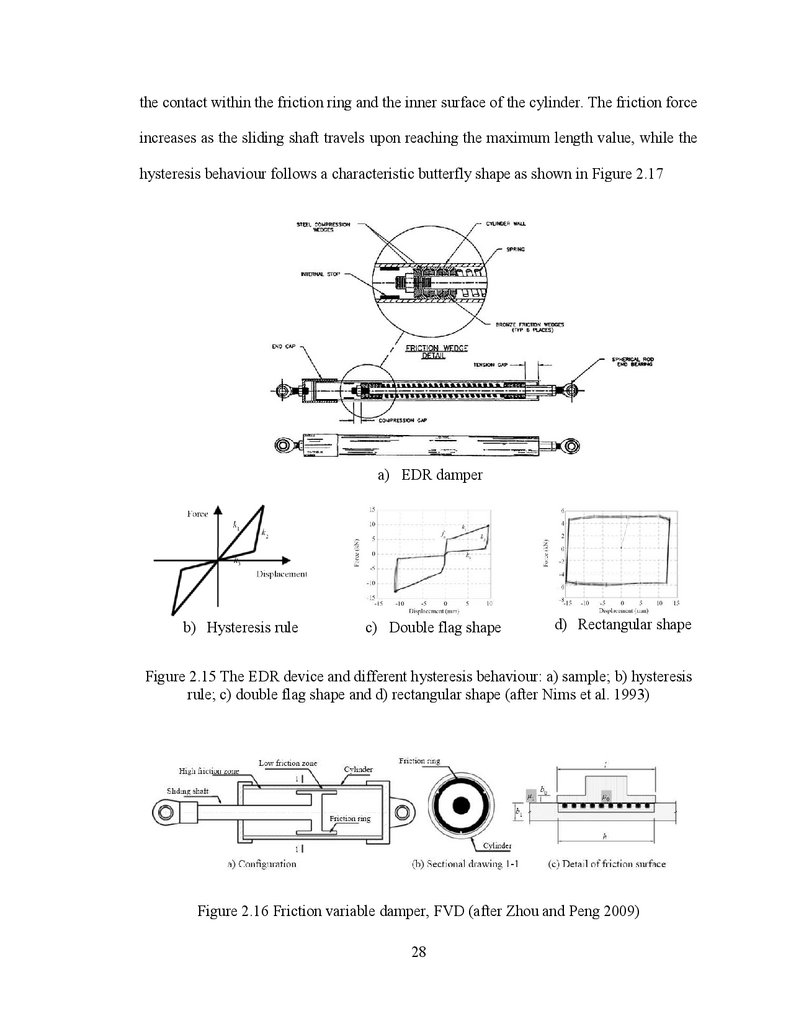
Zhou and Peng (2009) proposed a new friction variable damper based on the EDR
device where the spring and wedges were replaced by a sliding shaft and a friction ring,
while in the internal walls of the external cylinder two zones with high and low friction
coefficient have been defined (Figure 2.16). In contrast with the Sumitomo and EDR
devices, the friction force developed in this FVD device is due radial stress resulting from
27
28.
the contact within the friction ring and the inner surface of the cylinder. The friction forceincreases as the sliding shaft travels upon reaching the maximum length value, while the
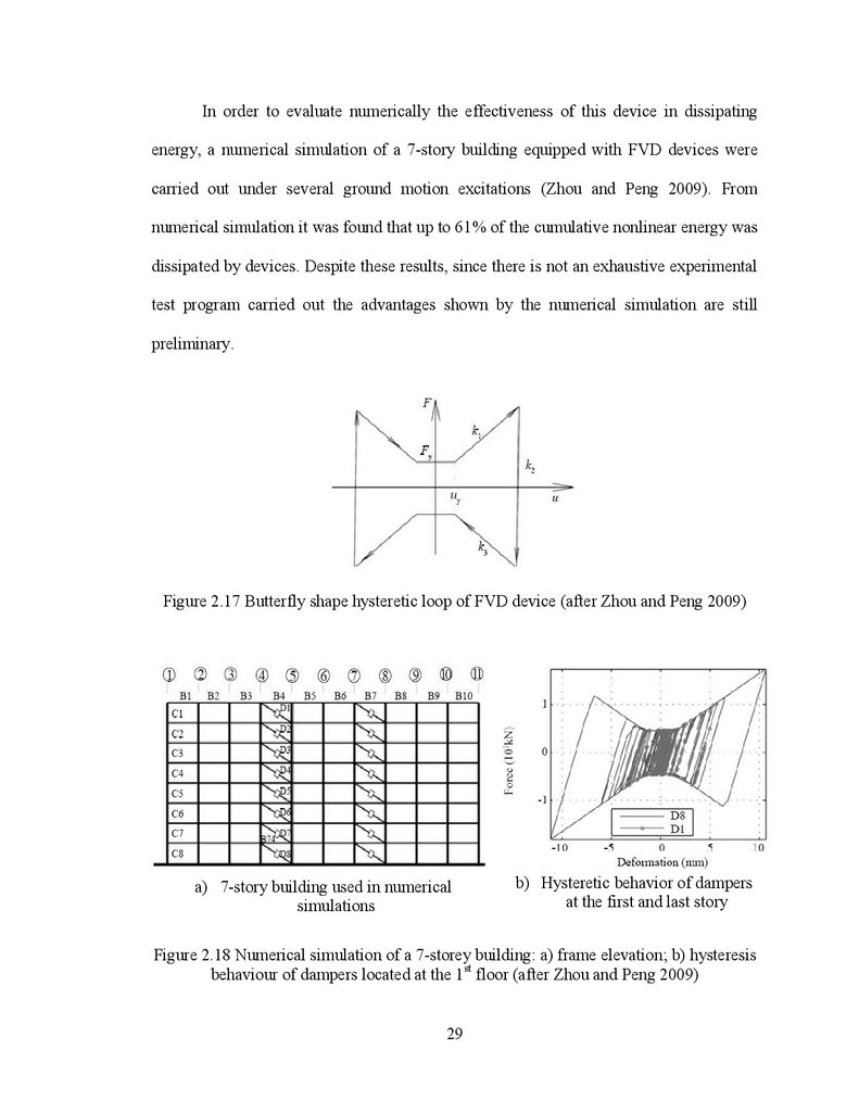
hysteresis behaviour follows a characteristic butterfly shape as shown in Figure 2.17
a) EDR damper
b) Hysteresis rule
c) Double flag shape
d) Rectangular shape
Figure 2.15 The EDR device and different hysteresis behaviour: a) sample; b) hysteresis
rule; c) double flag shape and d) rectangular shape (after Nims et al. 1993)
Figure 2.16 Friction variable damper, FVD (after Zhou and Peng 2009)
28
29.
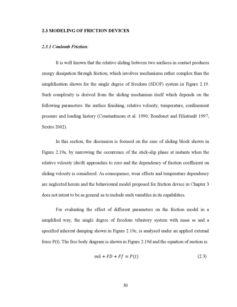
In order to evaluate numerically the effectiveness of this device in dissipatingenergy, a numerical simulation of a 7-story building equipped with FVD devices were
carried out under several ground motion excitations (Zhou and Peng 2009). From
numerical simulation it was found that up to 61% of the cumulative nonlinear energy was
dissipated by devices. Despite these results, since there is not an exhaustive experimental
test program carried out the advantages shown by the numerical simulation are still
preliminary.
Figure 2.17 Butterfly shape hysteretic loop of FVD device (after Zhou and Peng 2009)
a) 7-story building used in numerical
simulations
b) Hysteretic behavior of dampers
at the first and last story
Figure 2.18 Numerical simulation of a 7-storey building: a) frame elevation; b) hysteresis
behaviour of dampers located at the 1st floor (after Zhou and Peng 2009)
29
30.
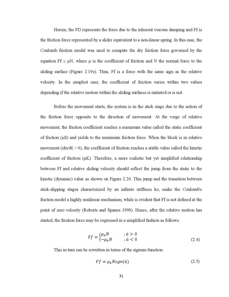
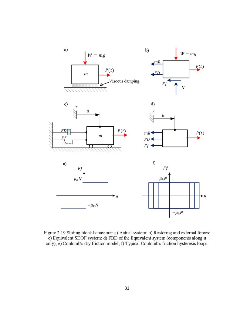
2.3 MODELING OF FRICTION DEVICES2.3.1 Coulomb Friction:
It is well known that the relative sliding between two surfaces in contact produces
energy dissipation through friction, which involves mechanisms rather complex than the
simplification shown for the single degree of freedom (SDOF) system in Figure 2.19.
Such complexity is derived from the sliding mechanism itself which depends on the
following parameters: the surface finishing, relative velocity, temperature, confinement
pressure and loading history (Constantineau et al. 1990; Bondonet and Filiatrault 1997;
Sextro 2002).
In this section, the discussion is focused on the case of sliding block shown in
Figure 2.19a, by narrowing the occurrence of the stick-slip phase at instants when the
relative velocity |du/dt| approaches to zero and the dependency of friction coefficient on
sliding velocity is considered. As consequence, wear effects and temperature dependency
are neglected herein and the behavioural model proposed for friction device in Chapter 3
does not intent to be as general as to include such variables in its capabilities.
For evaluating the effect of different parameters on the friction model in a
simplified way, the single degree of freedom vibratory system with mass m and a
specified inherent damping shown in Figure 2.19c, is analysed under an applied external
force P(t). The free body diagram is shown in Figure 2.19d and the equation of motion is:
(2.3)
30
31.
Herein, the FD represents the force due to the inherent viscous damping and Ff isthe friction force represented by a slider equivalent to a non-linear spring. In this case, the
Coulomb friction model was used to compute the dry friction force governed by the
equation Ff μN, where μ is the coefficient of friction and N the normal force to the
sliding surface (Figure 2.19e). Thus, Ff is a force with the same sign as the relative
velocity. In the simplest case, the coefficient of friction varies within two values
depending if the relative motion within the sliding surfaces is initiated or is not.
Before the movement starts, the system is in the stick stage due to the action of
the friction force opposite to the direction of movement. At the verge of relative
movement, the friction coefficient reaches a maximum value called the static coefficient
of friction (μS) and yields to the maximum friction force. When the block is in relative
movement (|du/dt| > 0), the coefficient of friction reaches a stable value called the kinetic
coefficient of friction (μK). Therefore, a more realistic but yet simplified relationship
between Ff and relative sliding velocity should reflect the jump from the static to the
kinetic (dynamic) value as shown on Figure 2.20. This jump and the transition between
stick-slipping stages characterized by an infinite stiffness ko, make the Coulomb's
friction model a highly nonlinear mechanism, while is evident that Ff is not defined at the
point of zero velocity (Roberts and Spanos 1990). Hence, after the relative motion has
started, the friction force may be expressed in a simplified fashion as follows:
(2.4)
This in turn can be rewritten in terms of the signum function:
(2.5)
31
32.
a)b)
Viscous damping
c)
d)
e)
f)
Figure 2.19 Sliding block behaviour: a) Actual system: b) Restoring and external forces;
c) Equivalent SDOF system; d) FBD of the Equivalent system (components along u
only); e) Coulomb's dry friction model; f) Typical Coulomb's friction hysteresis loops.
32
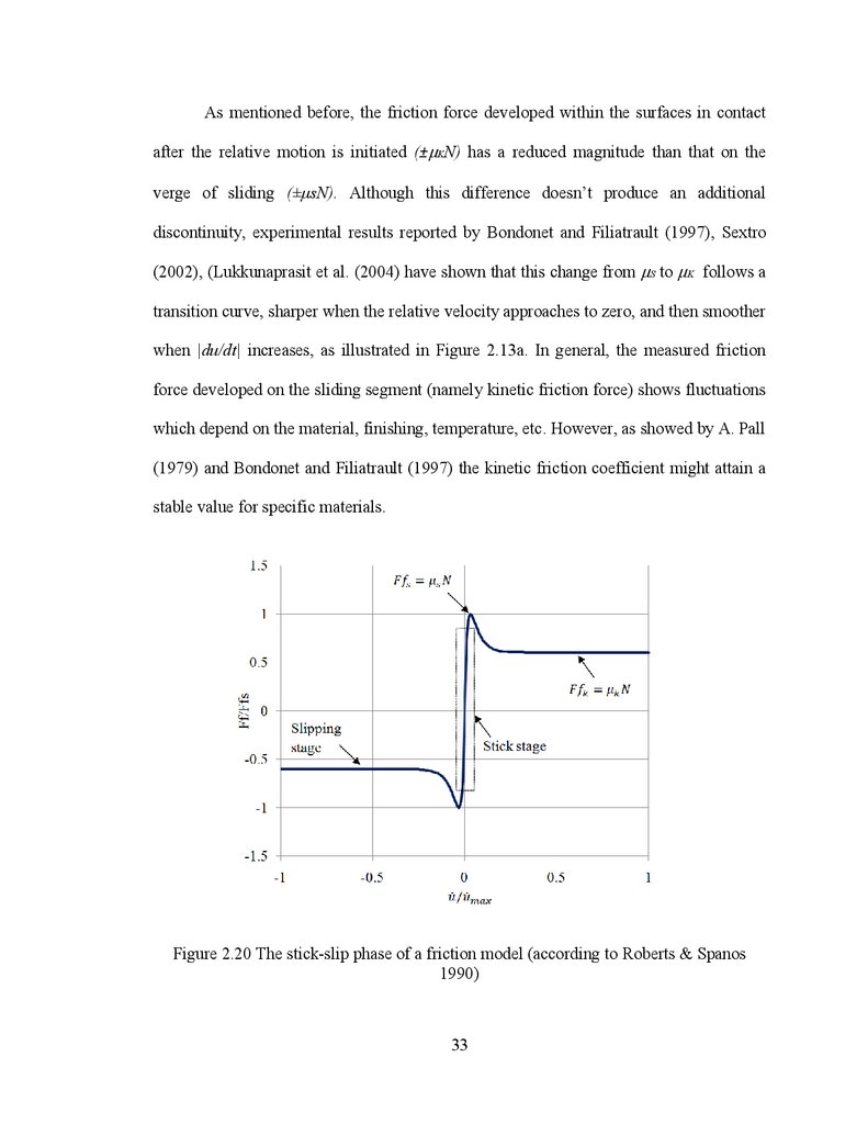
33.
As mentioned before, the friction force developed within the surfaces in contactafter the relative motion is initiated (±μKN) has a reduced magnitude than that on the
verge of sliding (± sN). Although this difference doesn‟t produce an additional
discontinuity, experimental results reported by Bondonet and Filiatrault (1997), Sextro
(2002), (Lukkunaprasit et al. (2004) have shown that this change from μS to μK follows a
transition curve, sharper when the relative velocity approaches to zero, and then smoother
when |du/dt| increases, as illustrated in Figure 2.13a. In general, the measured friction
force developed on the sliding segment (namely kinetic friction force) shows fluctuations
which depend on the material, finishing, temperature, etc. However, as showed by A. Pall
(1979) and Bondonet and Filiatrault (1997) the kinetic friction coefficient might attain a
stable value for specific materials.
Figure 2.20 The stick-slip phase of a friction model (according to Roberts & Spanos
1990)
33
34.
Accordingly, a more realistic friction model might be defined by a smooth function ableto approximate the transition between the stick-slip stages shown in Figure 2.20.
An alternative is to replace the signum function in Equation (2.5) by other, whose
derivatives are specially defined at the point of zero relative velocity in order to account
for the stick-slip transition stage. For instance, Figure 2.21 shows the models proposed by
Sextro (2002) and Makkar et al. (2005), where they used the (2/π)arctan(.) and the
tanh(.) functions
to smooth the transition between stick-slip and slip stages. For
considering the decay from the static to kinetic coefficient of friction, the exp(.) and the
tanh(.) functions are introduced by Sextro (2002) in Equation (2.6) and Makkar et al.
(2005) in Equation (2.7) as shown below:
(2.6)
where λe controls the decay of the difference between μS and μK, while kS defines the
sharpness of the slope for fitting the signum function.
(2.7)
Accordingly to Makkar et al. proposal, the first part of Eq. (2.7) controls the transition
between μS and μK, while the second part (last term) defines the behavior during the
slipping stage after the first part vanished, hence μK ≈ γ4. Parameters γ2, γ3 and γ5 define
the slope of the hyperbolic function.
34
35.
1.51
Ff/Ffmax
0.5
0
-0.5
Equation (2.6)
-1
Equation (2.7)
-1.5
-1
-0.5
0
0.5
1
Normalized relative velocity
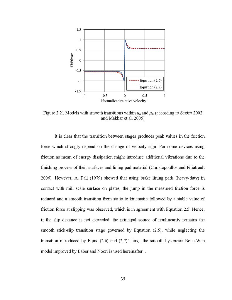
Figure 2.21 Models with smooth transitions within S and
and Makkar et al. 2005)
K (according to Sextro 2002
It is clear that the transition between stages produces peak values in the friction
force which strongly depend on the change of velocity sign. For some devices using
friction as mean of energy dissipation might introduce additional vibrations due to the
finishing process of their surfaces and lining pad material (Christopoullos and Filiatrault
2006). However, A. Pall (1979) showed that using brake lining pads (heavy-duty) in
contact with mill scale surface on plates, the jump in the measured friction force is
reduced and a smooth transition from static to kinematic followed by a stable value of
friction force at slipping was observed, which is in agreement with Equation 2.5. Hence,
if the slip distance is not exceeded, the principal source of nonlinearity remains the
smooth stick-slip transition stage governed by Equation (2.5), while neglecting the
transition introduced by Eqns. (2.6) and (2.7).Thus, the smooth hysteresis Bouc-Wen
model improved by Baber and Noori is used hereinafter...
35
36.
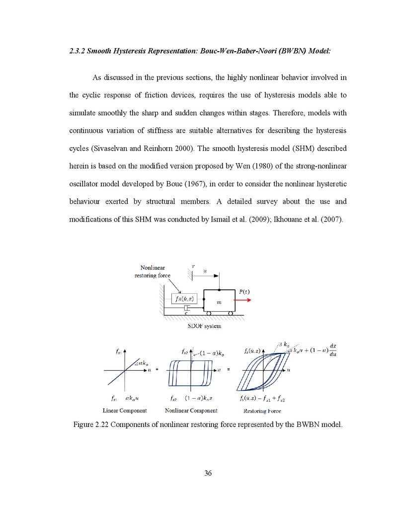
2.3.2 Smooth Hysteresis Representation: Bouc-Wen-Baber-Noori (BWBN) Model:As discussed in the previous sections, the highly nonlinear behavior involved in
the cyclic response of friction devices, requires the use of hysteresis models able to
simulate smoothly the sharp and sudden changes within stages. Therefore, models with
continuous variation of stiffness are suitable alternatives for describing the hysteresis
cycles (Sivaselvan and Reinhorn 2000). The smooth hysteresis model (SHM) described
herein is based on the modified version proposed by Wen (1980) of the strong-nonlinear
oscillator model developed by Bouc (1967), in order to consider the nonlinear hysteretic
behaviour exerted by structural members. A detailed survey about the use and
modifications of this SHM was conducted by Ismail et al. (2009); Ikhouane et al. (2007).
Figure 2.22 Components of nonlinear restoring force represented by the BWBN model.
36
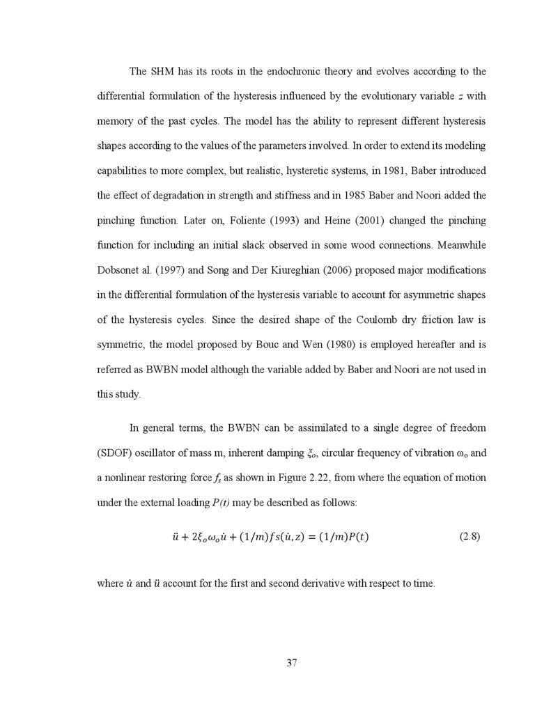
37.
The SHM has its roots in the endochronic theory and evolves according to thedifferential formulation of the hysteresis influenced by the evolutionary variable z with
memory of the past cycles. The model has the ability to represent different hysteresis
shapes according to the values of the parameters involved. In order to extend its modeling
capabilities to more complex, but realistic, hysteretic systems, in 1981, Baber introduced
the effect of degradation in strength and stiffness and in 1985 Baber and Noori added the
pinching function. Later on, Foliente (1993) and Heine (2001) changed the pinching
function for including an initial slack observed in some wood connections. Meanwhile
Dobsonet al. (1997) and Song and Der Kiureghian (2006) proposed major modifications
in the differential formulation of the hysteresis variable to account for asymmetric shapes
of the hysteresis cycles. Since the desired shape of the Coulomb dry friction law is
symmetric, the model proposed by Bouc and Wen (1980) is employed hereafter and is
referred as BWBN model although the variable added by Baber and Noori are not used in
this study.
In general terms, the BWBN can be assimilated to a single degree of freedom
(SDOF) oscillator of mass m, inherent damping
o, circular frequency of vibration ωo and
a nonlinear restoring force fs as shown in Figure 2.22, from where the equation of motion
under the external loading P(t) may be described as follows:
(2.8)
where
and
account for the first and second derivative with respect to time.
37
38.
The nonlinear restoring force fs defines the hysteretic behavior of the SDOFsystem and has two components: the first one is the linear part representing the
participation level of the initial stiffness into the inelastic response of the oscillator,
whereas the later accounts on the nonlinear hysteretic characteristic with memory of
previous loading cycles by means of the evolutionary variable z. Hence, the restoring
force fs can be written as:
(2.9)
where α is the participation ratio of the initial stiffness in the nonlinear response, ko is the
initial stiffness of the system, u is the displacement of the SDOF system and z is the
hysteresis variable, evolving according to the nonlinear ordinary differential equation:
(2.10)
Thus, in equation (2.10),
and
are parameters controlling the shape of the hysteresis
cycle and the exponent n influences the sharpness of the model in the transition zones.
Meanwhile h(z) is a function controlling the pinching (if required) of the hysteresis loops
and the remaining parameters A,
and
control the degradation process in stiffness and
strength. Depending upon the memory of past cycles, i.e. the hysteretic energy
accumulated up to the actual time, the degradation process is introduced into the
hysteretic response by the following expressions:
(2.11)
38
39.
(2.12)(2.13)
Therefore equation (2.11) induces both strength and stiffness degradation whilst equation
(2.12) influences the strength and equation (2.13) the stiffness degradation process. The
term (t) is the hysteretic energy up to the specified time tf, defined by (Foliente 1993):
(2.14)
If ε(t) is written in rate form it becomes:
(2.15)
On the other hand, the pinching process is controlled by function given in Equation (2.16)
where 1 and 2 are parameters dependent on the energy dissipated and the desired drop in
the slope. A detailed explanation may be found in literature (Foliente 1993).
(2.16)
The case of no pinching effects, neither stiffness nor strength degradation in the
hysteretic behavior is defined by setting up the terms
A,
,
, and
1 equal to zero.
Thus, equations (2.11) to (2.13) and equation (2.16) are simplified as follows:
(2.17)
(2.18)
(2.19)
39
40.
(2.20)Based on experimental data reported for friction devices, in this work it is assumed that
no degradation or pinching effects are presented during the slipping stage. Although
Lukkunaprasit et al. (2004) has shown that in case of bolt impact there is a reduction in
the slip load for the following cycles, this issue is outside the scope of this thesis.
Therefore, the friction force is simulated by the BWBN model defined by the set
of Equations (2.9), (2.10) and (2.17) to (2.20). Through the survey made in this chapter
concerning the practical application and behaviour of friction dampers incorporated in
building structures (the EDR device is excepted), it is concluded that an accurate nonlinear behavior of these devices could be simulated when all stages encountered during
the cyclic loading (stick-slip, slipping and slip-lock) are considered.
40