
 Construction
Similar presentations:


")


Review of steel buckling-restrained braces
1.
ArticlesGaetano Della Corte
Mario D’Aniello
Raffaele Landolfo*
Federico M. Mazzolani
DOI: 10.1002/stco.201110012
Review of steel buckling-restrained braces
Buckling-restrained braces (BRBs) are a relatively recent development in the field of
seismic-resistant steel structures. Their distinctive feature is the non-buckling behaviour
typically achieved by encasing a steel core in a concrete-filled tube, but alternatives
have been proposed. Restraining the brace from buckling enhances ductility significantly
and allows a symmetric response under tension or compression forces. The design of
BRB frames must consider a number of specific issues that are currently not covered by
European standards and regulations. This paper presents a brief summary of the most
recent research results and attempts to summarize the basic design issues as they emerge
from both research and the codification rules of non-European Countries. Conclusions
are drawn regarding future research required to address the development of design
rules in Europe, too.
1 Introduction
Steel braces have long been used for
both wind- and seismic-resistant structures. In the seismic field of application, repeated buckling in compression is the source of strength and
stiffness degradation. A relatively recent development is the “buckling-restrained brace” (BRB), which is a special type of brace with global buckling inhibited by an appropriate system. The avoidance of global buckling
implies a compression force displacement behaviour very similar to the response exhibited under tension forces.
According to Xie [1], the earliest documented proposal to inhibit brace
buckling was formulated by Wakabayashi et al. [2], who developed a
pioneering system with a flat steel
plate sandwiched between a pair of
precast reinforced concrete panels. A
few years later, Kimura et al. [3] presented a study on the first form of
BRB employing a modern type of
buckling-restraint system: a conventional brace was encased in a square
steel pipe filled with mortar. In these
first attempts, a void was left between
* Corresponding author:
e-mail [email protected]
the steel brace and the mortar filling
in order to allow relative movement,
but this void also resulted in local
buckling detrimental to the hysteretic
performance. Mochizuki et al. [4] conducted tests on similar braces, using a
concrete casing and an interface layer
made from a shock-absorbing material in order to avoid adhesion between the steel and the concrete and
to permit transverse expansion of the
cross-section in compression. The layer
of “unbonding” material at the steelconcrete interface gave rise to the term
“unbonded” brace, which has subsequently been used to identify this
kind of BRB. Since that time, many
studies have been carried out on “unbonded” braces [5]–[17], the objectives
and results of which are described
below. The concrete-filled bucklingrestraint system may be found to be
expensive because of the concrete
pouring and curing phases, although
a relatively cheap “unbonded” BRB
has recently been proposed and tested
[19]. As an alternative, “all-steel” buckling-restraint systems have been developed [20]–[28], where the steel core
is typically separated from the steel
buckling-restraint unit by a small void.
Hybrid “unbonded all-steel” BRBs
have also been investigated [21]. “Allsteel” BRBs can also be demountable
if bolted connections are used, thus
permitting inspection and monitoring.
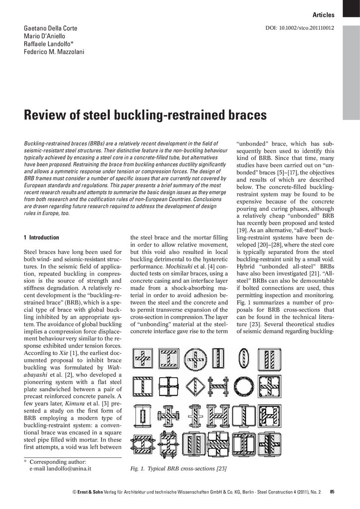
Fig. 1 summarizes a number of proposals for BRB cross-sections that
can be found in the technical literature [23]. Several theoretical studies
of seismic demand regarding buckling-
Fig. 1. Typical BRB cross-sections [23]
© Ernst & Sohn Verlag für Architektur und technische Wissenschaften GmbH & Co. KG, Berlin · Steel Construction 4 (2011), No. 2
85
2.
G. Della Corte/M. D‘Aniello/R. Landolfo/F. M. Mazzolani · Review of steel buckling-restrained bracesrestrained braced frames (BRBFs)
[29]–[33] as well as finite element
modelling of BRBs have also been
carried out [34], [35].
This paper presents a short review
of a few basic issues in the analysis
and design of BRBFs and attempts to
emphasize those aspects that deserve
particular attention and further research in view of the need to develop
European design guidelines addressing
this relatively new structural typology.
The material presented is not considered to be exhaustive, but rather highlights a few of the important issues.
For an easier reading of this
paper, the glossary proposed by the
“NEHRP Recommended Provisions
for Seismic Regulations for New Buildings and other Structures” [36] has
been adopted. A summary of the main
definitions is given below for the convenience of the reader:
– Buckling-restrained braced frame:
“A diagonally braced frame … in
which all members of the bracing
system are subject primarily to axial
forces and in which the limit state
of compression buckling of braces
must be precluded at forces and
deformations corresponding to 1.5
times the Design Storey Drift.”
– Buckling-restraining system: “A system of restraints that limits buckling of the steel core in BRBF. …”
– Steel core: “The axial force-resisting element of braces in BRBF. The
steel core contains a yielding segment and connections to transfer
its axial force to adjoining elements; it may also contain projections beyond the casing and transition segments between the projections and yielding segment.”
– Casing: “An element that resists
forces transverse to the axis of the
brace, thereby restraining buckling
of the core. … The casing resists
little or no force in the axis of the
brace.”
Fig. 2 shows the various parts constituting a BRB in schematic form.
2 Research into BRB components and
systems
2.1 General issues
Research studies concerning BRB
components, subassemblies and fullscale structures can be subdivided
into a) experimental and b) theore-
86
Steel Construction 4 (2011), No. 2
Fig. 2. Parts constituting a typical BRB
tical treatments. Within each of the
two general topics, several subtopics
could be identified, for example:
a) Experimental tests:
a1) Required casing stiffness: This
subtopic includes investigations
into the minimum casing stiffness required. The intensity and
distribution of forces transferred
from the steel core to the casing
is obviously part of this subtopic.
a2) Deformation capacity and lowcycle fatigue: This subtopic involves the characterization of the
ductility capacity for various cyclic loading histories.
a3) Connections: This subtopic involves the characterization of how
the strength and flexibility of connections between braces and adjoining frame members may influence the seismic performance
of the whole system.
a4) Influence of unbonding layer or
void: This subtopic involves studying how different types of interfaces between steel core and
casing may influence the brace
performance.
b) Numerical studies:
b1) Seismic performance of frames
equipped with BRBs: This subtopic includes numerical studies of
the overall seismic performance of
frames with BRBs. One basic objective is to evaluate statistically
the ductility and energy dissipation demand for BRBs as well as
the force demands for non-dissipative members and connections.
b2) Finite element models of BRBs:
This subtopic involves the development of finite element models
reproducing the behaviour observed experimentally.
A short description of the research
carried out for each of the previous
subtopics is given in the following,
trying to place an emphasis on the
most important and recent results.
2.2 Experimental tests
2.2.1 Required casing stiffness
The casing must possess adequate
stiffness to keep the steel core in a
stable axial configuration. The parameter used to quantify the stiffness
required is the ratio between the Euler
buckling axial load PE of the casing
and the actual yield force Py of the internal steel core.
Watanabe et al. [7] systematically
studied the influence of the PE/Py
ratio using “unbonded” BRBs. They
suggest using a PE/Py ratio equal to
1.5 at least. Iwata and Murai [17] also
performed tests on “unbonded” BRBs
and suggest a linear relationship between the cumulative plastic strain
(energy dissipation) capacity and the
PE/Py ratio.
Xie [1] reports on experimental
tests carried out in Japan [5] aimed
at measuring directly the restraining
forces and bending moments that may
develop in the restraining system. Although the tests were carried out with
reference to a buckling-restraint system constituted by reinforced concrete
panels, the general concepts may be
applicable to more common forms of
BRB. Test results show that the distribution of bending moments is similar
to that of the initial brace deflection
and that the equivalent uniformly distributed transverse load producing
the same maximum moment is equal
to about 1.5 % of the yielding axial
force.
3.
G. Della Corte/M. D‘Aniello/R. Landolfo/F. M. Mazzolani · Review of steel buckling-restrained braces2.2.2 Deformation capacity and
low cycle fatigue
Experimental tests e.g. [11], [12], [13]
have shown that the cumulative ductility capacity (sum of plastic deformations plus yield deformation over yield
deformation (σδp,i + δy)/δy) of typical
“unbonded” BRBs can be very large,
up to average values of about 1000
when the maximum ductility demand
(peak total deformation over yield deformation δmax/δy) is not greater than
15. Apart from the value of the PE/Py
ratio (section 2.2.1), the deformation
and energy dissipation capacity of
BRBs also depend on the detailing of
the casing and its interface with the
steel core. In the case of “unbonded”
BRBs, the interface material layer is
normally able to permit effectively the
transverse expansion of the yielding
core in compression and also to control local buckling of the core. Besides,
the casing is normally stiff and strong
enough to resist the forces transferred
by the core to the casing at the interface. Looked at in this way, the detailing of “all-steel” BRBs may be more
delicate because a void is typically
left between the core and the casing
and this makes the core more prone
to local buckling. This aspect is further discussed in section 2.2.4.
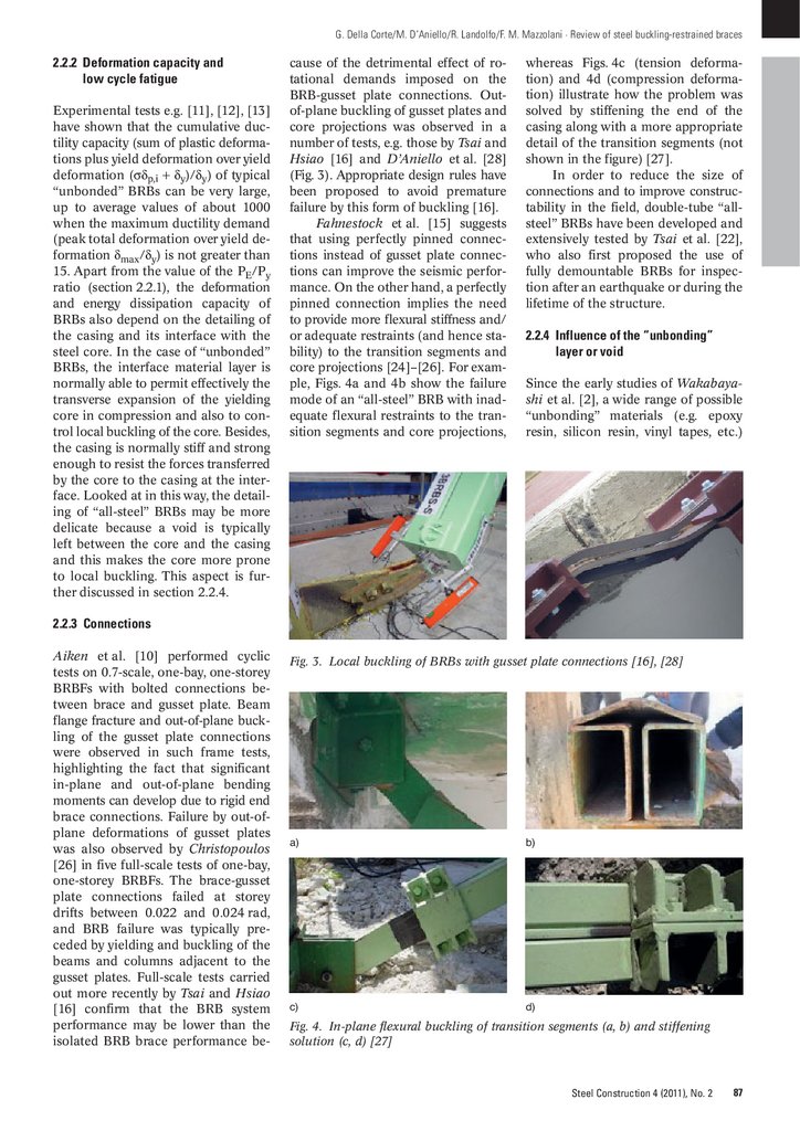
cause of the detrimental effect of rotational demands imposed on the
BRB-gusset plate connections. Outof-plane buckling of gusset plates and
core projections was observed in a
number of tests, e.g. those by Tsai and
Hsiao [16] and D’Aniello et al. [28]
(Fig. 3). Appropriate design rules have
been proposed to avoid premature
failure by this form of buckling [16].
Fahnestock et al. [15] suggests
that using perfectly pinned connections instead of gusset plate connections can improve the seismic performance. On the other hand, a perfectly
pinned connection implies the need
to provide more flexural stiffness and/
or adequate restraints (and hence stability) to the transition segments and
core projections [24]–[26]. For example, Figs. 4a and 4b show the failure
mode of an “all-steel” BRB with inadequate flexural restraints to the transition segments and core projections,
whereas Figs. 4c (tension deformation) and 4d (compression deformation) illustrate how the problem was
solved by stiffening the end of the
casing along with a more appropriate
detail of the transition segments (not
shown in the figure) [27].
In order to reduce the size of
connections and to improve constructability in the field, double-tube “allsteel” BRBs have been developed and
extensively tested by Tsai et al. [22],
who also first proposed the use of
fully demountable BRBs for inspection after an earthquake or during the
lifetime of the structure.
2.2.4 Influence of the “unbonding”
layer or void
Since the early studies of Wakabayashi et al. [2], a wide range of possible
“unbonding” materials (e.g. epoxy
resin, silicon resin, vinyl tapes, etc.)
2.2.3 Connections
Aiken et al. [10] performed cyclic
tests on 0.7-scale, one-bay, one-storey
BRBFs with bolted connections between brace and gusset plate. Beam
flange fracture and out-of-plane buckling of the gusset plate connections
were observed in such frame tests,
highlighting the fact that significant
in-plane and out-of-plane bending
moments can develop due to rigid end
brace connections. Failure by out-ofplane deformations of gusset plates
was also observed by Christopoulos
[26] in five full-scale tests of one-bay,
one-storey BRBFs. The brace-gusset
plate connections failed at storey
drifts between 0.022 and 0.024 rad,
and BRB failure was typically preceded by yielding and buckling of the
beams and columns adjacent to the
gusset plates. Full-scale tests carried
out more recently by Tsai and Hsiao
[16] confirm that the BRB system
performance may be lower than the
isolated BRB brace performance be-
Fig. 3. Local buckling of BRBs with gusset plate connections [16], [28]
a)
b)
c)
d)
Fig. 4. In-plane flexural buckling of transition segments (a, b) and stiffening
solution (c, d) [27]
Steel Construction 4 (2011), No. 2
87
4.
G. Della Corte/M. D‘Aniello/R. Landolfo/F. M. Mazzolani · Review of steel buckling-restrained braceshave been studied. The thickness of
the “unbonding” layer typically varies
between 0.15 and 2 mm depending on
the material. The “unbonding” layer
must be sufficiently soft to permit the
transverse expansion of the yielding
steel core, thus resulting in an adequately symmetric tension-compression response. Several tests on specimens employing different “unbonding” layer materials and thicknesses
were carried out by Tsai et al. [22],
which revealed the percentage difference between compression and tension resistance as a function of the
type of “unbonding” material and the
intensity of the average axial deformation. The compressive strength may
be up to 35 % greater than the tensile
strength at average axial strains of
2.5 %.
Contrary to “unbonded” braces,
in “all-steel” devices a void is typically
included between core and casing in
order to allow relative core-casing deformations. The gap size may vary
from 0.7 to 3.5 mm depending on the
type of BRB [22]. Iwata et al. [20]
tested both typical “all-steel” BRBs
and those with an “unbonding” layer.
The nominal clearance was equal to
1 mm per core side, whereas the “unbonded all-steel” BRBs had a 1 mm
thick “unbonding” material layer. Their
tests showed that specimens without
the “unbonding” layer failed because
of core fracture caused by plastic strain
concentration due to core local buckling. The “all-steel” specimens with
the “unbonding” material layer experienced a better response without
strain localization.
Tests comparing the performance
of “unbonded” and “all-steel” BRBs
have also been carried out by Tremblay et al. [24], who emphasize the
need to control the local core buckling in order to minimize friction forces
and develop uniform strain in the
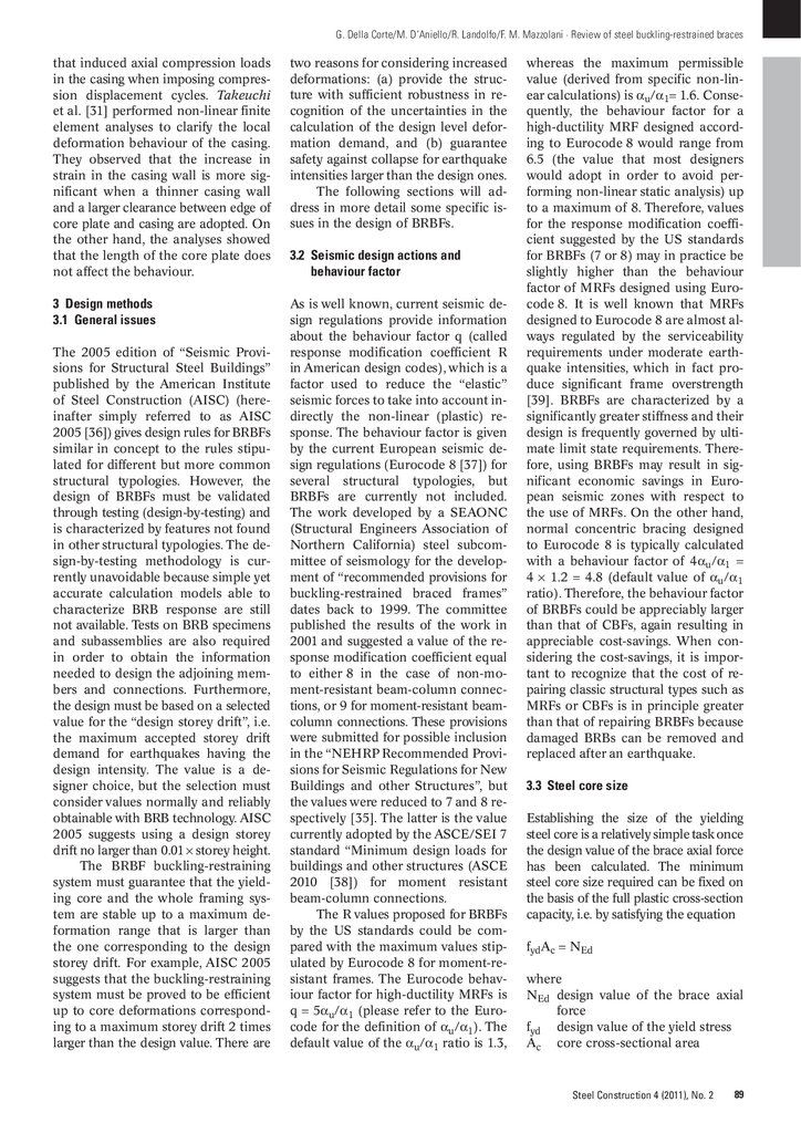
core. Tests carried out by D’Aniello
et al. [27] and Della Corte et al. [28]
on special “all-steel” BRBs specifically
developed for seismic upgrading of
reinforced concrete frames with masonry infill panels (Fig. 5) have shown
that, in the worst case and notwithstanding the localization of plastic
strain (Fig. 6), BRBs achieved a cumulative ductility capacity equal to
235, which may still be larger than the
likely demand from earthquakes [27],
[28].
88
Steel Construction 4 (2011), No. 2
Fig. 5. Full-scale tests on BRBs for seismic upgrading [27], [28]
Fig. 6. Local buckling and plastic strain localization in the core [27], [28]
2.3 Numerical studies
2.3.1 Seismic performance of frames
equipped with BRBs
Over the last decade, a few theoretical
studies have been addressed to evaluate the seismic performance of steel
buildings equipped with BRBs. The
studies by Clark et al. [9] and Sabelli
et al. [29] showed that BRBFs may be
prone to (1) relatively large residual
drifts and (2) a concentration of plastic deformation demand at one or a
few storeys. These shortcomings are
clearly a result of the low post-yield
stiffness of BRBs. In order to reduce
residual drifts, Kiggins and Uang [30]
propose designing dual systems comprising BRBFs and moment-resistant
frames (MRFs), which provide some
post-yield stiffness (hence re-centring
capacity). Ariyaratana and Fahnestock
[34] also investigated the performance
of dual systems, concluding that using
MRFs acting in parallel with BRBFs
is an effective way of reducing residual drifts.
Another important aspect addressed via numerical simulation has
been the evaluation of the maximum
expected ductility demand for braces.
Fahnestock et al. [28] computed maximum values of ductility demand up to
26 under six ground motions scaled
to the maximum expected design intensity (i.e. 1.5 times larger than the
design level intensity). According to
the same authors, the cumulative brace
ductility demand reached a maximum
value of 99 and 171 under the design
and the maximum expected earthquake intensity respectively. Considering the experimental results available and using a quite conservative
value for cumulative ductility capacity of 400 (for well-designed, wellconstructed BRBs), the demand/capacity ratio is so small (171/400 =
0.43) that it suggests that seismic design of BRBs is not governed by lowcycle fatigue phenomena.
Recent numerical studies were
also addressed to analyse the response
of tall buildings equipped with BRBs.
Kim et al. [32] studied the response
of framed and braced tubular tall
buildings (from 36 to 72 storeys) and
showed how the use of BRBFs may
result in a good compromise between
stiffness/strength and ductility.
2.3.2 Finite element models for BRBs
Korzekwa and Tremblay [33] performed a non-linear finite element
analysis to reproduce the response of
“all-steel” BRBs tested under cyclic
loading. The analysis permitted the
description of the complex interaction
that develops between brace core and
casing. In particular, the contact forces
were found to be resisted in flexure
by the casing, and in tension by the
bolts holding together the casing components. The contact forces also resulted in longitudinal frictional forces
5.
G. Della Corte/M. D‘Aniello/R. Landolfo/F. M. Mazzolani · Review of steel buckling-restrained bracesthat induced axial compression loads
in the casing when imposing compression displacement cycles. Takeuchi
et al. [31] performed non-linear finite
element analyses to clarify the local
deformation behaviour of the casing.
They observed that the increase in
strain in the casing wall is more significant when a thinner casing wall
and a larger clearance between edge of
core plate and casing are adopted. On
the other hand, the analyses showed
that the length of the core plate does
not affect the behaviour.
two reasons for considering increased
deformations: (a) provide the structure with sufficient robustness in recognition of the uncertainties in the
calculation of the design level deformation demand, and (b) guarantee
safety against collapse for earthquake
intensities larger than the design ones.
The following sections will address in more detail some specific issues in the design of BRBFs.
3 Design methods
3.1 General issues
As is well known, current seismic design regulations provide information
about the behaviour factor q (called
response modification coefficient R
in American design codes), which is a
factor used to reduce the “elastic”
seismic forces to take into account indirectly the non-linear (plastic) response. The behaviour factor is given
by the current European seismic design regulations (Eurocode 8 [37]) for
several structural typologies, but
BRBFs are currently not included.
The work developed by a SEAONC
(Structural Engineers Association of
Northern California) steel subcommittee of seismology for the development of “recommended provisions for
buckling-restrained braced frames”
dates back to 1999. The committee
published the results of the work in
2001 and suggested a value of the response modification coefficient equal
to either 8 in the case of non-moment-resistant beam-column connections, or 9 for moment-resistant beamcolumn connections. These provisions
were submitted for possible inclusion
in the “NEHRP Recommended Provisions for Seismic Regulations for New
Buildings and other Structures”, but
the values were reduced to 7 and 8 respectively [35]. The latter is the value
currently adopted by the ASCE/SEI 7
standard “Minimum design loads for
buildings and other structures (ASCE
2010 [38]) for moment resistant
beam-column connections.
The R values proposed for BRBFs
by the US standards could be compared with the maximum values stipulated by Eurocode 8 for moment-resistant frames. The Eurocode behaviour factor for high-ductility MRFs is
q = 5αu/α1 (please refer to the Eurocode for the definition of αu/α1). The
default value of the αu/α1 ratio is 1.3,
The 2005 edition of “Seismic Provisions for Structural Steel Buildings”
published by the American Institute
of Steel Construction (AISC) (hereinafter simply referred to as AISC
2005 [36]) gives design rules for BRBFs
similar in concept to the rules stipulated for different but more common
structural typologies. However, the
design of BRBFs must be validated
through testing (design-by-testing) and
is characterized by features not found
in other structural typologies. The design-by-testing methodology is currently unavoidable because simple yet
accurate calculation models able to
characterize BRB response are still
not available. Tests on BRB specimens
and subassemblies are also required
in order to obtain the information
needed to design the adjoining members and connections. Furthermore,
the design must be based on a selected
value for the “design storey drift”, i.e.
the maximum accepted storey drift
demand for earthquakes having the
design intensity. The value is a designer choice, but the selection must
consider values normally and reliably
obtainable with BRB technology. AISC
2005 suggests using a design storey
drift no larger than 0.01 × storey height.
The BRBF buckling-restraining
system must guarantee that the yielding core and the whole framing system are stable up to a maximum deformation range that is larger than
the one corresponding to the design
storey drift. For example, AISC 2005
suggests that the buckling-restraining
system must be proved to be efficient
up to core deformations corresponding to a maximum storey drift 2 times
larger than the design value. There are
3.2 Seismic design actions and
behaviour factor
whereas the maximum permissible
value (derived from specific non-linear calculations) is αu/α1= 1.6. Consequently, the behaviour factor for a
high-ductility MRF designed according to Eurocode 8 would range from
6.5 (the value that most designers
would adopt in order to avoid performing non-linear static analysis) up
to a maximum of 8. Therefore, values
for the response modification coefficient suggested by the US standards
for BRBFs (7 or 8) may in practice be
slightly higher than the behaviour
factor of MRFs designed using Eurocode 8. It is well known that MRFs
designed to Eurocode 8 are almost always regulated by the serviceability
requirements under moderate earthquake intensities, which in fact produce significant frame overstrength
[39]. BRBFs are characterized by a
significantly greater stiffness and their
design is frequently governed by ultimate limit state requirements. Therefore, using BRBFs may result in significant economic savings in European seismic zones with respect to
the use of MRFs. On the other hand,
normal concentric bracing designed
to Eurocode 8 is typically calculated
with a behaviour factor of 4αu/α1 =
4 × 1.2 = 4.8 (default value of αu/α1
ratio). Therefore, the behaviour factor
of BRBFs could be appreciably larger
than that of CBFs, again resulting in
appreciable cost-savings. When considering the cost-savings, it is important to recognize that the cost of repairing classic structural types such as
MRFs or CBFs is in principle greater
than that of repairing BRBFs because
damaged BRBs can be removed and
replaced after an earthquake.
3.3 Steel core size
Establishing the size of the yielding
steel core is a relatively simple task once
the design value of the brace axial force
has been calculated. The minimum
steel core size required can be fixed on
the basis of the full plastic cross-section
capacity, i.e. by satisfying the equation
fydAc = NEd
where
NEd design value of the brace axial
force
fyd design value of the yield stress
Ac core cross-sectional area
Steel Construction 4 (2011), No. 2
89
6.
G. Della Corte/M. D‘Aniello/R. Landolfo/F. M. Mazzolani · Review of steel buckling-restrained bracesAccording to AISC 2005, the design
value of the yield stress can either be
a specified minimum yield stress or
the actual yield stress determined from
coupon tests.
In order to establish how the design axial force varies over the height,
the objective of a good seismic design
should be considered, i.e. engaging
every brace in the plastic range of
response [40]–[42]. Current codified
design rules, such as those of Eurocode 8, follow simplified approaches,
stipulating that for standard (buckling-permitted) braced frames the ratio Ωi = Npl,Rd,i/NEd,i, where N = axial
force in braces, should not vary by
more than 25 % from one storey to
another. This is known to be a severe
limitation to the design freedoms when
selecting the brace cross-section [43],
[44], leading to a brace strength significantly in excess of the minimum
required. In the case of BRBFs, the size
of the yielding core can be tailored
according to needs, thus achieving a
global strength very close to that required.
3.4 Casing
The design of the element (casing)
that directly restrains the steel core
against buckling is the most typical
task related to BRBF design. The first
fundamental step is to estimate the
maximum axial force that could be
transferred from the yielding steel
core. This may be significantly larger
than the full plastic cross-section
capacity because (1) material overstrength with respect to the design
yield strength (i.e. randomness of
yield strength of steel), (2) material
hardening, (3) friction forces developing between core and casing, and
(4) restrained transverse expansion
of the steel core cross-section (more
generally, restrained lateral deformations). The last two sources of overstrength have already been commented on in section 2.2.4.
According to AISC 2005, the peak
axial compressive force transferred by
the brace is expressed as
βωRyPysc
where
Ry ratio between average and specified minimum yield stress (used
in sizing the core, section 3.3);
90
Steel Construction 4 (2011), No. 2
ω
β
obviously Ry = 1 if the actual
yield stress is used to size the
core; in the Eurocode 8 format,
if the core is designed using the
characteristic yield stress fyk and
a partial safety factor γs = 1, coefficient Ry should be the ratio
between the average and characteristic values of the steel yield
stress (γRd).
strain hardening factor, determined from tests (section 3.6) as
the ratio of maximum tensile
strength to design yield strength
(Pysc in AISC symbolism); the
maximum tensile strength is measured experimentally for the range
of deformations corresponding to
twice the design storey drift.
ratio of maximum compressive to
maximum tensile force as measured experimentally (section 3.6)
for the range of deformations
corresponding to twice the design storey drift (see comments
in section 3.1).
3.5 Connections and adjoining elements
Brace connections as well as adjoining members are part of the bucklingrestraint system [36]. According to
AISC 2005, these structural components must be designed in order to
guarantee stability of the brace core
as well as the strength and stability of
connections and adjoining members
up to system forces and deformations
corresponding to twice the design
storey drift. AISC 2005 specifies that
connections and adjoining member
forces due to earthquake effects must
be calculated on the basis of the maximum compression and tension brace
strengths. This requirement clearly
corresponds to a “capacity design”
criterion. Capacity design in Eurocode 8 is currently performed by amplifying the design-level earthquake
effects using the coefficient 1.1γRdΩ
(for definitions of symbols see above).
The application of this method to
BRBFs could still be pursued, although
a direct consideration of the maximum
forces transferred by the braces, as
suggested by AISC 2005, might represent a simpler and clearer design method. An explicit calculation of the
maximum forces transferred by braces
would appear more rational because
(1) the peak forces should be determined based on experiments, and (2)
the core size can generally be well
tailored to the strength required (i.e.
it is more probable to have yielding of
every brace). On the contrary, for normal (buckling-permitted) braces, both
determining extreme values of forces
transferred from braces and assuring
all braces yielding would be quite difficult, which justifies the Eurocode
procedure.
3.6 Experimental verification of braces
Tests on BRB specimens and BRBF
subassemblies are required principally
for two reasons: (1) to evaluate the
peak compressive and tensile forces
transferred by the brace, and (2) to
evaluate the force and deformation
demand for end-brace and beamcolumn connections. AISC 2005 prescribes that at least two tests to be
performed, one on a subassembly able
to reproduce the real end-brace and
beam-column connection behaviour,
and the other on a simple brace specimen subjected to axial forces.
One important point in testing
for design is to establish the correct
loading procedure to be applied, i.e.
the number and amplitude of the deformation cycles to be imposed on
the specimen. Since the test must be
representative of the BRBF response
during real earthquakes, the loading
sequence should in principle be based
upon inelastic time-history analysis of
the BRBFs using a sufficiently large
number of representative ground motion time histories. Besides, the procedure requires setting the “design
storey drift” from the beginning, which
is a reference value for the maximum
storey drift that the structure should
undergo during earthquakes having
the design intensity. As commented on
in section 3.4, the BRBF must prove
to be stable up to a larger maximum
deformation range. AISC 2005 stipulates a value of twice the design storey
drift based on inelastic time-history
analysis results [28], [29].
The adoption of a design-by-testing procedure in the European codes,
similar to that implemented by AISC
2005, necessarily requires specific research to be carried out in order to
characterize the statistics of deformation demands on BRBFs and to establish consequently a reasonable but
conventional loading procedure for
design verification purposes.
7.
G. Della Corte/M. D‘Aniello/R. Landolfo/F. M. Mazzolani · Review of steel buckling-restrained braces3.7 Alternative design procedures
5 Conclusions
Design procedures other than the classical code-specified force-based method have often been proposed. Apart
from the methods based on mathematical optimization procedures, two
viable alternatives are worth mentioning: the “displacement-based” and the
“energy-based” design methods. Examples of developments of such procedures in the special case of BRBFs
are given in [40]–[42]. The advantage
of the new procedures is the possibility of having direct and better control
of the level of seismic damage (performance-based engineering).
Buckling-restrained braced frames
(BRBFs) are a very attractive seismicresistant structural system because of
the good ratio between seismic effectiveness and low to medium cost compared with other non-conventional
energy dissipation measures. The effectiveness is due to the relatively high
stiffness, compared with classical moment-resistant frames, and the large
energy dissipation capacity, compared
with classical concentrically braced
frames. One shortcoming of BRBFs is
the propensity to large residual displacements, which is indeed a characteristic behaviour of any elastic-plastic device. However, flexible MRFs
used in combination with BRBFs can
provide significant post-yield stiffness
and consequent re-centring capability.
4 Applications
Starting in the 1980s and 1990s, when
the first prototypes were developed and
commercialized by a Japanese company, BRBs have gained popularity
with a growing number of new buildings using BRBs as a primary lateral
force-resisting system. A relatively recent field of application is the seismic
retrofitting of existing buildings. In
Japan and North America, a major
role in this development may be attributed to the introduction of these
new systems in the code provisions.
Applications of BRBs in Europe started much later and are still very limited in number, perhaps also because
of the lack of specific design provisions in the codes. The general trend
in the building market is to adopt
patented BRBs, although existing codes (e.g. AISC 2005 [36]) allow the
use of ad hoc devices to be proved experimentally.
One of the most representative
examples of application to high-rise
buildings in Japan is the Nippon TV
headquarters building in Tokyo
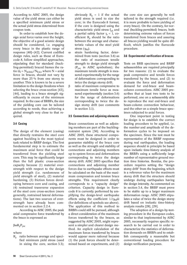
(Fig. 7).
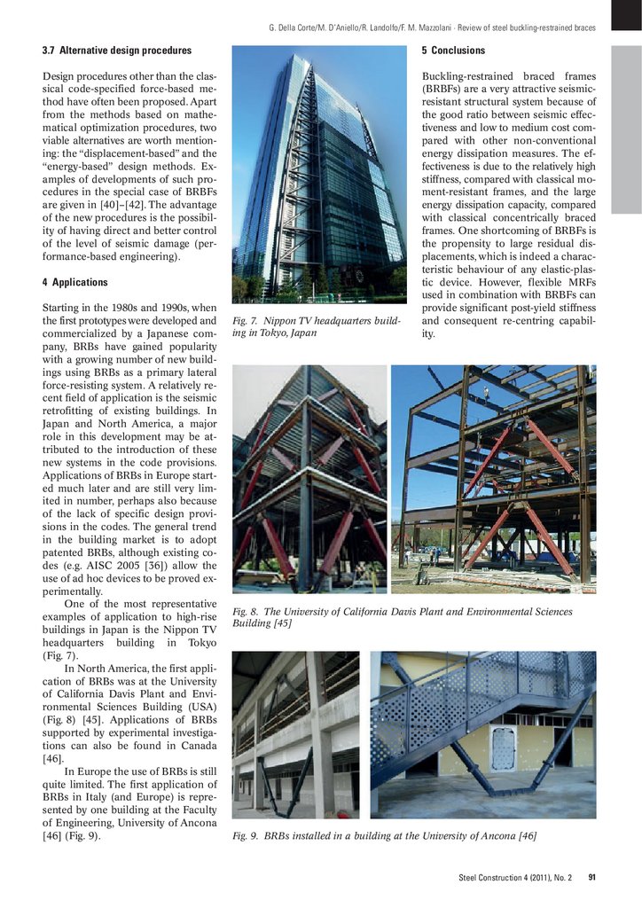
In North America, the first application of BRBs was at the University
of California Davis Plant and Environmental Sciences Building (USA)
(Fig. 8) [45]. Applications of BRBs
supported by experimental investigations can also be found in Canada
[46].
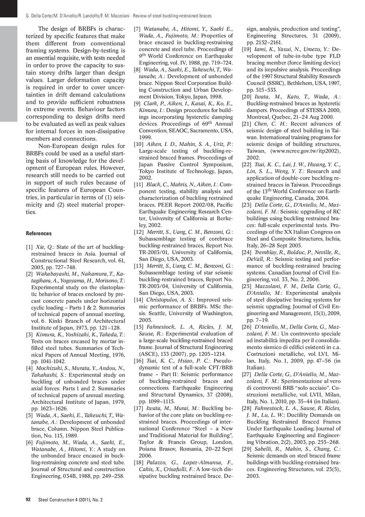
In Europe the use of BRBs is still
quite limited. The first application of
BRBs in Italy (and Europe) is represented by one building at the Faculty
of Engineering, University of Ancona
[46] (Fig. 9).
Fig. 7. Nippon TV headquarters building in Tokyo, Japan
Fig. 8. The University of California Davis Plant and Environmental Sciences
Building [45]
Fig. 9. BRBs installed in a building at the University of Ancona [46]
Steel Construction 4 (2011), No. 2
91
8.
G. Della Corte/M. D‘Aniello/R. Landolfo/F. M. Mazzolani · Review of steel buckling-restrained bracesThe design of BRBFs is characterized by specific features that make
them different from conventional
framing systems. Design-by-testing is
an essential requisite, with tests needed
in order to prove the capacity to sustain storey drifts larger than design
values. Larger deformation capacity
is required in order to cover uncertainties in drift demand calculations
and to provide sufficient robustness
in extreme events. Behaviour factors
corresponding to design drifts need
to be evaluated as well as peak values
for internal forces in non-dissipative
members and connections.
Non-European design rules for
BRBFs could be used as a useful starting basis of knowledge for the development of European rules. However,
research still needs to be carried out
in support of such rules because of
specific features of European Countries, in particular in terms of (1) seismicity and (2) steel material properties.
References
[1] Xie, Q.: State of the art of bucklingrestrained braces in Asia. Journal of
Constructional Steel Research, vol. 61,
2005, pp. 727–748.
[2] Wakabayashi, M., Nakamura, T., Katagihara, A., Yogoyama, H., Morisono, T.:
Experimental study on the elastoplastic behavior of braces enclosed by precast concrete panels under horizontal
cyclic loading – Parts 1 & 2. Summaries
of technical papers of annual meeting,
vol. 6. Kinki Branch of Architectural
Institute of Japan, 1973, pp. 121–128.
[3] Kimura, K., Yoshizaki, K., Takeda, T.:
Tests on braces encased by mortar infilled steel tubes. Summaries of Technical Papers of Annual Meeting, 1976,
pp. 1041-1042.
[4] Mochizuki, S., Murata, Y., Andou, N.,
Takahashi, S.: Experimental study on
buckling of unbonded braces under
axial forces: Parts 1 and 2. Summaries
of technical papers of annual meeting.
Architectural Institute of Japan, 1979,
pp. 1623–1626.
[5] Wada, A., Saeki, E., Takeuchi, T., Watanabe, A.: Development of unbonded
brace, Column. Nippon Steel Publication, No. 115, 1989.
[6] Fujimoto, M., Wada, A., Saeki, E.,
Watanabe, A., Hitomi, Y.: A study on
the unbonded brace encased in buckling-restraining concrete and steel tube.
Journal of Structural and construction
Engineering, 034B, 1988, pp. 249–258.
92
Steel Construction 4 (2011), No. 2
[7] Watanabe, A., Hitomi, Y., Saeki E.,
Wada, A., Fujimoto, M.: Properties of
brace encased in buckling-restraining
concrete and steel tube. Proceedings of
9th World Conference on Earthquake
Engineering, vol. IV, 1988, pp. 719–724.
[8] Wada, A., Saeki, E., Takeuchi, T., Watanabe, A.: Development of unbonded
brace. Nippon Steel Corporation Building Construction and Urban Development Division, Tokyo, Japan, 1998.
[9] Clark, P., Aiken, I., Kasai, K., Ko, E.,
Kimura, I.: Design procedures for buildings incorporating hysteretic damping
devices. Proceedings of 69th Annual
Convention, SEAOC, Sacramento, USA,
1999.
[10] Aiken, I. D., Mahin, S. A., Uriz, P.:
Large-scale testing of buckling-restrained braced frames. Proceedings of
Japan Passive Control Symposium,
Tokyo Institute of Technology, Japan,
2002.
[11] Black, C., Makris, N., Aiken, I.: Component testing, stability analysis and
characterization of buckling restrained
braces. PEER Report 2002/08, Pacific
Earthquake Engineering Research Center, University of California at Berkeley, 2002.
[12] Merritt, S., Uang, C. M., Benzoni, G.:
Subassemblage testing of corebrace
buckling-restrained braces, Report No.
TR-2003/01, University of California,
San Diego, USA, 2003.
[13] Merritt, S., Uang, C. M., Benzoni, G.:
Subassemblage testing of star seismic
buckling-restrained braces, Report No.
TR-2003/04, University of California,
San Diego, USA, 2003.
[14] Christopulos, A. S.: Improved seismic performance of BRBFs. MSc thesis. Seattle, University of Washington,
2005.
[15] Fahnestock, L. A, Ricles, J. M,
Sause, R.: Experimental evaluation of
a large-scale buckling-restrained braced
frame. Journal of Structural Engineering
(ASCE), 133 (2007), pp. 1205–1214.
[16] Tsai, K. C., Hsiao, P. C.: Pseudodynamic test of a full-scale CFT/BRB
frame – Part II: Seismic performance
of buckling-restrained braces and
connections. Earthquake Engineering
and Structural Dynamics, 37 (2008),
pp. 1099–1115.
[17] Iwata, M., Murai, M.: Buckling behavior of the core plate on buckling-restrained braces. Proceedings of international Conference “Steel – a New
and Traditional Material for Building”,
Taylor & Francis Group, London,
Poiana Brasov, Romania, 20–22 Sept
2006.
[18] Palazzo, G., Lopez-Almansa, F.,
Cahis, X., Crisafulli, F.: A low-tech dissipative buckling restrained brace. De-
sign, analysis, production and testing”,
Engineering Structures, 31 (2009),
pp. 2152–2161.
[19] Iami, K., Yasui, N., Umezu, Y.: Development of tube-in-tube type FLD
bracing member (force limiting device)
and its impulsive analysis. Proceedings
of the 1997 Structural Stability Research
Council (SSRC), Bethlehem, USA, 1997,
pp. 515–533.
[20] Iwata, M., Kato, T., Wada, A.:
Buckling-restrained braces as hysteretic
dampers. Proceedings of STESSA 2000,
Montreal, Quebec, 21–24 Aug 2000.
[21] Chen, C. H.: Recent advances of
seismic design of steel building in Taiwan. International training programs for
seismic design of building structures,
Taiwan, (www.ncree.gov.tw/itp2002),
2002.
[22] Tsai, K. C., Lai, J. W., Hwang, Y. C.,
Lin, S. L., Weng, Y. T.: Research and
application of double-core buckling restrained braces in Taiwan. Proceedings
of the 13th World Conference on Earthquake Engineering, Canada, 2004.
[23] Della Corte, G., D’Aniello, M., Mazzolani, F. M.: Seismic upgrading of RC
buildings using buckling restrained braces: full-scale experimental tests. Proceedings of the XX Italian Congress on
Steel and Composite Structures, Ischia,
Italy, 26–28 Sept 2005.
[24] Tremblay, R., Bolduc, P., Neville, R.,
DeVall, R.: Seismic testing and performance of buckling-restrained bracing
systems. Canadian Journal of Civil Engineering, vol. 33, No. 2, 2006.
[25] Mazzolani, F. M., Della Corte, G.,
D’Aniello, M.: Experimental analysis
of steel dissipative bracing systems for
seismic upgrading. Journal of Civil Engineering and Management, 15(1), 2009,
pp. 7–19.
[26] D’Aniello, M., Della Corte, G., Mazzolani, F. M.: Un controvento speciale
ad instabilità impedita per il consolidamento sismico di edifici esistenti in c.a.
Costruzioni metalliche, vol. LVI, Milan, Italy, No. 1, 2009, pp. 47–56 (in
Italian).
[27] Della Corte, G., D’Aniello, M., Mazzolani, F. M.: Sperimentazione al vero
di controventi BRB “solo acciaio”. Costruzioni metalliche, vol. LVII, Milan,
Italy, No. 1, 2010, pp. 35–44 (in Italian).
[28] Fahnestock, L. A., Sause, R. Ricles,
J. M., Lu, L. W.: Ductility Demands on
Buckling Restrained Braced Frames
Under Earthquake Loading. Journal of
Earthquake Engineering and Engineering Vibration, 2(2), 2003, pp. 255–268.
[29] Sabelli, R., Mahin, S., Chang, C.:
Seismic demands on steel braced frame
buildings with buckling-restrained braces. Engineering Structures, vol. 25(5),
2003.
9.
G. Della Corte/M. D‘Aniello/R. Landolfo/F. M. Mazzolani · Review of steel buckling-restrained braces[30] Kiggins, S., Uang, C. M.: Reducing
residual drift of buckling-restrained
braced frames as a dual system. Engineering Structures, 28 (2006),
pp. 1525–1532.
[31] Takeuchi, T., Ida, M., Yamada, S.,
Suzuki, K.: Estimation of cumulative
deformation capacity of buckling restrained braces. Journal of Structural
Engineering, vol. 134, No. 5 (2008),
pp. 822–831.
[32] Kim, J., Park, J., Shin, S. W., Min,
K. W.: Seismic performance of tubular
structures with buckling restrained
braces. The structural design of tall
and special buildings, 18 (2009),
pp. 351–370.
[33] Korzekwa, A., Tremblay, R.: Numerical simulation of the cyclic inelastic
behaviour of buckling restrained braces.
Proceedings of STESSA 2009, Philadelphia, USA, 2009.
[34] Ariyaratana, C., Fahnestock, L. A.:
Evaluation of buckling-restrained braced frame seismic performance considering reserve strength. Engineering
Structures, 33 (2011), pp. 77–89.
[35] BSSC/FEMA (2003). NEHRP Recommended provisions for seismic regulations for new buildings and other
structures (FEMA 450). Building Seismic Safety Council (BSSC) for Federal
Emergency
Management
Agency
(FEMA), National Institute of Building
Sciences, Washington, D.C., USA.
[36] ANSI/AISC 341-05 (2005). Seismic
provisions for structural steel buildings.
American Institute of Steel Construction Inc., Chicago, Illinois.
[37] European Committee for Standardization (CEN): Eurocode 8 – Design of
structures for earthquake resistance –
Part 1.1: General rules, seismic actions
and rules for buildings. EN 1998-1-1,
Brussels, 2005.
[38] ASCE: Minimum design loads for
buildings and other structures. ASCE/
SEI 7-10, American Society of Civil
Engineers/Structural Engineering Institute, Reston, Va., 2010.
[39] Della Corte, G., De Matteis, G.,
Landolfo, R., Mazzolani, F. M.: Seismic
analysis of MR steel frames based on
refined hysteretic models of connections. Journal of Constructional Steel
Research, 58 (2002), pp. 1331–1345.
[40] Choi, H., Kim, J.: Energy-based seismic design of buckling-restrained braced frames using hysteretic energy spectrum. Engineering Structures, 28 (2006),
pp. 304–311.
[41] Della Corte, G., Landolfo, R., Mazzolani, F. M.: Displacement-based seismic design of braced steel structures.
Steel Construction – Design and Research, 3, No. 3 (2010), pp. 134–139.
[42] Maley ,T. J., Sullivan, T. J., Della
Corte, G.: Development of a displacement-based design method for steel
dual systems with buckling-restrained
braces and moment-resisting frames.
Journal of Earthquake Engineering, 14:1
(2010), pp. 106–140.
[43] Elghazouli, A. Y.: Seismic design of
steel framed structures to Eurocode 8.
Proceedings of the 14th World Conference on Earthquake Engineering, Beijing, China, 12–17 Oct 2008.
[44] Mazzolani, F. M., Landolfo, R.,
Della Corte, G.: Eurocode 8 Provisions
for steel and steel-concrete composite
structures: Comments, critiques, im-
provement proposals and research
needs. Proceedings of the 1st ReLUIS
Project Final Conference, Naples, Italy,
1–3 Apr 2009.
[45] Clark, W., Kasai, K., Aiken, I. D.,
Kimura, I.: Evaluation of design methodologies for structures incorporating steel unbonded braces for energy
dissipation. Proceedings of the 12th
World Conference on Earthquake Engineering, Auckland, New Zealand,
2000.
[46] Antonucci, R., Balducci, F, Castellano, M. G., Donà, F.: Precast RC
Buildings with Buckling Restrained
Braces: the Example of the New Building of the Faculty of Engineering in
Ancona. Proceedings of the 2nd International fib Congress, Naples, Italy,
2006.
Keywords: Buckling-restrained braces;
seismic design; Eurocodes; design-bytesting
Authors:
Gaetano Della Corte
Department of Structural Engineering, University of Naples “Federico II”, [email protected]
Mario D’Aniello
Department of Construction and Mathematical
Methods in Architecture, University of Naples
“Federico II”, [email protected]
Raffaele Landolfo
Department of Construction and Mathematical
Methods in Architecture, University of Naples
“Federico II”, [email protected]
Federico M. Mazzolani
Department of Structural Engineering, University of Naples “Federico II”, [email protected]
Steel Construction 4 (2011), No. 2
93