 Construction
Similar presentations:


")

Review of Buckling-Restrained Brace Design and Application to Tall
1.
ctbuh.org/papersTitle:
Review of Buckling-Restrained Brace Design and Application to Tall
Buildings
Authors:
Toru Takeuchi, Department of Architecture and Building Engineering, Tokyo
Institute of Technology
Akira Wada, Professor Emeritus, Tokyo Institute of Technology
Subjects:
Construction
Seismic
Structural Engineering
Keywords:
Damping
Seismic
Publication Date:
2018
Original Publication:
International Journal of High-Rise Buildings Volume 7 Number 3
Paper Type:
1.
2.
3.
4.
5.
6.
Book chapter/Part chapter
Journal paper
Conference proceeding
Unpublished conference paper
Magazine article
Unpublished
© Council on Tall Buildings and Urban Habitat / Toru Takeuchi; Akira Wada
2.
International Journal of High-Rise BuildingsSeptember 2018, Vol 7, No 3, 187-195
https://doi.org/10.21022/IJHRB.2018.7.3.187
International Journal of
High-Rise Buildings
www.ctbuh-korea.org/ijhrb/index.php
Review of Buckling-Restrained Brace Design
and Application to Tall Buildings
Toru Takeuchi1,† and Akira Wada2
1
Department of Architecture and Building Engineering, Tokyo Institute of Technology, Japan
2
Professor Emeritus, Tokyo Institute of Technology, Japan
Abstract
Buckling-restrained braces (BRBs) are widely used as highly ductile seismic devices, with the first building using BRBs
completed in 1989 in Tokyo, and thousands more now in Japan, USA, Taiwan, China, New Zealand and other countries.
Although design codes of several countries specify BRB performance criteria, detailed design provisions are not necessarily
provided, as BRBs are typically treated as a manufactured device. This paper briefly reviews the early history of BRB research
and offers state-of-the-art views on the design criteria required to obtain stable and reliable performance. Representative project
examples and up-to-date studies relevant to tall buildings are summarized.
Keywords: Buckling-restrained brace, Damage tolerant, Grid skin, Damped outrigger
1. Introduction
Buckling-restrained braces (BRBs) are seismic devices
consisting of a primarily axially yielding core and an axially-decoupled restraining mechanism, which supresses
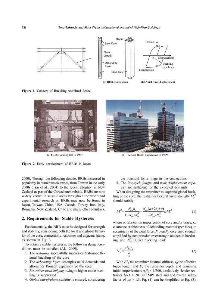
overall buckling. As shown in Fig. 1, a typical restrainer
consists of a steel hollow section filled with mortar, which
encases a yielding core wrapped in a thin debonding layer.
The debonding layer or gap provided between the core
and mortar (or all-steel restrainer) is an essential feature
of modern BRBs, limiting axial load transfer to the restrainer by providing a low friction interface and accommodating lateral expansion of the core resulting from Poisson effects. As a result, the energy dissipation characteristics of BRBs are excellent and compare favourably to
other fully ductile systems. For this reason, a properly
designed BRB may be employed as a hysteretic damper,
in many cases exhibiting sufficient fatigue capacity to
safely withstand multiple design level earthquakes with
no visible damage. Recently, a state-of-art textbook for
the design and application of this device was published
(Takeuchi and Wada, 2017). In this article, fundamental
BRB design criteria and application concepts for tall
buildings are discussed.
The basic concepts of buckling-restrained braces appeared in the 1970s, when limited experimental successes
were reported by several researchers in Japan and India.
The first practical BRB was achieved by Fujimoto et al.,
†
Corresponding author: Toru Takeuchi
Tel & Fax: +81-35-734-3165
E-mail: [email protected]
1988 (Fig. 2(a)). They employed rectangular steel tubes
with in-filled mortar for the restrainer, and determined the
optimal debonding material specifications to obtain stable
and symmetric hysteretic behavior. In addition, the basic
theory to design the restrainer was established and the
first project application soon followed in 1989. These BRBs
(unbonded braces) were applied to 10- and 15-story steel
frame office buildings in Tokyo (Fig. 2(b); Fujimoto et al.,
1990). BRBs subsequently increased in popularity and
other core and restrainer compositions soon followed,
notably the all-steel tube-in-tube type.
Through the 1990s, BRBs were used in approximately
160 buildings in Japan. In 1992, the concept of a “damage
tolerant structure” was proposed by Wada et al., 1992 and
1997, where BRBs are employed as energy dissipating
elasto-plastic dampers within an elastic main frame. The
AIJ design recommendations included BRBs design guidelines for the first time in 1996.
Collaboration with researchers and engineers in the US
soon led to the first international application, with the construction of a building at UC Davis in 1998 and followed
by an experiment at UC Berkeley in 2000 (Clark et al.,
1999). Numerous other buildings with BRBs were soon
constructed throughout California, including in seismic
retrofit applications. In the early 2000s, buckling-restrained
braced frames (BRBF) were first included in the Seismic
Provisions for Structural Steel Buildings (ANSI/AISC
341-05). During these early years of technology transfer
to international markets, a series of symposiums on passively controlled structures were held at Tokyo Institute
of Technology, sharing code developments, BRB designs,
and novel applications (Tokyo Institute of Technology,
3.
188Toru Takeuchi and Akira Wada | International Journal of High-Rise Buildings
Figure 1. Concept of Buckling-restrained Brace.
Figure 2. Early development of BRBs in Japan.
2000). Through the following decade, BRBs increased in
popularity in numerous countries, from Taiwan in the early
2000s (Tsai et al., 2004) to the recent adoption in New
Zealand as part of the Christchurch rebuild. BRBs are now
widely known in seismic areas throughout the world and
experimental research on BRBs may now be found in
Japan, Taiwan, China, USA, Canada, Turkey, Iran, Italy,
Romania, New Zealand, Chile and many other countries.
2. Requirements for Stable Hysteresis
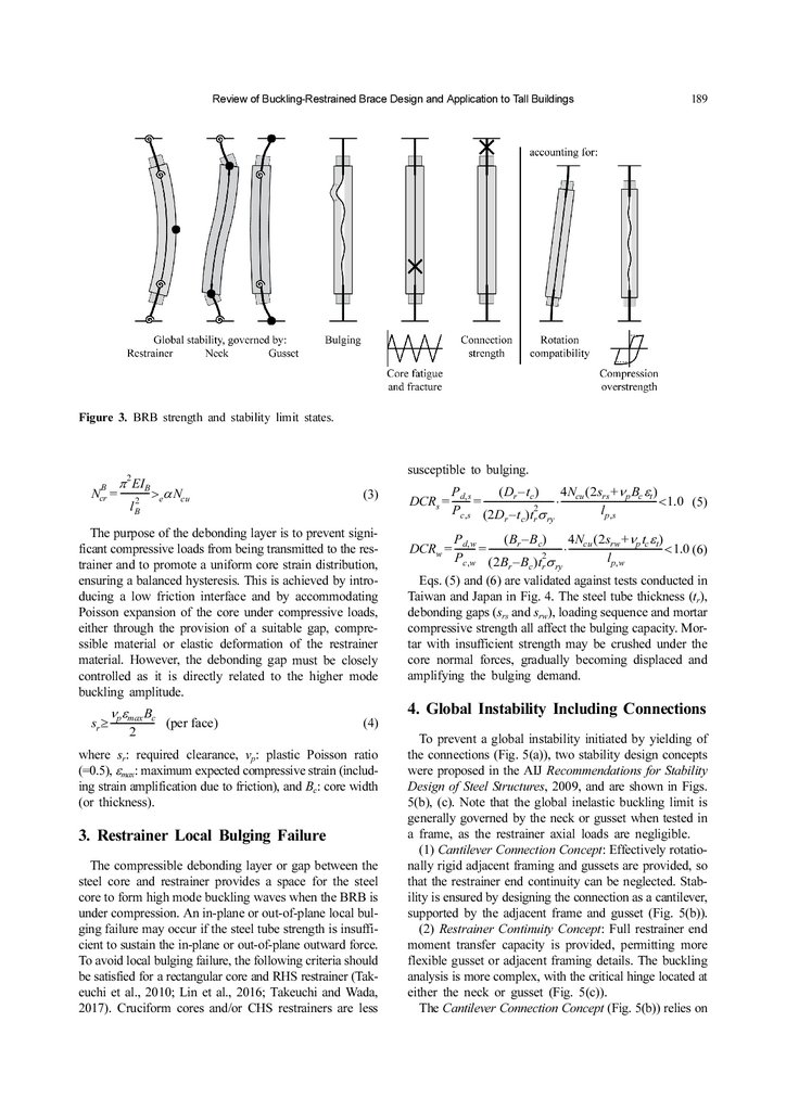
Fundamentally, the BRB must be designed for strength
and stability, considering both the local and global behavior of the core, connections, restrainer and adjacent frame,
as shown in Fig. 3.
To obtain a stable hysteresis, the following design conditions must be satisfied (AIJ, 2009).
1. The restrainer successfully suppresses first-mode flexural buckling of the core
2. The debonding layer decouples axial demands and
allows for Poisson expansion of the core
3. Restrainer local bulging owing to higher mode buckling is suppressed
4. Global out-of-plane stability is ensured, considering
the potential for a hinge in the connections
5. The low-cycle fatigue and peak displacement capacity are sufficient for the expected demands
When designing the restrainer to suppress global buckB
ling of the core, the restrainer flexural yield strength My
should satisfy:
Ncu (a + 2sr + e)
Ncu ac
B
- = -------------------------------- ≤ MyB
M = ----------------------E
E
1 – Ncu /Ncr
1 – Ncu /Ncr
(1)
where a: fabrication imperfection of core and/or brace, sr:
clearance or thickness of debonding material (per face), e:
eccentricity of the axial force, Ncu=dαNy: core yield strength
amplified by compression overstrength and strain hardenE
ing, and Ncr : Euler buckling load:
2
E π EIB
Ncr = -----------2
lB
(2)
With EIB the restrainer flexural stiffness, lB the effective
brace length and Dr the restrainer depth, and assuming
initial imperfections ac/lB ≤ 1/500, a relatively slender restrainer lB/Dr > 20, 330 MPa steel and and overall safety
factor of eα ≥ 1.5, Eq. (1) can be simplified to Eq. (3).
4.
Review of Buckling-Restrained Brace Design and Application to Tall Buildings189
Figure 3. BRB strength and stability limit states.
susceptible to bulging.
2
π EIB
- >eαNcu
= -----------2
lB
(3)
4Ncu (2srs +νp Bc εt)
P d, s
( Dr – t c )
- = ------------------------------- < 1.0 (5)
DCRs = ------⋅ -----------------------------------------2
l p, s
Pc, s (2D – t )t σ
r c r ry
The purpose of the debonding layer is to prevent significant compressive loads from being transmitted to the restrainer and to promote a uniform core strain distribution,
ensuring a balanced hysteresis. This is achieved by introducing a low friction interface and by accommodating
Poisson expansion of the core under compressive loads,
either through the provision of a suitable gap, compressible material or elastic deformation of the restrainer
material. However, the debonding gap must be closely
controlled as it is directly related to the higher mode
buckling amplitude.
4Ncu (2srw +νp tc εt)
P d, w
( Br – Bc )
- ⋅ ----------------------------------------- < 1.0 (6)
DCRw = --------= -------------------------------2
l p, w
Pc, w (2B – B )t σ
r
c r ry
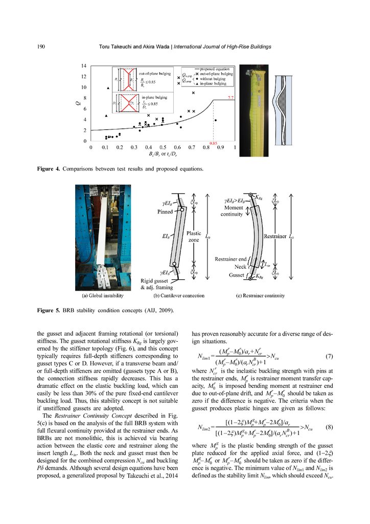
Eqs. (5) and (6) are validated against tests conducted in
Taiwan and Japan in Fig. 4. The steel tube thickness (tr),
debonding gaps (srs and srw), loading sequence and mortar
compressive strength all affect the bulging capacity. Mortar with insufficient strength may be crushed under the
core normal forces, gradually becoming displaced and
amplifying the bulging demand.
B
Ncr
νpεmax Bc
- (per face )
sr ≥ ------------------2
4. Global Instability Including Connections
(4)
where sr: required clearance, νp: plastic Poisson ratio
(=0.5), εmax: maximum expected compressive strain (including strain amplification due to friction), and Bc: core width
(or thickness).
3. Restrainer Local Bulging Failure
The compressible debonding layer or gap between the
steel core and restrainer provides a space for the steel
core to form high mode buckling waves when the BRB is
under compression. An in-plane or out-of-plane local bulging failure may occur if the steel tube strength is insufficient to sustain the in-plane or out-of-plane outward force.
To avoid local bulging failure, the following criteria should
be satisfied for a rectangular core and RHS restrainer (Takeuchi et al., 2010; Lin et al., 2016; Takeuchi and Wada,
2017). Cruciform cores and/or CHS restrainers are less
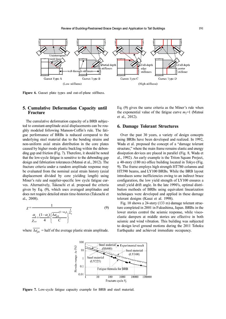
To prevent a global instability initiated by yielding of
the connections (Fig. 5(a)), two stability design concepts
were proposed in the AIJ Recommendations for Stability
Design of Steel Structures, 2009, and are shown in Figs.
5(b), (c). Note that the global inelastic buckling limit is
generally governed by the neck or gusset when tested in
a frame, as the restrainer axial loads are negligible.
(1) Cantilever Connection Concept: Effectively rotationally rigid adjacent framing and gussets are provided, so
that the restrainer end continuity can be neglected. Stability is ensured by designing the connection as a cantilever,
supported by the adjacent frame and gusset (Fig. 5(b)).
(2) Restrainer Continuity Concept: Full restrainer end
moment transfer capacity is provided, permitting more
flexible gusset or adjacent framing details. The buckling
analysis is more complex, with the critical hinge located at
either the neck or gusset (Fig. 5(c)).
The Cantilever Connection Concept (Fig. 5(b)) relies on
5.
190Toru Takeuchi and Akira Wada | International Journal of High-Rise Buildings
Figure 4. Comparisons between test results and proposed equations.
Figure 5. BRB stability condition concepts (AIJ, 2009).
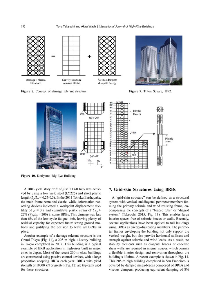
the gusset and adjacent framing rotational (or torsional)
stiffness. The gusset rotational stiffness KRg is largely governed by the stiffener topology (Fig. 6), and this concept
typically requires full-depth stiffeners corresponding to
gusset types C or D. However, if a transverse beam and/
or full-depth stiffeners are omitted (gussets type A or B),
the connection stiffness rapidly decreases. This has a
dramatic effect on the elastic buckling load, which can
easily be less than 30% of the pure fixed-end cantilever
buckling load. Thus, this stability concept is not suitable
if unstiffened gussets are adopted.
The Restrainer Continuity Concept described in Fig.
5(c) is based on the analysis of the full BRB system with
full flexural continuity provided at the restrainer ends. As
BRBs are not monolithic, this is achieved via bearing
action between the elastic core and restrainer along the
insert length Lin. Both the neck and gusset must then be
designed for the combined compression Ncu and buckling
Pδ demands. Although several design equations have been
proposed, a generalized proposal by Takeuchi et al., 2014
has proven reasonably accurate for a diverse range of design situations.
r
r
r
(Mp – M0)/ar + Ncr
- > Ncu
Nlim1 = ----------------------------------------------(7)
r
r
B
(Mp – M0)/(ar Ncr ) + 1
r
where Ncr is the inelastic buckling strength with pins at
r
the restrainer ends, Mp is restrainer moment transfer capr
acity, M0 is imposed bending moment at restrainer end
r
r
due to out-of-plane drift, and Mp – M0 should be taken as
zero if the difference is negative. The criteria when the
gusset produces plastic hinges are given as follows:
g
r
r
[ (1 – 2ξ )Mp + Mp – 2M0]/ar
Nlim2 = ------------------------------------------------------------------------------> Ncu
g
r
r
B
[ (1 – 2ξ )Mp + Mp – 2M0]/(ar Ncr ) + 1
g
(8)
where Mp is the plastic bending strength of the gusset
plate reduced for the applied axial force, and (1−2ξ)
g
r
r
r
Mp – M0 or Mp – M0 should be taken as zero if the difference is negative. The minimum value of Nlim1 and Nlim2 is
defined as the stability limit Nlim, which should exceed Ncu.
6.
Review of Buckling-Restrained Brace Design and Application to Tall Buildings191
Figure 6. Gusset plate types and out-of-plane stiffness.
5. Cumulative Deformation Capacity until
Fracture
The cumulative deformation capacity of a BRB subjected to constant-amplitude axial displacements can be roughly modeled following Manson-Coffin’s rule. The fatigue performance of BRBs is reduced compared to the
underlying steel material due to the bending strains and
non-uniform axial strain distribution in the core plates
caused by higher mode plastic buckling within the debonding gap and friction (Fig. 7). Therefore, it should be noted
that the low-cycle fatigue is sensitive to the debonding gap
design and fabrication tolerances (Matsui et al., 2012). The
fracture criteria under a random amplitude response may
be evaluated from the nominal axial strain history (axial
displacement divided by core yielding length) using
Miner’s rule and supplier-specific low cycle fatigue curves. Alternatively, Takeuchi et al. proposed the criteria
given by Eq. (9), which uses averaged amplitudes and
does not require detailed strain time-histories (Takeuchi et
al., 2008).
1
χ = ------------------------------------------------------------1
(1 + m2) ----m2
(9)
α (1 – αs) ⎧Δεph
⎫
------s- + --------------- ⎨---------------------- ⎬
4 ⎩
χ so
C
⎭
where Δεph = half of the average plastic strain amplitude.
Eq. (9) gives the same criteria as the Miner’s rule when
the exponential value of the fatigue curve m2=1 (Matsui
et al., 2012).
6. Damage Tolerant Structures
Over the past 30 years, a variety of design concepts
using BRBs have been developed and realized. In 1992,
Wada et al. proposed the concept of a “damage tolerant
structure,” where the main frame remains elastic and energy
dissipation devices are placed in parallel (Fig. 8, Wada et
al., 1992). An early example is the Triton Square Project,
a 40-story (180 m) office building located in Tokyo (Fig.
9). The frame employs high strength HT780 columns and
HT590 beams, and LY100 BRBs. While the BRB layout
introduces some inefficiencies owing to an indirect brace
configuration, the low yield strength of LY100 ensures a
small yield drift angle. In the late 1990’s, optimal distribution methods of BRBs using equivalent linearization
techniques were developed and applied in these damage
tolerant designs (Kasai et al. 1998).
Fig. 10 shows a 24-story (133 m) damage tolerant structure completed in 2001 in Fukushima, Japan. BRBs in the
lower stories control the seismic response, while viscoelastic dampers at middle stories are effective in both
seismic and wind vibration. This building was subjected
to design level ground motions during the 2011 Tohoku
Earthquake and achieved immediate occupancy.
Figure 7. Low-cycle fatigue capacity example for BRB and steel material.
7.
192Toru Takeuchi and Akira Wada | International Journal of High-Rise Buildings
Figure 8. Concept of damage tolerant structure.
Figure 9. Triton Square, 1992.
Figure 10. Koriyama Big-Eye Building.
A BRB yield story drift of just 0.13-0.16% was achieved by using a low yield steel (LY225) and short plastic
length (Lp/L0 = 0.25-0.3). In the 2011 Tohoku Earthquake,
the main frame remained elastic, while deformation recording devices indicated a workpoint displacement ductility of µ ≈ 3.8 and cumulative plastic strain of ∑εp ≈
22% (∑εp/εy ≈ 200) in some BRBs. This damage was less
than 6% of the low cycle fatigue limit, leaving plenty of
residual capacity for expected future strong ground motions and justifying the decision to leave all BRBs in
place.
Another example of a damage tolerant structure is the
Grand Tokyo (Fig. 11), a 205 m high, 43-story building
in Tokyo completed in 2007. This building is a typical
example of BRB application in high-rises built in major
cities in Japan. Most of the recent 200 m-class buildings
are constructed using passive control devices, with a large
proportion adopting BRBs each year. BRBs with yield
strength of 10000 kN or greater (Fig. 12) are typically used
for these structures.
7. Grid-skin Structures Using BRBs
A “grid-skin structure” can be defined as a structural
system with vertical and diagonal perimeter members forming the primary seismic and wind resisting frame, encompassing the concepts of a “braced tube” or “diagrid
system” (Takeuchi, 2015; Fig. 13). This enables large
interior spaces free of seismic braces or walls. Recently,
several applications have been applied to tall buildings
using BRBs as energy-dissipating members. The perimeter frames enveloping the building not only support the
vertical weight, but also provide horizontal stiffness and
strength against seismic and wind loads. As a result, no
stability elements such as diagonal braces or concrete
shear walls are required in internal spaces, which permits
a flexible interior design and renovation throughout the
building’s lifetime. A recent example is shown in Fig. 14.
This 205-m high building completed in San Francisco is
covered by damped mega-braces composed of BRBs and
viscous dampers, producing equivalent damping of 8%
8.
Review of Buckling-Restrained Brace Design and Application to Tall BuildingsFigure 11. Tokyo BRBF (Gran Tokyo North).
Figure 13. Grid-skin structures.
Figure 14. 181 Fremont Tower, San Francisco (Alumfti et al., 2018).
Figure 12. Erection of large BRBF.
193
9.
194Toru Takeuchi and Akira Wada | International Journal of High-Rise Buildings
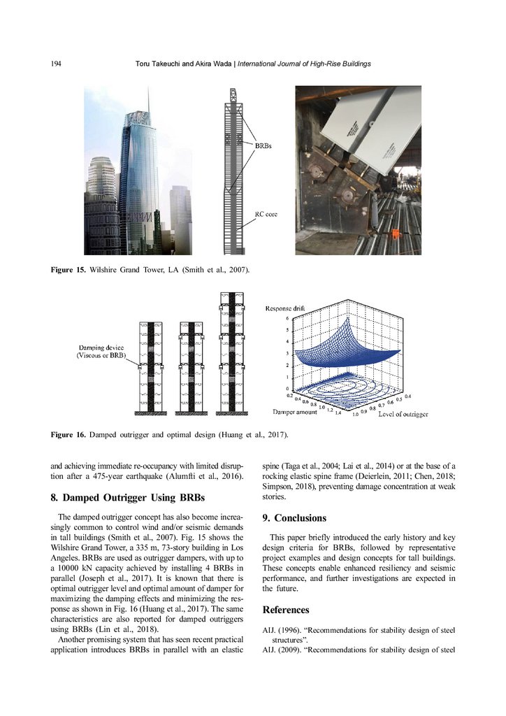
Figure 15. Wilshire Grand Tower, LA (Smith et al., 2007).
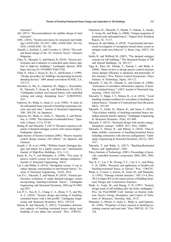
Figure 16. Damped outrigger and optimal design (Huang et al., 2017).
and achieving immediate re-occupancy with limited disruption after a 475-year earthquake (Alumfti et al., 2016).
8. Damped Outrigger Using BRBs
The damped outrigger concept has also become increasingly common to control wind and/or seismic demands
in tall buildings (Smith et al., 2007). Fig. 15 shows the
Wilshire Grand Tower, a 335 m, 73-story building in Los
Angeles. BRBs are used as outrigger dampers, with up to
a 10000 kN capacity achieved by installing 4 BRBs in
parallel (Joseph et al., 2017). It is known that there is
optimal outrigger level and optimal amount of damper for
maximizing the damping effects and minimizing the response as shown in Fig. 16 (Huang et al., 2017). The same
characteristics are also reported for damped outriggers
using BRBs (Lin et al., 2018).
Another promising system that has seen recent practical
application introduces BRBs in parallel with an elastic
spine (Taga et al., 2004; Lai et al., 2014) or at the base of a
rocking elastic spine frame (Deierlein, 2011; Chen, 2018;
Simpson, 2018), preventing damage concentration at weak
stories.
9. Conclusions
This paper briefly introduced the early history and key
design criteria for BRBs, followed by representative
project examples and design concepts for tall buildings.
These concepts enable enhanced resiliency and seismic
performance, and further investigations are expected in
the future.
References
AIJ. (1996). “Recommendations for stability design of steel
structures”.
AIJ. (2009). “Recommendations for stability design of steel
10.
Review of Buckling-Restrained Brace Design and Application to Tall Buildingsstructures”.
AIJ. (2017). “Recommendations for stability design of steel
structures”.
AISC. (2016). “Seismic provisions for structural steel buildings (ANSI/AISC 341-05)”, 2002, (ANSI/AISC 341-10),
2010, (ANSI/AISC 341-16).
Alumfti, I., Krolicki, J., and Crowther, A. (2016). “The resilient-based design of the 181 Fremont Tower.” Structure
Magazine.
Chen, X., Takeuchi, T., and Matsui, R. (2018). “Seismic performance and evaluation of controlled spine frames applied in high-rise buildings.” Earthquake Spectra, DOI:
https://doi.org/10.1193/080817EQS157M.
Clark, P., Aiken, I., Kasai, K., Ko, E., and Kimura, I. (1999).
“Design procedure for buildings incorporating hysteretic
damping devices.” 68th annual convention SEAOC, CA,
355-371.
Deierlein, G., Ma, X., Eatherton, M., Hajjar, J., Krawinkler,
H., Takeuchi, T., Kasai, K., and Midorikawa, M. (2011).
“Earthquake resilient steel braced frames with controlled
rocking and energy dissipating fuses.” EUROSTEEL
2011.
Fujimoto, M., Wada, A., Saeki, E., et al. (1988). “A study on
the unbounded brace encased in buckling-restraining concrete and steel tube.” Journal of Structural Engineering,
34B: 249-258. (in Japanese)
Fujimoto, M., Wada, A., Saeki, E., Takeuchi, T., and Watanabe, A. (1990). “Development of unbonded brace.” Quarterly Column, (115), 91-96.
Huang, B. and Takeuchi, T. (2017).“Dynamic response evaluation of damped-outrigger systems with various heights.”
Earthquake Spectra.
Japan Society of Seismic Isolation (2005). “Passive response
control design manual, 2nd edition.” (in Japanese and
Chinese)
Joseph, L. M. et al. (1998). “Wilshire Grand: Outrigger designs and details for a highly seismic site.” International
Journal of High-Rise Buildings, 5(1), 1-12.
Kasai, K., Fu, Y., and Watanabe, A. (1998). “Two types of
passive control systems for seismic damage mitigation.”
Journal of Structural Engineering, ASCE.
Lai, J. and Mahin, S. (2014). “Strongback system: A way to
reduce damage concentration in steel-braced frames.” Journal of Structural Engineering, 141(9), 2014.
Lin, P. C., Takeuchi, T., and Matsui, R. (2018). “Seismic performance evaluation of single damped-outrigger system
incorporating buckling-restrained braces”, Earthquake
Engineering and Structural Dynamics, DOI.org/10.1002/
eqe.3072
Lin, P. C., Tsai, K. C., Chang, C. A., Hsiao, Y. Y., and Wu,
A. C. (2016). “Seismic design and testing of bucklingrestrained braces with a thin profile”, Earthquake Engineering and Structural Dynamics, 45(3), 339-358.
Matsui, R. and Takeuchi, T., (2012). “Cumulative deformation capacity of buckling restrained braces taking local
buckling of core plates into account”. Proc. 15WCEE.
195
Nakamura, H., Takeuchi, T., Maeda, Y., Nakata, Y., Sasaki,
T., Iwata, M., and Wada, A. (2000). “Fatigue properties of
practical-scale unbonded braces”. Nippon Steel Technical
Report, 82, 51-57.
Simpson, B. and Mahin, S. (2018). “Experimental and numerical investigation of strongback braced frame system to
mitigate weak story behavior”, J. Struct. Eng., ASCE, 144
(2).
Smith, R. and Willford, M. (2007). “The damped outrigger
concept for tall buildings.” The Structural Design of Tall
and Special Buildings, 16, 501-217.
Taga, K., Koto, M., Tokuda, Y., Tsuruta, J., and Wada, A.
(2004). “Hints on how to design passive control structure
whose damper efficiency is enhanced, and practicality of
this structure.” Proc. Passive Control Symposium, Tokyo
Institute of Technology, Japan, 105-112.
Takeuchi, T., Ida, M., Yamada, S., and Suzuki, K. (2008).
“Estimation of cumulative deformation capacity of buckling restrained braces.” ASCE Journal of Structural Engineering, 134(5), 822-831.
Takeuchi, T., Hajjar, J. F., Matsui, R., et al. (2014). “Local
buckling resistant condition for core plates in buckling restrained braces.” Journal of Constructional Steel Research,
66(2), 139-149.
Takeuchi, T., Ozaki, H., Matsui, R., and Sutcu, F. (2014),
“Out-of-plane stability of buckling-restrained braces including moment transfer capacity.” Earthquake Engineering
& Structural Dynamics, 43(6), 851-869.
Takeuchi, T. (2015). “Structural design with seismic energydissipation concept.” IABSE 2015, Proc. IABSE.
Takeuchi, T., Matsui, R., and Mihara, S. (2016). “Out-ofplane stability assessment of buckling-restrained braces
including connections with chevron configuration.” Earthquake Engineering & Structural Dynamics, 45(12), 18951917.
Takeuchi, T. and Wada, A. (2017). “Buckling-Restrained
Braces and Applications”, JSSI.
Tokyo Institute of Technology. (2001). Proceedings of passively controlled structures symposium; 2000, 2001, 2002,
2004.
Tsai, K. C., Lai, J. W., Hwang, Y. C., Lin, S. L., and Weng,
C. H. (2004). “Research and application of double-core
buckling-restrained braces in Taiwan.” Proc. 13WCEE.
Wada, A., Connor, J., Kawai, H., Iwata, M., and Watanabe,
A. (1992). “Damage tolerant structure.” ATC-15-4, Proc.
5th US-Japan WS on the Improvement of Building Structural Design and Construction Practices.
Wada, A., Iwata, M., and Huang, Y. H. (1997). “Seismic
design trend of tall building after the Kobe earthquake.”
Proc. Int. Post-SMiRT Conf. Seminar on Seismic Isolation, Passive Energy Dissipation, and Control of Vibrations of Structures, Taormina, Italy, 25-27.
Watanabe, A., Hitomi, Y., Saeki, E., Wada, A., and Fujimoto,
M. (1988). “Properties of brace encased in buckling-restraining concrete and steel tube.” Proc. 9WCEE, IV, 719724.