


 Construction
Similar presentations:


")


Design of a steel structure for a large span roof with emphasis on the verification of bolted connections
1.
Design of a steel structure for a large span roofwith emphasis on the verification of bolted connections
David Alexandre Ferreira Ivo
Thesis submitted in partial fulfilment of the requirements for the
degree of Master of Science in
Civil Engineering
Supervisor: Professor Pedro Antonio Martins Mendes
Examination Committee
Chairman: Professor Jorge Miguel Silveira Filipe Mascarenhas
Proença
Supervisor: Professor Pedro Antonio Martins Mendes
Member of the Committee: Professor José Joaquim Costa Branco
de Oliveira Pedro
July 2016
2.
AbstractThe main objective of the thesis is the conceptual and detailed design of a steel structure for large span
roofing by means of lattice girders.
These procedures include a conceptual analysis of a proposed roofing system (36x56 meters) as well as
the detailed checking of the members and connections in accordance to EN 1993. For the purpose of
analysis, the structure is modelled with the software SAP2000 as a series of 2D structures, effectively
simulating the path of forces in the structure.
Regarding the connections, focus is given to detailed design under ultimate limit state of gusset plates as
well as spliced plate connections used for chord continuity. Serviceability is evaluated in terms of overall
deflection and taking into account the effects of slack recovery.
Key-words: Lattice girders, bolted joints, large span roofs
ii
3.
4.
ResumoO trabalho tem por objetivo a conceção e dimensionamento de uma estrutura metálica para uma
cobertura de grande vão utilizando estruturas reticuladas de aço.
Para o efeito, o trabalho envolve a conceção duma estrutura triangulada, com perfis laminados a quente,
para cobertura dum vão grande (36x56) e, posteriormente, a verificação da segurança dos principais
elementos, sistema de contraventamento e ligações, assim como do estado limite de deformação de
acordo com a EN 1993. Por forma a ter em conta o encaminhamento das cargas nos vários elementos
estruturais, foi elaborada uma sequência de modelos 2D usando o programa de cálculo SAP2000.
Neste contexto, é dado destaque ao dimensionamento e pormenorização de juntas com ligações
aparafusadas e recurso a chapas gousset; em relação ao estado limite de deformação, é avaliado o
efeito das folgas no caso das ligações aparafusadas.
Palavras chave: Estruturas reticuladas, juntas aparafusadas, coberturas de grande vão
iv
5.
6.
AcknowledgementsThis thesis is the product of an increasing knowledge through the many hours of work during these
years at IST. I am indebted to my Supervisor, Professor Pedro Mendes, for his guidance, always rich
with friendly and constructive criticism without whom the elaboration of thesis would not be possible. In
addition to Professor Pedro Mendes, I must also refer that Professors Luís Guerreiro, José Oliveira
Pedro, Rita Bento and Luís Castro, were among the most important and influential professors during
the degree and from whom I have learnt a great deal. I dare not list the many others to whom I am
indebted, less I do some injustice by inadvertently omitting their names. But I cannot refrain from
mentioning my mother Stella, brother Tiago and uncle and aunt José and Teresa for their love and
support as well as their willingness to accept nothing less than my full commitment to the degree I
endeavoured to.
vi
7.
1 Contents1.
2
3.
4.
Introduction .................................................................................................................................1
1.1
General historical overview ..................................................................................................1
1.2
Main objectives and framework ............................................................................................2
Trusses in single story buildings ..................................................................................................3
2.1
Main functions .....................................................................................................................3
2.2
Truss layouts .......................................................................................................................3
2.3
Roof structures ....................................................................................................................5
2.3.1
General geometry ........................................................................................................5
2.3.2
Cross-sections of members ..........................................................................................5
Adopted solution .........................................................................................................................7
3.1
General overview.................................................................................................................7
3.2
Members and materials .......................................................................................................8
3.3
Connections ........................................................................................................................9
3.3.1
General overview .........................................................................................................9
3.3.2
Main truss to columns ................................................................................................ 10
3.3.3
Continuity of the chords.............................................................................................. 11
3.3.4
Diagonals to chords ................................................................................................... 11
Design Loads and Modelling ..................................................................................................... 13
4.1
4.1.1
Dead Load (DL) ......................................................................................................... 13
4.1.2
Live load (LL) ............................................................................................................. 13
4.1.3
Snow load (SN) .......................................................................................................... 13
4.1.4
Wind load (WL) .......................................................................................................... 13
4.1.5
Load Combinations .................................................................................................... 15
4.2
5.
Loads ................................................................................................................................ 13
Modelling ........................................................................................................................... 16
4.2.1
General overview ....................................................................................................... 16
4.2.2
Stiffness and secondary forces................................................................................... 17
4.2.3
Clearance and deflection............................................................................................ 19
Verification of Members ............................................................................................................. 23
5.1
Members in Compression .................................................................................................. 23
vii
8.
5.26
Members in Tension .......................................................................................................... 33
Verification of Connections ........................................................................................................ 37
6.1
6.1.1
Loads and general geometry ...................................................................................... 37
6.1.2
Gusset to chord.......................................................................................................... 39
6.1.3
Diagonals to gusset.................................................................................................... 42
6.2
7
Detailed design of KT joint No. 10 ...................................................................................... 37
Detailed design of a continuous chord connection using a splice plate ............................... 65
6.2.1
Loads and general geometry ...................................................................................... 65
6.2.2
Web component ......................................................................................................... 67
6.2.3
Flange component ..................................................................................................... 73
Conclusion and Future Developments ....................................................................................... 79
7.1
General Conclusions ......................................................................................................... 79
7.2
Future Developments......................................................................................................... 79
7
viii
References................................................................................................................................ 80
9.
List of FiguresFigure 1 – Camille Polonceau truss (left); Robert Stephenson’s locomotive roundhouse (right) ............2
Figure 2 – General layout of the roof structure.....................................................................................7
Figure 3 – Main truss and member numbering.....................................................................................8
Figure 4 – Layout of the bracing truss (upper) and main truss (lower); (Dimensions in [m]) ..................8
Figure 5 – Connection concept for the lower chord ............................................................................ 10
Figure 6 – Spliced connection (left); end-plate connection (right) ....................................................... 11
Figure 7 – Bolted gusset to T chord (left); welded gusset to H or I chord flange (centre); welded
gusset to H or I chord web (right) ...................................................................................................... 12
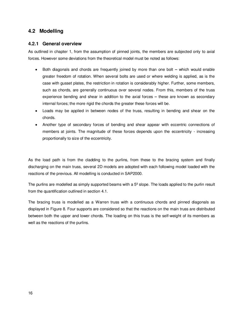
Figure 8 – Model of the bracing truss. ............................................................................................... 17
Figure 9 – Model of the main truss .................................................................................................... 17
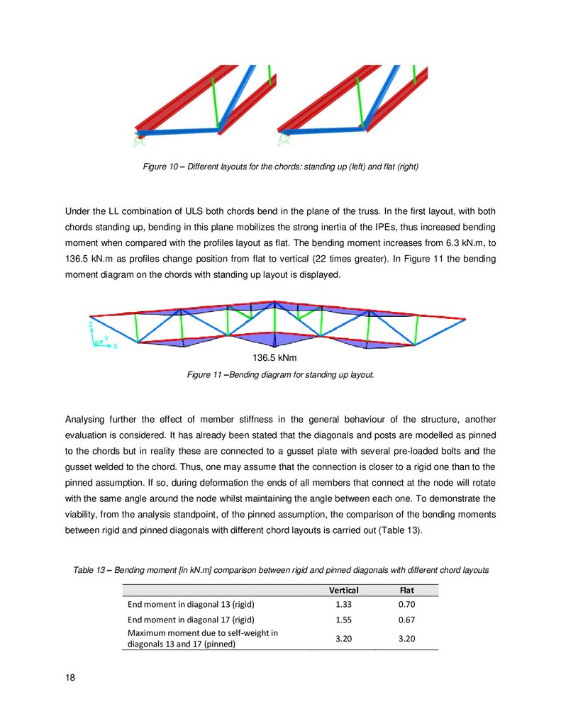
Figure 10 – Different layouts for the chords: standing up (left) and flat (right) ..................................... 18
Figure 11 –Bending diagram for standing up layout. .......................................................................... 18
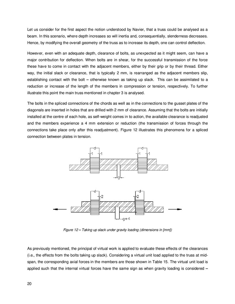
Figure 12 – Taking up slack under gravity loading (dimensions in [mm]) ............................................ 20
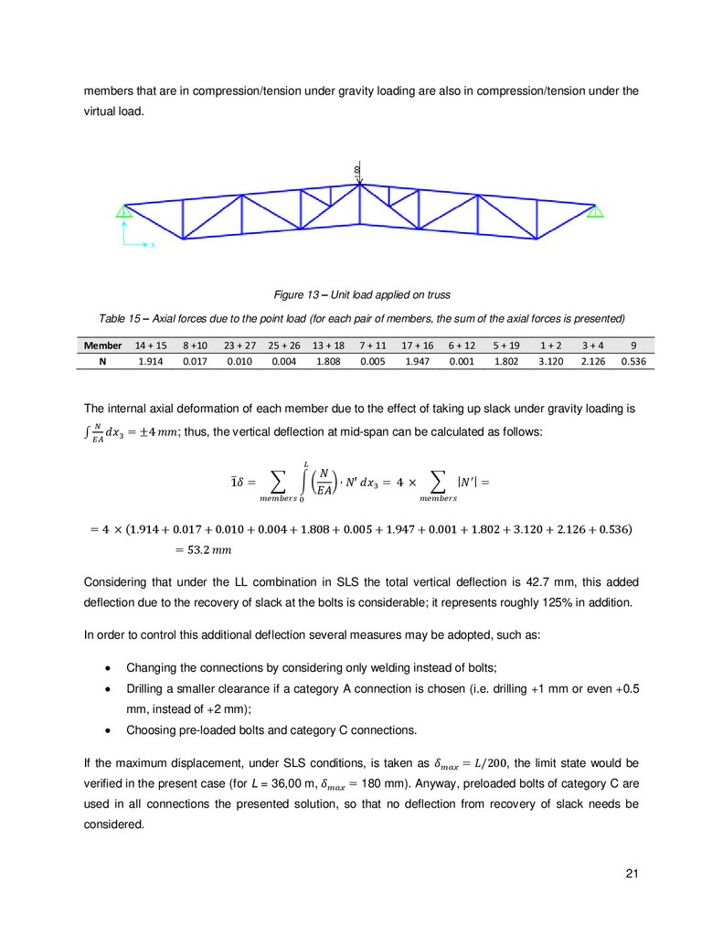
Figure 13 – Unit load applied on truss ............................................................................................... 21
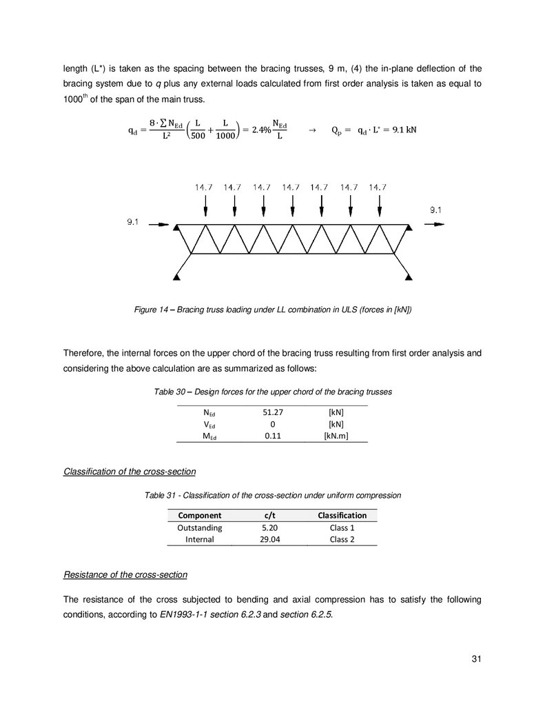
Figure 14 – Bracing truss loading under LL combination in ULS (forces in [kN]) ................................. 31
Figure 15 – Net areas ....................................................................................................................... 34
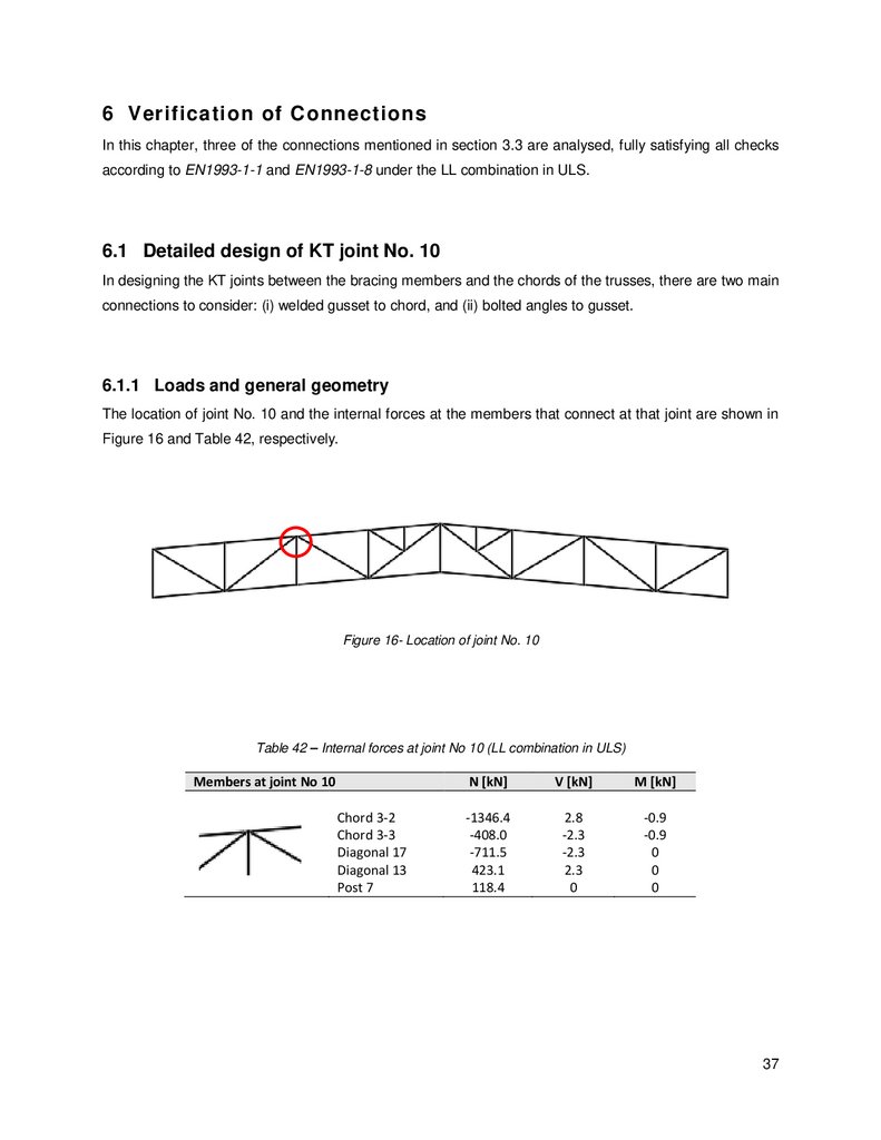
Figure 16- Location of joint No. 10..................................................................................................... 37
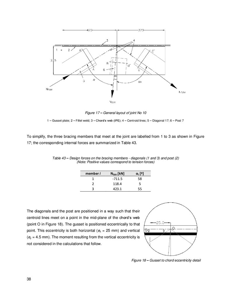
Figure 17 – General layout of joint No 10 .......................................................................................... 38
Figure 18 – Gusset to chord eccentricity detail .................................................................................. 38
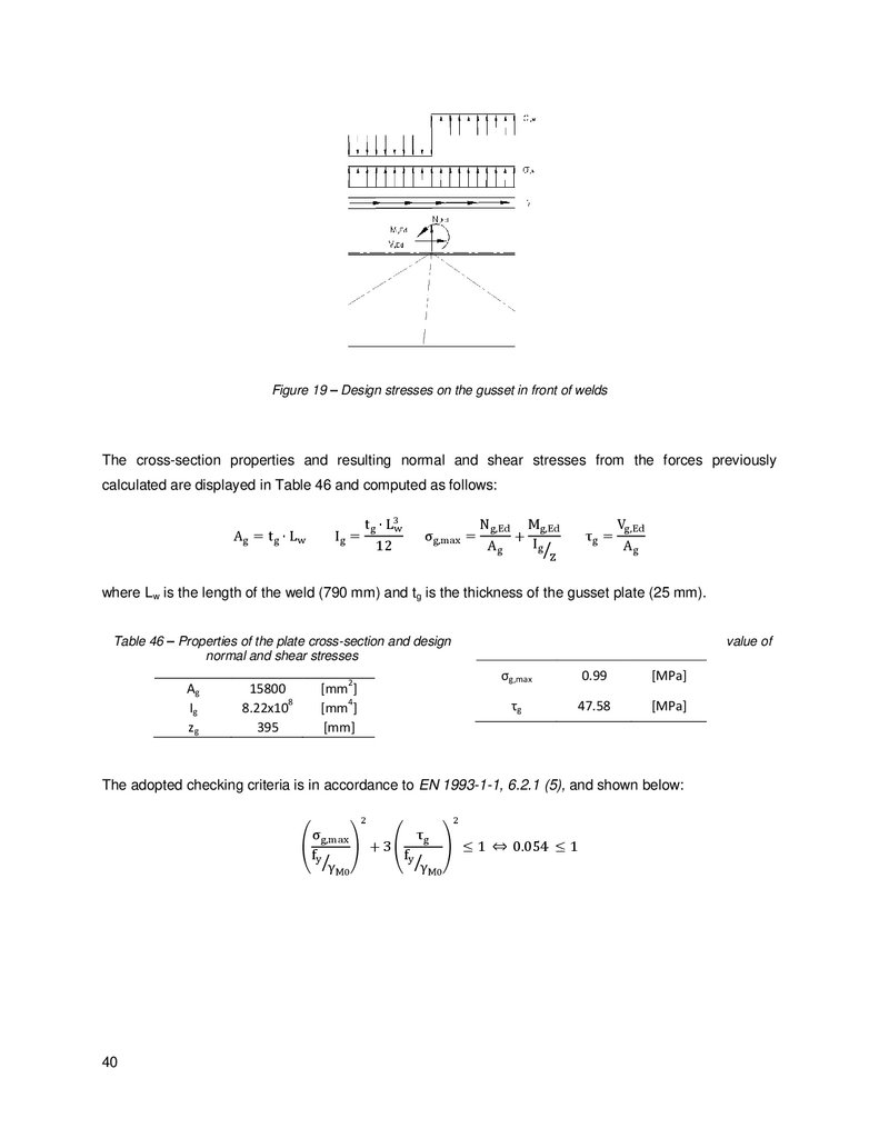
Figure 19 – Design stresses on the gusset in front of welds ............................................................... 40
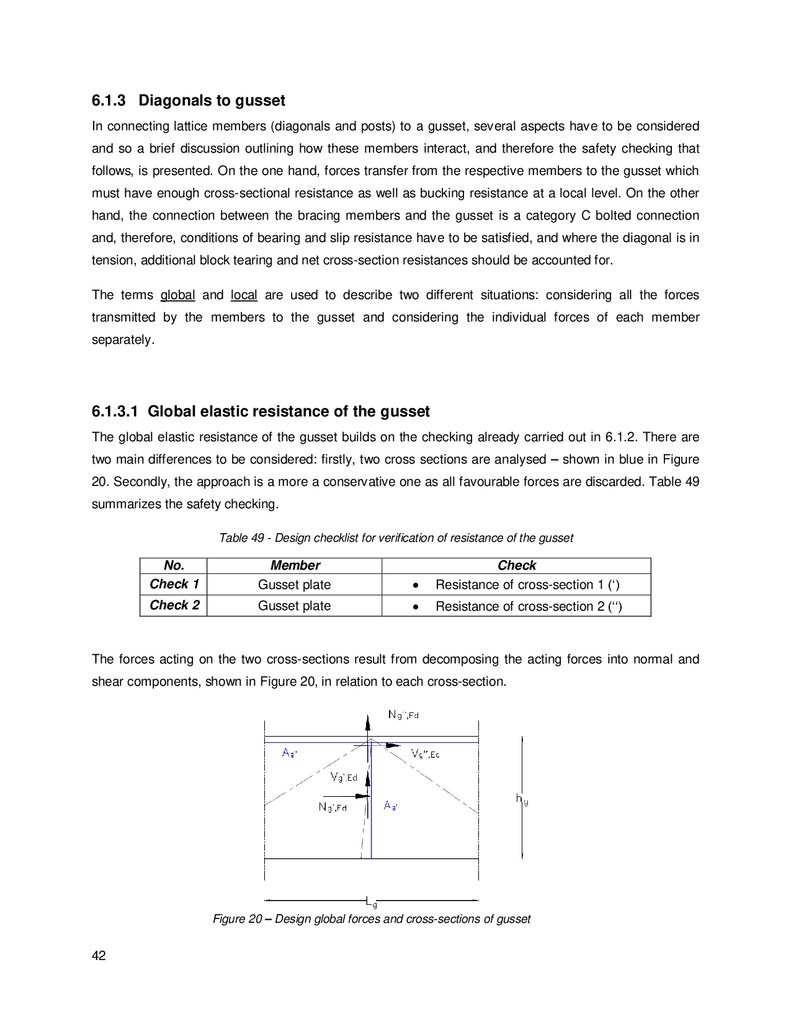
Figure 20 – Design global forces and cross-sections of gusset .......................................................... 42
Figure 21 - Positioning of bolts in diagonal 17 connecting to the gusset (dimensions in [mm]) ............ 45
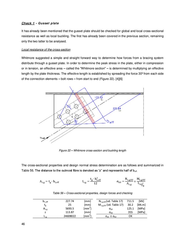
Figure 22 – Whitmore cross-section and buckling length ................................................................... 46
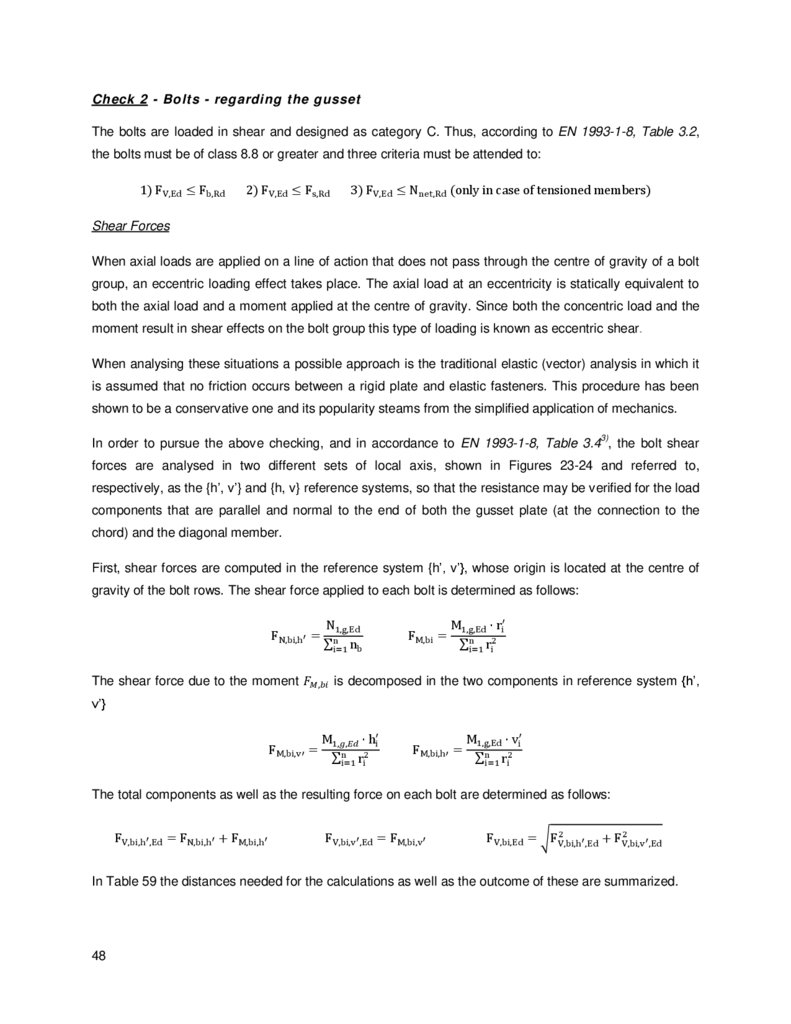
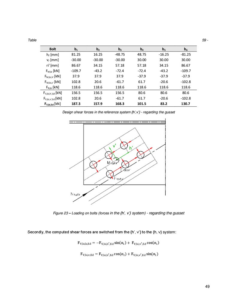
Figure 23 – Loading on bolts (forces in the {h’, v’} system) - regarding the gusset .............................. 49
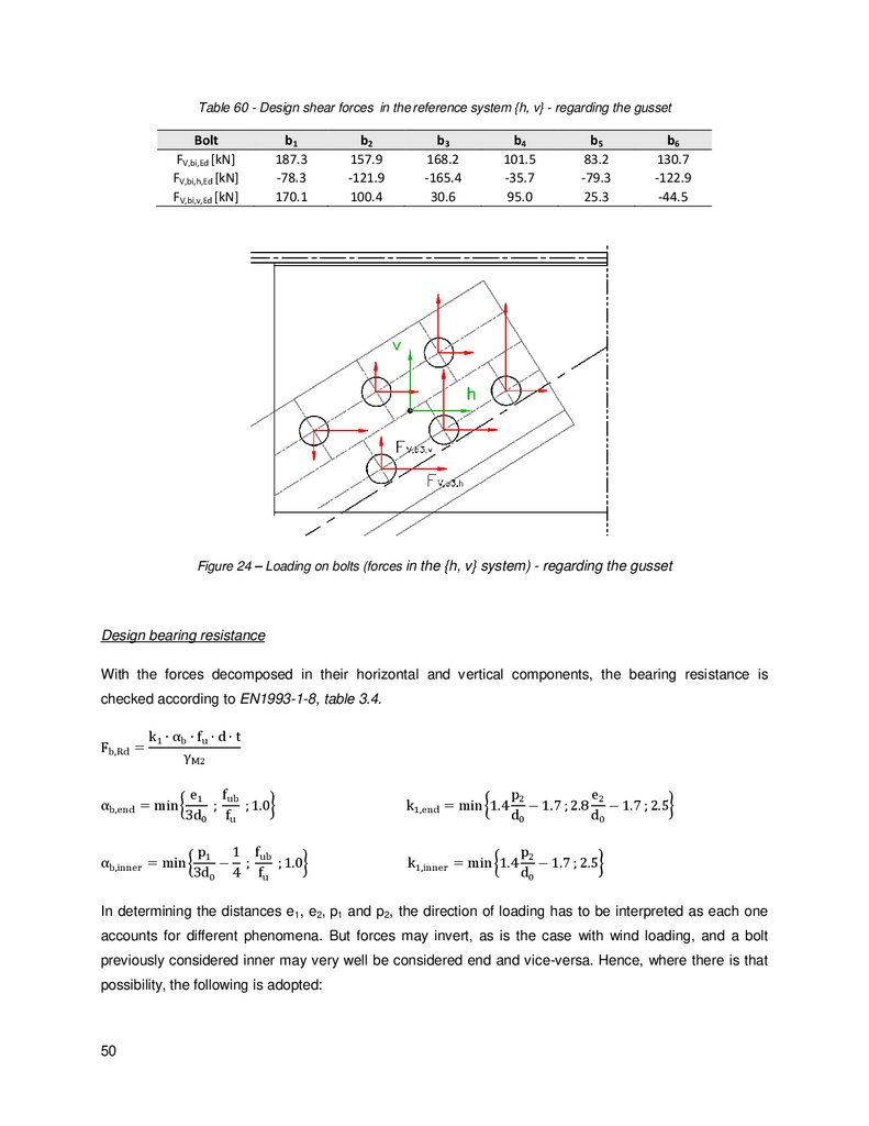
Figure 24 – Loading on bolts (forces in the {h, v} system) - regarding the gusset ............................... 50
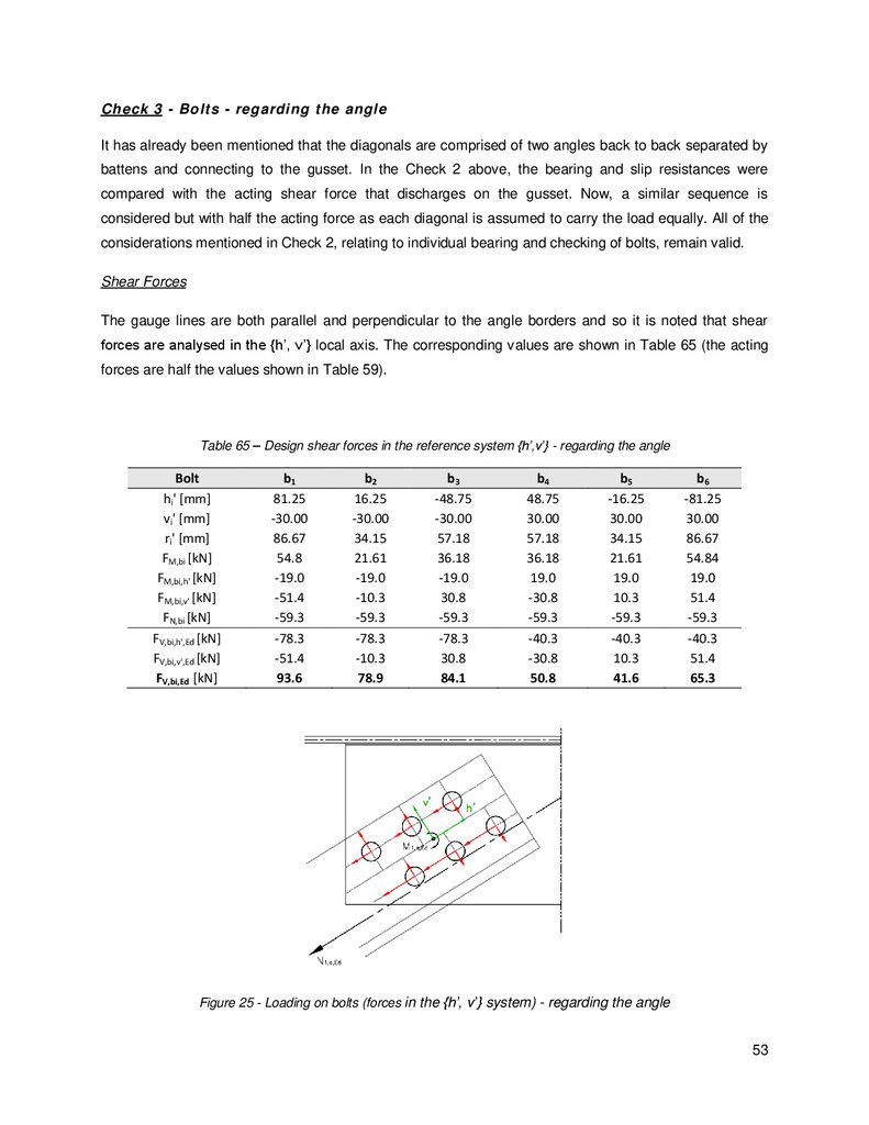
Figure 25 - Loading on bolts (forces in the {h’, v’} system) - regarding the angle ................................ 53
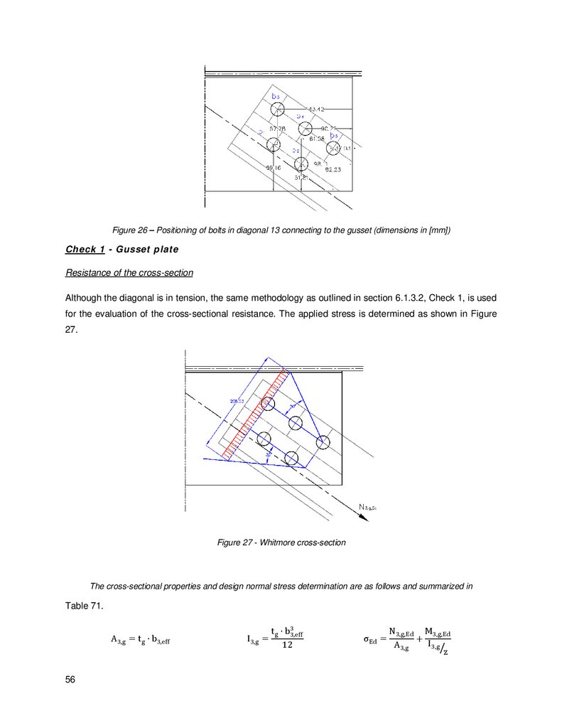
Figure 26 – Positioning of bolts in diagonal 13 connecting to the gusset (dimensions in [mm]) ........... 56
Figure 27 - Whitmore cross-section ................................................................................................... 56
Figure 28 - Loading on bolts (forces in the {h’, v’} system) - regarding the gusset .............................. 58
Figure 29 - Loading on bolts (forces in the {h, v} system) - regarding the gusset ................................ 58
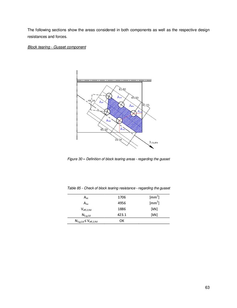
Figure 30 – Definition of block tearing areas - regarding the gusset ................................................... 63
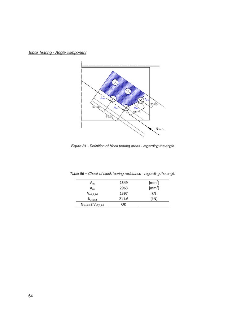
Figure 31 - Definition of block tearing areas - regarding the angle...................................................... 64
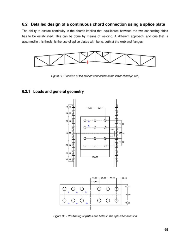
Figure 32- Location of the spliced connection in the lower chord (in red)............................................ 65
Figure 33 - Positioning of plates and holes in the spliced connection ................................................. 65
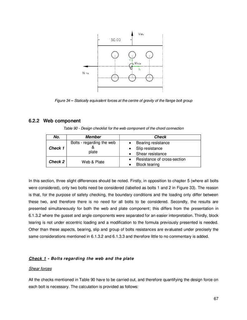
Figure 34 – Statically equivalent forces at the centre of gravity of the flange bolt group...................... 67
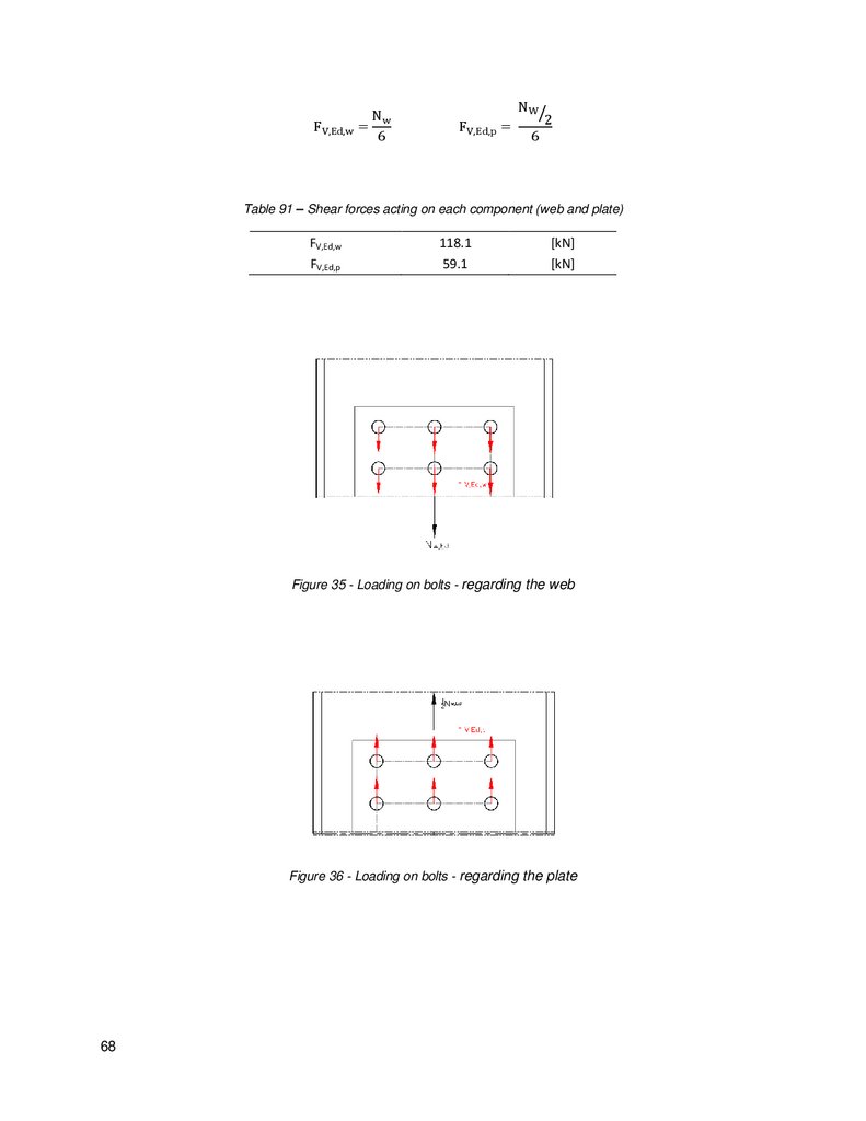
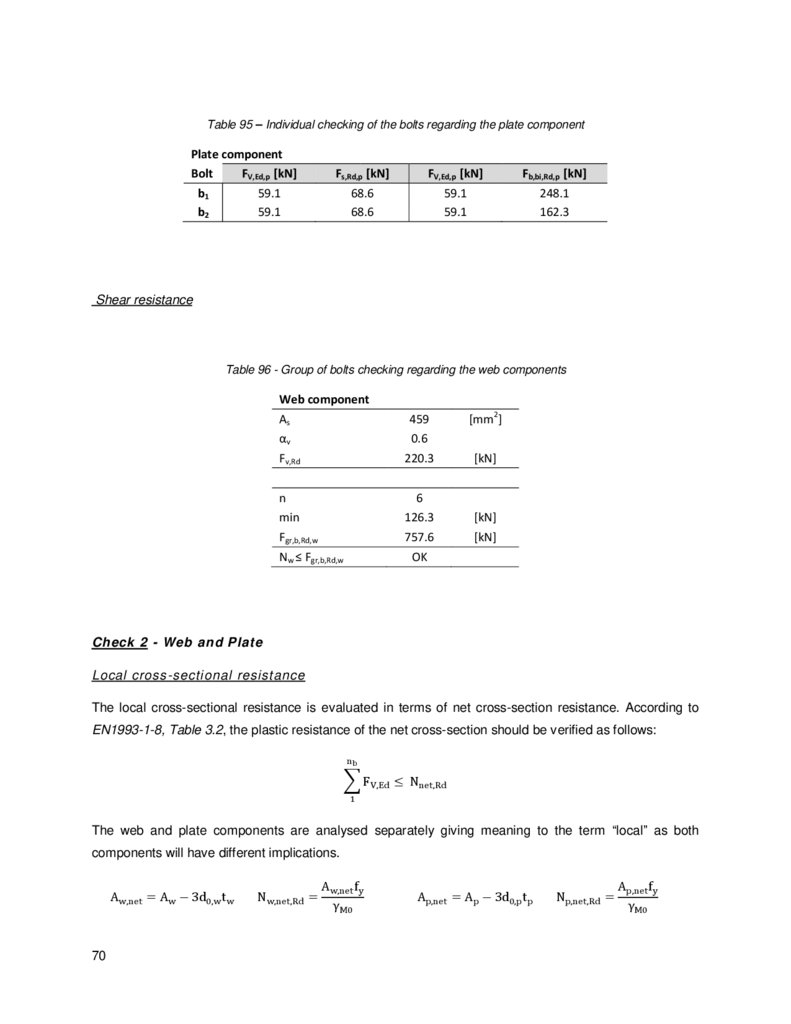
Figure 35 - Loading on bolts - regarding the web ............................................................................... 68
Figure 36 - Loading on bolts - regarding the plate.............................................................................. 68
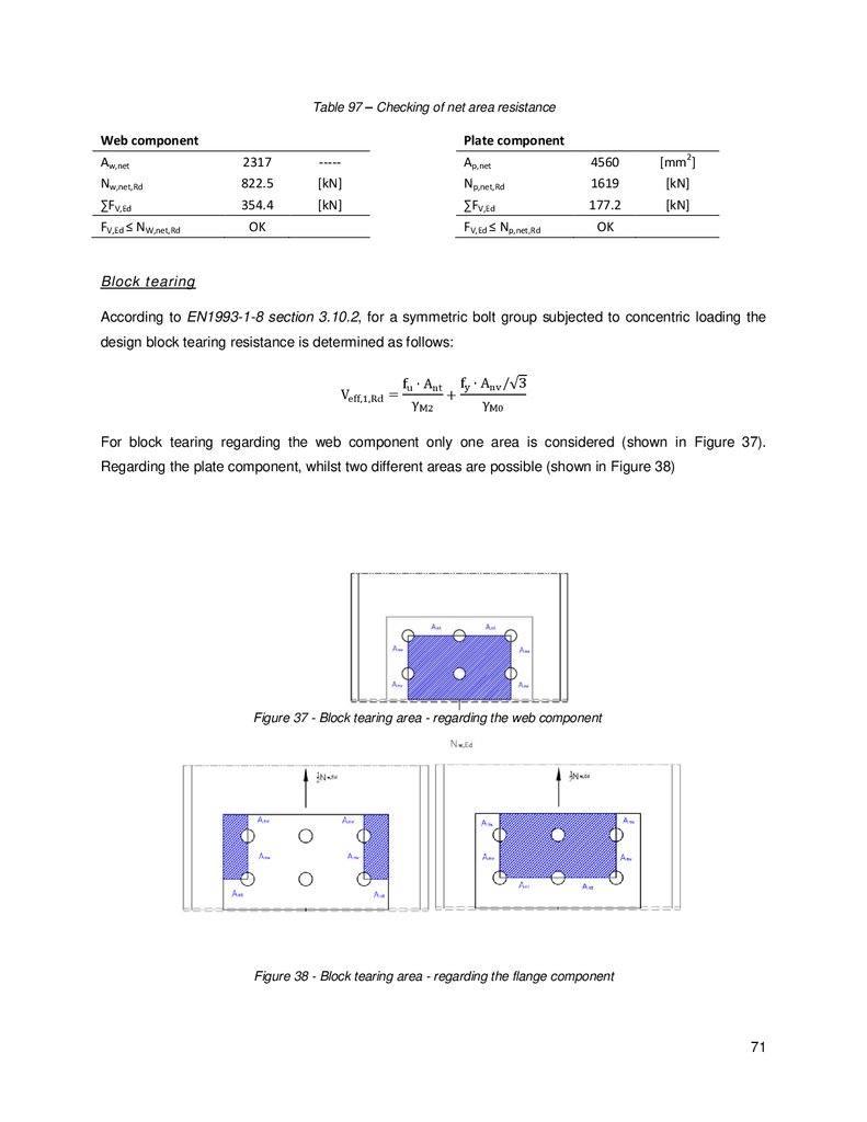
Figure 37 - Block tearing area - regarding the web component .......................................................... 71
ix
10.
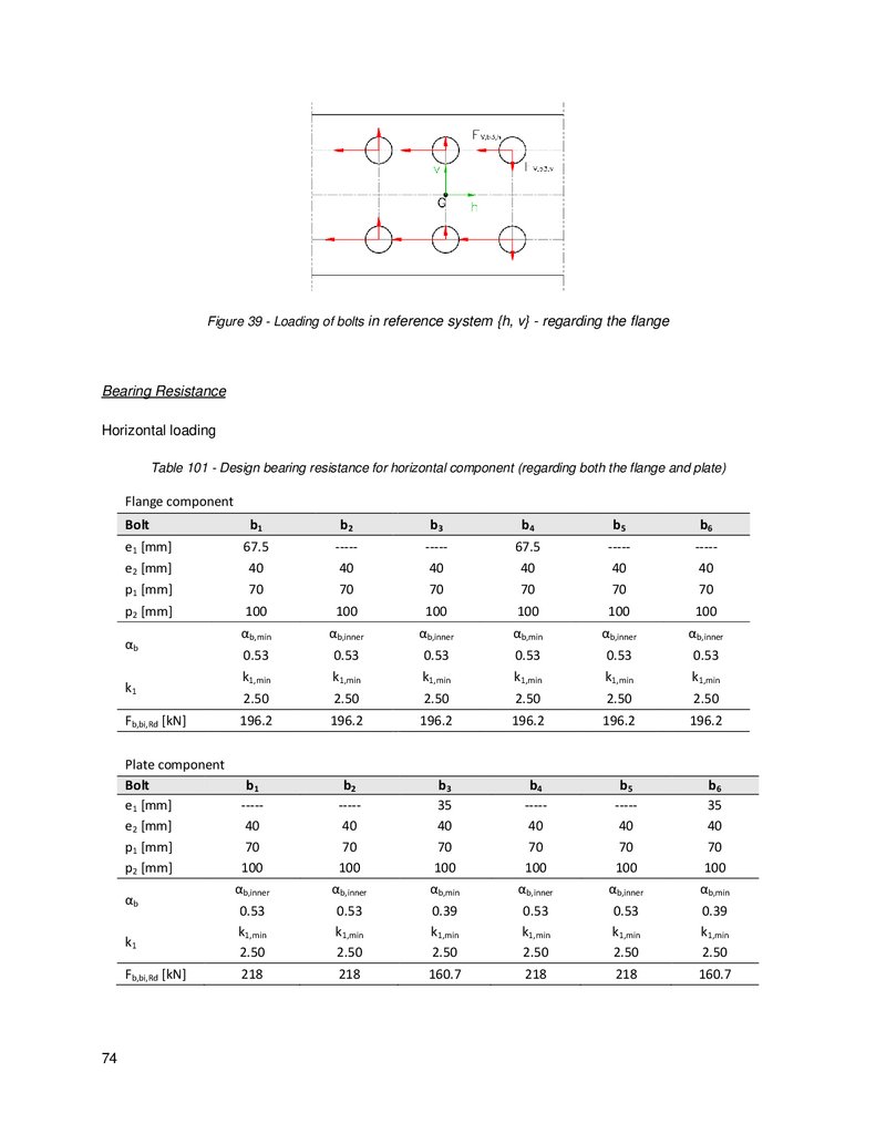
Figure 38 - Block tearing area - regarding the flange component ....................................................... 71Figure 39 - Loading of bolts in reference system {h, v} - regarding the flange..................................... 74
Figure 40 – Block tearing - regarding the flange ................................................................................ 77
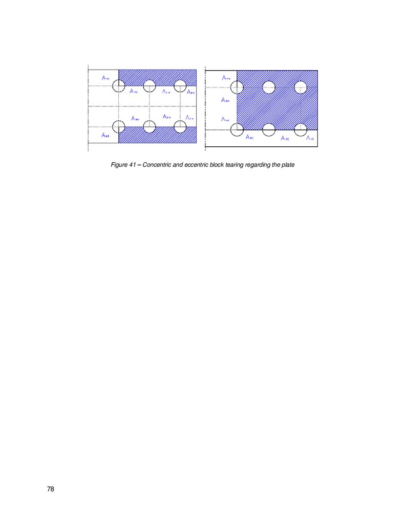
Figure 41 – Concentric and eccentric block tearing regarding the plate .............................................. 78
x
11.
List of TablesTable 1 – Considered steel properties .................................................................................................8
Table 2 – List of members of the roof structure ....................................................................................9
Table 3 – List of bolts used in the connections.....................................................................................9
Table 4 – Advantages of welded and bolted connections .....................................................................9
Table 5 – List of connections in the roof structure .............................................................................. 10
Table 6 – Live loads on roof category H ............................................................................................ 13
Table 7 – Evaluation of the characteristic snow load.......................................................................... 13
Table 8 – Evaluation of the characteristic wind pressure .................................................................... 14
Table 9 – Wind pressure (in kN/m2) for each zone of the roof, for wind direction θ=0º and 5º slope .... 14
2
Table 10 - Wind pressure [in kN/m ] for each zone of the roof, for wind direction θ=90º and 5º slope . 14
Table 11 – Summary of the partial factors for ULS............................................................................. 15
Table 12 – Summary of the partial factors for SLS (frequent combinations) ....................................... 15
Table 13 – Bending moment [in kN.m] comparison between rigid and pinned diagonals with different
chord layouts .................................................................................................................................... 18
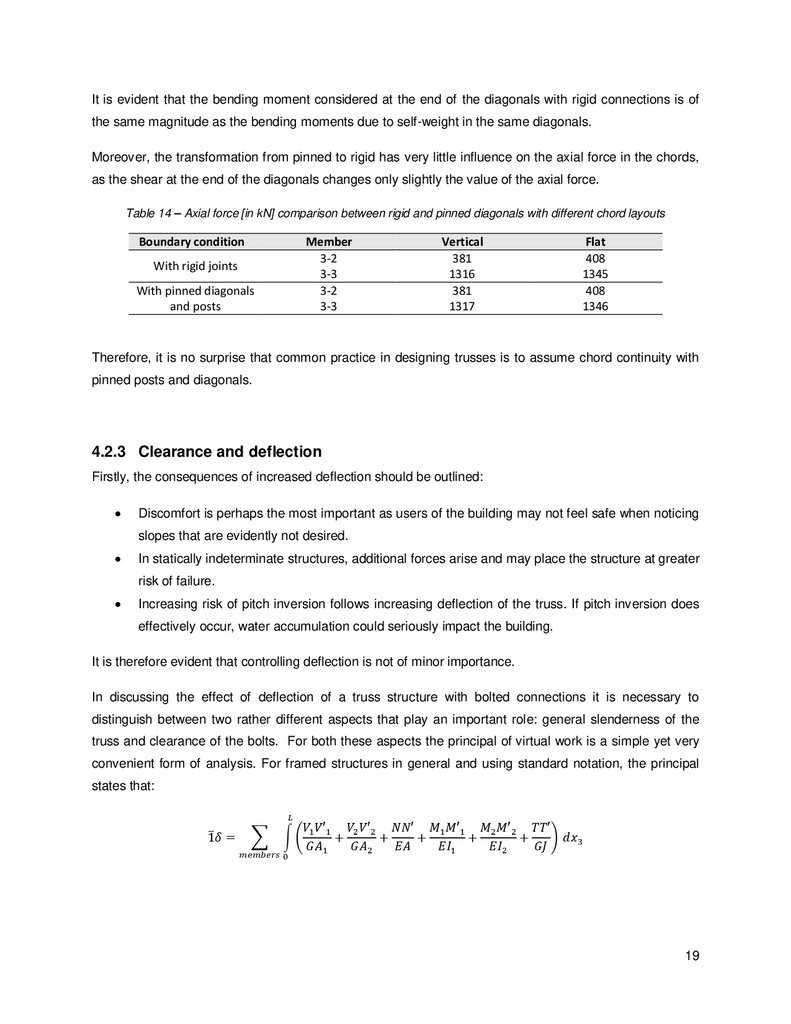
Table 14 – Axial force [in kN] comparison between rigid and pinned diagonals with different chord
layouts .............................................................................................................................................. 19
Table 15 – Axial forces due to the point load (for each pair of members, the sum of the axial forces is
presented) ........................................................................................................................................ 21
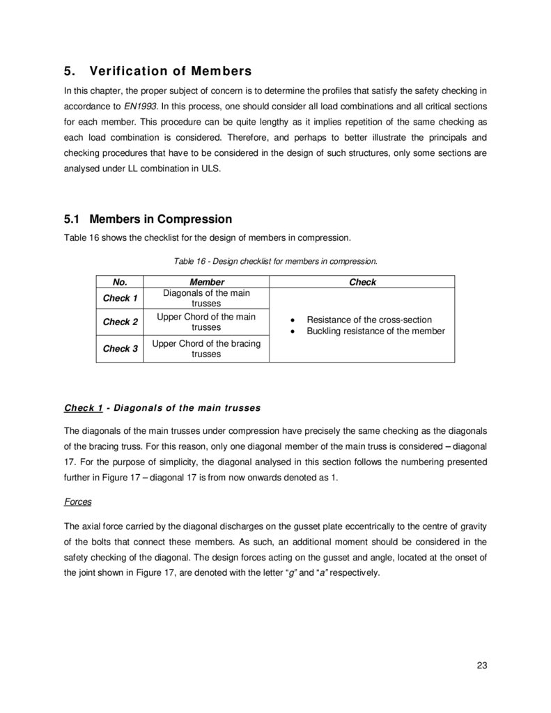
Table 16 - Design checklist for members in compression................................................................... 23
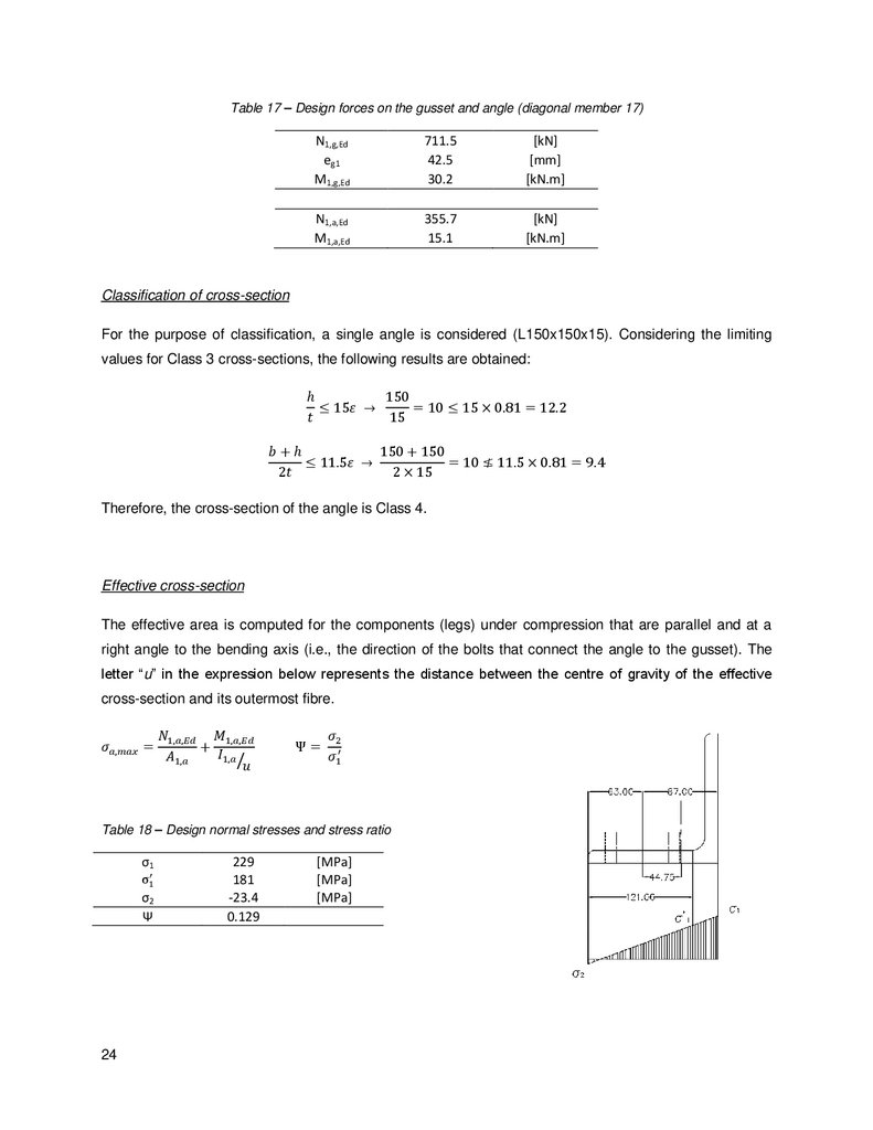
Table 17 – Design forces on the gusset and angle (diagonal member 17) ......................................... 24
Table 18 – Design normal stresses and stress ratio........................................................................... 24
Table 19 – Effective area relative to the parallel (outstanding) leg and perpendicular (internal) leg..... 25
Table 20 – Checking of cross-sectional resistance ............................................................................ 25
Table 21 – Checking of flexural buckling under uniform compression ................................................ 26
Table 22 – Buckling in between battens under uniform compression ................................................. 27
Table 23 – Verification of flexural buckling under uniform compression and bending.......................... 27
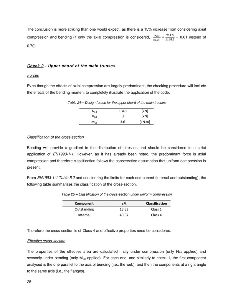
Table 24 – Design forces for the upper chord of the main trusses ...................................................... 28
Table 25 – Classification of the cross-section under uniform compression ......................................... 28
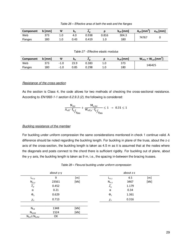
Table 26 – Effective area of both the web and the flanges ................................................................. 29
Table 27 - Effective elastic modulus .................................................................................................. 29
Table 28 – Flexural buckling under uniform compression................................................................... 29
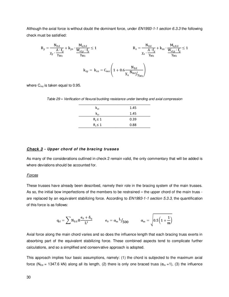
Table 29 – Verification of flexural buckling resistance under bending and axial compression ............. 30
Table 30 – Design forces for the upper chord of the bracing trusses .................................................. 31
Table 31 - Classification of the cross-section under uniform compression .......................................... 31
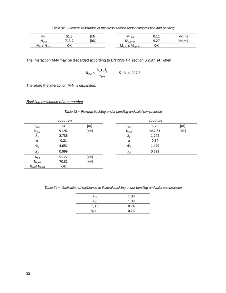
Table 32 – General resistance of the cross-section under compression and bending ......................... 32
Table 33 – Flexural buckling under bending and axial compression ................................................... 32
Table 34 – Verification of resistance to flexural buckling under bending and axial compression ......... 32
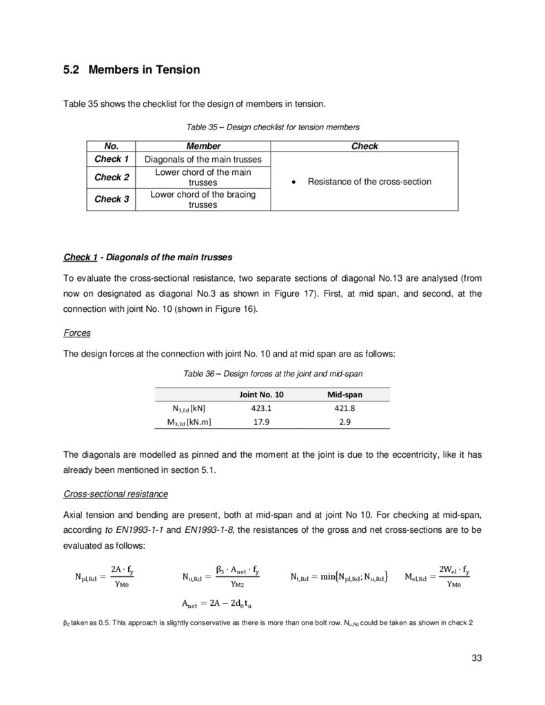
Table 35 – Design checklist for tension members .............................................................................. 33
xi
12.
Table 36 – Design forces at the joint and mid-span ........................................................................... 33Table 37 – Tension and bending resistance ...................................................................................... 34
Table 38 – Checking regarding the normal stress .............................................................................. 34
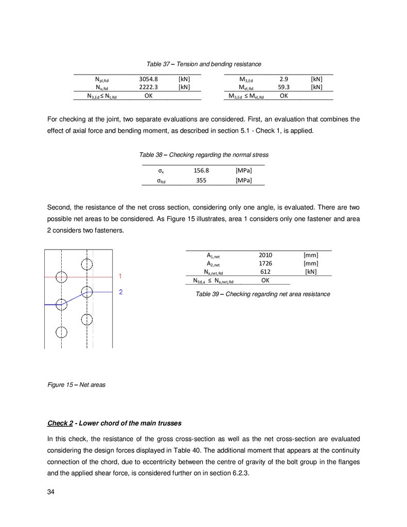
Table 39 – Checking regarding net area resistance ........................................................................... 34
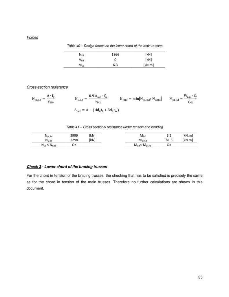
Table 40 – Design forces on the lower chord of the main trusses....................................................... 35
Table 41 – Cross sectional resistance under tension and bending ..................................................... 35
Table 42 – Internal forces at joint No 10 (LL combination in ULS) ...................................................... 37
Table 43 – Design forces on the bracing members - diagonals (1 and 3) and post (2) (Note: Positive
values correspond to tension forces) ................................................................................................. 38
Table 44 – Design checklist for gusset to chord connection ............................................................... 39
Table 45 – Design forces for checking of gusset to chord connection ................................................ 39
Table 46 – Properties of the plate cross-section and design value of normal and shear stresses ....... 40
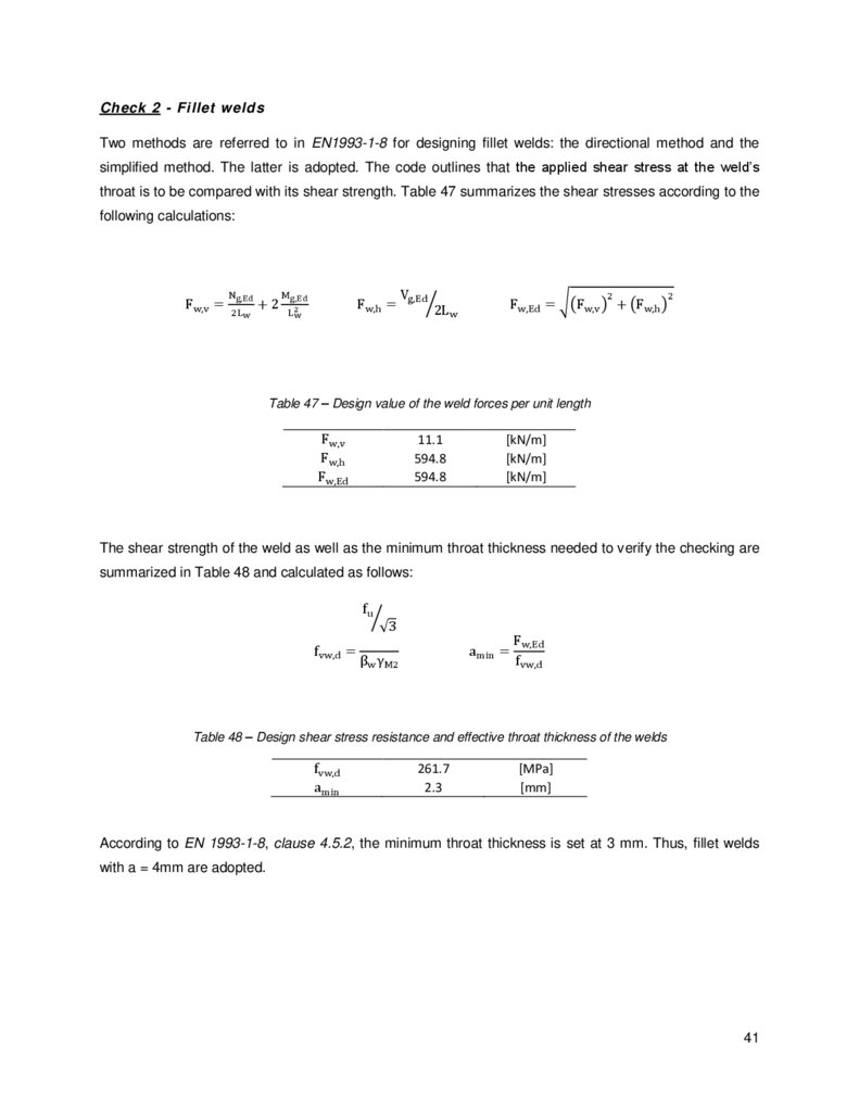
Table 47 – Design value of the weld forces per unit length ................................................................ 41
Table 48 – Design shear stress resistance and effective throat thickness of the welds ....................... 41
Table 49 - Design checklist for verification of resistance of the gusset ............................................... 42
Table 50 – Areas of the gusset cross-sections................................................................................... 43
Table 51 – Design shear force and checking on cross-section 1 (‘) .................................................... 43
Table 52 – Design normal force and checking on cross-section 1 (‘) .................................................. 43
Table 53 – Design shear force and checking on cross-section 2 (‘’) ................................................... 44
Table 54 – Design normal force and checking on cross-section 2 (‘’) ................................................. 44
Table 55 – Design checklist for connection of diagonal 17 to gusset .................................................. 45
Table 56 – Cross-sectional properties, design forces and checking ................................................... 46
Table 57 – Buckling length and moment of inertia about the weak axis .............................................. 47
Table 58 - Design normal forces and checking .................................................................................. 47
Table 59 - Design shear forces in the reference system {h’,v’} - regarding the gusset ........................ 49
Table 60 - Design shear forces in the reference system {h, v} - regarding the gusset......................... 50
Table 61 – Design bearing resistance, regarding the gusset, for the horizontal component ................ 51
Table 62 - Design bearing resistance, regarding the gusset, for the vertical component ..................... 51
Table 63 – Design slip resistance - regarding the gusset ................................................................... 52
Table 64 – Individual checking of the bolts (bearing and slip resistance - regarding the gusset) ......... 52
Table 65 – Design shear forces in the reference system {h’,v’} - regarding the angle ......................... 53
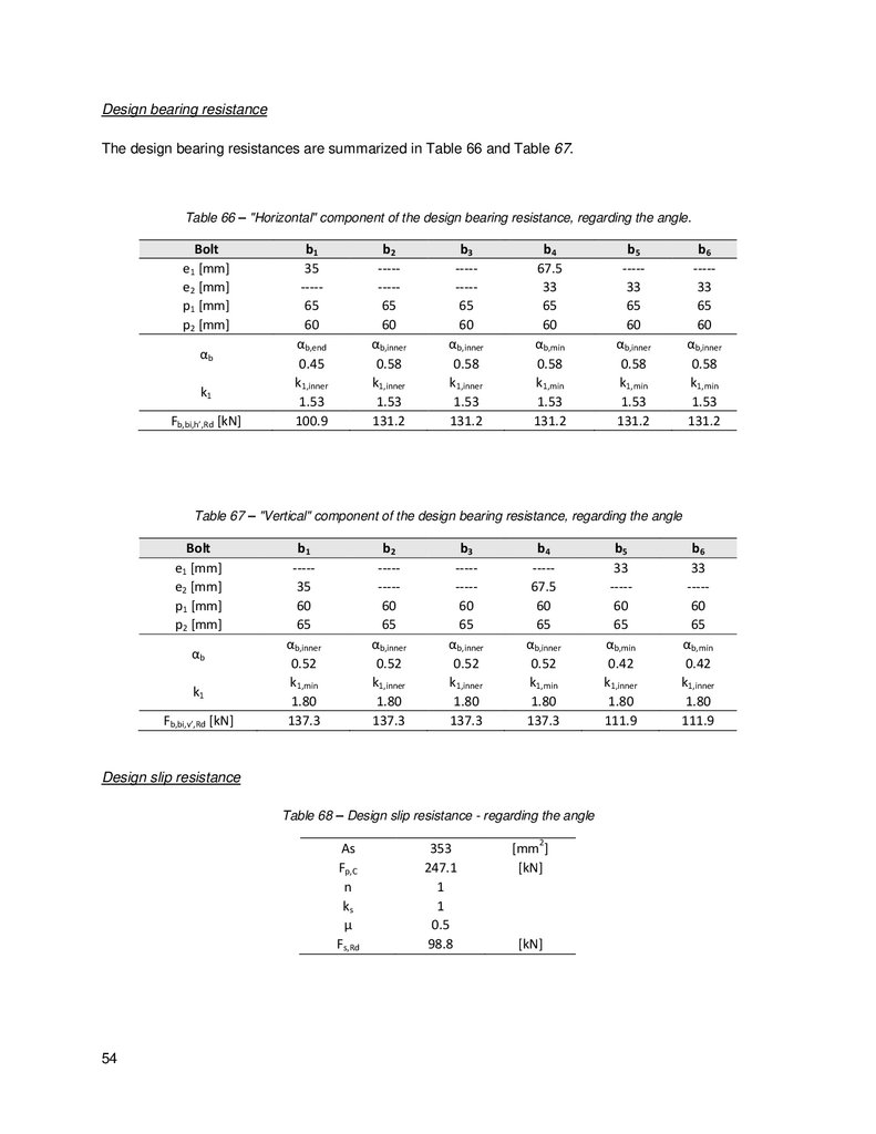
Table 66 – "Horizontal" component of the design bearing resistance, regarding the angle. ................ 54
Table 67 – "Vertical" component of the design bearing resistance, regarding the angle ..................... 54
Table 68 – Design slip resistance - regarding the angle ..................................................................... 54
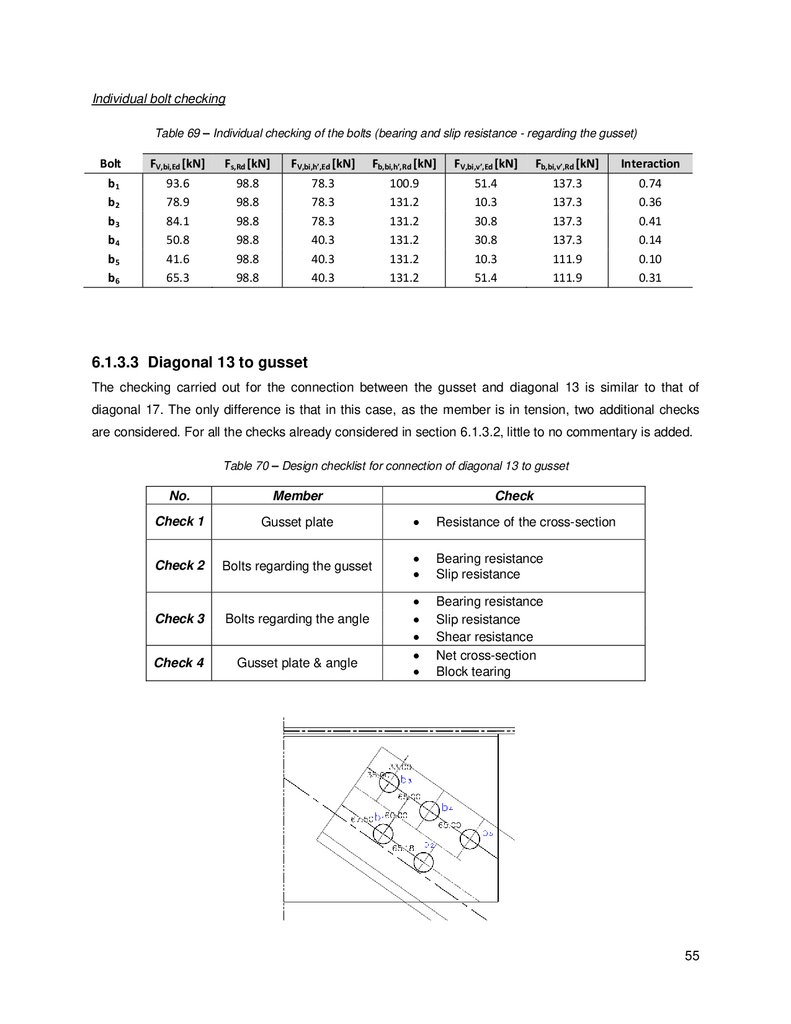
Table 69 – Individual checking of the bolts (bearing and slip resistance - regarding the gusset) ......... 55
Table 70 – Design checklist for connection of diagonal 13 to gusset .................................................. 55
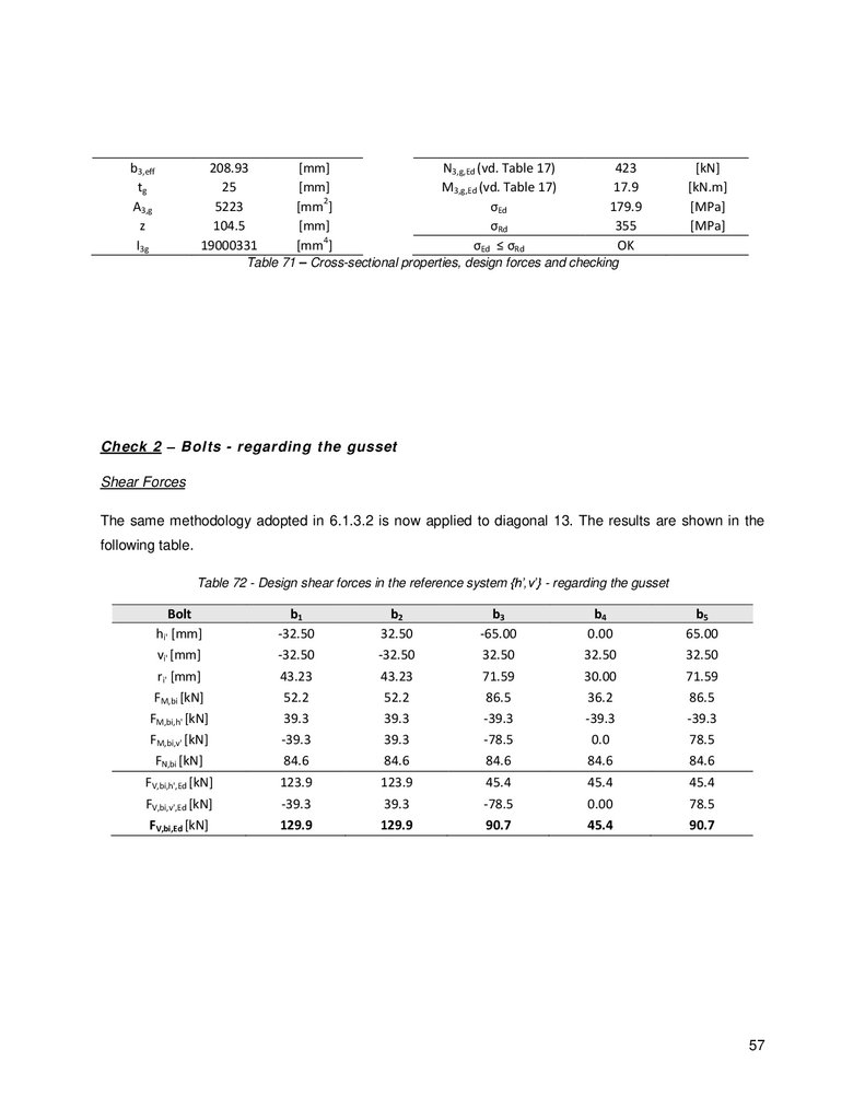
Table 71 – Cross-sectional properties, design forces and checking ................................................... 57
Table 72 - Design shear forces in the reference system {h’,v’} - regarding the gusset ........................ 57
Table 73 - Design shear forces in the reference system {h,v} - regarding the gusset .......................... 58
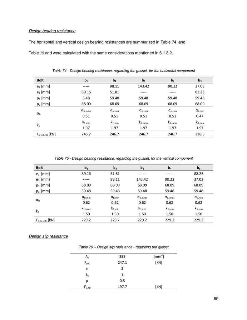
Table 74 - Design bearing resistance, regarding the gusset, for the horizontal component ................. 59
xii
13.
Table 75 - Design bearing resistance, regarding the gusset, for the vertical component ..................... 59Table 76 – Design slip resistance - regarding the gusset ................................................................... 59
Table 77 – Individual checking of the bolts (bearing and slip resistance - regarding the gusset) ......... 60
Table 78 – Design shear forces in the reference system {h’,v’} - regarding the angle ......................... 60
Table 79 – "Horizontal" component of the design bearing resistance, regarding the angle ................. 60
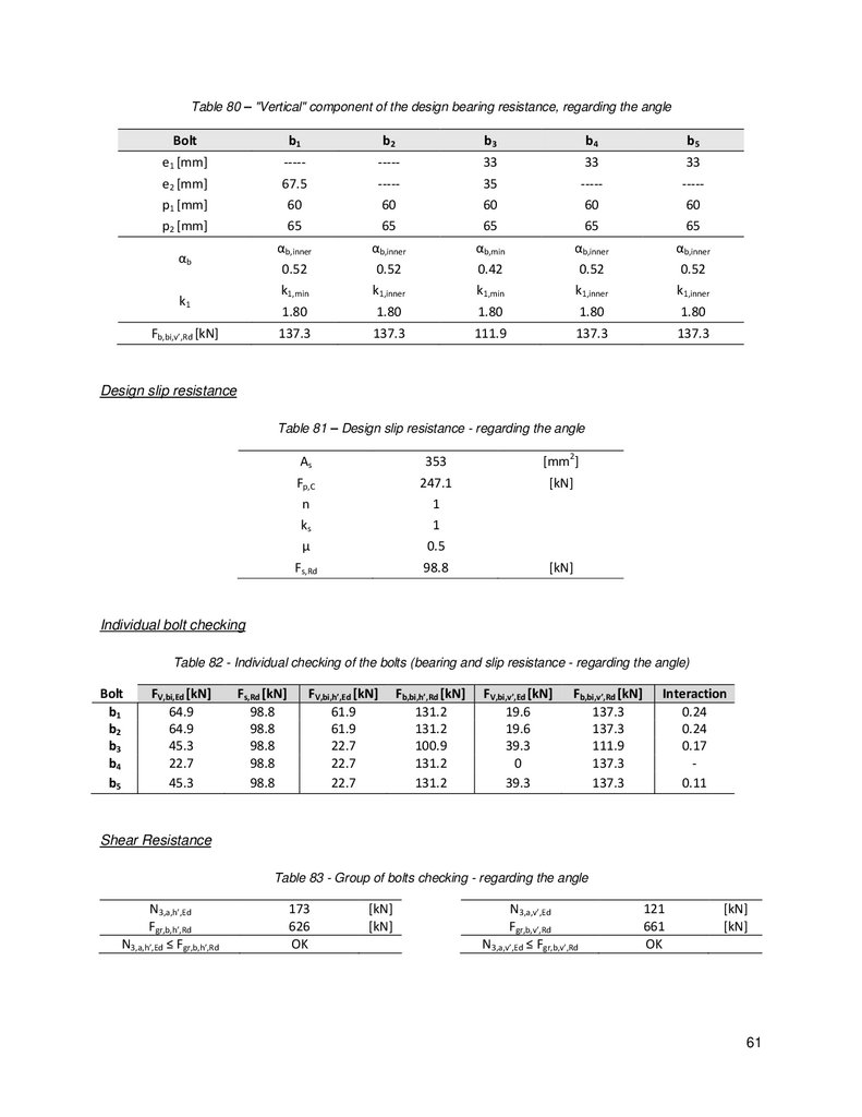
Table 80 – "Vertical" component of the design bearing resistance, regarding the angle ..................... 61
Table 81 – Design slip resistance - regarding the angle ..................................................................... 61
Table 82 - Individual checking of the bolts (bearing and slip resistance - regarding the angle)............ 61
Table 83 - Group of bolts checking - regarding the angle ................................................................... 61
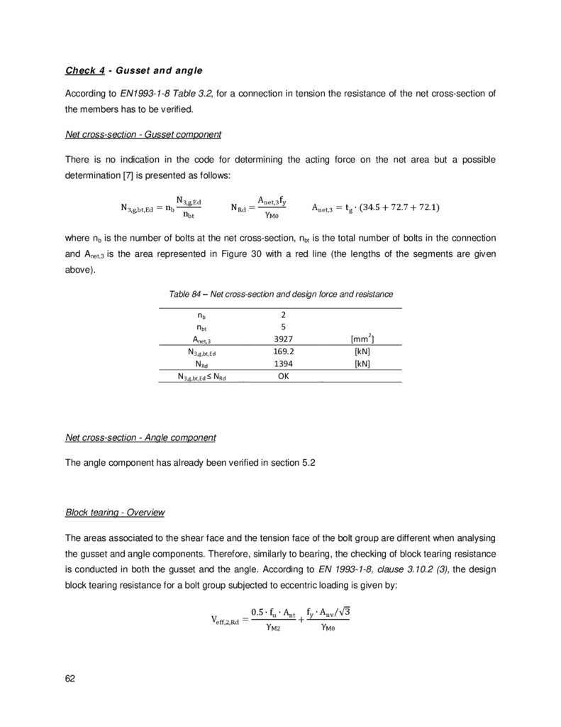
Table 84 – Net cross-section and design force and resistance........................................................... 62
Table 85 - Check of block tearing resistance - regarding the gusset .................................................. 63
Table 86 – Check of block tearing resistance - regarding the angle ................................................... 64
Table 87 – Design forces at the spliced connection ........................................................................... 66
Table 88 – Areas of the web and flange; eccentricity in flange ........................................................... 66
Table 89 – Internal forces on the web and flange .............................................................................. 66
Table 90 - Design checklist for the web component of the chord connection ...................................... 67
Table 91 – Shear forces acting on each component (web and plate) ................................................. 68
Table 92 – Design bearing resistances of the web and plate components .......................................... 69
Table 93 – Design slip resistance regarding the web and the plate .................................................... 69
Table 94 – Individual checking of the bolts regarding the web component ......................................... 69
Table 95 – Individual checking of the bolts regarding the plate component ........................................ 70
Table 96 - Group of bolts checking regarding the web components ................................................... 70
Table 97 – Checking of net area resistance ....................................................................................... 71
Table 98 - Check of block tearing resistance - regarding the web and plate ....................................... 72
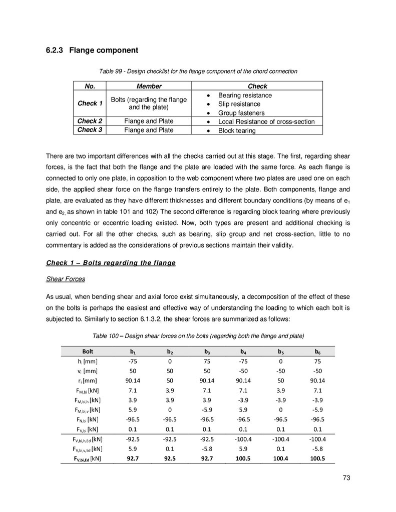
Table 99 - Design checklist for the flange component of the chord connection ................................... 73
Table 100 – Design shear forces on the bolts (regarding both the flange and plate) ........................... 73
Table 101 - Design bearing resistance for horizontal component (regarding both the flange and plate)
......................................................................................................................................................... 74
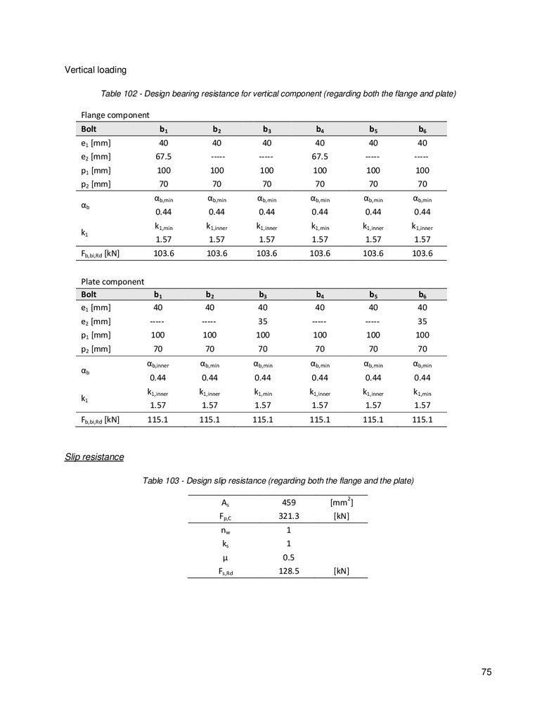
Table 102 - Design bearing resistance for vertical component (regarding both the flange and plate) .. 75
Table 103 - Design slip resistance (regarding both the flange and the plate) ...................................... 75
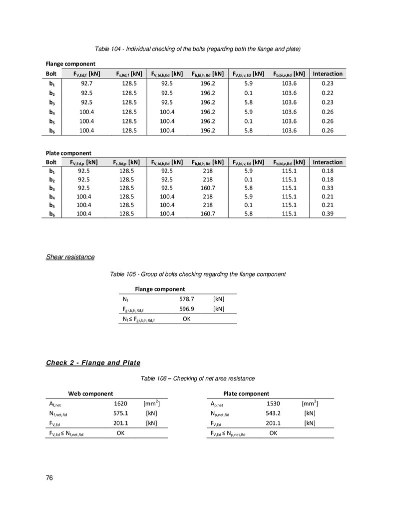
Table 104 - Individual checking of the bolts (regarding both the flange and plate) .............................. 76
Table 105 - Group of bolts checking regarding the flange component ................................................ 76
Table 106 – Checking of net area resistance ..................................................................................... 76
Table 107 – Block tearing resistance - regarding the flange (concentric loading)................................ 77
Table 108 – Checking of block tearing resistance - regarding the plate (concentric and eccentric
loading) ............................................................................................................................................. 77
xiii
14.
SymbolsChapter 3
A
gross cross-section area of bolts
d
nominal bolt diameter
d0
hole diameter for bolts
E
modulus of elasticity
fy
yield strength for structural steel
fu
ultimate strength for structural steel
fyb
yield strength for bolts
f ub
ultimate strength for bolts
G
shear modulus
Chapter 4
Cdir
directional factor
Ce
exposure coefficient
Cseason
season factor
Ct
thermal coefficient
Cz
coefficient (from NP EN 1991-1-3)
c0
orography factor
cr
roughness factor
Ed
design value of effect of actions
Gk
characteristic value of a permanent action
H
height of the roof above ground
Iv
turbulence intensity
kI
turbulence factor
kr
terrain factor
Qk
characteristic value of a concentrated load
qb
basic velocity pressure
qk
characteristic value of a uniformly distributed load
qp
peak velocity pressure
s
snow load on the roof
sk
characteristic value of snow load on the ground at the relevant site
vb
basic wind velocity
vb,0
fundamental value of the basic wind velocity
vm
mean wind velocity
z
height above ground
z0
roughness length
xiv
15.
z0,IIterrain category II
µ1
shape coefficient for snow loads
γg
partial factor for permanent action
γq
partial factor for variable action
ψ
factor for combination value of an action
Chapter 5
x-x
axis along a member
y-y
major axis of a cross-section
z-z
minor axis of a cross-section
v-v
minor axis of a cross-section (where this does not coincide with z-z)
Aa
area of the angle’s cross-section
Aeff
effective cross-section area
Anet
net area of angle
b,eff
effective width
Cay
equivalent uniform moment factor
Cmz
equivalent uniform moment factor
CmLT
equivalent uniform moment factor
e0
maximum amplitude of a member imperfection
eN
shift of the centroid of the effective area relative to the original center of gravity
Ia
moment of inertia of the angle about the relevant axis
kyy
interaction factor
kzy
interaction factor
kσ
buckling factor for plates
Lcr
buckling length
Ma,Ed
bending moment on the angle
Mg,Ed
bending moment on the gusset
Mpl,Rd
design plastic resistance to bending about the relevant axis
m
number of braced elements
Na,Ed
axial force on the angle
Nb,Rd
design buckling resistance of a compression member
Nc,Rd
design resistance of the net cross-section for uniform compression
Ncr
elastic critical force for the relevant buckling mode based on the gross cross section
Ng,Ed
axial force on the gusset
Npl,Rd
design plastic resistance to normal forces of the gross cross-section
Nt,Rd
design value of the resistance to tension force
Nu,Rd
design ultimate resistance to normal forces of the net cross-section
Qp
equivalent force
qd
equivalent force per unit length
Va,Ed
shear force on the angle
xv
16.
Vg,Edshear force on the gusset
W eff
effective elastic section modulus
σa
normal stress on the angle
σg
normal stress on the gusset
αm
reduction factor to assess the equivalent stabilizing load
γM0
partial factor for resistance of cross-sections whatever the class is
γM1
partial factor for buckling resistance of members
γM2
partial factor for resistance of cross-section in tension
Ψ
stress ratio
ϕi
value to determine the imperfection factor χ
λ̅i
non dimensional slenderness about the relevant axis
λ̅p
plate slenderness
ρ
reduction factor for plate buckling
χi
reduction factor about the relevant axis
Chapter 6
Af,net
net area in the flange component
Ag
area of the gusset’s cross section
Ann
net area subjected to shear
Ant
net area subjected to tension
Ap,net
net area in the plate component
Aw,net
net area in the web component
amin
minimum throat thickness
bi
number of the bolt
e1
end distance from the center of bolt hole to the adjacent end of any part
e2
edge distance from the center of bolt hole to the adjacent edge of any part
ef
eccentricity from the edge of the flange to the center of the bolt group
Fb,Rd
design bearing resistance per bolt
FM,bi
design shear force on each bolt due to the acting moment
FM,bi,h’
component along axis h’ of the design shear force on each bolt due to the acting moment
FM,bi,v’
component along axis v’ of the design shear force due on each bolt to the acting moment
FN,bi
design shear force on each bolt due to axial force on the gusset~
Fp,C
design value of pre-loading force
Fs,Rd
design slip resistance per bolt
FV,bi,Ed
design shear force on each bolt
FV,bi,h’,Ed
component along axis h’ of the design shear force on the gusset due to axial force
FV,bi,h,Ed
component along axis h of the design shear force on each bolt
FV,bi,v’,Ed
component along axis v’ of the design shear force on the gusset due to axial force
FV,hi,v,Ed
component along axis v of the design shear force on each bolt
FV,Rd
design shear resistance per bolt
xvi
17.
FV,Ed,wdesign shear force acting on the bolt group on the web
FV,Ed,p
design shear force acting on the bolt group on the flange
Fw
design value of the weld force per unit length
Fw,h
design value of the weld force per unit length, horizontal component
Fw,v
design value of the weld force per unit length, vertical component
f vw,d
design value of the shear strength of the weld
hi’
distance from the center of gravity of the bolt group to bolt bi along the axis h’
Ig
moment of inertia about the minor axis of the gusset cross section
K
Thornton factor
Mf
design bending moment acting on the flange of the chord in a spliced connection
Nf
design force acting on one flange of the chord in a spliced connection
Nf,net,Rd
design force acting on the net area of the flange component
Ni,g,bt,Ed
design acting normal force on the gusset.
Np,net,Rd
design force acting on the net area of the plate component
Nw
design force acting on the web of the chord in a spliced connection
Nw,net,Rd
design force acting on the net area of the web component
n
number of friction surfaces
nb
number of bolts resisting in a line of action for net cross-section
nbt
total number of bolts in a connection for net cross-section resistance
p1
spacing between the centers of bolts in a line in the direction of load transfer
p2
spacing perpendicular to the load transfer direction between adjacent lines of bolts
ri’
distance from the center of gravity of the bolt group to bolt bi
t
thickness of the plate
Veff,1,Rd
design block tearing resistance for a symmetric bolt group subjected to concentric loading
Veff,2,Rd
design block tearing resistance for a symmetric bolt group subjected to eccentric loading
Vf
design shear force acting on the flange of the chord in a spliced connection
vi’
distance from the center of gravity of the bolt group to bolt bi along the axis v’
zg
vertical distance from the centroid of gusset cross section to the outmost fiber
τg
elastic shear stress in the gusset cross section
µ
slip factor
xvii
18.
19.
1. Introduction1.1 General historical overview
In every structural engineer’s first course in statics the concepts needed to analyse statically determinate
structures are defined. Apart from the simply supported beam, the truss stands as the backbone of
structural engineering.
The concepts needed to analyse these structures were largely developed in the seventeenth and
eighteenth century by the likes of Galileo, Stevin, Newton, Varignon, Bernoulli, Euler, Lagrange and
others.
It was in France, during the nineteenth century, that advanced mathematical and scientific concepts
related with civil engineering began to be taught, to the Ingéniurs of Ecole des Ponts et Chaussées and
Ecole Polytechnique. One can find the first mathematical analyses of trusses in Navier’s 1826 “Résumé
de Leçons Données à L’Ecole des Ponts et Chaussées sur l’Appication de la Mécanique” [1]. Navier
determined the forces in simple statically determined trusses as well as in statically indeterminate trusses,
but it was the analogy between forces in beams and forces in chords that perhaps had the greatest
influence on the design of trusses. By noticing that trusses with parallel chords could be treated as beams
with stiffness proportional to the area of both chords multiplied by the distance between them, the
formulas of Navier greatly expanded design practices and were later incorporated in the 1830’s and
1840’s designs of American wooden truss bridges.
Indeed, engineers such as Stephen Long, William Howe, James Warren, Thomas Pratt and many others
greatly understood the teachings of Navier and successfully applied them both in timber and iron
structures. Further dissemination of Navier’s work in the United States is due to Dennis Mahan, who in
1837 published his textbook “An Elementary Course of Civil Engineering for Use of the Cadets of the
United States Military Academy” and states in the introduction that “the best counsel that the author could
give to every young engineer, is to place in his library every work of science to which Mr. Navier’s name is
in any way attached” [1].
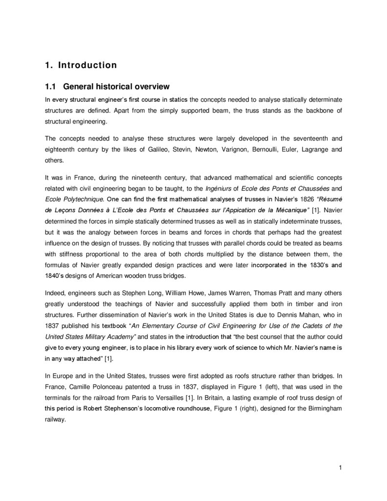
In Europe and in the United States, trusses were first adopted as roofs structure rather than bridges. In
France, Camille Polonceau patented a truss in 1837, displayed in Figure 1 (left), that was used in the
terminals for the railroad from Paris to Versailles [1]. In Britain, a lasting example of roof truss design of
this period is Robert Stephenson’s locomotive roundhouse, Figure 1 (right), designed for the Birmingham
railway.
1
20.
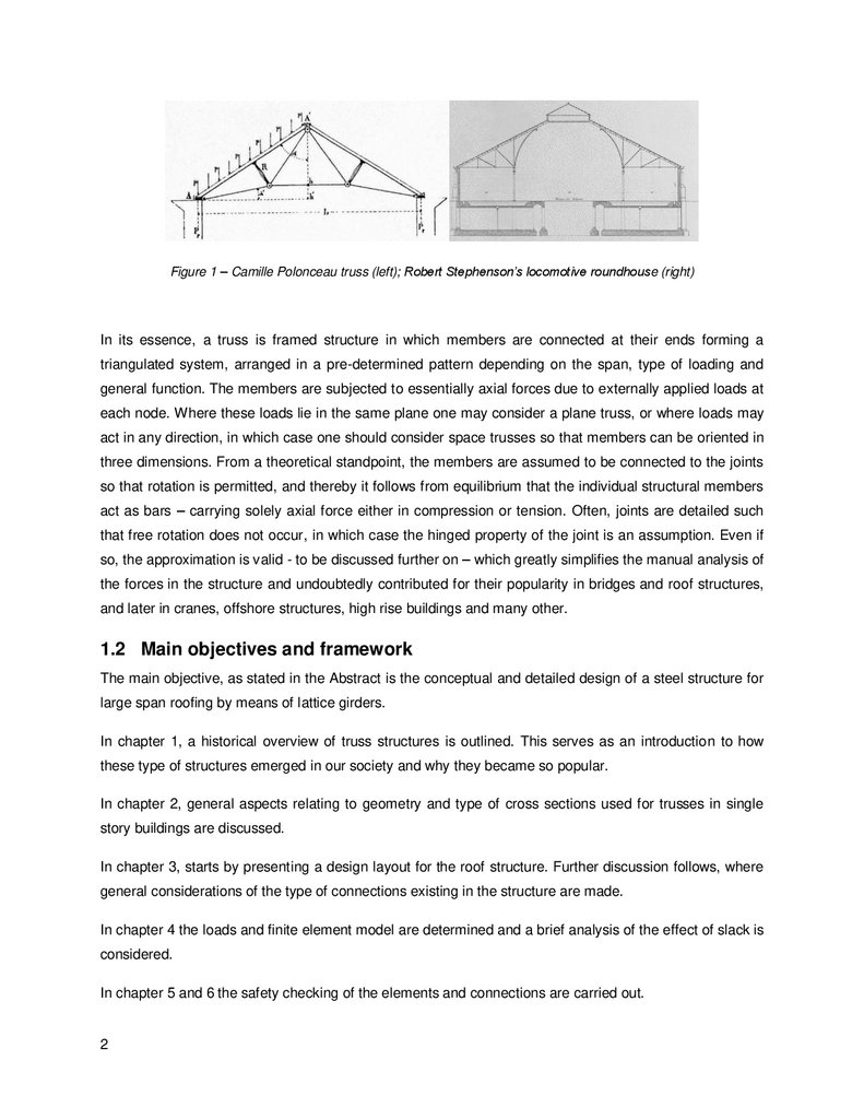
Figure 1 – Camille Polonceau truss (left); Robert Stephenson’s locomotive roundhouse (right)In its essence, a truss is framed structure in which members are connected at their ends forming a
triangulated system, arranged in a pre-determined pattern depending on the span, type of loading and
general function. The members are subjected to essentially axial forces due to externally applied loads at
each node. Where these loads lie in the same plane one may consider a plane truss, or where loads may
act in any direction, in which case one should consider space trusses so that members can be oriented in
three dimensions. From a theoretical standpoint, the members are assumed to be connected to the joints
so that rotation is permitted, and thereby it follows from equilibrium that the individual structural members
act as bars – carrying solely axial force either in compression or tension. Often, joints are detailed such
that free rotation does not occur, in which case the hinged property of the joint is an assumption. Even if
so, the approximation is valid - to be discussed further on – which greatly simplifies the manual analysis of
the forces in the structure and undoubtedly contributed for their popularity in bridges and roof structures,
and later in cranes, offshore structures, high rise buildings and many other.
1.2 Main objectives and framework
The main objective, as stated in the Abstract is the conceptual and detailed design of a steel structure for
large span roofing by means of lattice girders.
In chapter 1, a historical overview of truss structures is outlined. This serves as an introduction to how
these type of structures emerged in our society and why they became so popular.
In chapter 2, general aspects relating to geometry and type of cross sections used for trusses in single
story buildings are discussed.
In chapter 3, starts by presenting a design layout for the roof structure. Further discussion follows, where
general considerations of the type of connections existing in the structure are made.
In chapter 4 the loads and finite element model are determined and a brief analysis of the effect of slack is
considered.
In chapter 5 and 6 the safety checking of the elements and connections are carried out.
2
21.
2 Trusses in single story buildings2.1 Main functions
In single story buildings, namely industrial buildings, airplane hangars, sports pavilions, stadiums etc.,
trusses are usually used for two main purposes. First, to provide a path by which the loads (gravity, wind
etc.) can discharge on the columns. Second, to provide lateral stability to the series of portal trusses.
These are known as bracing trusses, which can be longitudinal or transverse to the series of portal
trusses; the bracing systems can be introduced on the roof and in the side walls such that the loads can
find a viable path to discharge at the foundation.
2.2 Truss layouts
There are many possible layouts for trusses in single story buildings. A short list is presented bellow
outlining the main attributes of each one.
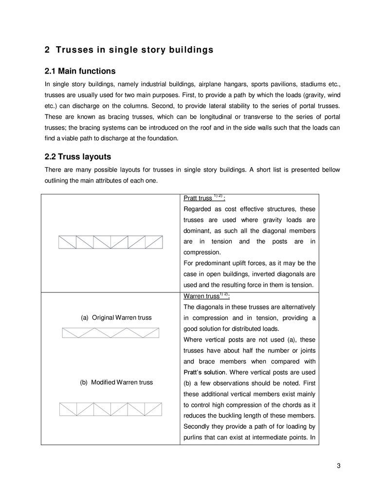
Pratt truss 1) 2) :
Regarded as cost effective structures, these
trusses are used where gravity loads are
dominant, as such all the diagonal members
are
in
tension
and
the
posts
are
in
compression.
For predominant uplift forces, as it may be the
case in open buildings, inverted diagonals are
used and the resulting force in them is tension.
Warren truss1) 2):
The diagonals in these trusses are alternatively
(a) Original Warren truss
in compression and in tension, providing a
good solution for distributed loads.
Where vertical posts are not used (a), these
trusses have about half the number or joints
and brace members when compared with
Pratt’s solution. Where vertical posts are used
(b) Modified Warren truss
(b) a few observations should be noted. First
these additional vertical members exist mainly
to control high compression of the chords as it
reduces the buckling length of these members.
Secondly they provide a path of for loading by
purlins that can exist at intermediate points. In
3
22.
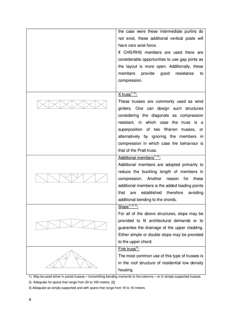
the case were these intermediate purlins donot exist, these additional vertical posts will
have zero axial force.
If CHS/RHS members are used there are
considerable opportunities to use gap joints as
the layout is more open. Additionally, these
members
provide
good
resistance
to
compression.
X truss1) 2):
These trusses are commonly used as wind
girders. One can design such structures
considering the diagonals as compression
resistant, in which case the truss is a
superposition of
two Warren trusses,
or
alternatively by ignoring the members in
compression in which case the behaviour is
that of the Pratt truss.
Additional members1) 2):
Additional members are adopted primarily to
reduce the buckling length of members in
compression.
Another
reason
for
these
additional members is the added loading points
that
are
established
therefore
avoiding
additional bending to the chords.
Slope1) 2) 3):
For all of the above structures, slope may be
provided to fit architectural demands or to
guarantee the drainage of the upper cladding.
Either simple or double slope may be provided
to the upper chord.
3)
Fink truss :
The most common use of this type of trusses is
in the roof structure of residential low density
housing.
1) May be used either in portal trusses – transmitting bending moments to the columns – or in simply supported trusses.
2) Adequate for spans that range from 20 to 100 meters. [3]
3) Adequate as simply supported and with spans that range from 10 to 15 meters.
4
23.
2.3 Roof structures2.3.1 General geometry
Focusing on roof structures, those that span more than 20 – 25 meters are often more economical if
designed as trusses instead of portal frames [2]. Savings stem from the fact that trusses are lighter, using
less steel, than solid profiles. Indeed, for the same weight, better performance in both of resistance and
stiffness is managed when considering trusses. Although aesthetics is a matter of taste, the general
consensus is that trusses are of a superior appearance when compared to portal frames. However,
relating to the installation process, hot rolled beams are less time consuming as they have much fewer
connections. For a cost effective truss, the engineer has to balance several aspects such as equipment,
man-hours, and cost of steel.
As with beams, the ratio depth to span of flat trusses at mid span, otherwise known as slenderness,
should range from 1/7.5 to 1/12 [2] so that good structural performance, regarding deflection and forces
on each element, is achieved. Moreover, efficient layouts should consider point loads applied only at
nodes with diagonals connecting with chords at 35º to 55º. The reason behind these two numbers is a
simple one. As the inclination of each diagonal increases (becoming more vertical) so will the number of
total diagonals in the truss. Thus, for the same loading, the axial force on each element will decrease
making the case for savings by means of a less robust cross-section. Evidently, the validity of this line of
thought breaks down when the total number of additional diagonals and connections result in such
additional cost that the savings in material are outweigh.
2.3.2 Cross-sections of members
There are two main families of cross-sections used in truss members: open sections and closed sections.
Open sections offer greater ease to establish connections as they require little to no welding, resorting
primarily to bolts. For small to intermediate spans, a popular design is using single angles for diagonals
and T profiles for chords. In this choice of design, it is recommended that vertical and diagonal members
be placed on the same side of the T section as to avoid additional bending of the web and twisting of the
chords [2]. For large spans and member forces, a popular design is using double angles or channels
back-to-back spaced intermediately with battens for the diagonal members and I or H profiles (i.e. IPE,
HEA, HEB) for the chords. The chords can be placed either vertically (standing up) or horizontally (flat). In
both layouts there are advantages to be noted. First, in the horizontal layout the obvious advantage is
that, for chords in compression, it is easier to increase in-plane buckling resistance, by shortening the
buckling length by means of additional diagonals, than to increase out-of-plane buckling resistance. In the
vertical orientation, the advantage stems from the fact that it is easier to establish a connection between
the purlins and chord.
5
24.
Closed sections have several advantages that need mentioning. Primarily, CHS and RHS sections aremuch more efficient cross-sections under compression when compared with open cross-sections. The
radius of gyration is the same in all directions, hence greater efficiency. They are considered to be more
aesthetic and are generally better appreciated by the public at large. As maintenance is regarded, tubular
trusses require less paint per linear meter [2], reducing the cost of the corrosion protection treatment
6
25.
3.Adopted solution
3.1 General overview
In deciding the appropriate layout of a roof structure the major problem is to find the right balance between
economy and structural efficiency. There is little difficulty in assuming a truss structure instead of a I
beam as it has already been noted that with increasing spans the latter become less efficient. Other
questions arise such as what is the ideal spacing of the main trusses? What is the best slope of the
chords and should both have the same slope? What is the best layout for the different truss? Is it
preferable to have transverse or longitudinal purlins? What is the best type of cross-section to adopt?
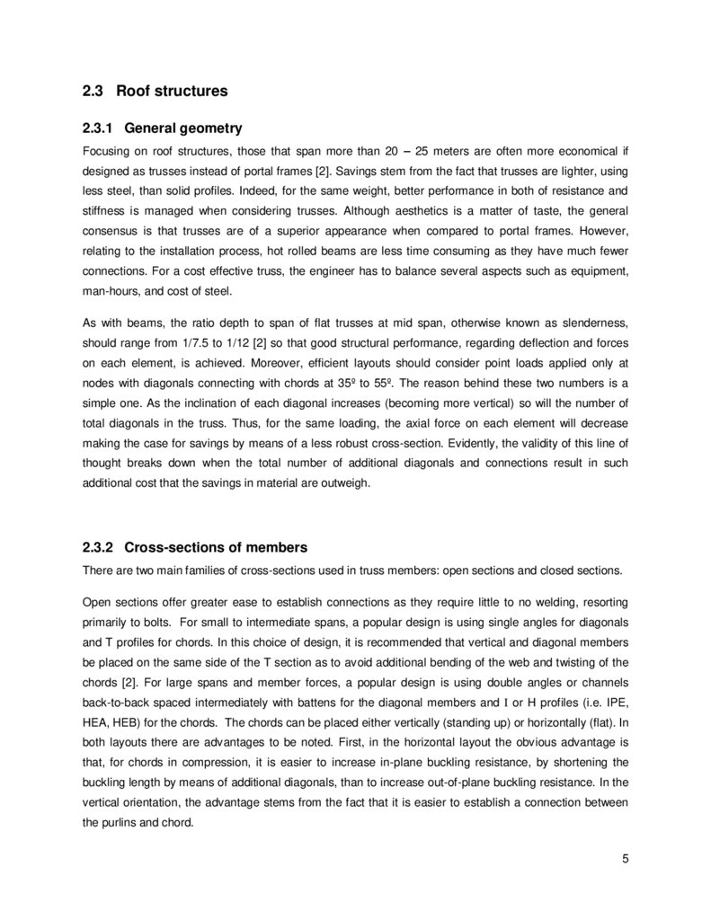
A solution is presented in this thesis, Figure 2, bearing the principles outlined in the previous section and
giving an answer to the issues mentioned above, although not in an exhaustive manner. The global
bracing system is not indicated in Figure 2 as it is not evaluated in the document. Figures 3 and 4 display
the layout of the main truss and bracing truss with the respective dimensions.
Purlins are separated at 1.75 m
14 m
36 m
Purlins (blue); Bracing truss (red); Main truss (black)
Figure 2 – General layout of the roof structure
7
26.
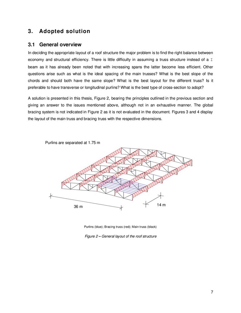
Figure 3 – Main truss and member numberingFigure 4 – Layout of the bracing truss (upper) and main truss (lower); (Dimensions in [m])
3.2 Members and materials
All structural steel members, including gusset plates, have the same grade of steel.
Table 1 – Considered steel properties
Members
Structural Steel
Type
S 355
fy [Mpa]
355
fu [Mpa]
510
E [Gpa]
210
G [Gpa]
81
The members that make up the structure are summarized in Table 2. As is shown in the table, all the
diagonals of the bracing truss have the same profile and the same is true for the main truss. The main
reason for this decision is to reduce the complexity of the installation on-site. It would be possible to adjust
the robustness of the profiles according to the internal forces but so has not been done.
8
27.
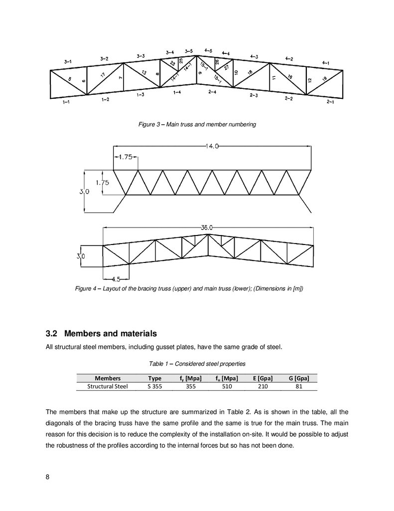
Table 2 – List of members of the roof structureStructure
Cladding
Purlins
Bracing truss
Main truss
Members
Upper & Lower chord
Diagonals
Upper chord
Lower chord
Diagonals
Profile
TR 45.333.1000 Negative
IPE 160 (vertical)
IPE 160 (Flat)
L 100x100x10
IPE 600 (Flat)
IPE 400 (Flat)
2L 150x150x15
The connections are established by welding and bolting. For the latter, depending on where the
connection is, several types of bolts are adopted so to best fit the needed resistance.
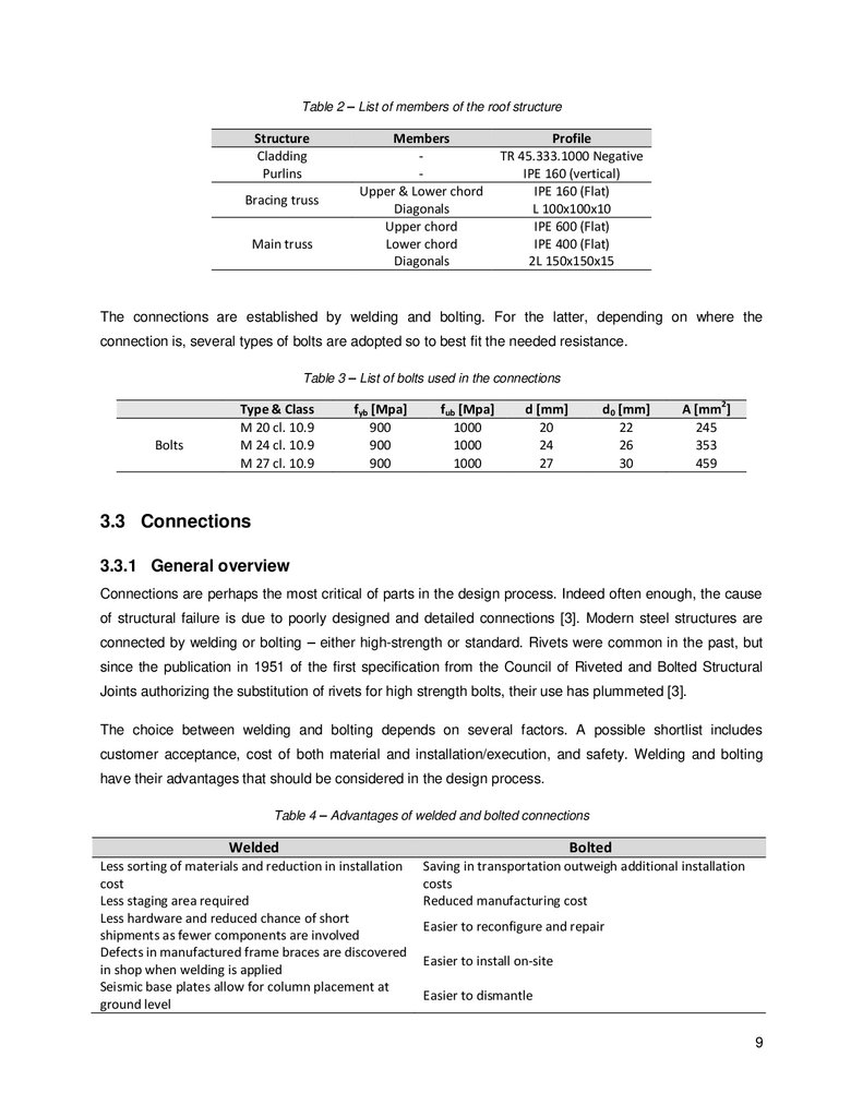
Table 3 – List of bolts used in the connections
Bolts
Type & Class
M 20 cl. 10.9
M 24 cl. 10.9
M 27 cl. 10.9
fyb [Mpa]
900
900
900
fub [Mpa]
1000
1000
1000
d [mm]
20
24
27
d0 [mm]
22
26
30
A [mm2]
245
353
459
3.3 Connections
3.3.1 General overview
Connections are perhaps the most critical of parts in the design process. Indeed often enough, the cause
of structural failure is due to poorly designed and detailed connections [3]. Modern steel structures are
connected by welding or bolting – either high-strength or standard. Rivets were common in the past, but
since the publication in 1951 of the first specification from the Council of Riveted and Bolted Structural
Joints authorizing the substitution of rivets for high strength bolts, their use has plummeted [3].
The choice between welding and bolting depends on several factors. A possible shortlist includes
customer acceptance, cost of both material and installation/execution, and safety. Welding and bolting
have their advantages that should be considered in the design process.
Table 4 – Advantages of welded and bolted connections
Welded
Bolted
Less sorting of materials and reduction in installation
cost
Less staging area required
Less hardware and reduced chance of short
shipments as fewer components are involved
Defects in manufactured frame braces are discovered
in shop when welding is applied
Seismic base plates allow for column placement at
ground level
Saving in transportation outweigh additional installation
costs
Reduced manufacturing cost
Easier to reconfigure and repair
Easier to install on-site
Easier to dismantle
9
28.
The adopted structural design has several types of connections, these can be summarized as follows:Table 5 – List of connections in the roof structure
Connecting members
Purlin to bracing truss
Chord continuity in both the bracing and main truss
Gusset to Chord
Diagonals to Gusset
Main truss to columns
Type
Bolted and welded
Spliced plate with bolts
Welded
Bolted
Bolted
Despite the interest in analysing all of the above, only the continuity chord connection, gusset to chord
and diagonals to gusset will be fully analysed in this document. Although not fully analysed, a brief
discussion on particular aspect of the connection of the main truss to the columns follows.
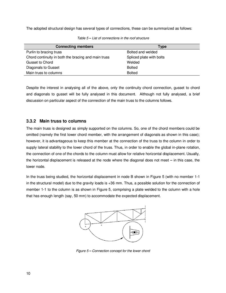
3.3.2 Main truss to columns
The main truss is designed as simply supported on the columns. So, one of the chord members could be
omitted (namely the first lower chord member, with the arrangement of diagonals as shown in this case);
however, it is advantageous to keep this member at the connection of the truss to the column in order to
supply lateral stability to the lower chord of the truss. Thus, in order to enable the global in-plane rotation,
the connection of one of the chords to the column must allow for relative horizontal displacement. Usually,
the horizontal displacement is released at the node where the diagonal does not meet – in this case, the
lower node.
In the truss being studied, the horizontal displacement in node B shown in Figure 5 (with no member 1-1
in the structural model) due to the gravity loads is +36 mm. Thus, a possible solution for the connection of
member 1-1 to the column is as shown in Figure 5, comprising a plate welded to the column with a hole
that has enough length (say, 50 mm) to accommodate the expected displacement.
Figure 5 – Connection concept for the lower chord
10
29.
3.3.3 Continuity of the chordsWhen designing large spans, one has to consider the maximum length of the members provided by the
fabricator. These typically limit the length at about 12 meters due to the nature of the transportation
method – trucking has limited allowable length, therefore limiting the length of profiles to be transported.
The proposed structure has a 36 meter span and therefore, in order to guaranty continuity, the connection
has to be rigid and there are several options that can be considered.
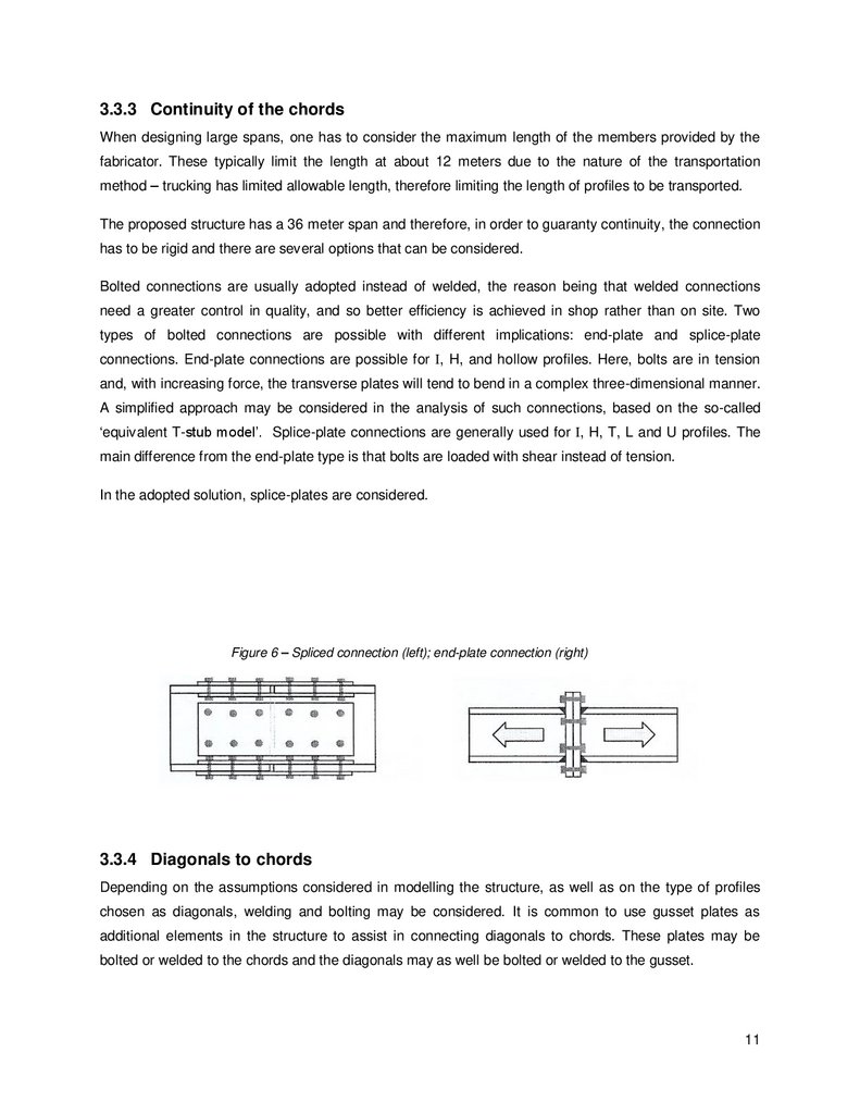
Bolted connections are usually adopted instead of welded, the reason being that welded connections
need a greater control in quality, and so better efficiency is achieved in shop rather than on site. Two
types of bolted connections are possible with different implications: end-plate and splice-plate
connections. End-plate connections are possible for I, H, and hollow profiles. Here, bolts are in tension
and, with increasing force, the transverse plates will tend to bend in a complex three-dimensional manner.
A simplified approach may be considered in the analysis of such connections, based on the so-called
‘equivalent T-stub model’. Splice-plate connections are generally used for I, H, T, L and U profiles. The
main difference from the end-plate type is that bolts are loaded with shear instead of tension.
In the adopted solution, splice-plates are considered.
Figure 6 – Spliced connection (left); end-plate connection (right)
3.3.4 Diagonals to chords
Depending on the assumptions considered in modelling the structure, as well as on the type of profiles
chosen as diagonals, welding and bolting may be considered. It is common to use gusset plates as
additional elements in the structure to assist in connecting diagonals to chords. These plates may be
bolted or welded to the chords and the diagonals may as well be bolted or welded to the gusset.
11
30.
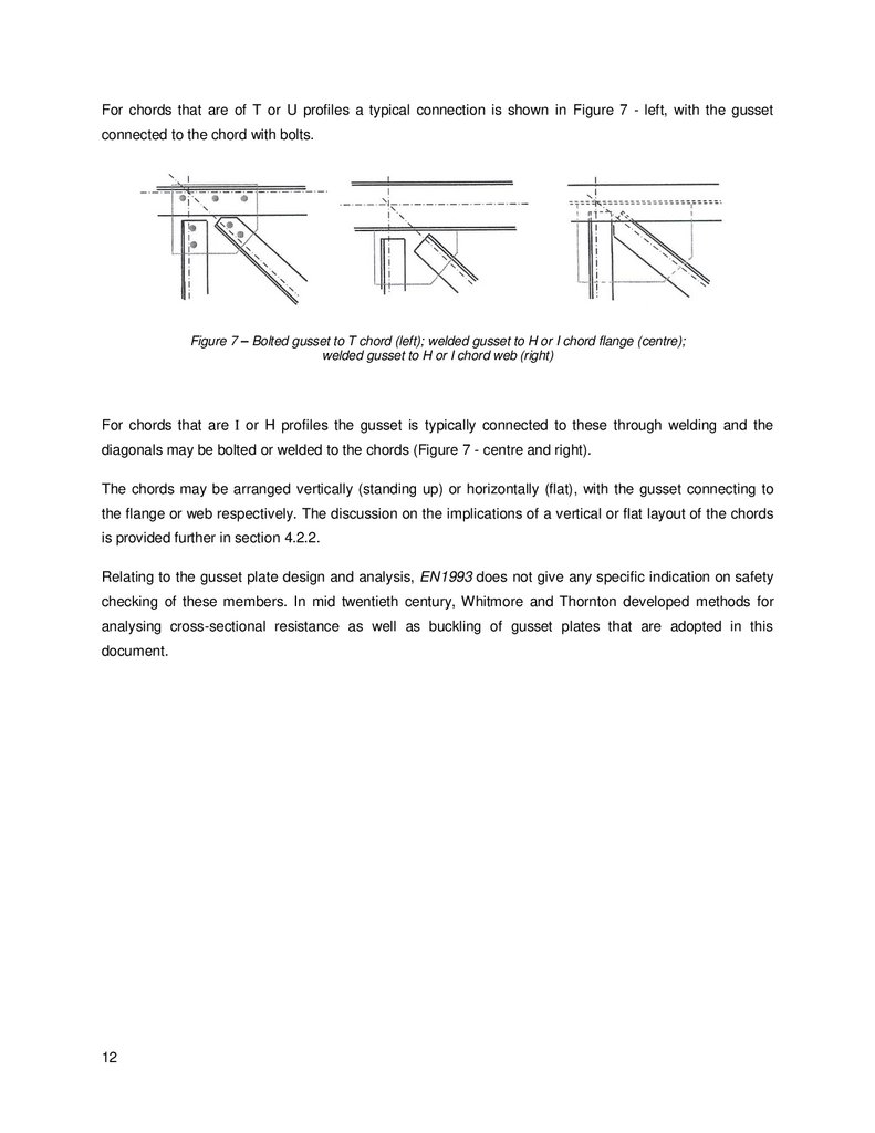
For chords that are of T or U profiles a typical connection is shown in Figure 7 - left, with the gussetconnected to the chord with bolts.
Figure 7 – Bolted gusset to T chord (left); welded gusset to H or I chord flange (centre);
welded gusset to H or I chord web (right)
For chords that are I or H profiles the gusset is typically connected to these through welding and the
diagonals may be bolted or welded to the chords (Figure 7 - centre and right).
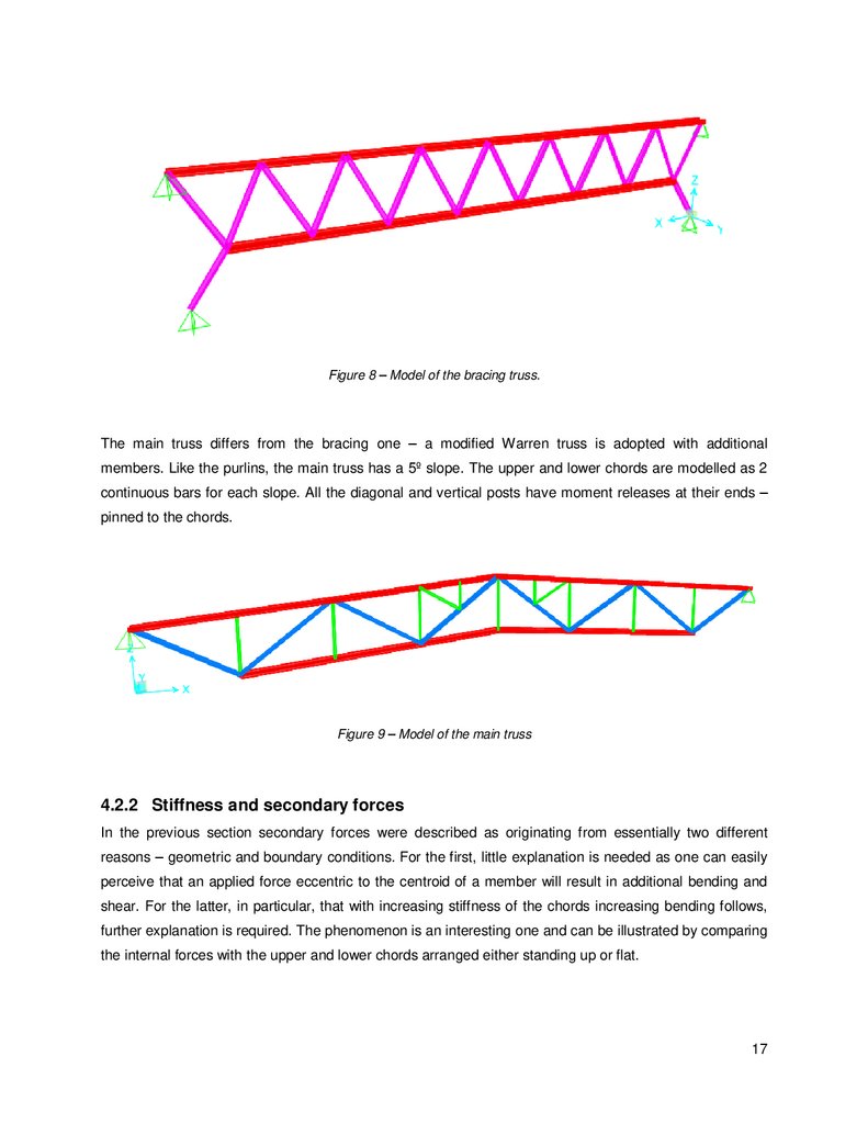
The chords may be arranged vertically (standing up) or horizontally (flat), with the gusset connecting to
the flange or web respectively. The discussion on the implications of a vertical or flat layout of the chords
is provided further in section 4.2.2.
Relating to the gusset plate design and analysis, EN1993 does not give any specific indication on safety
checking of these members. In mid twentieth century, Whitmore and Thornton developed methods for
analysing cross-sectional resistance as well as buckling of gusset plates that are adopted in this
document.
12
31.
4.Design Loads and Modelling
4.1 Loads
The only loads considered are the dead, live, wind and snow loads. Temperature has been opted out as
the structure is modelled as a series of 2D statically determinate structures with slotted holes in the
connections.
4.1.1 Dead Load (DL)
The main components of DL on roof trusses in single story industrial buildings are the self-weight of the
following elements: cladding, purlins, chords, diagonals and connection elements such as bolts and
gusset plates.
4.1.2 Live load (LL)
The gravity load due to maintenance is regarded as the main LL on roof trusses. In accordance to EN
1991-1-1, the roof is of category H and as such the characteristic value is defined in Table 6.
Table 6 – Live loads on roof category H
qk [kN/m2]
Qk [kN]
0.4
1
4.1.3 Snow load (SN)
Snow loads are quantified with the assumptions indicated in Table 7, according to NP EN 1991-1-3.
Table 7 – Evaluation of the characteristic snow load
s
ce
ct
µ1
2.24
1
1
0.8
[kN/m2]
sk
Cz
H
2.8
0.1
500
[kN/m2]
[m]
4.1.4 Wind load (WL)
Given the slope of 5º, and in accordance to EN 1991-1-4, the predominant wind load on the roof truss is
uplift force perpendicular to the roof, due to the suction effect of the wind blowing over. Hence, the wind
loads act contrary to gravity loads and with greater magnitude. To illustrate this result, Table 9 and Table
10 provide the design wind pressures in the roof (with the wind velocity and the division into zones
13
32.
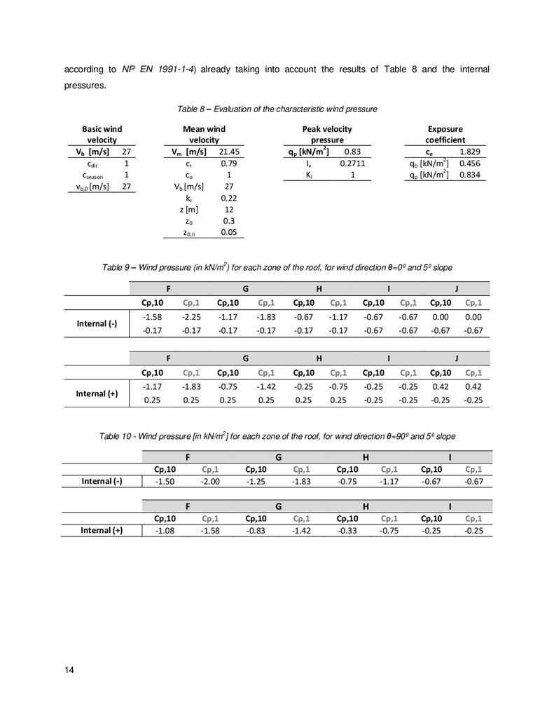
according to NP EN 1991-1-4) already taking into account the results of Table 8 and the internalpressures.
Table 8 – Evaluation of the characteristic wind pressure
Basic wind
velocity
Vb [m/s] 27
cdir
1
cseason
1
vb,0 [m/s] 27
Mean wind
velocity
Vm [m/s] 21.45
cr
0.79
co
1
Vb [m/s]
27
kr
0.22
z [m]
12
z0
0.3
z0,II
0.05
Peak velocity
pressure
qp [kN/m2]
0.83
Iv
0.2711
KI
1
Exposure
coefficient
ce
1.829
2
qb [kN/m ] 0.456
2
qp [kN/m ] 0.834
2
Table 9 – Wind pressure (in kN/m ) for each zone of the roof, for wind direction θ=0º and 5º slope
F
Internal (-)
G
I
J
Cp,10
Cp,1
Cp,10
Cp,1
Cp,10
Cp,1
Cp,10
Cp,1
Cp,10
Cp,1
-1.58
-0.17
-2.25
-0.17
-1.17
-0.17
-1.83
-0.17
-0.67
-0.17
-1.17
-0.17
-0.67
-0.67
-0.67
-0.67
0.00
-0.67
0.00
-0.67
F
Internal (+)
H
G
H
I
J
Cp,10
Cp,1
Cp,10
Cp,1
Cp,10
Cp,1
Cp,10
Cp,1
Cp,10
Cp,1
-1.17
0.25
-1.83
0.25
-0.75
0.25
-1.42
0.25
-0.25
0.25
-0.75
0.25
-0.25
-0.25
-0.25
-0.25
0.42
-0.25
0.42
-0.25
Table 10 - Wind pressure [in kN/m2] for each zone of the roof, for wind direction θ=90º and 5º slope
F
Internal (-)
Cp,10
-1.50
Internal (+)
Cp,10
-1.08
G
Cp,1
-2.00
Cp,10
-1.25
Cp,1
-1.58
Cp,10
-0.83
F
14
H
Cp,1
-1.83
Cp,10
-0.75
Cp,1
-1.42
Cp,10
-0.33
G
I
Cp,1
-1.17
Cp,10
-0.67
Cp,1
-0.75
Cp,10
-0.25
H
Cp,1
-0.67
I
Cp,1
-0.25
33.
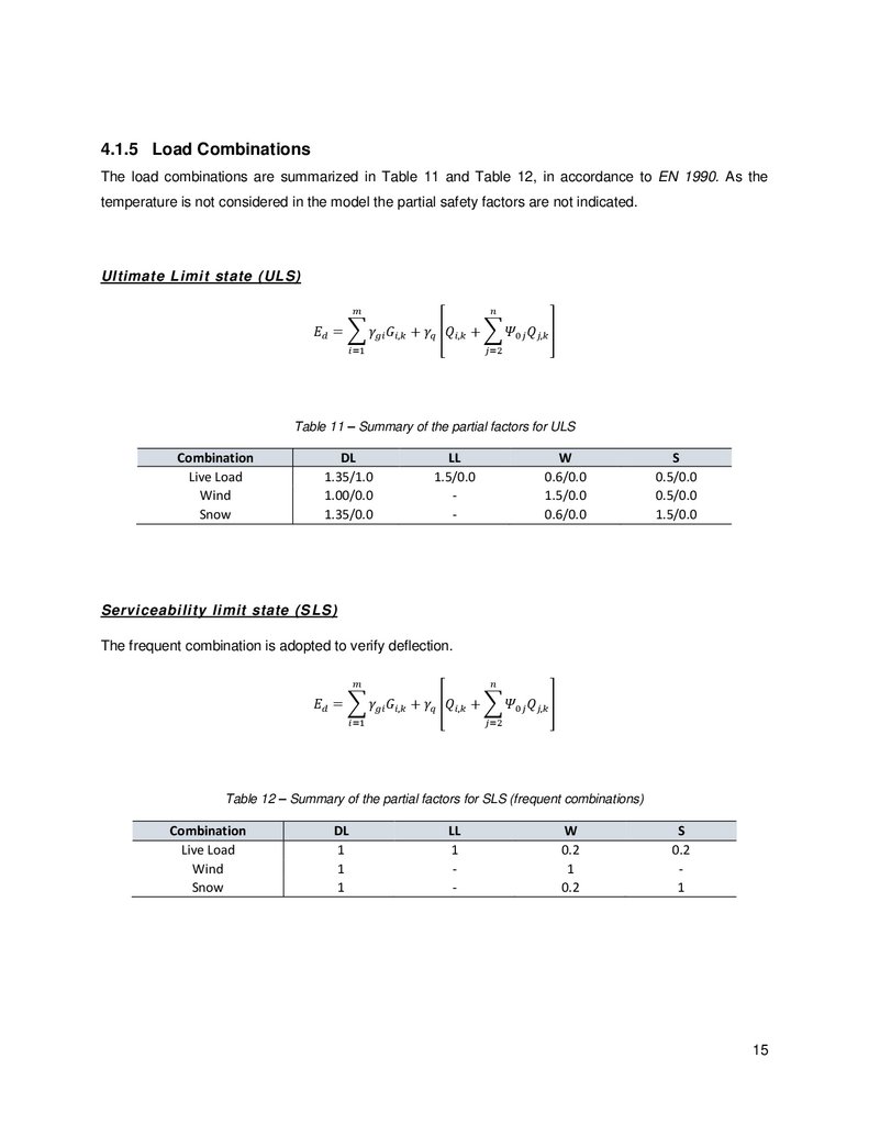
4.1.5 Load CombinationsThe load combinations are summarized in Table 11 and Table 12, in accordance to EN 1990. As the
temperature is not considered in the model the partial safety factors are not indicated.
Ultimate Limit state (ULS)