


 Construction
Similar presentations:
")


Original Research
1.
Original ResearchFlexural behaviour of a new lightweight
glass fibre-reinforced polymer–metal
string bridge with a box-truss
composite girder
Advances in Structural Engineering
2020, Vol. 23(1) 104–117
Ó The Author(s) 2019
Article reuse guidelines:
sagepub.com/journals-permissions
DOI: 10.1177/1369433219866088
journals.sagepub.com/home/ase
Haifeng Mao1, Dongdong Zhang2 , Li Chen3, Qilin Zhao1,
Xiaoping Su1 and Jiaxin Yuan2
Abstract
A new glass fibre-reinforced polymer–metal structure with a string box-truss girder was designed as a vehicular emergency bridge.
The glass fibre-reinforced polymer–metal emergency bridge is intended to be lightweight, structurally sound, with a long span and
modular feasibility, and associated with a faster construction bridging system. In this study, the detailed conceptual design of the new
bridge is described first. A large-scale static bending loading test was carried out on a fabricated bridge to examine its actual flexural
performance under the serviceability limit state. The experimental emergency bridge exhibited a satisfactory overall stiffness and
loading-carrying capacity in terms of its intended applications. Its linear-elastic flexural behaviour implies that the structural design of
such a unique emergency bridge subjected to positive flexural moment is stiffness-driven instead of strength-driven. Furthermore,
structural computational models, including three-dimensional finite element models and a simplified analytical planar model, were constructed and validated by comparing with the experimental results. The elicited comparisons indicated that the realistic nodal stiffness
of the hybrid pre-tightened teeth connection and its adjacent steel planar gusset plates ought to be considered in numerical and analytical modelling. Correspondingly, during the preliminary design phase and calculations, the flexural behaviour of this unique emergency
bridge can be predicted using the validated numerical and simplified analytical models.
Keywords
bridge engineering, fibre-reinforced polymer, finite element analysis, flexural performance, hybrid structure, non-destructive static test,
string structure, truss
Introduction
Pultruded fibre-reinforced polymer (FRP) materials
are extensively used in civil engineering structures
given their excellent characteristics, such as low selfweight, increased strength and good corrosion resistance (Correia et al., 2015; Gand et al., 2013; Zhao and
Zhang, 2007). Specifically, unidirectional pultruded
FRP profiles feature an excellent material strength in
the axis direction (Teng et al., 2016; Wang et al., 2018;
Yang et al., 2015; Zhao and Zhang, 2007). However,
compared to conventional steel materials, pultruded
FRP profiles have lower elastic moduli and shear
strengths, thereby prohibiting full utilisation of the
materials’ potential (Wu and Bai, 2014; Yang et al.,
2015). It seems that if these pultruded FRP profiles are
incorporated into the preferred truss structures in
which each element mainly bears axial loading rather
than shear loading, these disadvantages can be
overcome at the structural level. The inherent lack of
material stiffness can be compensated by the enhancement in stiffness at the structural level of the truss system (Yang et al., 2015). The increased strength of FRP
materials is fully utilised in these composite truss structures, thereby achieving further weight reduction.
1
College of Mechanical and Power Engineering, Nanjing Tech University,
Nanjing, China
2
College of Field Engineering, Army Engineering University of PLA,
Nanjing, China
3
Nanjing Institute of Technology, Nanjing, China
Corresponding authors:
Dongdong Zhang, College of Field Engineering, Army Engineering
University of PLA, Nanjing 210007, Jiangsu, China.
Email: zhangdodo1986@sohu.com
Qilin Zhao, College of Mechanical and Power Engineering, Nanjing Tech
University, Nanjing 211800, Jiangsu, China.
Email: zhaoqlin2015NUT@163.com
2.
Mao et al.In recent years, a range of planar trusses made of
pultruded glass fibre-reinforced polymer (GFRP) profiles has been used in pedestrian bridges (Feng et al.,
2013; Keller et al., 2007; Lee and Sam, 2010). In addition, some FRP space truss made of pultruded GFRP
profiles are also developed (Kostopoulos et al., 2005;
Yang et al., 2015). It was noted that for these trusses,
the used pultruded GFRP profiles were mainly jointed
by adhesive or mechanical bolted connections.
Regarding bridges intended for emergency purposes,
the FRP trusses could satisfy their primary requirements: lightweight for transport facilities and faster
construction (Russell and Thrall, 2013). A 20 m
GFRP planar truss was designed as an emergency
vehicular bridge, and the pultruded GFRP elements
were connected by bolting them with bonded steel
reinforcement (Sedlacek et al., 2004). A 30-m GFRP
pre-stressed trussed girder was designed as a dismountable vehicular bridge, and the GFRP tubes were
jointed using steel bearing-type connections (Teixeira
et al., 2014). An 8-m GFRP planar truss was designed
as an emergency bridge, and the pultruded FRP tubes
were held together by bolting connectors (Iwao and
Itaru, 2010). Compared to the existing emergency
bridges with FRP slab and box beams (Alampalli,
2006; Ji et al., 2010; Robinson and Kosmatka, 2008;
Zhou et al., 2014), these FRP trusses show apparent
lightweight characteristics.
Recently, a novel hybrid FRP–aluminium space truss
structure was designed as a modular emergency traffic
bridge with a span length of 12 m (Zhang et al., 2014).
The design load can withstand a four-wheel truck weighing 150 kN, but weighs approximately 12 kN. The emergency bridge is composed of two separated triangular
deck-truss girders linked by hinged transverse braces.
Each of the triangular girders consists of four, 3-m modules, jointed by male jugs and female jaws. Each triangular unit was made of an aluminium orthotropic deck
supported by pultruded FRP tubular elements. The FRP
tubes were connected with aluminium pieces based on an
advanced pre-tightened teeth connection (PTTC) technique for composites. The feasibility of the PTTC and the
good mechanical performances of the 12-m bridge specimen had been examined in previous studies (Zhang et al.,
2014, 2016a, 2016b, 2017, 2018, 2019). However, the span
length and the load-carrying capability of the 12-m simply
supported truss bridge were relatively low, which limited
the applicability and development of this type of lightweight bridging system. In the case of isolated mountainous terrains with large obstacles, a new emergency
bridge with longer span and larger load-carrying capability is desired.
The string structure is an advanced structural
form that can raise span length and load-carrying
capability of civil engineering structures (Aparicio and
105
Ruiz-Teran, 2007; Ruiz-Teran et al., 2009). With the
aid of lower string component, the upper main beam of
the overall structure is effectively supported by the
brace struts. An upwards force is generated by the
lower string component and is then transferred from
the brace struts to the upper main beam, effectively
enhancing the overall bending stiffness of the structural
system. In this case, a large span could be achieved.
For example, the string structures with trussed main
beam have been designed for large-span roof structures
(Chen and Dong, 2002; Qin et al., 2007) and vehicular
bridges (Roik, 2011; Ruiz-Teran and Aparicio, 2008).
It seems that if the said string structure is applied to
the aforementioned 12-m hybrid FRP–aluminium
space truss bridge, an enhanced span length and loadcarrying capability can be effectively achieved.
In this study, based on the optimisation and redesign of the original 12-m version, a new lightweight
string structure with a box-truss composite girder was
designed and manufactured for an emergency bridge
with a span length of 51 m and a vehicular load capacity of 200 kN. Considering the structural form of the
new 51-m string bridge differs considerably from that
of the 12-m original model, it is thus necessary to study
further the mechanical performance of the new string
structure. A non-destructive bending loading test was
carried out to identify the characteristic flexural performances of the new bridge, in accordance to the serviceability limit state. To obtain a calculation model
that can accurately predict the deformation and internal force state, numerical analyses were performed and
compared with the experiments, based on two finite
element (FE) models that considered the realistic nodal
stiffness of the PTTC and its adjacent planar gusset
plates. In addition, the spatial structure was simplified
as a planar analytical model and solved to allow its
comparison with experimental work. The research
results presented in this work are expected to contribute a valuable approach that can lead to the further
development of this new hybrid structural system.
Description of the bridge superstructure
The lightweight, long-span emergency bridge that uses
a string composite box-truss girder was specifically
proposed for disaster relief in isolated mountainous
terrains where critical situations occur and numerous
restrictions are imposed. Availability of such a lightweight bridge becomes all the more important when
existing prefabricated steel emergency bridges (Foss
and Gander, 2001; Hu, 2008; Russell and Thrall,
2013), with their associated heavy machinery and carrying vehicles, might be unable to access the site. In
this work, the design criteria for the construction of
emergency bridges (General Code for Military Bridge
3.
106Advances in Structural Engineering 23(1)
End unit
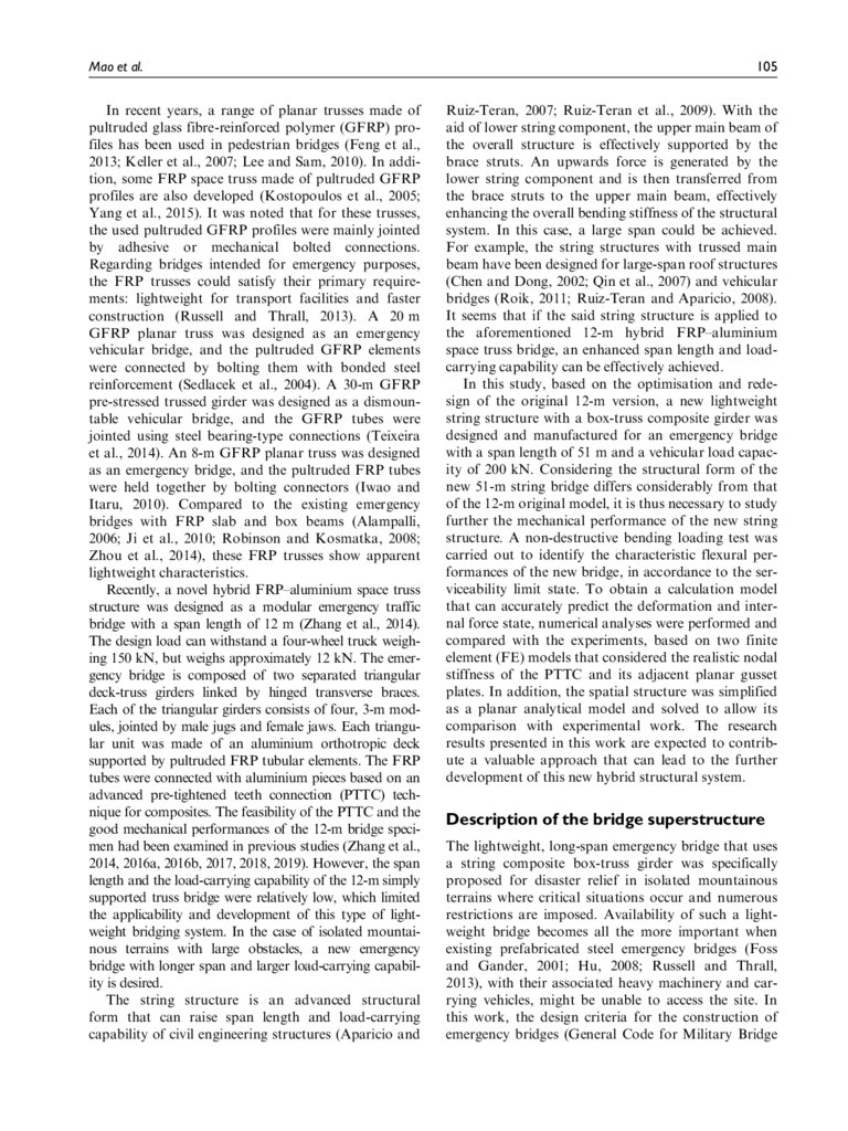
Figure 1. Bridge design concept.
Design, GJB 1162-91, 1992) were used for the bridge.
The design requirements of the emergency bridge
require that it possesses a capacity to carry a four-wheel
truck weighing 200 kN (LT-20). An impact coefficient m
of approximately 0.15 was considered, as specified in the
code (General Code for Design Load of Military
Bridges, GJB 435-88, 1988). As specified in the code, the
bridge was designed based on Allowable Stress Design.
The emergency bridge was designed as a single-span,
simply supported bridge, which corresponded to onelane and twin-trackway traffic live loads.
Figure 1 shows the overall concept of the emergency
bridge. The bridge has a total length of 54 m, a span
length of 51 m and a width of 3.2 m. The support
length at the two ends of the simply supported bridge
is 1.5 m. The overall bridge is consisted of an upper
main girder and a lower string component. The upper
main girder has a GFRP–metal box-truss structural
form that consisted of seven modular standard units
and two end units, which are longitudinally jointed by
steel male jugs and female jaws. The lower string component is composed of two parallel GFRP string pull
bars and corresponding steel brace struts. Each of the
GFRP string pull bars consist of several segments
jointed by steel male jugs and female jaws based on
PTTC. The brace struts are also jointed with the upper
main girder and the string pull bar by pin joints.
Upper main box-truss girder
In the upper main girder of the bridge, the standard
unit has a length of 6.0 m, a width of 3.2 m and a
depth of 1.2 m. Each of the standard units consisted of
twin separated triangular deck-truss girders fixed by a
series of upper steel I-type beam transverse braces and
GFRP lower planar-truss transverse braces. The clearance distances between the twin triangular girders are
0.8 and 2.0 m for the upper and lower surfaces, respectively. Each of the triangular girders was composed of
an aluminium orthotropic deck supported by GFRP
lower chords, web diagonals and vertical elements. The
aluminium orthotropic deck was consisted of a thin
slab with a thickness of 4.0 mm and a series of crisscrossing I-type beams, jointed by welding technology.
The GFRP tubular elements were connected using the
conventional weld connection of steel pieces, based on
the PTTC (Zhang et al., 2014). The upper steel transverse braces with I-type profiles are fixed with the two
triangular girders by rigid joints using welding and
bolted connections. The lower planar-truss transverse
braces were consisted of some lateral and diagonal
members, which were connected to the lower chords of
the two triangular girders using steel pin joints.
It is noted that the structural form of this new string
bridge differs considerably from the original version.
In the original version, the aforementioned diagonal
4.
Mao et al.members for the lower transverse braces did not exist.
Herein, the application of the lower planar-truss transverse braces was mainly to enhance the torsional resistance of the upper main box-truss girder and the entire
string structural system. Meanwhile, the separated twin
triangular units were integrally fixed as an entire body
using upper rigid transverse braces and lower hinged
planar-truss transverse braces. Moreover, to enlarge
the overall structural bending stiffness, the depth of
the triangular girders increased from the original value
of 0.85 to 1.2 m. To raise the modular feasibility and
reduce the erection time, the length of the standard
unit increased from the original value of 3.0 to 6.0 m.
The overall structural form of the end units is
almost the same with that of the standard units.
However, it is noted that to facilitate the use of the
emergency bridge by vehicles through the two end
units, a 20% slope was set. Moreover, a support length
of 1.5 m was selected for the end units. In the support
region, aluminium with a length of 1.5 m was added in
contact with the grounding member to improve the
structural stability and the torsional rigidity of the
overall bridge under eccentric vehicular loads. For this
end unit, most of its elements and used materials are
the same as those of the standard units. However, steel
profiles were finally selected, instead of the GFRP profiles, as the materials for the verticals and web diagonals near the side segment. The aluminium profiles
were used for the lower chords of the end units. This is
mainly because the end units placed on the ground
were subjected to a complicated loading condition and
because those trussed elements always bear complicated stress states that are harmful to the GFRP profiles. Thus, an aluminium and steel were finally used
for all the lower chords and some trussed elements
near the side support region.
Lower string component
The lower string component is mainly composed of
two parallel string pull bars and brace struts. The
string pull bars consisted of several GFRP tubes
jointed using steel male jugs and female jaws based on
PTTC. The string pull bars were anchored at 4.35 m
away from the end side of the lower chord of the upper
main girder. An adjusting nut was then installed near
the anchorage point to adjust pre-tension of the string
pull bars. The brace strut was located at 18.0 m away
from the end side of the lower chord of the upper main
girder (i.e. at one-third of the total length of the
bridge). The brace strut consisted of two vertical struts,
a diagonal strut and a cross strut. The role of the brace
struts that supported the upper main girder was mainly
manifested by the two vertical steel strut members. The
diagonal and cross struts mainly enhanced the stability
107
of the brace struts. The vertical members of the brace
struts were connected directly to the steel male jugs and
female jaws of lower chords and to the string pull bars
using pin joints. The GFRP cross and diagonal struts
were also hinged to the vertical steel struts by pins.
Material mechanical properties
For these pultruded GFRP elements, two types of
circular-tube cross-sections were selected. One round
of tubing with an outer diameter of 104 mm and a wall
thickness of 8 mm was applied to the lower chords,
the web diagonals and the string pull bars. Another
round of tubing with an outer diameter of 60 mm and
a wall thickness of 6 mm was used for the verticals of
the triangular girder, the lateral and diagonal elements
of the planar-truss transverse braces, and the diagonal
and cross struts of the brace struts of the string component. These pultruded FRP profiles were made of
roving and mat of E-glass fibres at an approximate
volume ratio of 80%. The fibre fractions were approximately 89.2% per weight, of which approximately
80% was longitudinal continuous glass fibre and 9.2%
was glass fibre roving and mat. Vinyl ester resin was
selected as the matrix. The standard GFRP tubes were
pultruded at Nanjing Jinglue FRP Co., Ltd., China.
The elastic modulus in the pultrusion direction of
GFRP elements were quoted by the manufacturer to
be equal to approximately 59.2 GPa.
For the other metal profiles, wrought aluminium
7005 was selected for the crisscrossing I-type beams
and thin slab. The upper transverse braces between the
two triangular deck-truss girders, the verticals and web
diagonals near the side segment of the end units were
made of I-type profiles with DB685 steel. The vertical
struts of the string component were made of Q390 steel.
Q390 steel and 7005 aluminium were used for the external and internal tubes, respectively. These steel planar
gusset plates of the nodal joints that were attached to
the external steel tubes of PTTC had a thickness of
2.0 mm and were made of Q390. The mechanical properties of the used composite and metal materials were
provided by the manufacturer, as listed in Table 1.
The total weight of the emergency bridge is approximately 162 kN. With a desired low self-weight, the
designed bridge can satisfy the primary lightweight
requirements for transport facilities, modular feasibility and faster construction in isolated mountainous terrains. The bridge is to be erected in a bestraddled
erection procedure with the aid of a launching nose, as
is the case in most deployable bridges (Foss and
Gander, 2001; Hu, 2008). The erection time of the 51m FRP–metal emergency bridge measured to be
approximately 160 min. Compared to the existing
assembly steel truss bridges with similar structural
5.
108Advances in Structural Engineering 23(1)
Table 1. Mechanical properties of used materials.
Materials
Strength (MPa)
Modulus of elasticity (GPa)
Poisson’s ratio
GFRP
Aluminium alloy
Q390 Steel
DB685 Steel
Compressive = 560, tensile = 1320
Compressive = 280, tensile = 345
Compressive = 390, tensile = 490
Compressive = 590, tensile = 685
E1 = 59.2
E = 70
E = 206
E = 206
v12 = 0.23
v = 0.32
v = 0.30
v = 0.30
GFRP: glass fibre-reinforced polymer.
Figure 2. Static loading test of the large-scale prototype bridge.
systems and erection methods (Foss and Gander,
2001; Hu, 2008; Russell and Thrall, 2013), the modular
FRP–metal emergency bridge has a higher cost but
shows a lower self-weight and a faster erection process.
For example, the erection time of the assembly Heavy
Truss Bridge (HTB) with a steel string truss girder,
which is served in China disaster relief operations and
has a span length of 50.7 m and a total weight of
402.5 kN (Hu, 2008), take approximately 240 min.
The well-known UK Medium Girder Bridge (MGB)
with a similar string truss girder, which has a span
length of 51 m and a total weight of 403 kN, takes
approximately 200 min in the erection process (Foss
and Gander, 2001; Russell and Thrall, 2013). As
already stated, the proposed FRP–metal emergency
bridge offers improvements over the above HTB and
MGB systems in terms of weight and erection time.
Experimental investigation
Specimen and test set-up
A full-scale bridge was fabricated in the workshop of
Harzone Industry Co., Ltd., China, and then erected
onsite as an experimental structure with the aid of a
light-duty crane. A static bending loading test was carried out under design load on the large-scale, simply
supported bridge. The main purpose of the tests was
to examine the actual flexural behaviour of this new
bridge in accordance to the serviceability limit state.
The fabricated bridge and its detailed test setup are
presented in Figure 2.
The boundary constraints were simplified to emulate the simply supported conditions. Two large-scale
prefabricated steel frames, with sufficient stiffness and
strength, were placed in the stack at both ends of the
6.
Mao et al.109
Figure 3. Instrumentation for the displacement and strain measurements.
bridge and selected as the end supports for convenience. The bridge was directly placed on the top surface
of the end supports that had a support length of
approximately 1.5 m. These end supports were placed
on the levelled surface of a heavy concrete floor and at
a suitable height of approximately 3.2 m so that the
bridge could facilitate a sufficient vertical deformation.
During the setup of the end supports, the bridge was
transversely and longitudinally adjusted into a horizontal state using a level metre set on the top surface
of the bridge deck.
To emulate the bending loading condition, four
ready-made, short wood sleepers were placed symmetrically at the mid-span of the bridge to support the
applied steel block loading. Each of these wood sleepers was selected to be a cuboid with a length of 0.6 m,
width of 0.1 m and height of 0.1 m. The distance
between the centres of the two wood sleepers in the
span direction was 3.0 m; while that in the width direction was 2.0 m, which in effect equalled the clear distance between the two lower chords. The distance from
the outer edge of the bridge deck to the centre of each
wood sleeper was 0.6 m.
The design load of the bridge was 200 kN. When an
impact factor of 1.15 was considered, the maximum
applied loads in this experiments were finally set to
230 kN. In the loading process, four loading steps
were scheduled, namely, at 110, 160, 210 and 230 kN.
Each loading level was achieved using steel blocks with
specified self-weights. Three types of ready-made steel
blocks were used with weights of 20, 30 and 50 kN.
The steel block increased progressively according to
the corresponding loading step during the test. The
loading and uploading processes of the steel blocks
were carried out with the aid of a portal crane.
Measurement instrumentation
During the loading process, the overall displacement
of the structure and the longitudinal strains at some
concerned trussed members were simultaneously measured. The corresponding instrumentation layout is
shown in Figure 3. The vertical displacements were
mainly measured along the lower chords. Seven points
were instrumented (D1–D7). The vertical displacement
was measured by an electronic total station. The longitudinal strains were mainly measured at the main longitudinal I-type beam of the orthotropic deck, the left
and right GFRP lower chords, and the left and right
GFRP string pull bars at the mid-span of the bridge,
where the overall bending moment resisted by these
longitudinal profiles was maximised for this simply
supported bridge under applied loads. The longitudinal strain was measured by calibrated unidirectional
strain gauges. For the main longitudinal beams, three
strain gauges were located at the upper flange, lower
flange and middle position at every instrumented Itype cross-section. For the GFRP tubular elements,
three strain gauges were laid equidistantly around the
tubular cross-section. The strain data were synchronously recorded by a static strain indicator data acquisition system connected to a computer.
7.
110Advances in Structural Engineering 23(1)
(a)
(b)
Figure 4. Measured deformation: (a) overall vertical deformation and (b) vertical displacement at mid-span.
Experimental results
Load–displacement responses. The recoded vertical deformation of the bridge is shown in Figure 4(a), where
the positive vertical axis represents the downwards displacement. The results showed that the lower chord
deformed with a consistent increase in its shape under
various loading steps, and the deformed shape was
symmetrical about the span centre, as expected. The
maximum displacement directly measured at the midspan was approximately 423.8 mm. The displacements
measured by dial gauges D1 and D7 gradually
increased to the maximum values of 13.08 and
17.35 mm, respectively. In contrast, under an ideal
simply supported condition, the displacement at the
two ends would be 0 mm. Thus, after subtracting the
average vertical deformation at the two end supports,
the actual maximum deflection at the mid-span was
found to be 408.6 mm. According to the design code
(General Code for Military Bridge Design, GJB 116291, 1992), the allowed deflection for such a simply supported emergency bridge was below L/120 (i.e.
425 mm), where L is the span length. Therefore, the
experimental deformation of the bridge meets the
requirements of the allowed deflection limit.
Furthermore, the measured vertical displacement at
the mid-span of the bridge is shown in Figure 4(b).
The figure shows that the measured vertical displacement curve varied almost linearly with no residual displacement after loading, which proves that the
mechanical response of the bridge was near the linearelastic range under the serviceability limit state, as
expected. By linearly fitting the measured data, the
slope of the load–displacement curve was found to be
approximately equal to 5.66 3 105 N/m, which
reflects the integral structural stiffness of the fabricated
bridge. If the length dimension of the bridge is
excluded from the aforementioned integral structural
stiffness, the overall bending stiffness (EI) was estimated at 1.56 3 109 N m2.
Load–strain responses. The longitudinal strains in the
measured GFRP lower chords are shown in Figure
5(a). Similarly, all the nearly linear strain responses
shows the response of the bridge was in the elastic
range, as expected. For the same tubular cross-sections, the longitudinal strains at the three measured
points exhibited minor discrepancies with respect to
each other. For example, at 230 kN, the maximum differences between measured strains and average values
were approximately equal to 0.2%, 9.8% and 9.6%,
for L1-1, L1-2 and L1-3, respectively, while those for
L2-1, L2-2 and L2-3 were approximately equal to
0.1%, 5.9% and 6.0%, respectively. These results indicated that the GFRP lower chords were mainly subjected to an axial stress state, which agreed well with
the axial mechanical characteristics of the unidirectional pultruded GFRP composites with low interlaminar shear strength. Thus, the pultruded GFRP
tubes were appropriate for use as the lower chords. In
addition, the measured lower chords imposed a tensile
state, an effect that was mainly caused by the positive
bending moment of the upper main girder subjected to
downwards vertical loads. It is concluded that the positive bending moment in the upper main girder was
mainly resisted by an axial tension loading of the
GFRP lower chord, combined with an axial compressive loading of the longitudinal beams of the orthotropic deck (as described in the following paragraph).
The longitudinal strains in the measured GFRP pull
bars of the string component are shown in Figure 5(b).
For each tubular cross-section, the discrepancies of the
longitudinal strains at the different measured points
are also minor. At 230 kN, the differences between the
measured strain and average value are 0.2%, 1.4% and
8.
Mao et al.111
(a)
(b)
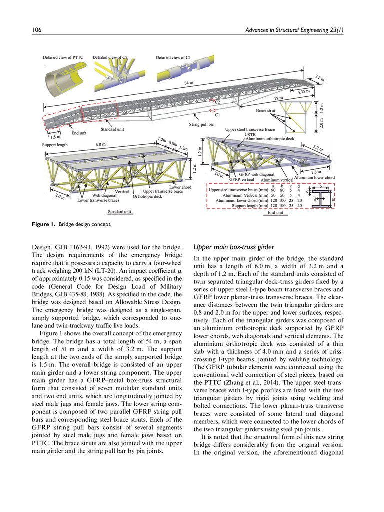
Figure 5. Measured strains at (a) GFRP trussed lower chord and (b) GFRP string pull bars.
1.3%, for the three measured points P1-1, P1-2 and
P1-3, respectively. The differences between the measured strains and average values were 4.6%, 6.5% and
2.0%, for the three measured points P2-1, P2-2 and
P2-3, respectively. This indicated that the GFRP pull
bars were also mainly subjected to an axial stress state,
as desired. Similarly, the application of the pultruded
GFRP members on the string component could maximise the mechanical advantages of composite materials. The string pull bars was in an axial tensile state. In
this case, the lower string component produced an
opposite force to the upper main girder in the effort to
resist the overall bending moment and for increasing
the overall bending stiffness of the hybrid system. It is
noted that the curves between the two parallel string
pull bars (or the two parallel lower chords) nearly coincided with each other, which was almost with the symmetric nature of the bridge under the on-axis loads
without torsion. The minor discrepancy of the two
curves was primarily caused by the minor eccentricity
during the actual loading process.
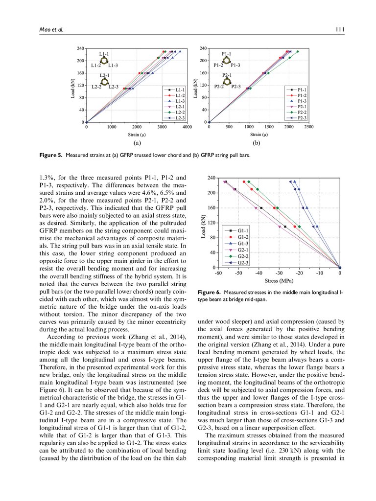
According to previous work (Zhang et al., 2014),
the middle main longitudinal I-type beam of the orthotropic deck was subjected to a maximum stress state
among all the longitudinal and cross I-type beams.
Therefore, in the presented experimental work for this
new bridge, only the longitudinal stress on the middle
main longitudinal I-type beam was instrumented (see
Figure 6). It can be observed that because of the symmetrical characteristic of the bridge, the stresses in G11 and G2-1 are nearly equal, which also holds true for
G1-2 and G2-2. The stresses of the middle main longitudinal I-type beam are in a compressive state. The
longitudinal stress of G1-1 is larger than that of G1-2,
while that of G1-2 is larger than that of G1-3. This
regularity can also be applied to G1-2. The stress states
can be attributed to the combination of local bending
(caused by the distribution of the load on the thin slab
Figure 6. Measured stresses in the middle main longitudinal Itype beam at bridge mid-span.
under wood sleeper) and axial compression (caused by
the axial forces generated by the positive bending
moment), and were similar to those states developed in
the original version (Zhang et al., 2014). Under a pure
local bending moment generated by wheel loads, the
upper flange of the I-type beam always bears a compressive stress state, whereas the lower flange bears a
tension stress state. However, under the positive bending moment, the longitudinal beams of the orthotropic
deck will be subjected to axial compression forces, and
thus the upper and lower flanges of the I-type crosssection bears a compression stress state. Therefore, the
longitudinal stress in cross-sections G1-1 and G2-1
was much larger than those of cross-sections G1-3 and
G2-3, based on a linear superposition effect.
The maximum stresses obtained from the measured
longitudinal strains in accordance to the serviceability
limit state loading level (i.e. 230 kN) along with the
corresponding material limit strength is presented in
9.
112Advances in Structural Engineering 23(1)
Table 2. Comparison of the measured longitudinal stress with the corresponding material strength.
Member profiles
GFRP lower chords
GFRP string pull bars
Aluminium I-type beams
Measured results (MPa)
Material strength (MPa)a
176.3
440
108.3
440
–56.9
–280
GFRP: glass fibre-reinforced polymer.
a
A safety factor of 3.0 was used for the material strength of GFRP tubes.
Figure 7. Two finite element models with different nodal stiffness.
Table 2. The comparison shows that the measured
longitudinal stresses in the structural elements were
much smaller than the corresponding material strength
for all the instrumented members. Specifically, the
longitudinal mechanical properties of the pultruded
GFRP profiles and metal materials were not fully
exerted. However, the measured maximum vertical
deformation approached the allowed deflection limit.
It is worth pointing out that this behaviour implies
that the design of the hybrid GFRP–metal bridge
superstructure undergoing positive flexural moments is
stiffness-driven instead of strength-driven.
Numerical and analytical analyses
FE modelling
Two different FE models, with different modelling
details of the PTTC (with a unique hybrid configuration) and its additional planar gusset plates, were constructed using ANSYS, as shown in Figure 7. Model-1
(M1) was first built, whereby the hybrid PTTC and its
additional planar gusset plates at the intersection joints
between the interlocked GFRP elements were
simplified and modelled as the same segment as that
used for the corresponding GFRP tubes. Specifically,
the realistic nodal stiffness of the PTTC and its additional planar gusset plates were not modelled in a realistic manner. It was concluded that this conventional
modelling method yielded sufficient accuracy in the
calculation of the composite bridges with bolting or
bonded connections (Bai and Yang, 2013; Feng et al.,
2013; Keller et al., 2007; Kostopoulos et al., 2005), and
in the original short-span version (Zhang et al., 2014).
However, for the presented new string bridge with a
long span, it is believed that the realistic nodal stiffness
would considerably influence the overall bending stiffness of the structure. Thereafter, Model-2 (M2) was
constructed that considered the realistic nodal stiffness
of the PTTC and its additional planar gusset plates.
M1. In the modelling process of the upper main girder,
Shell-63 elements were selected for the aluminium thin
slab. Beam-188 elements were applied to the crisscrossing aluminium I-type beams and to the upper steel
transverse braces. A mesh size of 100 mm was selected.
For modelling the GFRP trussed elements, including
10.
Mao et al.the lower chords, web diagonals, verticals and the
lower planar-truss transverse braces, Beam-188 elements were selected and a mesh size of 50 mm was
used. For modelling the lower string components,
including the GFRP string pull bars, and the steel vertical struts, the GFRP diagonal and cross struts of the
brace struts, the element Beam-188 with a mesh size of
50 mm were also employed.
In the modelling process of the interlocked GFRP
elements, all their nodal joints (the composite PTTCs
and the additional planar gusset plates) were simplified
to have the same characteristics as those of GFRP
tubes, that is, the nodal jointing elements had the same
cross-section and material properties as their attached
GFRP elements. The steel male jug and female jaws
were simplified and modelled as the same segment to
that used for the corresponding GFRP tubes. Actually,
by default, all the nodal joints among the trussed elements modelled by Beam-188 were rigid nodes.
However, the end connectors of some elements were
pin joints (i.e. the male jug and female jaws), such as
the tubular elements of the lower planar-truss transverse braces, the string pull bars and the brace struts of
the lower string component. Moreover, the connections between the two adjacent modules of the upper
main girder were also created by male jugs and female
jaws. In M1, the total number of elements was 28704
and 23758 for Shell-63 and Beam-188, respectively.
In M1, the generalised Hooke’s law of linear-elastic
isotropic materials was used as the constitutive material law of the metal profiles and the GFRP profiles.
The mechanical properties of the GFRP and metal
profiles used as inputs are listed in Table 1. The nonlinear behaviour of the materials was not considered
because the strain induced was within the linear strain
range. The buckling issue of the compressive members
was also not considered. The corresponding uniformly
distributed wheel load was transformed into point
loads within the loading area on the thin slab of the
bridge deck. The displacement boundary conditions
and loading conditions were set in accordance to the
experiments.
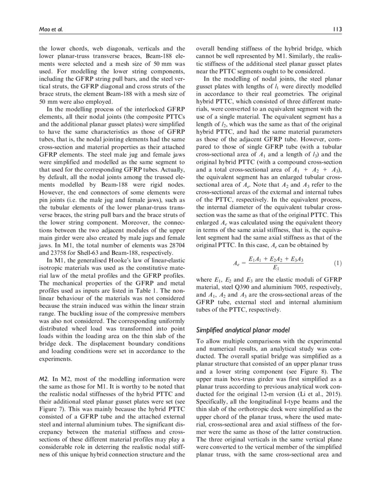
M2. In M2, most of the modelling information were
the same as those for M1. It is worthy to be noted that
the realistic nodal stiffnesses of the hybrid PTTC and
their additional steel planar gusset plates were set (see
Figure 7). This was mainly because the hybrid PTTC
consisted of a GFRP tube and the attached external
steel and internal aluminium tubes. The significant discrepancy between the material stiffness and crosssections of these different material profiles may play a
considerable role in deterring the realistic nodal stiffness of this unique hybrid connection structure and the
113
overall bending stiffness of the hybrid bridge, which
cannot be well represented by M1. Similarly, the realistic stiffness of the additional steel planar gusset plates
near the PTTC segments ought to be considered.
In the modelling of nodal joints, the steel planar
gusset plates with lengths of l1 were directly modelled
in accordance to their real geometries. The original
hybrid PTTC, which consisted of three different materials, were converted to an equivalent segment with the
use of a single material. The equivalent segment has a
length of l2, which was the same as that of the original
hybrid PTTC, and had the same material parameters
as those of the adjacent GFRP tube. However, compared to those of single GFRP tube (with a tubular
cross-sectional area of A1 and a length of l3) and the
original hybrid PTTC (with a compound cross-section
and a total cross-sectional area of A1 + A2 + A3),
the equivalent segment has an enlarged tubular crosssectional area of Ae. Note that A2 and A3 refer to the
cross-sectional areas of the external and internal tubes
of the PTTC, respectively. In the equivalent process,
the internal diameter of the equivalent tubular crosssection was the same as that of the original PTTC. This
enlarged Ae was calculated using the equivalent theory
in terms of the same axial stiffness, that is, the equivalent segment had the same axial stiffness as that of the
original PTTC. In this case, Ae can be obtained by
Ae =
E1 A 1 + E2 A 2 + E3 A3
E1
ð1Þ
where E1, E2 and E3 are the elastic moduli of GFRP
material, steel Q390 and aluminium 7005, respectively,
and A1, A2 and A3 are the cross-sectional areas of the
GFRP tube, external steel and internal aluminium
tubes of the PTTC, respectively.
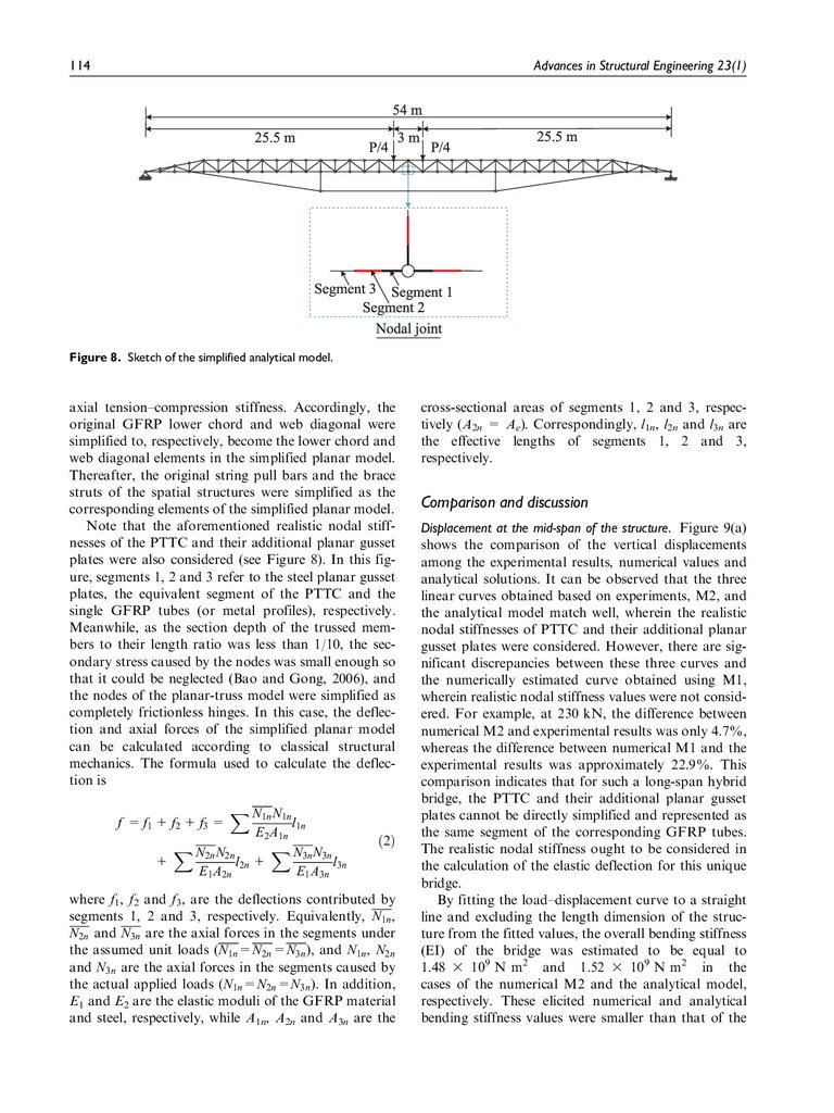
Simplified analytical planar model
To allow multiple comparisons with the experimental
and numerical results, an analytical study was conducted. The overall spatial bridge was simplified as a
planar structure that consisted of an upper planar truss
and a lower string component (see Figure 8). The
upper main box-truss girder was first simplified as a
planar truss according to previous analytical work conducted for the original 12-m version (Li et al., 2015).
Specifically, all the longitudinal I-type beams and the
thin slab of the orthotropic deck were simplified as the
upper chord of the planar truss, where the used material, cross-sectional area and axial stiffness of the former were the same as those of the latter construction.
The three original verticals in the same vertical plane
were converted to the vertical member of the simplified
planar truss, with the same cross-sectional area and
11.
114Advances in Structural Engineering 23(1)
Figure 8. Sketch of the simplified analytical model.
axial tension–compression stiffness. Accordingly, the
original GFRP lower chord and web diagonal were
simplified to, respectively, become the lower chord and
web diagonal elements in the simplified planar model.
Thereafter, the original string pull bars and the brace
struts of the spatial structures were simplified as the
corresponding elements of the simplified planar model.
Note that the aforementioned realistic nodal stiffnesses of the PTTC and their additional planar gusset
plates were also considered (see Figure 8). In this figure, segments 1, 2 and 3 refer to the steel planar gusset
plates, the equivalent segment of the PTTC and the
single GFRP tubes (or metal profiles), respectively.
Meanwhile, as the section depth of the trussed members to their length ratio was less than 1/10, the secondary stress caused by the nodes was small enough so
that it could be neglected (Bao and Gong, 2006), and
the nodes of the planar-truss model were simplified as
completely frictionless hinges. In this case, the deflection and axial forces of the simplified planar model
can be calculated according to classical structural
mechanics. The formula used to calculate the deflection is
f = f1 + f2 + f3 =
X N1n N1n
l1n
E2 A1n
X N2n N2n
X N3n N3n
+
l2n +
l3n
E1 A2n
E1 A3n
ð2Þ
where f1, f2 and f3, are the deflections contributed by
segments 1, 2 and 3, respectively. Equivalently, N1n ,
N2n and N3n are the axial forces in the segments under
the assumed unit loads (N1n =N2n =N3n ), and N1n , N2n
and N3n are the axial forces in the segments caused by
the actual applied loads (N1n =N2n =N3n ). In addition,
E1 and E2 are the elastic moduli of the GFRP material
and steel, respectively, while A1n, A2n and A3n are the
cross-sectional areas of segments 1, 2 and 3, respectively (A2n = Ae). Correspondingly, l1n, l2n and l3n are
the effective lengths of segments 1, 2 and 3,
respectively.
Comparison and discussion
Displacement at the mid-span of the structure. Figure 9(a)
shows the comparison of the vertical displacements
among the experimental results, numerical values and
analytical solutions. It can be observed that the three
linear curves obtained based on experiments, M2, and
the analytical model match well, wherein the realistic
nodal stiffnesses of PTTC and their additional planar
gusset plates were considered. However, there are significant discrepancies between these three curves and
the numerically estimated curve obtained using M1,
wherein realistic nodal stiffness values were not considered. For example, at 230 kN, the difference between
numerical M2 and experimental results was only 4.7%,
whereas the difference between numerical M1 and the
experimental results was approximately 22.9%. This
comparison indicates that for such a long-span hybrid
bridge, the PTTC and their additional planar gusset
plates cannot be directly simplified and represented as
the same segment of the corresponding GFRP tubes.
The realistic nodal stiffness ought to be considered in
the calculation of the elastic deflection for this unique
bridge.
By fitting the load–displacement curve to a straight
line and excluding the length dimension of the structure from the fitted values, the overall bending stiffness
(EI) of the bridge was estimated to be equal to
1.48 3 109 N m2 and 1.52 3 109 N m2 in the
cases of the numerical M2 and the analytical model,
respectively. These elicited numerical and analytical
bending stiffness values were smaller than that of the
12.
Mao et al.115
(a)
(b)
Figure 9. Comparison of the experimental, numerical and analytical results: (a) vertical displacements at mid-span and (b) axial
forces on GFRP lower chords and string pull bars.
experimental structure that equalled 1.56 3 109 N m2.
This indicated that the numerical M2 and the analytical planar model over-predicted the actual vertical
deformation. The difference of the overall bending
stiffness was approximately 4.1% and 1.4% between
the numerical M2, analytical model and the experimental structure, respectively. It appears that in addition to experimental errors, this difference was mainly
attributed to some other complex local structural
details of the real structure that were not well simulated or modelled by the numerical and analytical
models, such as the detailed male jugs and female jaws,
the additional gusset plates of the bridge deck and so
on. In general, the minor discrepancy indicates that
the established numerical M2 and the simplified analytical planar model can be used to accurately predict
the overall deflection of the unique long-span hybrid
bridge.
Axial forces in measured trussed elements. In addition, the
axial forces among experimental results, numerical values and analytical solutions are compared in Figure
9(b). Similarly, the two linear curves obtained by the
experiments and numerical M2 coincide well with each
other. Meanwhile, the linear curve obtained from
numerical M1 also yielded a minor discrepancy compared to the experiments. At 230 kN, the maximum
differences between M1 and the experiments were
approximately 9.7% and 11.4% for the GFRP lower
chords and string pull bars, respectively, while the corresponding maximum differences between the elicited
results of M2 and the experiments were approximately
0.9% and 1.3%, respectively. It is noted that these outcomes are much different from those elicited in the
aforementioned regularity obtained from vertical displacements (see Figure 9(a)) where the linear curve of
M1 yielded a significant discrepancy compared to the
experiments. This indicated that the role of the realistic
nodal stiffness of the PTTC and their additional planar
gusset plates in terms of their effect in the generation
of axial forces was small. In the preliminary design
phase and calculations, the two FE models had a
higher accuracy for predicting the actual axial forces in
the GFRP lower chords and string pull bars. In addition, the maximum differences between the analytical
solutions and experimental results were approximately
3.4% and 2.0% for the GFRP lower chords and string
pull bars, respectively. Thus, the simplified planar
model can be used for accurate predictions of the axial
forces in the GFRP lower chords and string pull bars
of the unique spatial structural system.
Summary and conclusion
For provision of disaster relief in isolated mountainous
terrains when critical situations occur and in cases
where many restrictions are imposed, a new hybrid
GFRP–metal string structure was proposed to provide
a modular emergency bridge with a span length of
51 m and a vehicular load capacity of 200 kN. The
large-scale bridge consisted of an upper composite
box-truss girder and a lower hybrid string component.
The advanced hybrid PTTC technology was employed
for jointing the tubular GFRP elements. The new longspan bridge, which was redesigned based on the optimisation of an original, short-span, hybrid space truss
bridge model, features lightweight and structurally
sound. The total weight of the bridge was approximately 162 kN. With a low self-weight, the designed
bridge could satisfy the primary lightweight requirements for emergency purposes.
A bridge prototype was fabricated and then subjected to a large-scale, static bending loading test to
13.
116examine the actual flexural performances in accordance to the serviceability limit state. The experimental bridge showed satisfactory overall bending
stiffness and loading-carrying capacity in terms of
emergency vehicular bridge applications, while its
mechanical response displayed good linear-elastic
behaviour. The GFRP elements mainly withstood
axial forces, which agreed well with the axial mechanical characteristics of the unidirectional pultruded
GFRP composites. They were thus appropriate for
application to this hybrid string structure. The
experimental study showed the feasibility and effectiveness of the string component system in raising the
bridging span length and the load-carrying capacity
of the upper main box-truss girder. In addition, the
results indicate that the flexural design of such a
unique hybrid emergency bridge was stiffness-driven
instead of strength-driven.
To allow comparisons with experimental studies,
numerical analyses were conducted based on two 3dimensional FE models with different nodal stiffnesses.
The comparisons indicated that the realistic nodal stiffness of the hybrid PTTC and their adjacent planar gusset plates ought to be considered in the model. The
conventional modelling method used for the composite
bridge with bolting or bonded connections or shortspan versions, where the intersection joints between the
interlocked GFRP elements were just simplified as the
same segment of the adjacent GFRP tubes, was no longer applied to the presented hybrid long-span bridge.
Moreover, a simplified analytical planar model that
considered the realistic nodal stiffness was built and
validated based on the experimental results. In the initial design, the flexural behaviour of such a unique
bridge can be predicted using the validated numerical
and simplified analytical models with sufficient accuracy, including the overall deformation of the overall
structure and the axial force of GFRP lower chords
and string pull bars.
Declaration of conflicting interests
The author(s) declared no potential conflicts of interest with
respect to the research, authorship and/or publication of this
article.
Funding
The author(s) disclosed receipt of the following financial support for the research, authorship and/or publication of this
article: Financial supports from the National Natural
Science Foundation of China (51708552), the Natural
Science Foundations of Jiangsu Province (BK20170752),
the Postdoctoral Science Foundation Grant of China
Advances in Structural Engineering 23(1)
(2017M623401) and the Young Elite Scientist Sponsorship
are gratefully acknowledged.
ORCID iD
Dongdong Zhang
https://orcid.org/0000-0003-1343-5428
References
Alampalli S (2006) Field performance of an FRP slab bridge.
Composite Structures 72(4): 494–502.
Aparicio AC and Ruiz-Teran AM (2007) Two new types of
bridges: under-deck cable-stayed bridges and combined
cable-stayed bridges – the state of the art. Canadian Journal of Civil Engineering 34(8): 1003–1016.
Bai Y and Yang X (2013) Novel joint for assembly of allcomposite space truss structures: conceptual design and
preliminary study. Journal of Composites for Construction
17(1): 130–138.
Bao SH and Gong YQ (2006) Structural Mechanics. Wuhan,
China: Wuhan University of Technology Press.
Chen RY and Dong SL (2002) Design of exhibition hall steel
roof at Guangzhou international convention & exhibition
center. Spatial Structures 8(3): 29–34.
Correia JR, Bai Y and Keller T (2015) A review of the fire
behaviour of pultruded GFRP structural profiles for civil
engineering applications. Composite Structures 127:
267–287.
Feng P, Tian Y and Qin ZP (2013) Static and dynamic behavior of a truss bridge made of FRP pultruded profiles.
Industrial Construction 43(6): 36–41.
Foss CF and Gander TJ (2001) Jane’s Military Vehicles and
Logistics. London: Jane’s Information Group.
Gand AK, Chan TM and Mottram JT (2013) Civil and
structural engineering applications, recent trends, research
and developments on pultruded fiber reinforced polymer
closed sections: a review. Frontiers of Structural and Civil
Engineering 7(3): 227–244.
GJB 1162-91 (1992) General code for military bridge design.
Technical report, China National Military Standard, Beijing, China.
GJB 435-88 (1988) General code for design load for military
bridges. Technical report, China National Military Standard, Beijing, China.
Hu YP (2008) Structural Design and Erection Methods for
Military Bridges. Beijing, China: PLA Press.
Iwao S and Itaru N (2010) Load-bearing properties of an
FRP bridge after nine years of exposure. In: Proceedings
of the CICE 2010 – the 5th international conference on
FRP composites in civil engineering, Beijing, China, 27–29
September, pp. 474–477. Berlin: Springer.
Ji HS, Song WC and Ma ZGJ (2010) Design, test and field
application of a GFRP corrugated-core sandwich bridge.
Engineering Structures 32(9): 2814–2824.
Keller T, Bai Y and Vallée T (2007) Long-term performance
of a glass fiber-reinforced polymer truss bridge. Journal of
Composites for Construction 11(1): 99–108.
14.
Mao et al.Kostopoulos V, Markopoulos YP and Vlachos DE (2005)
Design and construction of a vehicular bridge made of
glass/polyester pultruded box girders. Plastics Rubber and
Composites 34(4): 201–207.
Lee C and Sam L (2010) Development of FRP bridges in the
UK – an overview. Advances in Structural Engineering 13:
5823–5835.
Li F, Zhang DD, Zhao QL, et al. (2015) A simple analytical
solution for predicting deflection of a hybrid FRP-aluminum modular space truss bridge. Journal of Central South
University 22(11): 4414–4425.
Qin J, Chen X and Xu R (2007) Design and experimental
study on the joints of nation gymnasium. Industrial Construction 37(1): 12–15.
Robinson MJ and Kosmatka JB (2008) Development of a
short-span fiber-reinforced composite bridge for emergency response and military applications. Journal of
Bridge Engineering 13(4): 388–397.
Roik K (2011) Composite road and railway bridges in Germany. In: Leon RT, et al. (eds) Composite Construction in
Steel and Concrete. New York: ASCE, pp. 286–301.
Ruiz-Teran AM and Aparicio AC (2008) Structural behaviour and design criteria of under-deck cable-stayed
bridges and combined cable-stayed bridges. Part 1: singlespan bridges. Canadian Journal of Civil Engineering 35(9):
938–950.
Ruiz-Teran AM and Aparicio AC (2009) Response of underdeck cable-stayed bridges to the accidental breakage of
stay cables. Engineering Structures 31(7): 1425–1434.
Russell BR and Thrall AP (2013) Portable and rapidly
deployable bridges: historical perspective and recent technology developments. Journal of Bridge Engineering 18:
1074–1085.
Sedlacek G, Trumpf H and Castrischer U (2004) Development of a light-weight emergency bridge. Structural Engineering International 14(4): 282–287.
Teixeira AMAJ, Pfeil MS and Battista RC (2014) Structural
evaluation of a GFRP truss girder for a deployable
bridge. Composite Structures 110(4): 29–38.
Teng JG, Zhang SS and Chen JF (2016) Strength model for
end cover separation failure in RC beams strengthened
with near-surface mounted (NSM) FRP strips. Engineering Structures 110: 222–232.
117
Wang X, Jiang L, Shen H, et al. (2018) Long-term performance of pultruded basalt fiber reinforced polymer profiles under acidic conditions. Journal of Materials in Civil
Engineering 30(6): 04018096.
Wu C and Bai Y (2014) Web crippling behaviour of pultruded glass fibre reinforced polymer sections. Composite
Structures 108(1): 789–800.
Yang X, Bai Y and Ding F (2015) Structural performance of
a large-scale space frame assembled using pultruded
GFRP composites. Composite Structures 133: 986–996.
Zhang DD, Huang YX, Zhao QL, et al. (2016a) Evaluation
of the torsional mechanism by analytical solution for a
hybrid fiber-reinforced polymer–aluminum triangular
deck truss beam. Advances in Structural Engineering 19(5):
871–879.
Zhang DD, Li F, Shao F, et al. (2019) Evaluation of equivalent bending stiffness by simplified theoretical solution for
an FRP–aluminum deck–truss structure. KSCE Journal of
Civil Engineering 23(1): 367–375.
Zhang DD, Li F, Zhao QL, et al. (2016b) Analytical solutions of the torsional mechanism for a new hybrid fiberreinforced polymer-aluminum twin-trackway space truss
bridge. Advances in Structural Engineering 19(12):
1832–1840.
Zhang DD, Zhao QL, Huang YX, et al. (2014) Flexural
properties of a lightweight hybrid FRP-aluminum modular space truss bridge system. Composite Structures 108(1):
600–615.
Zhang DD, Zhao QL, Li F, et al. (2017) Experimental and
numerical study of the torsional response of a modular
hybrid FRP-aluminum triangular deck-truss beam. Engineering Structures 133: 172–185.
Zhang DD, Zhao QL, Li F, et al. (2018) Torsional behavior
of a hybrid FRP-aluminum space truss bridge: experimental and numerical study. Engineering Structures 157:
132–143.
Zhao XL and Zhang L (2007) State-of-the-art review on
FRP strengthened steel structures. Engineering Structures
29(8): 1808–1823.
Zhou YZ, Fan HL, Jiang KB, et al. (2014) Experimental
flexural behaviors of CFRP strengthened aluminum
beams. Composite Structures 116(9): 761–771.