


 Construction
Similar presentations:


")


Designing long-span steel girders by applying displacement control concepts
1.
Designing long-span steel girders by applying displacement control conceptsN. Antonioua,* , Th. Nikolaidisb , C. Baniotopoulosa,b
a
School of Civil Engineering, University of Birmingham, Birmingham B15 2TT, United Kingdom
b
Department of Civil Engineering, Aristotle University of Thessaloniki, Thessaloniki 54124, Greece
*Corresponding author. Tel.: +44 (0) 121 414 4166 , e-mail address: n.antoniou@bham.ac.uk
Abstract
In the present paper a new type of girder, suitable for covering long spans, is introduced.The load
resisting mechanism of the system is based on the appropriate shape of the girder which is determined
through a form-finding procedure. This optimal geometry is chosen in such a way so that no bending
moments appear under external loading. Additional prestressed cables, integrated into the girder, are
utilized as a means to limit vertical displacements, thus acting as a passive displacement control
mechanism. At the same time, the externally simple supported structural scheme of the girder
guarantees that no horizontal reactions are transferred to the columns.An application of this system as
the main girder of an open roof structure is used to explain the proposed design method of the girders
and to demonstrate the effectiveness of the system in covering long spans.
1. Introduction
The use of conventional structural systems in long-span structures with severe serviceability
requirements can be quite challenging and hardly leads to cost-effective and viable solutions. Longspan structures tend to develop large bending moments under external loading which in turn lead to
excessive deformations and vertical displacements. By applying concepts of displacement control in
the design of a structure, however,its structural behaviour can be greatly enhanced [1,2].In [3-7]
prestressed cable systems are utilized aspassive displacement control mechanisms for the moving
loads in the design of bridges.In [8] even more passive control systems based on cables are proposed
for long-span structural applications.
The system that is developed and examined in the present paper benefits from its appropriately chosen
geometry as it works uniaxially in tension and compression and can be configured to remain
undeformed under the permanent loading.In addition, a system of prestressed cables acts as a passive
displacement control mechanism limiting excessive displacements.Similarly to classical shape
optimization methods, the design procedure of the proposed system is concerned with the findingof
the appropriate geometry that under a given set of loading conditions will maximize the stiffness.
Unlikesophisticated optimization procedures ([9-11]) that involve advanced numerical methodsto
determine the absolute optimal solution of the structural system, a simplified approach that indirectly
estimates the appropriate geometry has been adopted in the present study.The appropriate-optimal
2.
shape of the structure, together with the required prestress of the cables, is determined through a formfinding procedure that is based on the numerical treatment of a non-linear system of equations.2. Descriptionofthe structural system
The proposed system is essentially a specially designed type of girder,ideal for long-spans, whichcan
be used in conjunction with other conventional structural members such as purlins and horizontal
bracings to form a roof-structure [8,12,13]. The system can also be used as the main girder of a beamtype bridge. Depending on the type of loading that is to be expected, and in particular on the
magnitude of upward actions, two main variations of the system can be distinguished.
In the first variation which is suitable in the case of strong uplift forces, the girder has a lenticular type
geometry that is formed by two slightly arched steel members of opposite curvature,connected at their
ends (Fig. 1).The two chords are rigidly connected with each other throughout their length by a series
of steel vertical strutswhich are positioned at the intersection points of the girder with the purlins and
help transfer loading between the two chords. The girder is also equipped with a system of diagonal
cables that connect the bottom and top part of consecutive struts. These cables are tensioned only to
the point of not being slack and work as a stabilizing mechanism in the case of partial or non-uniform
loading of the girder.The response of the system can be further enhanced by the introduction of
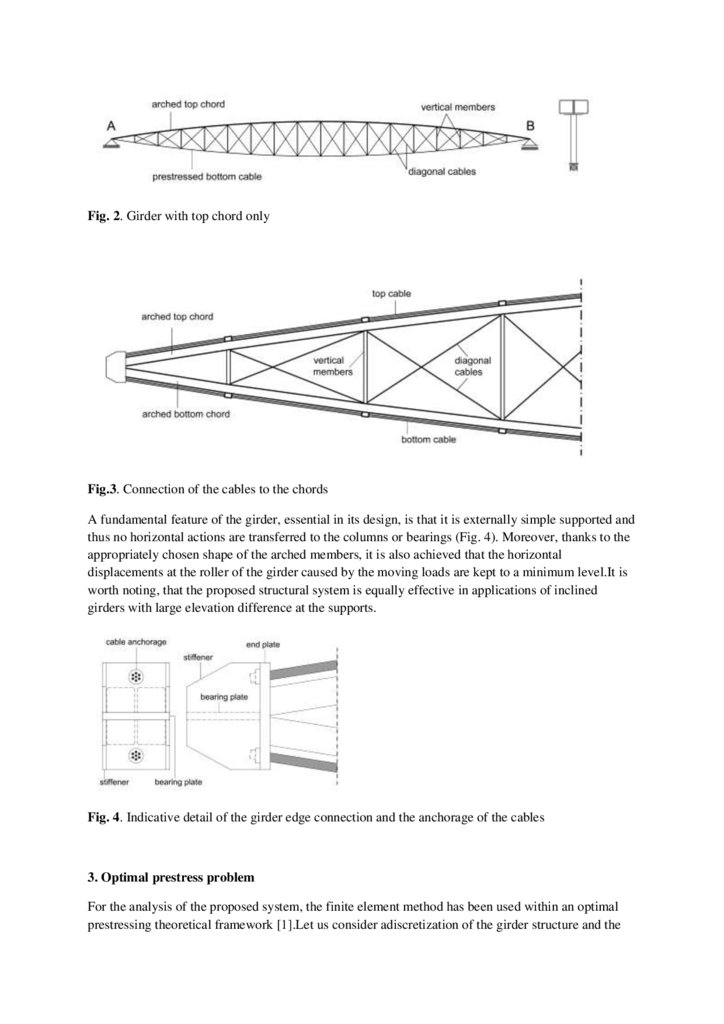
external prestressed cables adjacent to either chord of the girder. These cablesare in contact with the
chords,having the same geometry, and are anchored at the edges of the girder (Fig. 3).Their role is
firstly to increase the stiffness of the structure and secondly due to the prestress to produce
verticalreactions at the struts that counteract external loading.
Fig.1. Girder with top and bottom chord
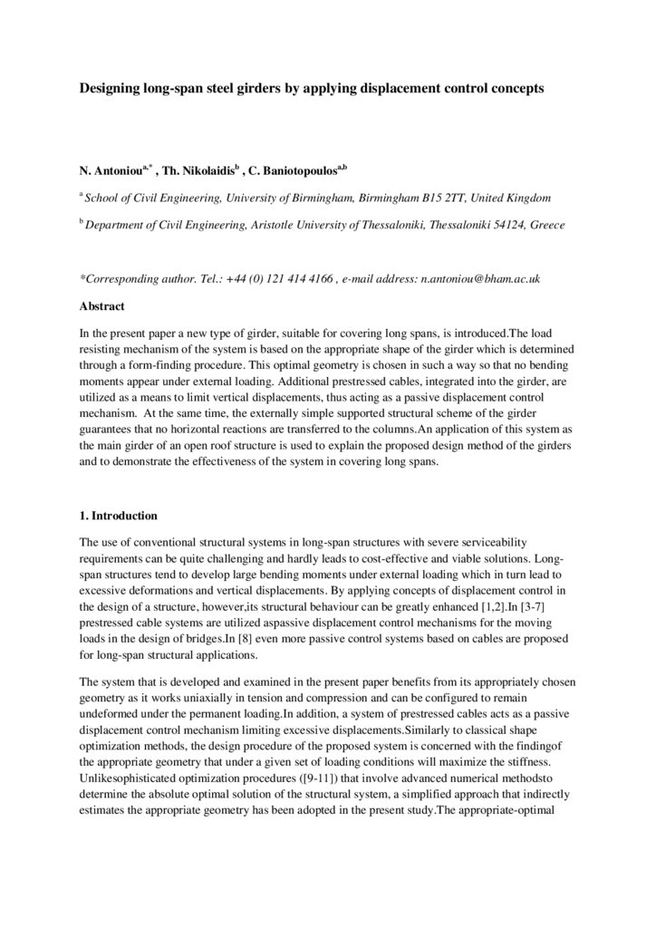
In the case of small anticipated upward actions the system can be further modified by completely
removing the bottom chord, thus significantly reducing the weight of the structure. In this variation of
the system (Fig. 2), the girder consists only of an arched top chord which is supported from
underneath by an external prestressed polygonal cable of negative curvature (concave facing
upwards). The cable is anchored at the edges of the arched member and its polygonal shape is
imposed by a series of vertical struts of appropriate length that are rigidly connected to the top chord.
Like in the first variation of the girder, stabilizing diagonal cables connect the bottom and top part of
successive struts.This system with the arched top chord and the polygonal prestressed bottom cable
has been shown to perform well under downward actions in previous studies [12] and the present
paper focuses on the analysis of the first variation of the girder.
3.
Fig. 2. Girder with top chord onlyFig.3. Connection of the cables to the chords
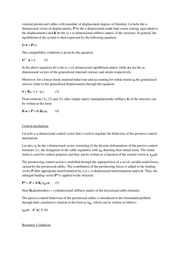
A fundamental feature of the girder, essential in its design, is that it is externally simple supported and
thus no horizontal actions are transferred to the columns or bearings (Fig. 4). Moreover, thanks to the
appropriately chosen shape of the arched members, it is also achieved that the horizontal
displacements at the roller of the girder caused by the moving loads are kept to a minimum level.It is
worth noting, that the proposed structural system is equally effective in applications of inclined
girders with large elevation difference at the supports.
Fig. 4. Indicative detail of the girder edge connection and the anchorage of the cables
3. Optimal prestress problem
For the analysis of the proposed system, the finite element method has been used within an optimal
prestressing theoretical framework [1].Let us consider adiscretization of the girder structure and the
4.
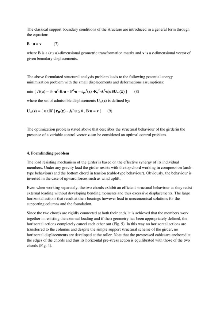
external prestressed cables with nnumber of displacement degrees of freedom. Let u be the ndimensional vector of displacements, P be the n-dimensional nodal load vector (energy equivalent tothe displacements) and K be the (n x n)-dimensional stiffness matrix of the structure. In general, the
equilibrium of the system is then expressed by the following equation:
G∙σ = P(1)
The compatibility condition is given by the equation:
GT ∙ u = ε
(2)
In the above equations G is the (n x m)-dimensional equilibrium matrix while σ,ε are the mdimensional vectors of the generalized (internal) stresses and strains respectively.
Moreover, for a linear elastic material behaviour and accounting for initial strains ε0 the generalized
stresses relate to the generalized displacements through the equation:
σ = K0 ∙ ( ε - ε0 )
(3)
From relations (1), (2) and (3), after simple matrix manipulationsthe stiffness Κ of the structure can
be written in the form:
K∙u = P + G∙K0∙ε0
(4)
Control mechanism
Let z be a q-dimensional control vector that is used to regulate the behaviour of the prestress control
mechanism.
Let also, εc be the s-dimensional vector consisting of the discrete deformations of the passive control
elements (i.e. the elongation of the cable segments) with εpr denoting their initial strain. The initial
strain is used for control purposes and thus can be written as a function of the control vector z, εpr(z).
The prestressing control action is modelled through the superposition of a set of variable nodal forces
caused by the prestressed cables. The contribution of the prestressing forces is added to the loading
vector P after appropriate transformation by a (n x s)-dimensional transformation matrixA. Thus, the
enlarged loading vector P* is applied to the structure:
P* = P + A∙Kc∙εpr(z)
(5)
Here Kcdenotesthe(s x s)-dimensional stiffness matrix of the discretized cable elements.
The passive control behaviour of the prestressed cables is introduced to the formulated problem
through their constitutive relation in the form εc>εpr, which can be written as follows:
εpr(z) - AT∙u≤ 0 (6)
Boundary Conditions
5.
The classical support boundary conditions of the structure are introduced in a general form throughthe equation:
B∙u=v
(7)
where B is a (r x n)-dimensional geometric transformation matrix and v is a r-dimensional vector of
given boundary displacements.
The above formulated structural analysis problem leads to the following potential energy
minimization problem with the small displacements and deformations assumptions:
min { Π(u) = ½ ∙uT∙K∙u – PT∙u – εprT(z) ∙KcT∙AT∙u|u∈Uad(z) }
(8)
where the set of admissible displacements Uad(z) is defined by:
Uad(z) = { u∈ℝn | εpr(z) – AT∙u ≤ 0 , B∙u = v }
(9)
The optimization problem stated above that describes the structural behaviour of the girderin the
presence of a variable control vector z can be considered an optimal control problem.
4. Formfinding problem
The load resisting mechanism of the girder is based on the effective synergy of its individual
members. Under any gravity load the girder resists with the top chord working in compression (archtype behaviour) and the bottom chord in tension (cable-type behaviour). Obviously, the behaviour is
inverted in the case of upward forces such as wind uplift.
Even when working separately, the two chords exhibit an efficient structural behaviour as they resist
external loading without developing bending moments and thus excessive displacements. The large
horizontal actions that result at their bearings however lead to uneconomical solutions for the
supporting columns and the foundation.
Since the two chords are rigidly connected at both their ends, it is achieved that the members work
together in resisting the external loading and if their geometry has been appropriately defined, the
horizontal actions completely cancel each other out (Fig. 5). In this way no horizontal actions are
transferred to the columns and despite the simple support structural scheme of the girder, no
horizontal displacements are developed at the roller. Note that the prestressed cablesare anchored at
the edges of the chords and thus its horizontal pre-stress action is equilibrated with those of the two
chords (Fig. 4).
6.
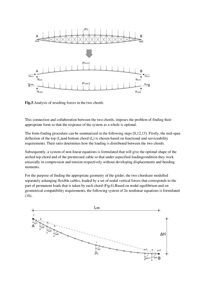
Fig.5.Analysis of resulting forces in the two chordsThis connection and collaboration between the two chords, imposes the problem of finding their
appropriate form so that the response of the system as a whole is optimal.
The form-finding procedure can be summarized in the following steps [8,12,13]. Firstly, the mid-span
deflection of the top (fo)and bottom chord (fu) is chosen based on functional and serviceability
requirements. Their ratio determines how the loading is distributed between the two chords.
Subsequently, a system of non-linear equations is formulated that will give the optimal shape of the
arched top chord and of the prestressed cable so that under aspecified loadingcondition they work
uniaxially in compression and tension respectively without developing displacements and bending
moments.
For the purpose of finding the appropriate geometry of the girder, the two chordsare modelled
separately ashanging flexible cables, loaded by a set of nodal vertical forces that corresponds to the
part of permanent loads that is taken by each chord (Fig.6).Based on nodal equilibrium and on
geometrical compatibility requirements, the following system of 2n nonlinear equations is formulated
(10).
7.
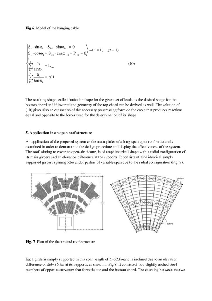
Fig.6. Model of the hanging cableSi sinω i Si 1 sinω i 1 0
i 1,...,(n 1)
S
cosω
S
cosω
P
0
i
i
i
1
i
1
i
1
n
ai
L arc
i 1 sinω i
n a
i ΔΗ
i 1 tanω i
(10)
The resulting shape, called funicular shape for the given set of loads, is the desired shape for the
bottom chord and if inverted the geometry of the top chord can be derived as well. The solution of
(10) gives also an estimation of the necessary prestressing force on the cable that produces reactions
equal and opposite to the forces used for the determination of its shape.
5. Application in an open roof structure
An application of the proposed system as the main girder of a long-span open roof structure is
examined in order to demonstrate the design procedure and display the effectiveness of the system.
The roof, aiming to cover an open-air theatre, is of amphithatrical shape with a radial configuration of
its main girders and an elevation difference at the supports. It consists of nine identical simply
supported girders spaning 72m andof purlins of variable span due to the radial configuration (Fig. 7).
Fig. 7. Plan of the theatre and roof-structure
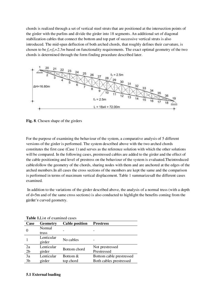
Each girderis simply supported with a span length of L=72.0mand is inclined due to an elevation
difference of ΔΗ=16.8m at its supports, as shown in Fig.8. It consistsof two slightly arched steel
members of opposite curvature that form the top and the bottom chord. The coupling between the two
8.
chords is realized through a set of vertical steel struts that are positioned at the intersection points ofthe girder with the purlins and divide the girder into 18 segments. An additional set of diagonal
stabilization cables that connect the bottom and top part of successive vertical struts is also
introduced. The mid-span deflection of both arched chords, that roughly defines their curvature, is
chosen to be fo=fu=2.5m based on functionality requirements. The exact optimal geometry of the two
chords is determined through the form finding procedure described later.
Fig. 8. Chosen shape of the girders
For the purpose of examining the behaviour of the system, a comparative analysis of 5 different
versions of the girder is performed. The system described above with the two arched chords
constitutes the first case (Case 1) and serves as the reference solution with which the other solutions
will be compared. In the following cases, prestressed cables are added to the girder and the effect of
the cable positioning and level of prestress on the behaviour of the system is evaluated.Theintroduced
cablesfollow the geometry of the chords, sharing nodes with them and are anchored at the edges of the
arched members.In all cases the cross sections of the members are kept the same and the comparison
is performed in terms of maximum vertical displacement. Table 1 summarizesall the different cases
examined.
In addition to the variations of the girder described above, the analysis of a normal truss (with a depth
of d=5m and of the same cross sections) is also conducted to highlight the benefits coming from the
girder’s curved geometry.
Table 1.List of examined cases
Case Geometry Cable position
Normal
0
truss
Lenticular
1
No cables
girder
2a
Lenticular
Bottom chord
2b
girder
3a
Lenticular
Bottom &
3b
girder
top chord
5.1 External loading
Prestress
Not prestressed
Prestressed
Bottom cable prestressed
Both cables prestressed
9.
The external loading is applied as a set of nodal forces acting directly on the nodes of the upper chordand representsthe reactions of the purlins and the self-weight of the girder which is considered to be
concentrated in these nodes.Due to the radial configuration and the convergence of the girders the
tributary area of each node is not constant resulting in a non-uniform loading of the structure. All the
loads and their combinations are calculated according to the Eurocodes and include the self-weight as
well as snow and wind action.
Three load cases are considered in the present analysis: 1) Dead load only (C1). 2) A combination of
dead load, snow and wind (C2). 3) A combination of dead load and wind uplift (C3). The later two
load cases constitute the most severe downward and upward actionrespectively (Fig. 9).
Fig. 9. Variation of nodal forces for each load case considered
5.2 Form finding of the girders
The exactoptimal geometry of the girder(incorporated in all the examined girder variations) is
determined by solving the system of the 2n nonlinear equilibrium equations for each chord, where n is
the number of the girder segments. The external nodal forces introduced into the equations are thoseof
the dead load case and due to the same curvature chosen for the two chords (expressed by the chosen
mid-span deflection of 2.5m) the loading is distributed equally between them (50% of loading on
each). The solution of the nonlinear system was calculated in the present example using the
MATLAB software package.
Apart from the optimal shape (shown in Fig. 8), the solution of the equations givesalso the necessary
prestressing force on the cable that produces upward reactionsthat negate the external dead load. Note
that the redundant length of the cable due to the prestressing can be removed during this initial stage
when anchoring it at the extreme points of the girder.
10.
5.3 Structural analysis of the girdersThe statically indeterminate structural problem that is formulated can be solved by any available nonlinear structural analysis software. In this example the ABAQUS general purpose FEA software
wasemployed.
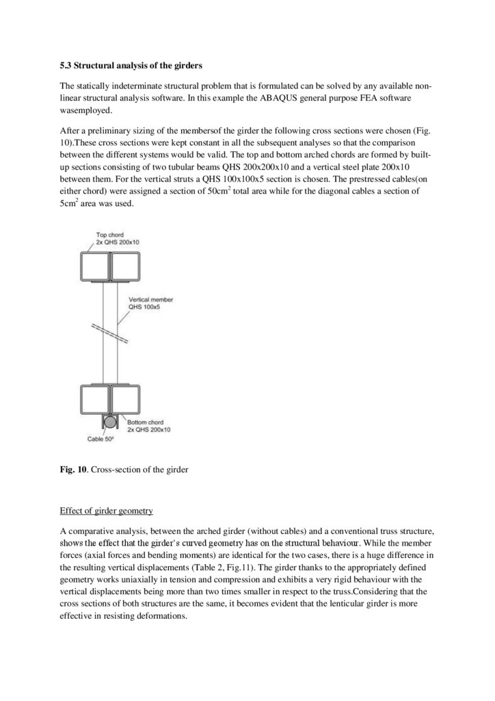
After a preliminary sizing of the membersof the girder the following cross sections were chosen (Fig.
10).These cross sections were kept constant in all the subsequent analyses so that the comparison
between the different systems would be valid. The top and bottom arched chords are formed by builtup sections consisting of two tubular beams QHS 200x200x10 and a vertical steel plate 200x10
between them. For the vertical struts a QHS 100x100x5 section is chosen. The prestressed cables(on
either chord) were assigned a section of 50cm2 total area while for the diagonal cables a section of
5cm2 area was used.
Fig. 10. Cross-section of the girder
Effect of girder geometry
A comparative analysis, between the arched girder (without cables) and a conventional truss structure,
shows the effect that the girder’s curved geometry has on the structural behaviour. While the member
forces (axial forces and bending moments) are identical for the two cases, there is a huge difference in
the resulting vertical displacements (Table 2, Fig.11). The girder thanks to the appropriately defined
geometry works uniaxially in tension and compression and exhibits a very rigid behaviour with the
vertical displacements being more than two times smaller in respect to the truss.Considering that the
cross sections of both structures are the same, it becomes evident that the lenticular girder is more
effective in resisting deformations.
11.
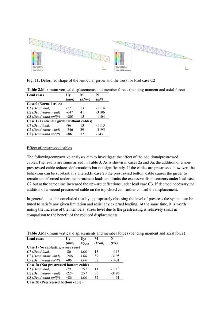
Fig. 11. Deformed shape of the lenticular girder and the truss for load case C2Table 2.Maximum vertical displacements and member forces (bending moment and axial force)
Load cases
Uy
(mm)
M
(kNm)
Case 0 (Normal truss)
C1 (Dead load)
-221
13
C2 (Dead-snow-wind)
-647
41
C3 (Dead-wind uplift)
+203
15
Case 1 (Lenticular girder without cables)
C1 (Dead load)
-86
13
C2 (Dead-snow-wind)
-246
39
C3 (Dead-wind uplift)
+86
32
N
(kN)
-1114
-3196
-1104
-1113
-3195
-1431
Effect of prestressed cables
The followingcomparative analyses aim to investigate the effect of the additionalprestressed
cables.The results are summarized in Table 3. As is shown in cases 2a and 3a, the addition of a nonprestressed cable reduces deformations but not significantly. If the cables are prestressed however, the
behaviour can be substantially altered.In case 2b the prestressed bottom cable causes the girder to
remain undeformed under the permanent loads and limits the excessive displacements under load case
C2 but at the same time increased the upward deflections under load case C3. If deemed necessary,the
addition of a second prestressed cable on the top chord can further control the displacement.
In general, it can be concluded that by appropriately choosing the level of prestress the system can be
tuned to satisfy any given limitation and resist any external loading. At the same time, it is worth
noting the increase of the members’ stress level due to the prestressing is relatively small in
comparison to the benefit of the reduced displacements.
Table 3.Maximum vertical displacements and member forces (bending moment and axial force)
Load cases
Uy
Uy/
(mm)
Uy,ref
Case 1 (No cables)(reference case)
C1 (Dead load)
-86
1.00
C2 (Dead-snow-wind)
-246
1.00
C3 (Dead-wind uplift)
+86
1.00
Case 2a (Not prestressed bottom cable)
C1 (Dead load)
-79
0.92
C2 (Dead-snow-wind)
-224
0.91
C3 (Dead-wind uplift)
+86
1.00
Case 2b (Prestressed bottom cable)
M
(kNm)
N
(kN)
13
39
32
-1113
-3195
-1431
11
36
32
-1113
-3196
-1431
12.
C1 (Dead load)0
0.00
0.2
-1127
C2 (Dead-snow-wind)
-144
0.59
25
-3206
C3 (Dead-wind uplift)
+156
1.81
41
-1876
Case 3a (Prestressed bottom & not prestressed top cable)
C1 (Dead load)
0
0.00
0.2
-1127
C2 (Dead-snow-wind)
-144
0.59
25
-3206
C3 (Dead-wind uplift)
+141
1.64
40
-1880
Case 3b (Prestressed bottom & top cable)
C1 (Dead load)
-35
0.41
5
-1581
C2 (Dead-snow-wind)
-166
0.67
28
-3287
C3 (Dead-wind uplift)
+106
1.23
35
-1992
6. Summary and conclusion
It is shown, that the herein introduced structural system can be effectively used to form a long-span
roof structure and can give satisfactory results to a problem of severe loading conditions and stringent
design parameters.Long-span structures usually face the problem of developing high bending
moments that lead to strong and heavy cross-sections and to complex uneconomical solutions not
suitable for medium scale projects.The proposed girders thanks to their appropriate shape derived
from the form-finding procedure and the effective synergy of its individual members work mainly in
tension and compression without developing significant bending moments. In addition, introducing
prestressed cablestangent to the chords of the girder and by choosing the appropriate level of
prestress, the system can be calibrated to produce any desired set of vertical cable reactions (upwards
or downwards) that will counteract the external loading and thus limit the vertical displacements. In
essence, the cables act as a displacement control mechanism and contribute a decrease of the required
cross-sections, resulting in lighter structures and economy of resources.
More importantly, a roof structure formed by girders of the proposed type has the advantage of not
being in its manufacturing and erection phases much different to a conventional steel structure.In this
sense, both the design and the construction of such structures can be standardized to a certain degree
thus leading to a structural system that exhibits notable application potentiality.
References
[1]
Bisbos CD. Optimal control of structures. Doctoral dissertation. Thessaloniki (Greece):
Department of Civil Engineering, Aristotle University; 1982 (in Greek)
[2]
Michalopoulos A. Application of external prestressing on steel and composite structures.
Doctoral dissertation. Thessaloniki (Greece): Department of Civil Engineering, Aristotle University;
1991 (in Greek)
[3]
Michalopoulos A, Stavroulakis GE, Zacharenakis E, Panagiotopoulos PD. A prestressed
tendon based passive control system for bridges. Computers and Structures 1997;63(6):1165-75
[4]
Stavroulakis GE, Michalopoulos A, Panagiotopoulos PD, Zacharenakis E. A multiblock
unilateral concept for passive control of prestressed bridges. Structural Multidisciplinary Optimization
2000;19:225-36
[5]
Michalopoulos A, Nikolaidis Th, Stavroulakis GE, Baniotopoulos CC. Passive control of
bridges: The double cable net method. Engineering Structures 2005;27(13):1835-42.
13.
[6]Michalopoulos A, Nikolaidis Th, Stavroulakis GE, Baniotopoulos CC. Passive control of
bridges. Jordan Journal of Civil Engineering 2007;1(2):173-85.
[7]
Nikolaidis Th, Michalopoulos A, Stavroulakis GE, Baniotopoulos CC. Bridges with
composite deck supported by prestressed cables: The MNB optimal control system. Pollack Periodica
2007;2(2):103-17.
[8]
Nikolaidis Th. Displacement control systems for large span structures using cable nets.
Doctoral dissertation. Thessaloniki (Greece):Department of Civil Engineering, Aristotle University;
2003 (in Greek)
[9]
Bendsoe MP, Sigmund O. Topology optimization. Theory, methods and applications.
Berlin:Springer; 2003
[10]
Eschenauer H, Olhoff N, Schnell W. Applied structural mechanics. Berlin:Springer; 1997
[11]
Panagiotopoulos PD. Inequality problems in mechanics and applications. Convex and
nonconvex energy functions. Boston:Birkhäuser; 1985
[12]
Michalopoulos A, Nikolaidis Th, Stavroulakis GE, Baniotopoulos CC. Displacement control
of large span steel beams by means of cables. Proceedings of the 6th National (Greek) Metal
Structures Conference 2008:450-456. (in Greek)
[13]
Antoniou N, Nikolaidis Th, Michalopoulos A, Baniotopoulos CC. Displacement control of
large span steel girders using cables: Prospect of application in an open roof. Proceedings of the 7th
National (Greek) Metal Structures Conference 2011:396-403. (in Greek)