


 Construction
Similar presentations:
")


School of building and environment. Department of civil engineering
1.
SCHOOL OF BUILDING AND ENVIRONMENTDEPARTMENT OF CIVIL ENGINEERING
UNIT – I – STRUCTURAL ANALYSIS II – SCI1307
2.
UNIT IROLLING LOADS
Rolling loads are those loads which roll over the given structural element from
one endto another. You can see many live examples of rolling loads, like a train on the
railway track, vehicles on the bridges or roads are rolling loads.
The maximum moment occurs at a point of zero shears.
For beams loaded with concentrated loads, the point of zero shears usually
occurs under a concentrated load and so the maximum moment.
Beams and girders such as in a bridge or an overhead crane are subject to
moving concentrated loads, which are at fixed distance with each other.
The problem here is to determine the moment under each load when each load
is in a position to cause a maximum moment. The largest value of these
moments governs the design of the beam
Now to analyze the given structural element for the rolling loads, which classify these
rollingloads into the following classes:
(1) Single point rolling loads
(2) Uniformly distributed rolling loads, - a) shorter than span b) Longer than span.
(3) Two point loads at a fixed distance apart.
(4) Several point loads at fixed distance apart.
Single point load: If a single point concentrated load moves from one end of a
girder toanother end of it, it becomes necessary to find out the maximum values of the
shear forces and bending moments at every section of the girder to produce an economical
and safe design.
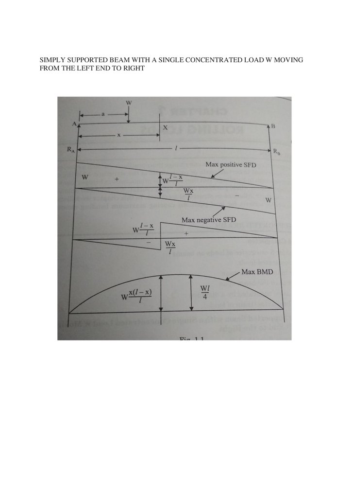
Now if we analyse the girder then you will find that at any section on the girder
maximumnegative shear force induces when the point load is just on the left of that
section, and maximum.
Positive shear force is induced if the load is just on the right of the section.
3.
Absolute maximum negative shear force is produced at the right end of the girder andabsolutemaximum shear force is produced at the left end of the section.
Bending moment is positive for any position of the load, but maximum bending moment at
a section occurs when the load is on the section itself and absolute maximum bending
moment isproduced at the central section when load is also at the center.
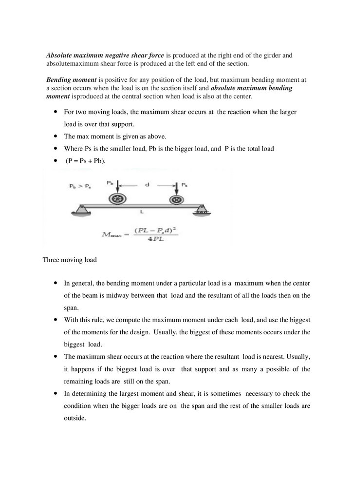
For two moving loads, the maximum shear occurs at the reaction when the larger
load is over that support.
The max moment is given as above.
Where Ps is the smaller load, Pb is the bigger load, and P is the total load
(P = Ps + Pb).
Three moving load
In general, the bending moment under a particular load is a maximum when the center
of the beam is midway between that load and the resultant of all the loads then on the
span.
With this rule, we compute the maximum moment under each load, and use the biggest
of the moments for the design. Usually, the biggest of these moments occurs under the
biggest load.
The maximum shear occurs at the reaction where the resultant load is nearest. Usually,
it happens if the biggest load is over that support and as many a possible of the
remaining loads are still on the span.
In determining the largest moment and shear, it is sometimes necessary to check the
condition when the bigger loads are on the span and the rest of the smaller loads are
outside.
4.
SIMPLY SUPPORTED BEAM WITH A SINGLE CONCENTRATED LOAD W MOVINGFROM THE LEFT END TO RIGHT
5.
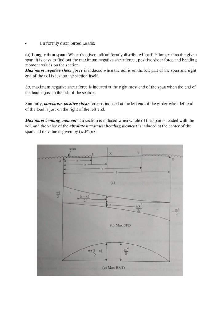
Uniformly distributed Loads:
(a) Longer than span: When the given udl(uniformly distributed load) is longer than the given
span, it is easy to find out the maximum negative shear force , positive shear force and bending
moment values on the section.
Maximum negative shear force is induced when the udl is on the left part of the span and right
end of the udl is just on the section itself.
So, maximum negative shear force is induced at the right most end of the span when the end of
the load is just to the left of the section.
Similarly, maximum positive shear force is induced at the left end of the girder when left end
of the load is just on the right of the left end.
Maximum bending moment at a section is induced when whole of the span is loaded with the
udl, and the value of the absolute maximum bending moment is induced at the center of the
span and its value is given by (w.l^2)/8.
6.
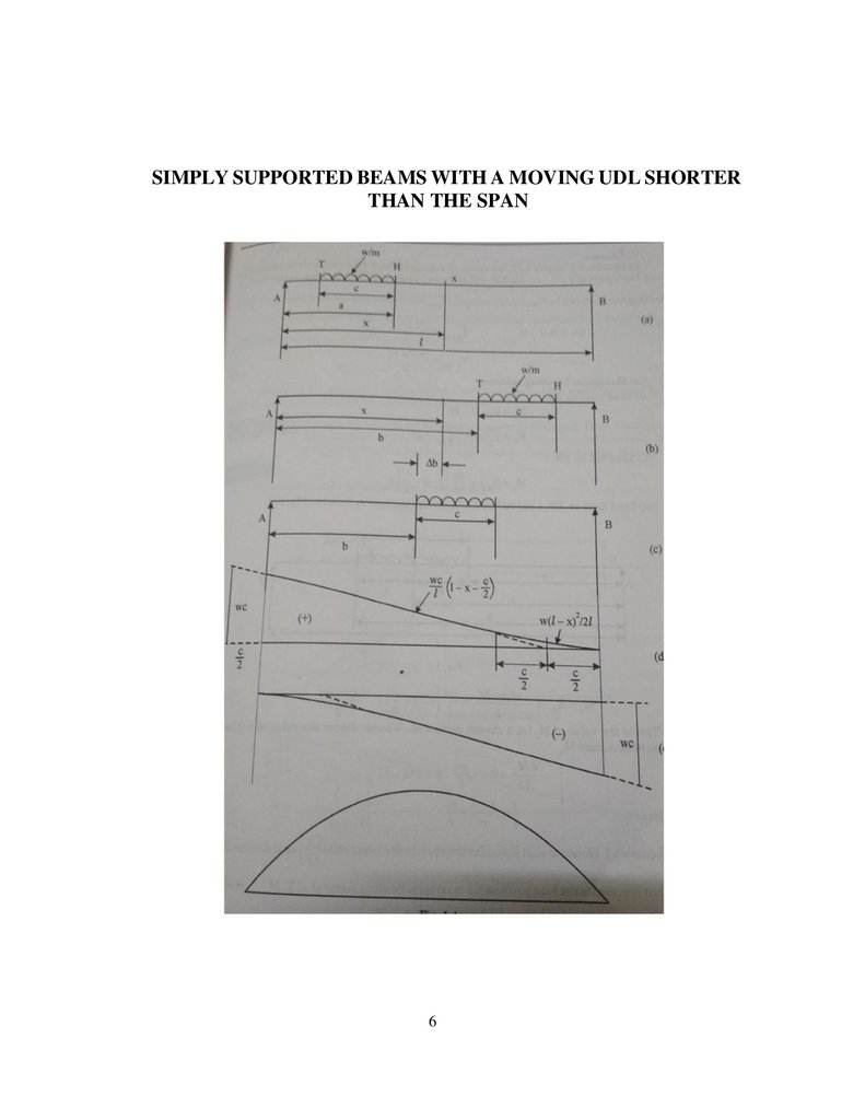
SIMPLY SUPPORTED BEAMS WITH A MOVING UDL SHORTERTHAN THE SPAN
6
7.
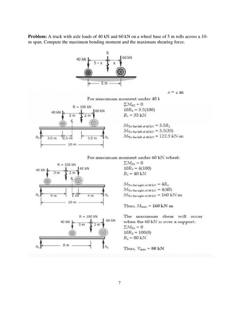
Problem: A truck with axle loads of 40 kN and 60 kN on a wheel base of 5 m rolls across a 10m span. Compute the maximum bending moment and the maximum shearing force.7
8.
SCHOOL OF BUILDING AND ENVIRONMENTDEPARTMENT OF CIVIL ENGINEERING
UNIT – II – STRUCTURAL ANALYSIS II – SCI1307
1
9.
UNIT-IIINFLUENCE LINESDETERMINATE AND NDETERMINATESTRUCTURES
2.1 Definitions of influence line
An influence line is a diagram whose ordinates, which are plotted as a function of
distance along the span, give the value of an internal force, a reaction, or a
displacement at a particular point in a structure as a unit load move across the
structure.
An influence line is a curve the ordinate to which at any point equals the value of
some particular function due to unit load acting at that point.
An influence line represents the variation of either the reaction, shear, moment, or
deflection at a specific point in a member as a unit concentrated force moves over
the member.
For example, we can construct influence lines for (shear force at B ) or (bending moment at) or
(vertical reaction at support D ) and each one will help us calculate the corresponding response
parameter for different sets of loading on the beam AD (Figure 2).
An influence line is a diagram which presents the variation of a certain response parameter due to
the variation of the position of a unit concentrated load along the length of the structural member.
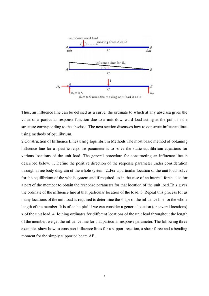
Let us consider that a unit downward concentrated force is moving from point A to point B of the
beam shown in Figure 3a. We can assume it to be a wheel of unit weight moving along the length
of the beam. The magnitude of the vertical support reaction at A will change depending on the
location of this unit downward force. The influence line for (Figure3b) gives us the value of for
different locations of the moving unit load. From the ordinate of the influence line at C, we can say
that when the unit load is at point C.
2
10.
Thus, an influence line can be defined as a curve, the ordinate to which at any abscissa gives thevalue of a particular response function due to a unit downward load acting at the point in the
structure corresponding to the abscissa. The next section discusses how to construct influence lines
using methods of equilibrium.
2 Construction of Influence Lines using Equilibrium Methods The most basic method of obtaining
influence line for a specific response parameter is to solve the static equilibrium equations for
various locations of the unit load. The general procedure for constructing an influence line is
described below. 1. Define the positive direction of the response parameter under consideration
through a free body diagram of the whole system. 2..For a particular location of the unit load, solve
for the equilibrium of the whole system and if required, as in the case of an internal force, also for
a part of the member to obtain the response parameter for that location of the unit load.This gives
the ordinate of the influence line at that particular location of the load. 3. Repeat this process for as
many locations of the unit load as required to determine the shape of the influence line for the whole
length of the member. It is often helpful if we can consider a generic location (or several locations)
x of the unit load. 4. Joining ordinates for different locations of the unit load throughout the length
of the member, we get the influence line for that particular response parameter. The following three
examples show how to construct influence lines for a support reaction, a shear force and a bending
moment for the simply supported beam AB.
3
11.
Draw the influence line for (vertical reaction at A ) of beam AB in Fig.11) A system of concentrated load, role beam left to right, s.s beam span of 10m and 10 KNload
leading
Find
1.Absolute max +ve S.F
2. .Absolute max -ve S.F
3..Absolute max BM
Solution
1. Absolute max +ve S.F
Using the similar triangle method and we get the x, y & z values
X
=
0.85 m
Y
=
0.75 m
Z
=
0.55 m
S.F
=
(10×1)+(15×0.83)+(20×0.75)+(10×0.55)
=
43.25 KN
4
12.
Using the similar triangle method and we get the l, m, n & o valuesL=0.8 mM
=
0.65 m
N
=
0.55 m
O
=
0.35 m
S.F
=
(20×1)+(10×0.8)+(15×0.65)+(20×0.55)+(10×0.35)
=
52.25 KN
Absolute max -ve S.F
Using the similar triangle method and we get the l, m, n & o values
L
=
0.35 m
5
13.
M=
0.55 m
N
=
0.7 m
O
=
0.8 m
S.F
=
(10×1)+(20×0.8)+(15×0.7)+(10×0.55)+(20×0.35)
=
- 49 KN
6
14.
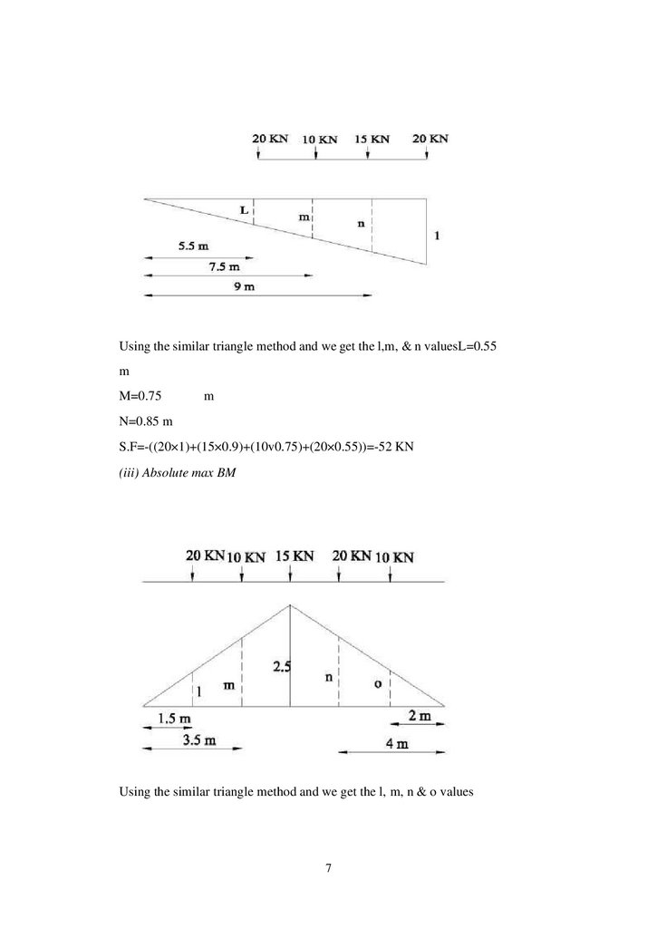
Using the similar triangle method and we get the l,m, & n valuesL=0.55m
M=0.75
m
N=0.85 m
S.F=-((20×1)+(15×0.9)+(10v0.75)+(20×0.55))=-52 KN
(iii) Absolute max BM
Using the similar triangle method and we get the l, m, n & o values
7
15.
L=
0.75 m
M
=
1.75 m
N
=
2m
O
=
1m
Max BM
=
(20×0.75) +(10×1.75)+(15×2.5)+(20×2)+(10×1)
=
22.75 KN
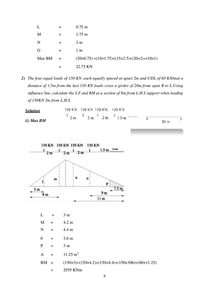
2) The four equal loads of 150 KN ,each equally spaced at apart 2m and UDL of 60 KN/mat a
distance of 1.5m from the last 150 KN loads cross a girder of 20m from span R to L.Using
influence line ,calculate the S.F and BM at a section of 8m from L.H.S support when leading
of 150KN 5m from L.H.S.
Solution
(i) Max BM
L
=
3m
M
=
4.2 m
N
=
4.4 m
0
=
3.6 m
P
=
3m
A
=
11.25 m2
BM =
=
(150×3)+(150×4.2)+(150×4.4)+(150×306)+(60×11.25)
2955 KNm
8
16.
ii) Shear ForceCompute maximum end shear for the given beam loaded with moving loads as shown inFigure
L =
0.25 m,
M =
0.3 m,
N =
0.55 m,
O =
0.45 m,
P =
0.375 m
SF =
((150×0.25)+(150×0.35)+(150×0.55)+(150×0.45)+(60×1.41))
=
144. KN
9
17.
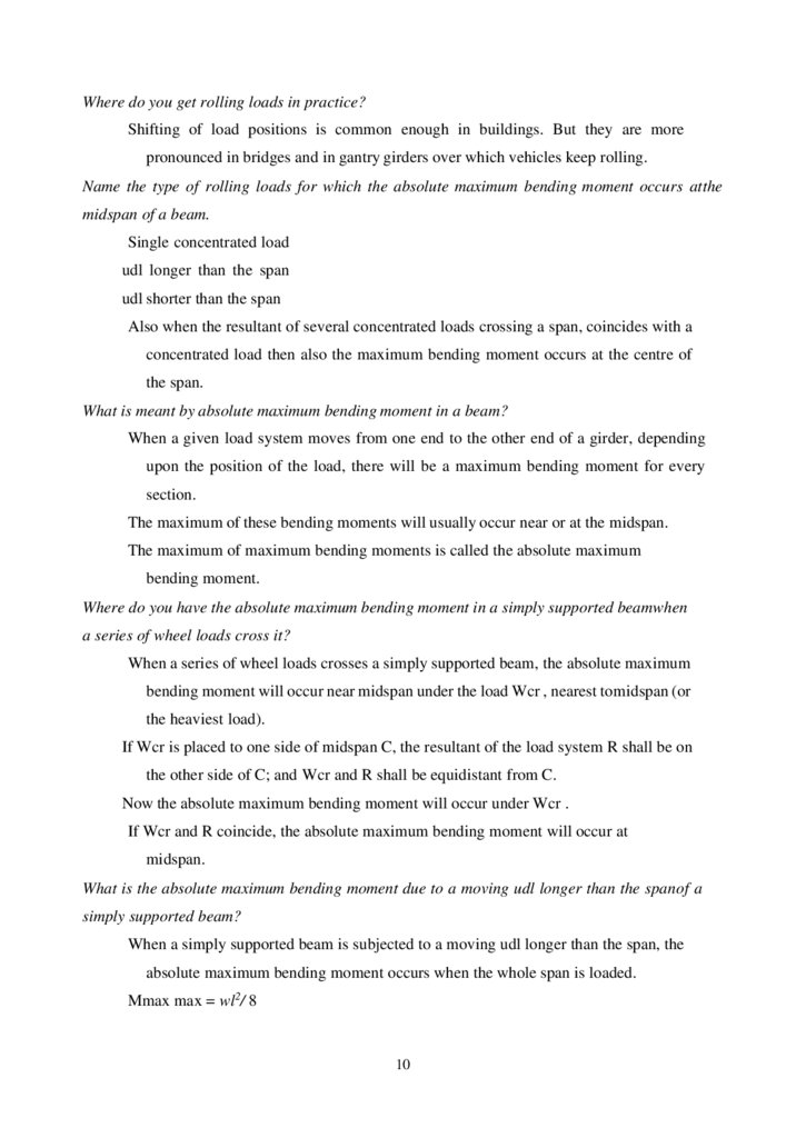
Where do you get rolling loads in practice?Shifting of load positions is common enough in buildings. But they are more
pronounced in bridges and in gantry girders over which vehicles keep rolling.
Name the type of rolling loads for which the absolute maximum bending moment occurs at the
midspan of a beam.
Single concentrated load
udl longer than the span
udl shorter than the span
Also when the resultant of several concentrated loads crossing a span, coincides with a
concentrated load then also the maximum bending moment occurs at the centre of
the span.
What is meant by absolute maximum bending moment in a beam?
When a given load system moves from one end to the other end of a girder, depending
upon the position of the load, there will be a maximum bending moment for every
section.
The maximum of these bending moments will usually occur near or at the midspan.
The maximum of maximum bending moments is called the absolute maximum
bending moment.
Where do you have the absolute maximum bending moment in a simply supported beamwhen
a series of wheel loads cross it?
When a series of wheel loads crosses a simply supported beam, the absolute maximum
bending moment will occur near midspan under the load Wcr , nearest to midspan (or
the heaviest load).
If Wcr is placed to one side of midspan C, the resultant of the load system R shall be on
the other side of C; and Wcr and R shall be equidistant from C.
Now the absolute maximum bending moment will occur under Wcr .
If Wcr and R coincide, the absolute maximum bending moment will occur at
midspan.
What is the absolute maximum bending moment due to a moving udl longer than the span of a
simply supported beam?
When a simply supported beam is subjected to a moving udl longer than the span, the
absolute maximum bending moment occurs when the whole span is loaded.
Mmax max = wl2/ 8
10
18.
State the location of maximum shear force in a simple beam with any kind of loading.In a simple beam with any kind of load, the maximum positive shear force occurs at theleft
hand support and maximum negative shear force occurs at right hand support.
What is meant by maximum shear force diagram?
Due to a given system of rolling loads the maximum shear force for every section of the
girder can be worked out by placing the loads in appropriate positions.
When these are plotted for all the sections of the girder, the diagram that we obtain is
the maximum shear force diagram.
This diagram yields the ‘design shear’ for each cross section.
What is meant by influence lines?
An influence line is a graph showing, for any given frame or truss, the variation of any
force or displacement quantity (such as shear force, bending moment, tension,
deflection) for all positions of a moving unit load as it crosses the structure from one
end to the other.
What are the uses of influence line diagrams?
Influence lines are very useful in the quick determination of reactions, shear force,
bending moment or similar functions at a given section under any given system of
moving loads and
Influence lines are useful in determining the load position to cause maximum value of a
given function in a structure on which load positions can vary.
Draw the influence line diagram for shear force at a point X in a simply supported beam AB
of span ‘ l’ m.
Draw the ILD for bending moment at any section X of a simply supported beam and mark
the ordinates.
11
19.
What do you understand by the term reversal of stresses?In certain long trusses the web members can develop either tension or compression
depending upon the position of live loads.
This tendancy to change the nature of stresses is called reversal of stresses.
State Muller-Breslau principle.
Muller-Breslau principle states that, if we want to sketch the influence line for any
force quantity (like thrust, shear, reaction, support moment or bending moment) in a
structure,
We remove from the structure the resistant to that force quantity and
We apply on the remaining structure a unit displacement corresponding to that force
quantity.
The resulting displacements in the structure are the influence line ordinates sought.
State Maxwell-Betti’ s theorem.
In a linearly elastic structure in static equilibrium acted upon by either of two systems
of external forces, the virtual work done by the first system of forces in undergoing the
displacements caused by the second system of forces is equal to the virtual work done
by the second system of forces in undergoing the displacements caused by the first
system of forces.
Maxwell Betti’s theorem helps us to draw influence lines for structures.
What is the necessity of model analysis?
When the mathematical analysis of problem is virtually impossible.
Mathematical analysis though possible is so complicated and time consuming that the
model analysis offers a short cut.
The importance of the problem is such that verification of mathematical analysis by
an actual test is essential.
Define similitude.
Similitude means similarity between two objects namely the model and the prototype
with regard to their physical characteristics:
12
20.
▪Geometric similitude is similarity of form
▪
Kinematic similitude is similarity of motion
▪
Dynamic and/or mechanical similitude is similarity of masses and/or
forces.
State the principle on which indirect model analysis is based.
The indirect model analysis is based on the Muller Breslau principle.
Muller Breslau principle has lead to a simple method of using models of structures to
get the influence lines for force quantities like bending moments, support moments,
reactions, internal shears, thrusts, etc.,
To get the influence line for any force quantity,
▪
(i) remove the resistant due to the force,
▪
(ii) apply a unit displacement in the direction
▪
(iii) plot the resulting displacement diagram.
This diagram is the influence line for the force.
What is the principle of dimensional similarity?
Dimensional similarity means geometric similarity of form.
This means that all homologous dimensions of prototype and model must be in some
constant ratio.
What is Begg’ s deformeter?
Begg’s deformeter is a device to carry out indirect model analysis on structures.
It has the facility to apply displacement corresponding to moment, shear or thrust at
any desired point in the model.
In addition, it provides facility to measure accurately the consequent displacements all
over the model.
Name any four model making materials.
Perspex,
plexiglass,
acrylic,
plywood,
sheet araldite
bakelite
Micro-concrete,
mortar and plaster of paris
13
21.
Wh at is ‘ dumm y lengt h ’ in m odels tested wit h Begg’ s def orm eter.Dummy length is the additional length (of about 10 to 12mm) left at the extremities of
the model to enable any desired connection to be made with the gauges.
What are the three types of connections possible with the model used with
Begg’ s deformeter.
Hinged connection
Fixed connection
Floating connection
What is the use of a micrometer microscope in model analysis with Begg’ s deformeter.
Micrometer microscope is an instrument used to measure the displacements of any
point in the x and y directions of a model during tests with Begg’s deformeter.
Construct the influence line for the reaction at support B for the beam of span 10 m. Thebeam
structure is shown in Figure
Solution:
A unit load is places at distance x from support A and the reaction value RB is
calculated by taking moment with reference to support A.
Let us say, if the load is placed at 2.5 m. from support A then the reaction RB can be
calculated as follows
Σ MA
RB x 10 - 1 x 2.5
=
0:
=
0
⇒
RB
=
0.25
Similarly, the load can be placed at 5.0, 7.5 and 10 m away from support A and
reaction RB can be computed and ta bulated as given below.
X
RB
0
0
2.5
0.25
14
22.
50.5
7.5
10
0.75
1
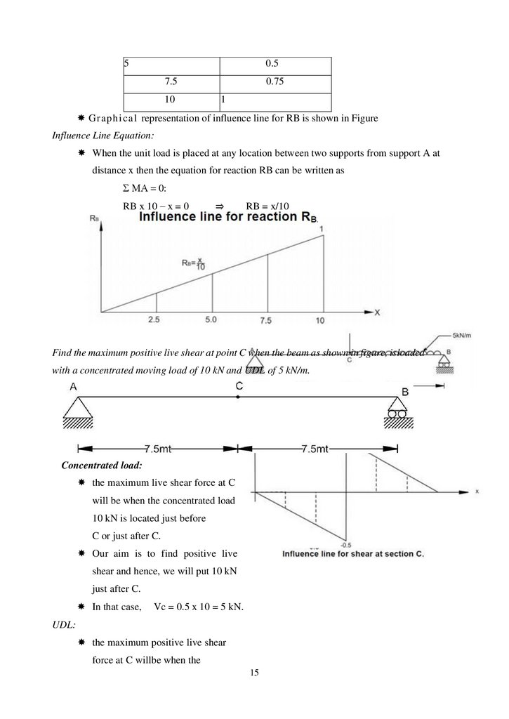
Graphi cal representation of influence line for RB is shown in Figure
Influence Line Equation:
When the unit load is placed at any location between two supports from support A at
distance x then the equation for reaction RB can be written as
Σ MA = 0:
RB x 10 – x = 0
⇒
RB = x/10
Find the maximum positive live shear at point C when the beam as shown in figure, isloaded
with a concentrated moving load of 10 kN and UDL of 5 kN/m.
Concentrated load:
the maximum live shear force at C
will be when the concentrated load
10 kN is located just before
C or just after C.
Our aim is to find positive live
shear and hence, we will put 10 kN
just after C.
In that case,
Vc = 0.5 x 10 = 5 kN.
UDL:
the maximum positive live shear
force at C willbe when the
15
23.
UDL 5 kN/m is acting betweenx = 7.5 and x = 15.
Vc
=
[ 0.5 x (15 –7.5) (0.5)] x 5
=
9.375
Total maximum Shear at C:
(Vc) max
=
5 + 9.375
=
14.375.
Overhang beam
Muller Breslau Principle for Qualitative Influence Lines
In 1886, Heinrich Müller Breslau proposed a technique to draw influence lines
quickly.
The Müller Breslau Principle states that the ordinate value of an influence line for any
function on any structure is proportional to the ordinates of the deflected shape that is
obtained by removing the restraint corresponding to the function from the structure and
introducing a force that causes a unit displacement in the positive direction.
Procedure:
First of all remove the support corresponding to the reaction and apply a force in the
positive direction that will cause a unit displacement in the direction of RA
Deflected shape of beam
The resulting deflected shape will be proportional to the true influence line for the
support reaction at A.
Influence line for support reaction A
The deflected shape due to a unit displacement at A is shown in above Figure:1 and
16
24.
matches with the actual influence line shape as shown in Figure 3.Note that the deflected shape is linear, i.e., the beam rotates as a rigid body without
any curvature. This is true only for statically determinate systems.
17
25.
Overhang beamDeflected shape of beam
Now apply a force in the positive direction that will cause a unit displacement in the
direction of VC.
The resultant deflected shape is shown above Figure. Again, note that the deflected
shape is linear.
Influence line for shear at section C
18
26.
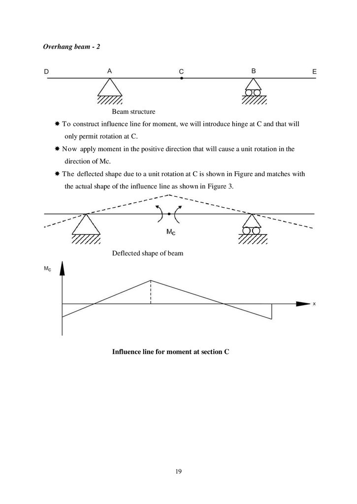
Overhang beam - 2Beam structure
To construct influence line for moment, we will introduce hinge at C and that will
only permit rotation at C.
Now apply moment in the positive direction that will cause a unit rotation in the
direction of Mc.
The deflected shape due to a unit rotation at C is shown in Figure and matches with
the actual shape of the influence line as shown in Figure 3.
Deflected shape of beam
Influence line for moment at section C
19
27.
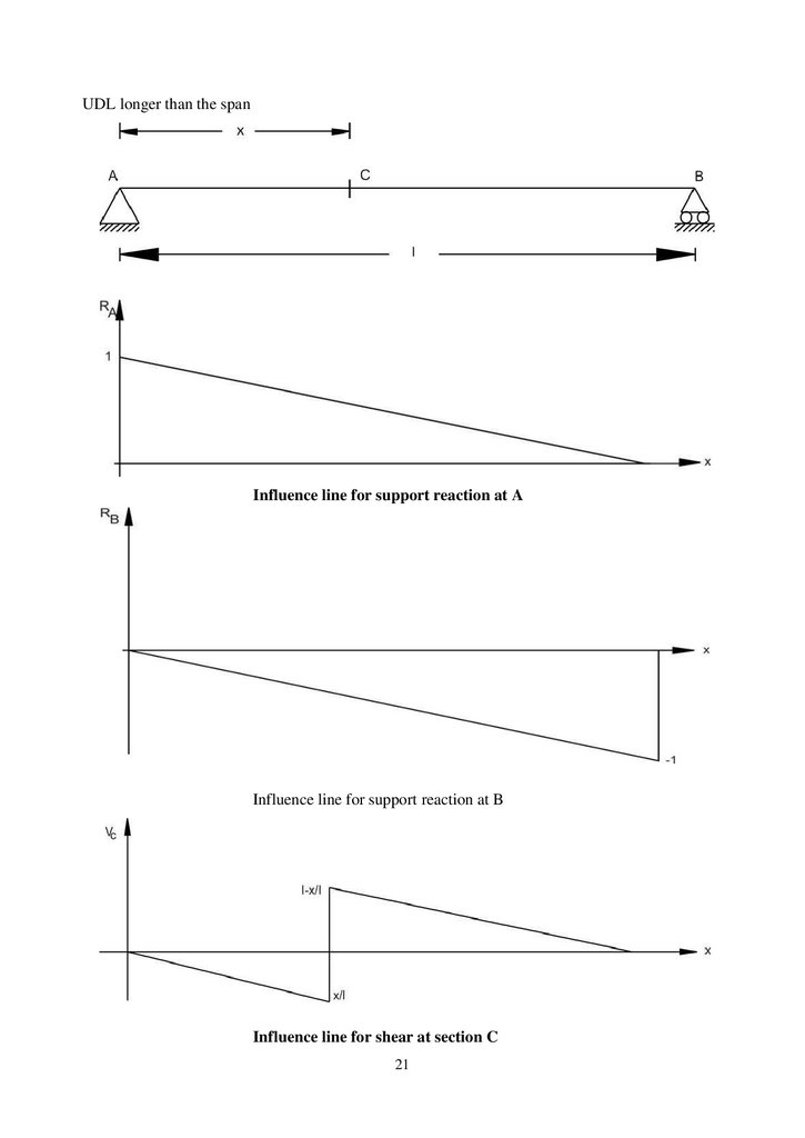
Maximum shear in beam supporting UDLsUDL longer than the span
Influence line for moment at section C
Suppose the section C is at mid span, then maximum moment is given by
20
28.
UDL longer than the spanInfluence line for support reaction at A
Influence line for support reaction at B
Influence line for shear at section C
21
29.
Maximum negative shear is given byMaximum positive shear is given by
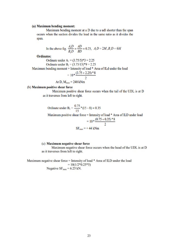
Problem : Draw the ILD for shear force and bending moment for a section at 5m from the left
hand support of a simply supported beam, 20m long. Hence, calculate the maximum bending
moment and shear force at the section, due to a uniformly distributed rolling load of length 8m
and intensity 10 kN/m run.
22
30.
2331.
1. Two point loads of 100 kN and 200 kN spaced 3m apart cross a girder of span 15m from left toright with the 100 kN load loading. Draw the influence line for shear force and bending moment
and find the value of maximum shear force and bending moment at a section, 6m from the left
hand support. Also, find the absolute maximum moment due to the given load system.
2. .A train of 5 wheel loads crosses a simply supported beam of span 22.5 m. Using influence
lines, calculate the maximum positive and negative shear forces at mid span and absolute
maximum bending moment anywhere in the span
3. A girder a span of 18mis simply supported at the ends. It is traversed by a train of loads as
shown in fig. The 50 kN load loading. Find the maximum bending moment which can occur (i)
under the 200 kN load (ii) Under 50 kN load, using influence line diagrams
24
32.
SCHOOL OF BUILDING AND ENVIRONMENTDEPARTMENT OF CIVIL ENGINEERING
UNIT –III – STRUCTURAL ANALYSIS II – SCI1307
33.
UNIT IIIFlexibility Matrix Method
INTRODUCTION
These are the two basic methods by which an indeterminate skeletal structure is analyzed.
In these methods flexibility and stiffness properties of members are employed. These methods
have been developed in conventional and matrix forms. Here conventional methods are discussed.
Suitable number of releases. The number of releases required is equal to statically
indeterminacys. Introduction of releases results in displacement discontinuities at these releases
under the externally applied loads. Pairs of unknown biactions (forces and moments) are applied
at these releases in order to restore the continuity or compatibility of structure.
The computation of these unknown biactions involves solution of? linear simultaneous
equations. The number of these equations is equal to staticalindeterminacy s. After the unknown
biactions are computed all the internal forces can be computed in the entires tructure using
equations of equilibrium and free bodies of members. The required displacements can also be
computed using methods of displacement computation.
Inflexibility methods in unknowns are forces at the releases the method is also called force
method. Since computation of displacement is also required at releases for imposing conditions of
compatibility the method is also called compatibility method. In computation of displacements use
is made of flexibility properties, hence, the method is also called flexibility method.
DETERMINATE AND INDETERMINATE STRUCTURAL SYSTEMS
If skeletal structure is subjected to gradually increasing loads, without distorting the initial
geometry of structure, that is, causing small displacements, the structure is said to be stable.
Dynamic loads and buckling or instability of structural system are not considered here. If for the
stable structure it is possible to find the internal forces in all the members constituting the
structure and supporting reactions at all the supports provided from statically equations of
equilibrium only, the structure is said to be determinate.
If it is possible to determine all the support reactions from equations of equilibrium alone
the structure is said to be externally determinate externally indeterminate. If structure is
34.
externally determinate but itis not possible to determine all internal forces then structure issaid tobe internally indeterminate. Therefore a structural system may be:
(1) Externally indeterminate but internally
determinate(2)Externally determinate but
internally indeterminate(3)Externally and
internally indeterminate (4)Externally and
internally determinate
DETERMINATEVs INDETERMINATESTRUCTURES.
Determinate structures can be solving using conditions of equilibrium alone (H=0; V=0
;M=0). No other conditions are required.
Indeterminate structures cannot be solved using conditions of equilibrium because
(?H=0; ?V=0;?M=0). Additional conditions are required for solving such structures. Usually
matrix methods are adopted.
Flexibility Matrix Method
A systematic development of consistent deformation method is also known as flexibility matrix
method or force matrix method. In this method, the basic unknowns to be determined are
redundant forces. Hence, the degree of static indeterminacy of the structure is calculated first and
then coordinate number is assigned to each redundant force direction. Thus, if F1, F2, …, Fn are
the redundant forces in the coordinate direction 1, 2, …, n respectively. If the restraints to the
entire redundant are removed, the resulting structure is called as basic determinate structure or
Released structure. From the principle of superposition, the net displacement at any point in a
statically determinate structure is the sum of the displacement in basic determinate structure due
to the applied loads and redundant forces.
The above equation can be expressed in matrix form as
where, DQ = Displacement corresponding to action in original structure
DQL = Displacement corresponding to action in released structure
F = Flexibility coefficient factor matrix
Q = Unknown redundant force matrix.
3
35.
In the indeterminate structure, the final displacements [Δ] are either zero or known values. Thesolution for [F] from above equation gives all the redundant forces. Then, bending moment, shear
forces at any required point can be calculated by using equations of statics.
Application
1 Analysis of pin jointed plane trusses
2. Analysis of continuous beams
3. Analysis of rigid jointed rectangular portal frame
Steps for the solution of Indeterminate Beams by Flexibility Method
1. Determine the degree of static indeterminacy (DI)
2. Choose the redundant
3. Assign the coordinates to the redundant force direction
4. Remove restraints to redundant forces and get basic determinate structure
5. Determine the deflections in coordinate directions due to given loading in the basic determinate
structure
6. Determine the flexibility matrix
7. Apply the compatibility conditions.
8. Calculate the redundant forces
9. Calculate member forces, shear forces and bending moment
10.Draw SFD, BMD
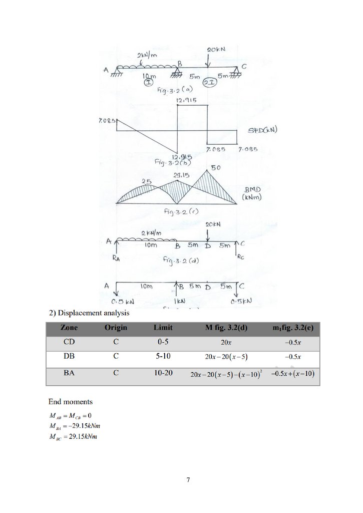
Problem : Analyse the continuous beam shown in fig by flexibility matrix method. Flexural
rigidity is constant throughout.
2) Displacement analysis
4
36.
Reaction calculationsHa=0
All vertical force equal to zero, then
5
37.
Problem : Analyse the continuous beam shown in figure 3.2(a) by flexibility matrix method.6
38.
739.
1. Differentiate between determinate and indeterminate structures.2. Define the term Degrees of freedom.
3. State the principle of superposition of forces.
4. Differentiate between determinate and indeterminate structures.
5. Define the term Degrees of freedom.
6. State the principle of superposition of forces.
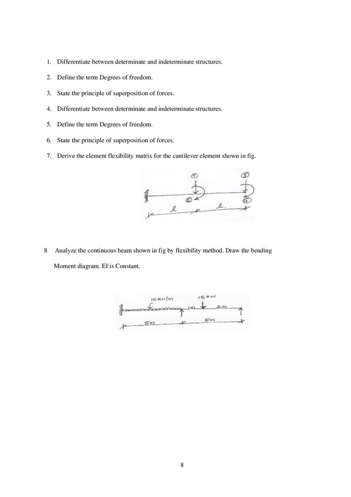
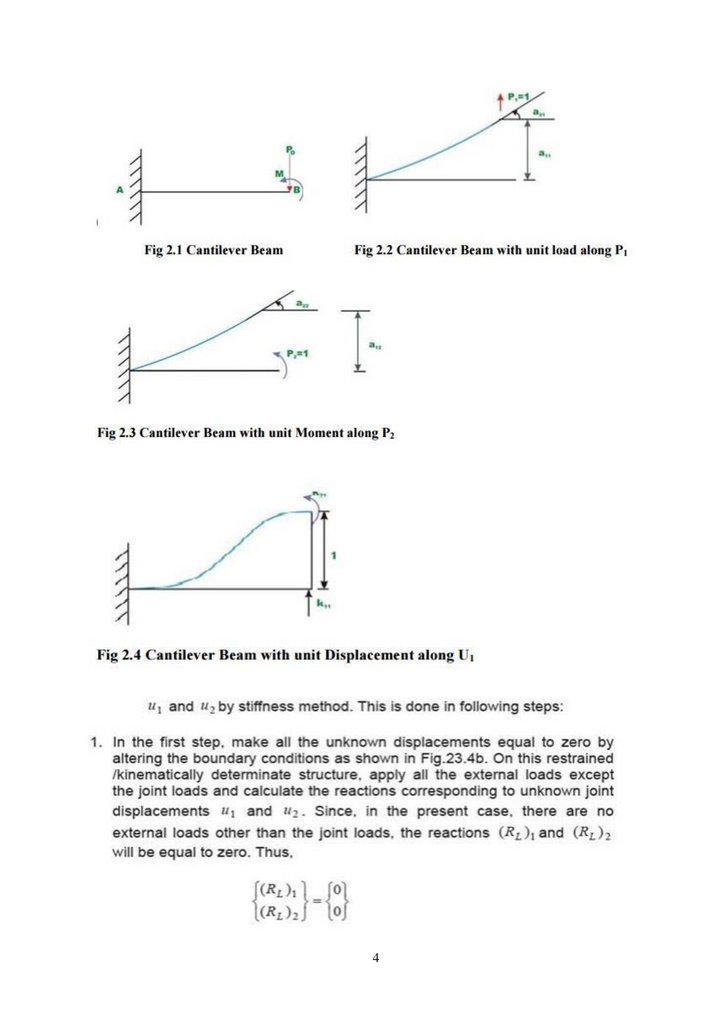
7. Derive the element flexibility matrix for the cantilever element shown in fig.
8
Analyze the continuous beam shown in fig by flexibility method. Draw the bending
Moment diagram. EI is Constant.
8
40.
SCHOOL OF BUILDING AND ENVIRONMENTDEPARTMENT OF CIVIL ENGINEERING
UNIT –IV – STRUCTURAL ANALYSIS II – SCI1307
41.
UNIT-IVSTIFFNESS MATRIX METHOD
INTRODUCTION
The given indeterminate structure is first made kinematic ally determinate by introducing
constraints at the nodes. The required number of constraints is equal to degrees of freedom at
the nodes that is kinematic indeterminacy. The kinematically determinate structure comprises of
fixed ended members, hence, all nodal displacements are zero. These results in stress resultant
discontinuities at these nodes under the action of applied loads or in other words the clamped
joints are not in equilibrium.
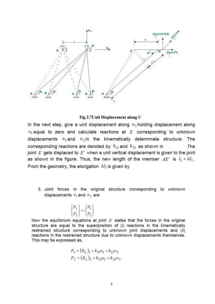
In order to restore the equilibrium of stress resultants at the nodes the nodes are imparted
suitable unknown displacements. The number of simultaneous equations represent ting joint
equilibrium of forces is equal to kinematic indeterminacy. Solution of these equations gives
unknown nodal displacements. Using stiffness properties of members, the member end forces
arecomputed and hence the internal forces throughout the structure.
Since nodal displacements are unknowns, the method is also called displacement method.
Since equilibrium conditions are applied at the joints the method is also called equilibrium
method. Since stiffness properties of members are used the method is also called stiffness method.
DETERMINATE AND INDETERMINATE STRUCTURAL SYSTEMS
If skeletal structure is subjected to gradually increasing loads, without distorting the initial
geometry of structure, that is, causing small displacements, the structure is said to be stable.
Dynamic loads and buckling or instability of structural system are not considered here. If for the
stable structure it is possible to find the internal forces in all the members constituting the
structure and supporting reactions at all the supports provided from statically equations of
equilibrium only, the structure is said to be determinate.
If it is possible to determine all the support reactions from equations of equilibrium alone
the structure is said to be externally determinate externally indeterminate. If structure is
42.
externally determinate but itis not possible to determine all internal forces then structure issaid tobe internally indeterminate. Therefore a structural system may be:
(1) Externally indeterminate but internally
determinate
(2) Externally determinate but internally
indeterminate
(3) Externally and internally indeterminate (4)
Externally and internally determinate
PROPERTIES OF THE STIFFNESS MATRIX
The properties of the stiffness matrix are:
It is asymmetric matrix
The sum of elements in any column must be equal to zero.
It is an unstable element therefore the determinant is equal to zero.
ELEMENT AND GLOBAL STIFFNESS MATRICES
Local co ordinates
In the analysis for convenience we fix the element coordinates coincident with the
memberaxis called element (or) local coordinates (coordinates defined along the individual
member axis )
Global co ordinates
It is normally necessary to define a coordinate system dealing with the entire structure is called
system on global coordinates (Common coordinate system dealing with the entire structure)
Transformation matrix
The connectivity matrix which relates the internal forces Q and the external forces R is known
as the force transformation matrix. Writing it in a matrix form,
{Q} =[b]{R}
Where Q=member force matrix/vector, b=force transformation matrix R = external force/load
matrix/ vector
ANALYSIS OF CONTINUOUS BEAMS
3
43.
444.
545.
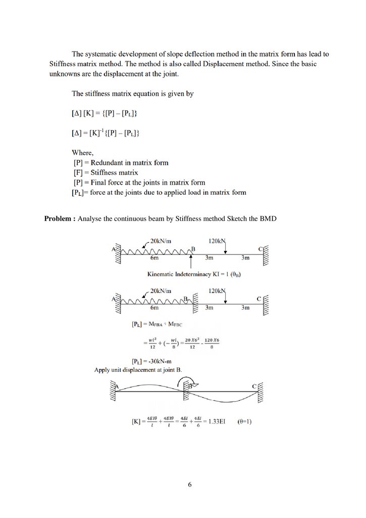
Problem : Analyse the continuous beam by Stiffness method Sketch the BMD6
46.
747.
Problem: Analyse the continuous beam by Stiffness method Sketch the BMD8
48.
949.
1. What is stiffness coefficient?2. Define kinematic indeterminacy.
3. What is axial stiffness?
4. In what way stiffness matrix differ from flexibility matrix
1. Using stiffness method draw bending moment diagram of the continuous beam ABCD (All
the supports are freely supported). Span AB (12 m) carried uniformly distributed load of
4kN/m Span BC (12 m) carried central concentrated load of 12 kN. Span CD (12 m) carried
uniformly distributed load of 2 kN/m.
2. Derive the element stiffness matrix for the cantilever element shown in fig. Assume uniform
EI
3. Set up stiffness matrix or stiffness influence coefficients for a beam element of uniform
flexural rigidity considering the following displacement.
4. Set up the element stiffness matrix for a beam element subjected to clockwise moments at the
two ends. Assume uniform EI.
5. Analyze the given continuous beam using displacement method? Draw BMD
10
50.
SCHOOL OF BUILDING AND ENVIRONMENTDEPARTMENT OF CIVIL ENGINEERING
UNIT –V – STRUCTURAL ANALYSIS II – SCI1307
51.
UNIT –VPLASTIC ANALYSIS OF STRUCTURES
1. Statically indeterminate axial problems
In these analyses we used superposition often, knowing that for a linearly elastic
structure it was valid. However, an elastic analysis does not give information about the
loads that will actually collapse a structure. An indeterminate structure may sustain loads
greater than the load that first causes a yield to occur at any point in the structure.
In fact, a structure will stand as long as it is able to find redundancies to yield. It is
only when a structure has exhausted all of its redundancies will extra load causes it to fail.
Plastic analysis is the method through which the actual failure load of a structure is
calculated, and as will be seen, this failure load can be significantly greater than the elastic
load capacity.
To summarize this, Prof. Seande Courcy (UCD) used to say: 'a structure only
collapses when it has exhausted all means of standing'.
Before analyzing complete structures, we review material and cross section behavior beyond
theelastic limit.
2. Beams in pure bending
2.1. Material Behavior
A uniaxial tensile stress on a ductile material such as mild steel typically provides the
followinggraph of stress versus strain:
52.
As can be seen, the material can sustain strains farinexcess of the strain at which yieldoccurs before failure. This property of the material is called its ductility. Though complex
models do exist to accurately reflect the above real behavior of the material, the most
common, and simplest, model is the idealized stress-strain curve. This is the curve for an
ideal elastic-plastic material (which doesn't exist), and the graph is:
As can be seen, once the yield has been reached it is taken that an indefinite amount
of strain can occur. Since so much post-yield strain is modeled, the actual material (or
cross section) must also be capable of allowing such strains. That is, it must be sufficiently
ductile for the idealized stress-strain curve to bevalid. Next we consider the behavior of
across section of an ideal elastic- plastic material subject to bending. In doing so, we seek
the relationship between applied moment and the rotation (or more accurately, the
curvature) of across section.
2.2. Moment-Rotation Characteristics of General Cross Section
We consider an arbitrary cross-section with a vertical plane of symmetry, which is also the
plane of loading. We consider the cross section subject to an increasing bending moment,
and assess thestresses at each stage.
53.
Stage1- Elastic BehaviourThe applied moment causes stresses over the cross-section that are all less than the yield stress of
the material.
Stage2-Yield Moment
The applied moment is just sufficient that the yield stress of the material is reached at the outer
most fibre(s) of the cross-section. All other stresses in the cross section are less than the yield
stress. This is limit of applicability of an elastic analysis and of elastic design. Since all fibres are
elastic, the ratio of the depth of the elastic to plastic regions,
Stage3- Elasto-Plastic Bending
The moment applied to the cross section has been increased beyond the yield moment. Since by
the idealized stress-strain curve the material cannot sustain a stress greater than yield stress, the
fibres at the yield stress have progressed inwards towards the centre of the beam. Thus over the
cross section the reisanelastic core and a plastic region. The ratio of the depth of the elastic core to
the plastic region is .
54.
Since extra moment is being applied and no stress is bigger than the yield stress, extra rotationof the section occurs: the moment-rotation curve losses its linearity and curves, giving more
rotation per unit moment (i.e. looses stiffness).
Stage4- Plastic Bending
The applied moment to the cross section is such that all fibres in the cross section are at yield
stress. This is termed the Plastic Moment Capacity of the section since there are no fibres at an
elastic stress, Also note that the full plastic moment requires an infinite strain at the neutral axis
And so is physically impossible to achieve. However, it is closely approximated in practice. Any
attempt at increasing the moment at this points imply results in more rotation, once the crosssection has sufficient ductility. There fore in steel members the cross section classification must
be plastic and in concrete members the section must be under-reinforced.
Stage5-Strain Hardening
Due to strain hardening of the material, a small amount of extra moment can be sustained.
The above moment-rotation curve represents the behavior of across section of a regular elasticplastic material. However, it is usually further simplified as follows:
With this idealized moment-rotation curve, the cross section linearly sustains moment up to the
plastic moment capacity of the section and then yields in rotation an indeterminate amount. Again,
to use this idealization, the actual section must be capable of sustaining large rotations- that is it
must be ductile.
Analysis of Rectangular Cross Section
Since we now know that across section can sustain more load than just the yield moment, we are
interested in how much more. In other words we want to find the yield moment and plastic
moment, and we do so for a rectangular section. Taking the stress diagrams from those of the
moment-rotation curve examined previously, we have:
55.
3. Shape FactorThus the ratio of elastic to plastic moment capacity is:
This ratio is termed the shape factor,f, and is a property of across section alone. For a rectangular
cross-section, we have:
And so a rectangular section can sustain 50% more moment than the yield moment, before a plastic
hinge is formed. Therefore the shape factor is a good measure of the efficiency of across section
In bending. Shape factors for some other cross sections are
4. Plastic Hinge
Note that once the plastic moment capacity is reached, the section can rotate freely- that is,
it behaves like a hinge, except with moment of M patthe hinge. This is termed a plastic hinge, and
is the basis for plastic analysis. At the plastic hinge stresses remain constant, but strains and hence
rotations can increase.
56.
4.1. Methods of Plastic Analysis1. The Incremental Method
This is probably the most obvious approach: the loads on the structure are incremented until
the first plastic hinge forms. This continues until sufficient hinges have formed to collapse the
structure. This is a labour-intensive, 'brute-force', approach, but one that is most readily suited for
computer implementation.
2. The Equilibrium (or Statical) Method
In this method, free and reactant bending moment diagrams are drawn. These diagrams are
over laid to identify the likely locations of plastic hinges. This method therefore satisfies the
equilibrium criterion first leaving the two remaining criterion to derived therefrom.
3. The Kinematic (or Mechanism) Method
In this method, a collapse mechanism is first postulated. Virtual work equations are then
written for this collapse state, allowing the calculations of the collapse bending moment diagram.
This method satisfies the mechanism condition first, leaving the remaining two criteria to be
derived there from.
We will concentrate mainly on the Kinematic Method, but introduce now the Incremental
Method to illustrate the main concepts.
4.1.1. Incremental Method
Example1- Propped Cantilever
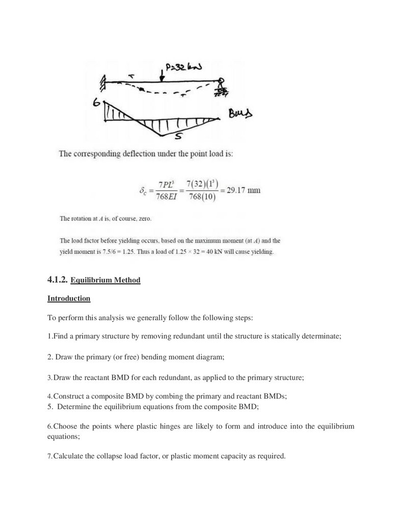
We now assess the behavior of a simple statically indeterminate structure under increasing load.
We consider a propped cantilever with mid-span point load:
57.
Since the peak moments are less than the yield moments, we know that yield stress has not beenreached at any point in the beam. Also, the maximum moment occurs at A and so this point will
first reach the yield moment.
58.
4.1.2. Equilibrium MethodIntroduction
To perform this analysis we generally follow the following steps:
1.Find a primary structure by removing redundant until the structure is statically determinate;
2. Draw the primary (or free) bending moment diagram;
3. Draw the reactant BMD for each redundant, as applied to the primary structure;
4. Construct a composite BMD by combing the primary and reactant BMDs;
5. Determine the equilibrium equations from the composite BMD;
6. Choose the points where plastic hinges are likely to form and introduce into the equilibrium
equations;
7. Calculate the collapse load factor, or plastic moment capacity as required.
59.
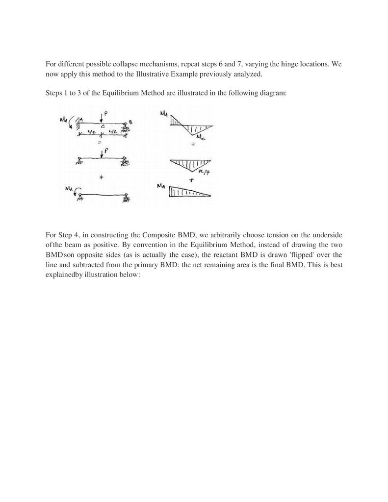
For different possible collapse mechanisms, repeat steps 6 and 7, varying the hinge locations. Wenow apply this method to the Illustrative Example previously analyzed.
Steps 1 to 3 of the Equilibrium Method are illustrated in the following diagram:
For Step 4, in constructing the Composite BMD, we arbitrarily choose tension on the underside
of the beam as positive. By convention in the Equilibrium Method, instead of drawing the two
BMD son opposite sides (as is actually the case), the reactant BMD is drawn 'flipped' over the
line and subtracted from the primary BMD: the net remaining area is the final BMD. This is best
explainedby illustration below:
60.
61.
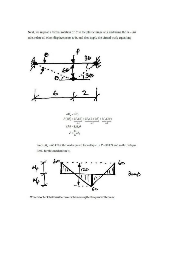
Kinematic Method Using Virtual Work IntroductionProbably the easiest way to carry out a plastic analysis is through the Kinematic Method using
virtual work. To do this we allow the presumed shape at collapse to be the compatible displace
mentset, and the external loading and internal bending moments to be the equilibrium set. We can
62.
then equate external and internal virtual work, and solve for the collapse load factor for thatsupposed mechanism.
Remember:
Equilibrium set: the internal bending moments at collapse;
Compatibleset: the virtual collapsed configuration (see below).
Note that in the actual collapse configuration the members will have elastic deformation in
between the plastic hinges. However, since a virtual displacement does not have to be real, only
compatible, we will choose to ignore the elastic deformations between plastic hinges, and take the
members to be straight between them.
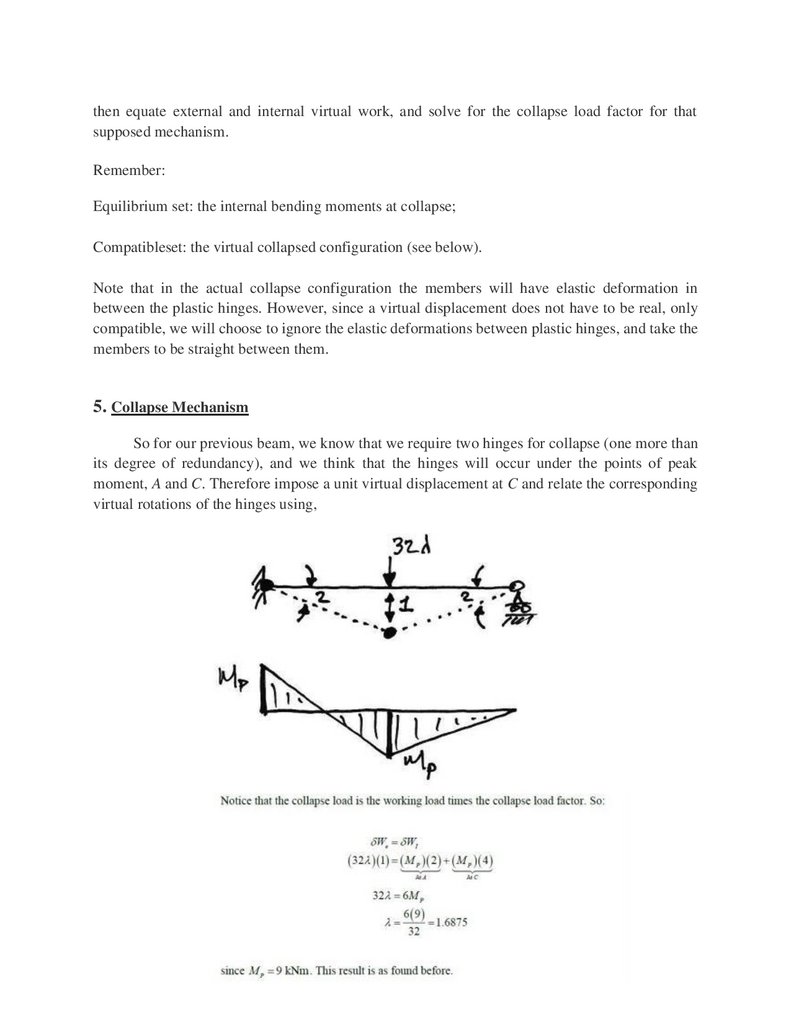
5. Collapse Mechanism
So for our previous beam, we know that we require two hinges for collapse (one more than
its degree of redundancy), and we think that the hinges will occur under the points of peak
moment, A and C. Therefore impose a unit virtual displacement at C and relate the corresponding
virtual rotations of the hinges using,
63.
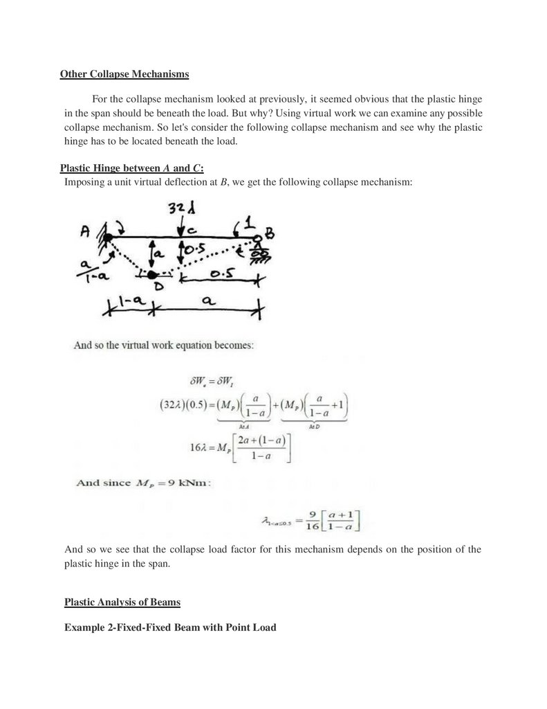
Other Collapse MechanismsFor the collapse mechanism looked at previously, it seemed obvious that the plastic hinge
in the span should be beneath the load. But why? Using virtual work we can examine any possible
collapse mechanism. So let's consider the following collapse mechanism and see why the plastic
hinge has to be located beneath the load.
Plastic Hinge between A and C:
Imposing a unit virtual deflection at B, we get the following collapse mechanism:
And so we see that the collapse load factor for this mechanism depends on the position of the
plastic hinge in the span.
Plastic Analysis of Beams
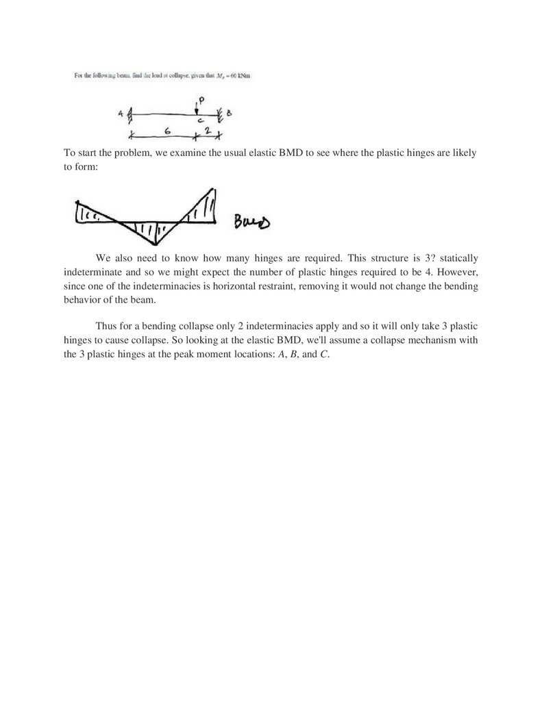
Example 2-Fixed-Fixed Beam with Point Load
64.
To start the problem, we examine the usual elastic BMD to see where the plastic hinges are likelyto form:
We also need to know how many hinges are required. This structure is 3? statically
indeterminate and so we might expect the number of plastic hinges required to be 4. However,
since one of the indeterminacies is horizontal restraint, removing it would not change the bending
behavior of the beam.
Thus for a bending collapse only 2 indeterminacies apply and so it will only take 3 plastic
hinges to cause collapse. So looking at the elastic BMD, we'll assume a collapse mechanism with
the 3 plastic hinges at the peak moment locations: A, B, and C.
65.
66.
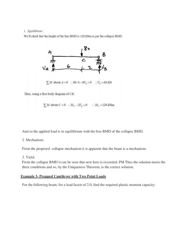
And so the applied load is in equilibrium with the free BMD of the collapse BMD.2. Mechanism:
From the proposed collapse mechanism it is apparent that the beam is a mechanism.
3. Yield:
From the collapse BMD it can be seen that now here is exceeded. PM Thus the solution meets the
three conditions and so, by the Uniqueness Theorem, is the correct solution.
Example 3- Propped Cantilever with Two Point Loads
For the following beam, for a load factor of 2.0, find the required plastic moment capacity:
67.
Once again we try to picture possible failure mechanisms. Since maximum moments occurunderneath point loads, there are two real possibilities:
68.
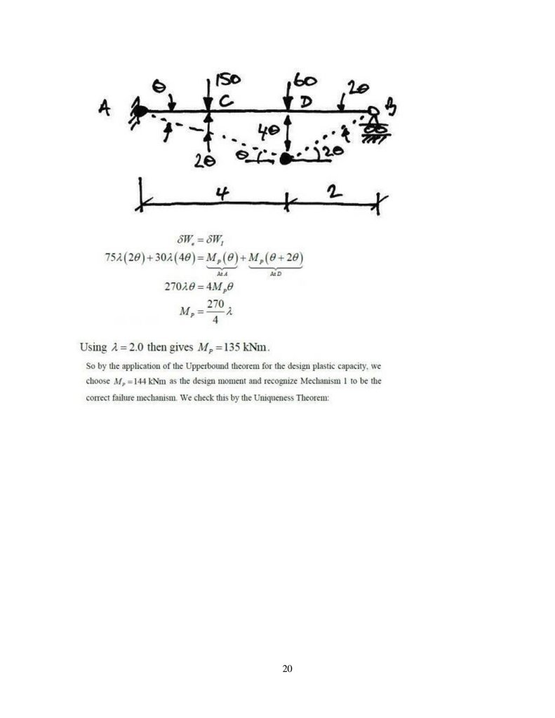
Therefore, we analyse both and apply the Upper bound Theorem to find the design plastic momentcapacity.
Mechanism1: Plastic Hingeat C:
69.
2070.
1. Draw the stress-strain diagram for mild steel.2. List the assumptions in plastic theory.
3. Define load factor.
4. sketch an idealized stress strain relation for structural steel.
5. Define the term “Shape factor”.
6. Define: Plastic moment.
7. Determine the collapse load for a propped cantilever with UDL.
8. A beam ABC of span “L” is fixed at ends A&C and carries a point load at a distance L/4 from
the left end. Find the value of the load at collapse if the left half of the beam has 2Mp and the
right half has 1Mp.
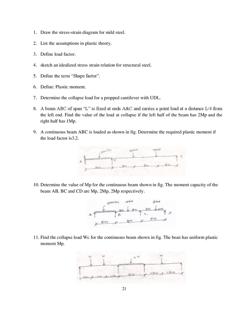
9. A continuous beam ABC is loaded as shown in fig. Determine the required plastic moment if
the load factor is3.2.
10. Determine the value of Mp for the continuous beam shown in fig. The moment capacity of the
beam AB, BC and CD are Mp, 2Mp, 2Mp respectively.
11. Find the collapse load Wc for the continuous beam shown in fig. The bean has uniform plastic
moment Mp.
21