


 electronics
Similar presentations:


西安西 立 电子 员工 培训. Cutting Plotter
1.
西安西立电子员工培训2.
Cutting Plotter3.
4.
Helitin Bell Tech21 CO.,LTD is a Sino-Japan Joint Venture thatspecializes in research and development, production and sales of
advertising equipment and components in Xi’an, China, with many
patents, our machines was sold to 50 countries of the whole world.
Especially auto cutting plotter is one of our high technology
products, which is very convenient and attractive to most customers.
In order to make the most customers use machines conveniently,
hereby write this training courses.
5.
Cutting plotter Trarining Directory§Overall Structure Training
§Overwall Installation Training
§Software Installation Training
§Software Content Traning
§Overall Maintenance Training
6.
§Overall Structure TraningIn order to make users know more about machine fully, now we make a brief introduction about spare parts.
7.
8.
§Overall Installation Training★Brackets Mounting
1.As shown pic 1, connected 2pcs flat feet components and 2pcs vertical feet components by screws of 8M5*15.
2. As shown pic 2, connected beam components and left& right vertical feet by 8-M4*20 of screws, flat gasket, flexible
spring washer.
3.Connected left&right brackerts , flat gasket, flexible spring washer with 2pcs vertical feet by
Screw of 8-M4*20.
图1
图2
图3
机腿长侧在
后
9.
4.Regarding pics 4, put rolling media bar into groove of left & right holder, rotatingFlexible.
5. Mounted frame as shown pic 5
6.As shown pic, connected frame components and machine head components by screw
Of 4-M6*15, flat gasket and flexible gasket firmly.
图4
图5
图6
10.
★Installing media1.Before installing media,, put pinch roller on the feeding roller as shown pic 1, if media cannot cover pinch roller, you can
put it on the shaft (avoiding grit roller touched with feeding roller directly, friction will damages grit roller)
2.Put media on the media loading lever as shown pic 2.
3. When putting paper, pls keep the paper in straight line on forward and back
11.
★Installation & adjustment of blade holder1.As shown pic 1 structure of blade, it consists of adjusting lever, adjusting bolt, clamping screw and blade ect. Rotating
the adjusting bolt to control the extended length of blade. Make sure that blade can not cut bottom layer of sticker. (Sticker
consists of two layers).
2.Before installing, pls keep blade holder and blade clean , because tiny dust will affect on blade’s flexibility.
Step 1: Take tail of blade penetrate into the hole of blade
holder.
Step 2: Adjust the bolts to control the extended length
of blade to be suitable position, then tighten clamping
screw.
Step
3: When taking out of blade, pressing down
adjusting lever and taking of blade.
12.
3.Installing blade holder
As photos shown below: Load the blade holder with installed blade into support of carriage, and then tighten the
left clamping knob to fix firmly the blade holder on the carriage of machine. After finished, test blade pressure and
length of blade, power on machine and press the “TEST” button, blade will cut a square, tear down it and check the
point of blade and pressure.
13.
★Introduction For Button& Main interface14.
Common cutting plotter operation& Artcut software installation1. Insert the CD of Artcut software into computer CD-ROM device. Image 1;
2. Click the button of next step referring to image 2, and then choose “Yes” as per image 3;
3. Select the installation directory properly
图2
图1
图4
图3
4.Choose the button “next step”
5.After finishing the program installation, click the button”finish”
图5
图6
图7
图8
15.
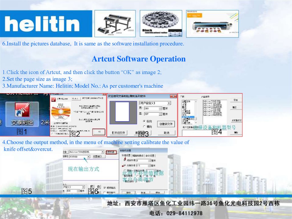
6.Install the pictures database, It is same as the software installation procedure.Artcut Software Operation
1.Click the icon of Artcut, and then click the button “OK” as image 2;
2.Set the page size as image 3;
3.Manufacturer Name: Helitin; Model No.: As per customer's machine
图1
图2
图3
4.Choose the output method, in the menu of machine setting calibrate the value of
knife offset&overcut.
图5
图6
图4
16.
5.COM port setting; Click to connect with COM port, choose the baud rate 34.8K in the submenu of port setting.Inspecial case, keep the same tranfer rate between cutter and software.Press the enter to finish the setting.
图9
图7
图8
6.Choose the USB output. According to the computer bit,install USB driver correctly.For example,our computer is 32 bit,
we choose to install the drive as image 11.Click the button in image 12 to finish installation successfully
图13
图10
图11
图12
17.
7.Finish the design jobs in software as image 14 and then output the fileby clicking the button of image 15.Before cutting, choose the correct
output port as image 16.
图14
图15
图16
18.
CorelDRAW Sofware Traning★Software Installation
This CCD camera machine uses CorelDRAW software, we make plugin for it. When users use plugin, pls
install CorelDRAW software. After finishing installed, we will install plugin. Now we mainly introduce method how to
install plugin.
Before installing, pls check your computer’s bit (32bit or 64bit), Press right button and find “my computer”,
also find“Property”Pic1, pic2.
1.
In the CD of cutting plotter, pls find plugin by pic 3 and uncompress the folder
2.
Open the uncompressed folder, click it & install plugin by pic 4 .
图1
图2
图3
图4
19.
3. Click “Next step” as shown pic 5.4. Select the location where the software is intalled, click“Next step”.
5. Select plugins that are consistent with your software version-pic 7.
6. Click “finish”- pic 8.
图5
图6
图7
图8
20.
★Software Operation1. Pls insert USB dongle on the USB port of computer as shown pic 1.
2. Open software as shown pic 2.
3. Select “Import”from software’s menu bar as shown pic 3, and import pic into software—pic 4.
4. Select plugins which will be installed from the application programme (pic 5), open plugin.
图1
图2
图3
图4
图5
21.
5. Select a pic, click “Extract contour”(pic 6), as shown pic 7 it’s the distance between pic and contour outline. After finished,click “Extract contour” as shown pic 7.
图6
图7
图8
图9
6. After created outline, then add Mark point(pic 8).As shown pic 9, it’s the distance between pic and mark point. After
finished, click “confirm”. After finished pic outline and mark point, from software export pic (pic 10). Export format you can
choose according to your printer, But when printing & output, the pic must be 1:1, do not make any adjustment, if so, the
cutting is not consistent with original pic.
图10
22.
7.Save the finished photo (Pic 11).图11
★Machine Oerpration
1. Put the printed photos on machine, power on machines, and press “OFFLINE” button. Press UP/DOWN/LEFT/RIGHT
buttons and move carriage, let blade holder move to 1 st mark point of photo as shown pic 1 and 2. And ajust the interface of
speed and force from screen (pic 3). <if it’s servo mainboard , light is dim, you can adjust the interface to be “LASERACT”,
then camera LED will be on.>
Speed:
Force:
图1
图3
图2
500
140
图4
23.
2.Open the saved original file from computer, also open plugin and choose “outline output”(pic 1), choose the outputroute and 2 offset value.(according to customers’ media to choose), at last click “send”, then machine will start to contour
working.
3. When cutting results had small deviation, you can adjust outline offset by UP/DOWN/LEFT/RIGHT buttons as shown
pic 7 (servo mainboard) , when stepper mainboard, entry the interface of pic 8 (Camera SET), press “confirm” and entry
interface of pic 9, adjusting outline offset.
图5
图6
图9
图7
图8
24.
Automatic Contour Cutting Plotter★Software installation
1.Insert Software CD-ROM into computer, and open the installation program. (pic 1).
2. Select language and click “confirm” (pic 2).
3. Click “ I accept” and select “ Next Step”.
图1
图2
图3
图4
4. Select installation directory.
5. Select “Next Step”, installation program will start to load (pic 7)
图5
图6
图7
25.
7.When Program is loading, it will show you interface as shown pic 8. You need to pull USB dongle from computer andclick “confirm”, it will continue to load.
8. As shown pic 9 pls input password in software box, after input password, it will show code of USB dongle, it must be
consistent with USB dongle code of CD-RAM, then select language and click “finish”.
图8
9.After finished installing, the desktop will show you installed software.
26.
★Software Operation1.Open software pic 1, it will show you pic 2.
2. Open the software printmanager (pic3), pls set machine, select “Helitin” “Model type”, according to machine model, select
“R-1350-AML, R-720-AML, R-500-AML”.
图2
图1
图3
图4
3.Output method selects COM1&USB PORT OUTPUT , USB output select USB-Print- Select “finish”.
图5
27.
4.From software (menu bar) select “import” photo, adjust photo size from “Design Center”, then select the photo.5. From “Effect” selects “Contour Cut”, photo create outline, you can adjust distance between outline and photo in “Design
Center”, then click green color “√ “ (pic 9)
图6
图7
图8
图9
6.After outline finished, select outline cut mark from “Effect” (pic 10), in “Design Center” select SA automatic mark pic 11.
图10
图11
图12
28.
7.For finished photo select output format in “file options” and print out, the format to choose according to customers’ printermachines, saved photo must be same as printing photo 1:1.
8. Save own format when you make photo in FLEXI, will as an output file.
格式 作为输出文件。
8.把Flexi做好的图保存为自身的
29.
★Machine Operation1.Put the printed photo on machine, must put the blade on the 1 st mark point at 45 degree (pic 1).
图1
2.Open the output file, and click cut contour(pic 2), click “send”, the interface will show you “dialog box”(pic 4), servo
machine can click “confirm” directly, stepper machine when machine finish “contouring” and click “confirm”. Machine will
start to contour, if cutting outline had small deviation, you can adjust from pic 4.
图2
图3
图4
图5
30.
Cutting Plotter MaintenanceIn order to ensure good cutting effect, we should maintain the cutting plotter at a certain time.
Power off machine before maintenance.
A. Frequently clean the machine body by soft&dry cloth;
B. Use brush to clean the grit feed rollers &smear the anti-rust oil;
C. Make the surface of pinch rollers clean.
D. Separate the pinch rollers from grit feed roller Pinch Roller always keep upward
position)
31.
FAQ1. Cutting Abnormal
If this problem occur, there are several factors need to check : Setting of cutting software keeps same with machines, like
baud rate, port; Besides if during transferring , software shut down suddenly; The computer which is connectted to cutting
plotter have virus; Data cable problems.
2. Feeding paper with deviation
When putting paper, position is wrong. Lower pressure between pinch roller and feeding roller will has this problem; quality
of paper is not good, uneven thickness, holes, twist and distortion also will affect deviation; pinch roller or feeding rollers
have scraps of paper or other things.
3. When cutting, feeding paper is not smooth.
Length of blade is too longer, too much pressure, blade holder with dust, soft paper or too smooth paper all will lead to this
issues.
4. During operating getting lost content of cutting
Sticker wrapped too tight, cutting faster, too much pressures, leading to get lost content of cutting easily.
5. Words cutted has wrinkling problem .
Cutting faster or damaged blade, always check blade and use high quality blade; blade holder with dust also has this issues.
32.
6. Letter’s corner from cutting is not complete, the corner has provoking phenomenon.point of blade is longer, blade rotation is not flexible , pls change blade holder and adjust overcut and knife offset.
7. Different cutting route for same cutting content . If blade holder installed loose, it will lead to this problem.
8. When cutting smaller size letters, pls adjust speed and pressures to be minimum, meanwhile adjust the point of blade to be
shortest.