


")


")


 industry
Similar presentations:


Ball Charge Design and Management
1. Ball Charge Design and Management
2.
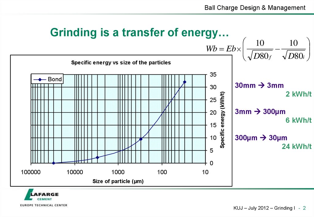
Ball Charge Design & ManagementGrinding is a transfer of energy…
Specific energy vs size of the particles
10
10
Wb Eb
D80i
D80 f
35
Bond
30mm 3mm
25
20
15
10
5
Specific energy (kWh/t)
30
2 kWh/t
3mm 300µm
6 kWh/t
300µm 30µm
24 kWh/t
0
100000
10000
1000
100
10
Size of particle (µm )
KUJ – July 2012 – Grinding I - 2
3.
Mill exitgas&+Management
dust
Ball Charge
Design
… from a mill to particles…
(mill motors = 85% of the power absorbed in the shop)
Mill rotation
Partition wall
Fresh feed +
Rejects
Material
Balls
Venti-
Balls
lation
Compartments
Liners C2
Liners C1
KUJ – July 2012 – Grinding I - 3
4. … throught the movement of balls…
Ball Charge Design & Management… throught the movement of balls…
P M b Q
Assumptions: lever b is proportional to Di
lever b is independent from mill speed
b x Di
P x Di Q x Di Q
n
30
simplified to
P c Di Q n[kW ]
c
with
x
30
Power Factors
0,270
1st. chamber
2nd. chamber
Power Factor [-]
0,250
c = power factor [-]
0,230
Q = Mass of ball charge [t]
0,210
0,190
Di= usefull diameter [m]
0,170
n = speed of mill shell [rpm]
0,150
18
20
22
24
26
28
30
32
34
36
38
40
42
Filling Degree [%]
KUJ – July 2012 – Grinding I - 4
5. … with a poor efficiency (95% lost in heat)
Ball Charge Design & Management… with a poor efficiency (95% lost in heat)
Specific energy vs size of the particles
35
Bond
25
20
Crushing (C1)
10 -12kWh/t
1/3 of mill
15
10
5
0
100000
10000
1000
100
10
Specific energy (kWh/t)
30
Attrition (C2)
~20kWh/t
2/3 of mill
50mm ~ 0,5mm
Crushing is more
efficient
Under ~0,5mm 5µm
Grinding by attrition
Rule
Max 5% residues at
mesh 2,5mm at the
end of C1
Size of particle (µm )
KUJ – July 2012 – Grinding I - 5
6. Matching Ball Sizes…
Ball Charge Design & ManagementOptimum Ball Diameter (mm)
Matching Ball Sizes…
Grinding Ball vs Clinker Size
100
10
.1
1
10
100
Clinker Size d80 (mm)
KUJ – July 2012 – Grinding I - 6
7. … without forgetting the effect of the liners
Ball Charge Design & Management… without forgetting the effect of the liners
KUJ – July 2012 – Grinding I - 7
8. Porosity
Ball Charge Design & ManagementPorosity
Coarse balls - large voids low retention
• Average ball weight
Fine balls - small voids
high retention
• total charge weight / total number of balls
• kg/ball
• Specific surface area
• total surface area / charge weight
• m2/ton
KUJ – July 2012 – Grinding I - 8
9. Volume loading
Ball Charge Design & ManagementVolume loading
Ball movement according filling degree / critical speed
Mill revolution - % of critical speed
Ball charge - % of mill volume
20%
40%
60%
70%
80%
90%
10%
20%
30%
40%
Area of best
grinding effect
KUJ – July 2012 – Grinding I - 9
10. Ball volume loading
Ball Charge Design & ManagementBall volume loading
Volume Load vs Specific Power (on circ. mass)
Specific Grinding Energy
(kWh/t mill throughput)
25
20
VL = approx. 25%
• Minimum
Grinding
Energy
(kWh/t)
15
10
5
15
20
25
30
35
Volume Load (%)
KUJ – July 2012 – Grinding I - 10
11. Following filling degree
Ball Charge Design & ManagementFollowing filling degree
F
A
di
S
100 %
A
The required surface area [S]
can be calculated by:
d h
S i
3 (di h )2 4 l 2 m²
6 l
The string value [l] can be calculated by:
S
h´
l
A = Free surface
S = Surface area of charge
d i d i h
l 8 di h
m
2
2
The filling degree can be calculated by measuring the free height
[h’] and the clear inside diameter [di] only.
KUJ – July 2012 – Grinding I - 11
12. Calculation of filling degree
Ball Charge Design & ManagementCalculation of filling degree
Filling degree f as a function of free
height h´ above ball charge
h´/di
0,75
0,70
0,65
0,60
20
25
30
35
f [%]
KUJ – July 2012 – Grinding I - 12
13. Chamber length / Ball charge
Ball Charge Design & ManagementChamber length / Ball charge
Length to diameter ratio (for OPC):
L
3,0 3,5 (closed circuit)
D
27 - 35%
L
3,5 5,0 (open circuit)
D
65 - 73%
M
2nd. Chamber
1st. Chamber
28 – 32%
volume load
30 – 32%
volume load
20 – 24 kWh/t
specific power
8 – 12 kWh/t
specific power
28 – 34 m²/t
specific surface
10 – 12 m²/t
specific surface
50 - 60g/ball
cement mill
1,6 – 1,8 kg/ball
cement mill
150 - 200g/ball
raw mil
1,5 – 2,0 kg/ball
raw mil
4,70 t/m³
bulk density
4,55 t/m³
bulk density
KUJ – July 2012 – Grinding I - 13
14. Ball Charge Fundamentals
Ball Charge Design & ManagementBall Charge Fundamentals
• In a ball mill, the balls grind the material
• Match the charge to the material particle size
• The ball charge has a major effect on material
progression in the tube
• Adjust the mill charge porosity or permeability, to the
amount of circulating load and throughput required
• Adjust the level of charge, or volume loading, to
optimize production and efficiency.
KUJ – July 2012 – Grinding I - 14
15. How to design a ball charge and manage it?
Calculation of a theoretical ball charge(always involve your Technical centre)
Optimisation of a ball charge in an existing mill
(better to involve Technical centre)
Ball charge management and follow-up
16. Theoretical ball charge
Ball Charge Design & ManagementTheoretical ball charge
• Parameters
• Product: type, composition, fineness, throughput…
• the ball charge design must produce the maximum output of
different types of optimum quality cement. The charge should be
adjusted to the type most produced.
• Material characteristics: crushability, grindability, size,
moisture…
• Mill: L/D, power available, internals, speed, ventilation…
• Whenever possible, the design should try to minimise the risk of
metal to metal contact and thereby the wear rate of components
Always take into account possible variations of these parameters
KUJ – July 2012 – Grinding I - 16
17. Design methodology
Ball Charge Design & ManagementDesign methodology
• Numerous attempts to make the process more scientific and
rigorous
• Slegten, Polysius Models
• Lafarge Corp. Mill Grinding Reference
• Effort continues with Best Practices
• Efforts are hampered by lack of
• Raw material testing data
• Crushability, feed size
• Consideration for mill & circuit design/condition
• Liner type & condition, mill sweep, separator type
• Lack of extensive trial & validation programme
… but methods can be a useful guide!
KUJ – July 2012 – Grinding I - 17
18. Design methodology
Ball Charge Design & ManagementDesign methodology
Definition of the volume
loading
Calculation of the tonnage
in each chamber
Calculation of the largest
ball size
Apply model
Chambers internal dimensions
Ball charge bulk density
BOND formula
Granulometry of the feed
material (D80)
Slegten or Polysius
KUJ – July 2012 – Grinding I - 18
19. Ball volume loading
Ball Charge Design & ManagementBall volume loading
1st compartment
2nd compartment
Minimum kWh/t
26 – 28%
28 – 30%
Maximum
Production
32 – 34%
34 – 36%
• The recommended volume loading for minimum kWh/t is based on an acceptable
compromise with production and by the amount of wear on the balls and liners
• The upper limits are the maximum absorbed power allowed by the drive, the
maximum level of the grinding charge with respect to the trunnions and to the central
partition vent opening
Experience indicates that the best volume loading for cement mills is
C1: 30 to 32%
C2: 28 to 32%
KUJ – July 2012 – Grinding I - 19
20. Biggest ball
Ball Charge Design & ManagementBiggest ball
Bond Formula
Ømax = 20,17 .
D20
K
3
Wi.
%Vc. Du
where,
Ømax
D20
K
Wi
Du
%Vc
= biggest ball diameter, mm
= sieve dimension where 20% is retained, µm
= constant (350 for dry mills, open or closed circuit , 300 for wet)
= specific mass of material, g / cm3
= Bond Work Index, kWh / t
= useful inside mill diameter, m
= % of critical speed
KUJ – July 2012 – Grinding I - 20
21. Ball charge design - C1
Ball Charge Design & ManagementBall charge design - C1
• Emphasis on crushing and less on grinding
• Typical top size
• 80 mm Ø if easy to crush, small feed size
• 90 mm Ø is the most common
• 100 mm Ø in rare cases: very hard, coarse feed
• Coarser ball charges give good crushing capability but
• Too porous - shorter retention
• Less surface, less grinding
• Can result in poor preparation for second chamber if you
overfeed (usually forced to underfeed)
• Extra wear
KUJ – July 2012 – Grinding I - 21
22. Ball charge design - C2
Ball Charge Design & ManagementBall charge design - C2
• Emphasis on attrition grinding
• Cement grinding wants maximum fines generation (Blaine)
• Top size depends on how much preparation is done in the first
chamber. Recommendation : 30 ... 50 mm
• Smallest size depends on the discharge grate slot size
• Practical rule of thumb: smallest Ø = 2 X slot width
• E.g. slot width = 8-10 mm: smallest Ø = 16-20 mm
• Non-classifying liners limits C2 to 3 sizes (or size ratio 2:1)
Classifying liners allow a large variety of Ø’s
• Best Practice “Ball Charge Level Management”
KUJ – July 2012 – Grinding I - 22
23. Effective length curves
Ball Charge Design & ManagementEffective length curves
• Convert the % weight to equivalent % length
• Plot effective mill length vs. ball Ø
• Connect midpoints
Alpena FM19 (1989) - Effective Length Curve
Partition
Ball Diameter, inches
4
3
Effective Length Curve
2
Cumulative Length Plot
1
0
0
2
4
6
8
10
12
Length, m (from Feed End)
KUJ – July 2012 – Grinding I - 23
24. Why use a curve?
Ball Charge Design & ManagementPortions of the design curve
that can be used by mills of
different lengths.
Why use a curve?
• Only
Ball Ø Size
so much grinding can be
done over a given length of mill
• Must match particle size to ball Ø
• Therefore the longer the mill, the
smaller ball Ø it can use
• Smaller particles get harder to
grind, thus we must use more of
the smaller sizes to maintain good
grinding. This results in a curve
instead of a straight line
Effective
Length
Curve
Mill Length
KUJ – July 2012 – Grinding I - 24
25. Polysius design
Ball Charge Design & ManagementPolysius design
• Use exponential curve
• Start with 90mm top size
• Result depends on compartment length
• @ C1 = 33% result: 90/ 80/ 70 - 32%/ 32%/ 36%
Comparison on Alpena FM19: 1989 Design vs Polysius
Partition
3.5
3.0
1989 Design
Polysius
End of Mill
Ball Diameter. inches
4.0
2.5
2.0
1.5
1.0
0.5
0.0
0
1
2
3
4
5
6
7
8
9
10
11
12
13
14
Length, m (from Feed End)
KUJ – July 2012 – Grinding I - 25
26. Slegten Model
Ball Charge Design & ManagementSlegten Model
• Divides the mill into 3 parts
• Preparation in the 1st Compartment
• Same quantity of 80, 70, 60mm balls 16% of 60mm
• Addition of 90 mm
• Transition zone in the 2nd Compartment
• Same quantity of 50 and 40 mm balls
• Finishing zone in the 2nd Compartment
• 30, 25, 20 and 17 mm balls (for example)
• Exponential function: (cm) = 3,3 .e(-0,1 . X)
(x = effective length in m)
• Effective length curve with origin at the partition wall
KUJ – July 2012 – Grinding I - 26
27. Slegten Model
Ball Charge Design & ManagementSlegten Model
First Compartment
Ball (mm)
% of Weight
(x)
% of Weight
90
100 – 5x
20,0%
80
2 ,4x
38,4%
N
70
1,6x
25,6%
N
60
x
16,0%
N
Number of
Balls
Usually (x) is taken at 16,0%
Second Compartment
Transition Zone
Ball (mm)
Number of
Balls
50
N
40
N
Finishing Zone
(cm)
= 3,3 .e(-0,1 . X)
( x = effective length in m)
Effective length curve with origin at the
partition wall
KUJ – July 2012 – Grinding I - 27
28. Slegten model example calculation
Ball Charge Design & ManagementSlegten model example calculation
• Material characteristics
Clinker
D80 = 15 mm
Wi = 13,49 kWh/t
= 3,09 g/cm3
KUJ – July 2012 – Grinding I - 28
29. Slegten model example calculation
Ball Charge Design & ManagementSlegten model example calculation
• Closed circuit cement mill
L/D = 3
Du = 3,65 m
Lu = 10,95 m
Useful length C1 = 3,28 m (30%)
Useful length C2 = 7,67 m (70%)
• Mill speed = 75% of critical speed (16,6 rpm)
• Ball charge bulk density C1 = 4.5 t/m3 C2 = 4.7 t/m3
• Steel density = 7.8 t/m3
• Volume loading C1 = 30%
• Volume loading C2 = 28%
KUJ – July 2012 – Grinding I - 29
30. Excercise
Ball Charge Design & ManagementExcercise
• Calculate biggest ball
• Remember
Ømax = 20,17 .
D20
K
3
Wi.
%Vc. Du
• Propose a ball charge (Slegten)
KUJ – July 2012 – Grinding I - 30
31. Ball charge optimization (existing mill)
Ball Charge Design & ManagementBall charge optimization (existing mill)
• Calculate theoretical ball charge as a reference
• Perform a mill audit to assess critical points
Axial test: grinding efficiency of the charge, presence of nibs…
Partition condition: slot width, broken plates…
Condition of ball charge and liners
Coating, temperature, water injection…
• Adjust ball charge according to conclusions
When several products are made with the same mill,
check conditions for all of them
KUJ – July 2012 – Grinding I - 31
32. Ball charge management
Ball Charge Design & ManagementBall charge management
• Having a well-designed ball charge is one thing…
… but you need to keep it this way in time
Wear
Balls can break, lose their shape
Pollution by foreign bodies
Partition liners can break balls get mixed
• Object of ball charge management
• Top-ups
• Ball charge sorting
• Wear calculation
KUJ – July 2012 – Grinding I - 32
33. Top-ups
Ball Charge Design & ManagementTop-ups
• Follow-up at least every month
• Check mill power consumption (same product every time)
• Free height measurement on purged mill
• Top-up decision
• Ratio should be known
• 10 kW ~ 1 t of balls
• Or 1% filling level ~ x t of balls
• Rules to be established for each plant: when to add balls
• Usually add only bigger balls
• Methods
• Mill stopped:through doors
• Mill in operation: through inlet trunnion (possible with feed, but not
recommended)
• Always record date, ball size and quality, weight…
KUJ – July 2012 – Grinding I - 33
34. Ball charge sorting
Ball Charge Design & ManagementBall charge sorting
• Objective
• Eliminate scrap, broken and undersize balls
• scrap = foreign metallic elements polluting the ball charge (bolts,
pieces of liners, …)
• Go back to optimal ball charge
• Minimal frequency
• C1
• Every year or 7500 to 8000 hours
• C2 (and C3)
• Every 2 years or 15000 to 16000 hours
• More often when necessary (very high wear, wet mills…)
KUJ – July 2012 – Grinding I - 34
35. Sorting method
Ball Charge Design & ManagementSorting method
• Purge mill, take everything out of the compartment
• Sort, weigh and record
• By size classes for still usable balls (ex: 75 – 85 mm = 80 mm
class)
• Undersized balls (not suitable for the compartment)
• Broken, out-of-shape balls (not reusable)
• Scrap
• Sorting machine recommended
• When a plant has several mills, it can be easier to have
an extra charge ready to put in the mill gives more
time for sorting
KUJ – July 2012 – Grinding I - 35
36. Wear calculation
Ball Charge Design & ManagementWear calculation
• Can be done only if proper records of charges, top-ups
and sorting are kept
• Major indicator = wear rate in g of metal / ton of product
• By compartment or globally
• Count only worn metal from balls (not scrap)
• Other indicators can be calculated if specific needs
• Example
KUJ – July 2012 – Grinding I - 36