


")

")

")


")


")

")

")


")
")
")


")

")


 industry
Similar presentations:


")


Modeling of drifting ice cover and processes of formation of ice loads on marine engineering structures
1.
School of EngineeringEducational program
“Offshore and Coastal Engineering”
Modeling of drifting ice cover and processes
of formation of ice loads on marine
engineering structures
Беккер А.Т.
ДиректорAlexander
Инженерной
Школы ДВФУ
Bekker
Владивосток
2014
Offshore and Structure
Mechanics
Department
Vladivostok 2018
2. Content
Goals and TasksProbabilistic approach
Extremal analysis
Non-extreme analysis
Ice abrasion problems
Ice impact
Material resistant
Verification
Realization
2
3. Mathematical modeling of the impact of the drifting ice cover on marine structures
The problem of determining the external ice loads and effects onengineering structures
• It is solved on the basis of theoretical and experimental studies of natural
phenomena that cause ice loads and effects, by creating special calculation
methods.
• It is in the stage of studying the natural phenomenon - the sea ice cover
and its dynamics, the development of models for the formation of external
ice loads and impacts.
• It is complicated by the random nature of this phenomenon, a large
number of factors and their high degree of spatial and temporal variability.
• High required accuracy of ice loads and impacts on structures.
• The process of interaction of ice cover with MLP has a complex spacetime structure and consists of a fairly complex subsystems.
3
4. Main Goals and Tasks
GOALImproving the reliability of sea ice-resistant structures by improving methods
for calculating the probability characteristics of ice loads and effects.
MAIN Tasks
1. Development of mathematical models to describe the dynamics of the Ice Cover,
taking into account the space-time variability for the entire life cycle of structures.
2. The development of Mathematics Models of Ice Loads and Influences formation for
the all Life Cycle Period of Structures with Stochastic approach.
3. The Development of the Ice Field-Cylindrical Structure Interaction Mathematics
Model
4. The Development of the Ice Hummocks - Cylindrical Structure Interaction
Mathematics Model
4
5. Total Approach
Ice Regime is Characterized by the Combination of the Follow Parameters: IceThickness, Drift Velocity, Ice Strength, Ice Fields Sizes, Concentration, etc.
Ice Regime Parameters can be presented by a Random Variables or Functions
Random Variable.
The Parameters of Marine Structure Loading Regime are a Random Variables or
Functions Random Variable.
Really Under The Stochastic Approach The Combination of Possible Marine
Structure Exploitation Regimes are Determinate.
To determine the reliability of the structure in case of a sudden failure, ice
extremal loads must be taken.
For the Determination of Structure Reliability on the Gradual Failare (Fatigue,
Abrasion, Corrosion) Ice Load Regime on full Exploitation Period Must be Taken.
5
6. General view of the dependence of the ice load from the parameters of the ice regime
у (x) ,(1)
where Y Outcome Parameter (Ice Load); X – Multidimensional Vector of Ice Regime
Parameters; – Operator.
THE FUNCTION OF THE DISTRIBUTION OF ICE LOADS
( y) P( y y 0 ) f ( x ) dx,
(2)
( x ) yо
Where y0 – Value of у, Which Cannot be Over With Given Probability Р;
f(x) – Density of Joint Distribution х.
ICE LOAD y = (h, R, V, N, D),
ICE LOAD DISTRIBUTION FUNCTION
F( o ) P (h , R , V, N, D) f (h , R , V, N, D) dRdVdN dD
(3)
(4)
FOR DECISION OF PRESENTED TASK IT IS NECESSARY
- Define in clear form the distribution function;
- have a method of solving the integral (4).
6
7. Mathematical approach for ice cover description
1. The Taking Account of Changeable of Ice Loads is Realized in Three TimeScales: “Large” – Multiyear; “Overage” – Seasonal; “Small” – at Contact IceStructure Interaction.
2. Ice Cover is Divided Conditionally on two Components: Level Ice Fields
and Large Ice Features (Giant Fields, Hummocky ice fields, hummocks etc.)
3. To determine the stochastic distribution of ice loads in the calculation of
the probability of gradual failure of marine structures is taken into account
smooth ice fields.
4. Large Ice Features Take Account for Determination Stochastic Distribution
of Ice Loads for the Calculation Structure Sudden Failure Probability.
7
8. Probabilistic Imitation Model of Ice Loads Formation
Main Assumptions1. Ice Cover is the Ice Features Combination, Uniformly Distributed on Water
Area With Thickness h, Diameter D, Concentration N, Drift Velocity V.
2. Ice Cover Parameters are the Independent random variables.
3. To calculate the loads and impacts on the sea structure, the calculated
combinations with the determined values of the ice regime parameters are
formed.
4. The time of existence of the calculation Situation is calculated on formula:
tk P(Vk ) P( Dk ) P(hk ) P(tk ) P( N k ) P( Z k ) ts
5. The time of existence of the calculated situation, taking into account the
probability of contact of the ice formation with the sea structure, is
N
determined by the formula:
tc t k
( Dk D) ( L0 D)
2
10 Dk
8
9. PROBABILISTIC approach to modeling of ice loads
Extreme loads:Non-Extreme effects:
• Extreme sizes ice floes
• Fatigue
• Hummocks
• Abrasion
• Icebergs
• Combinations
• Corrosion
• Combinations
9
10. EXTREMAL ANALYSIS
1011.
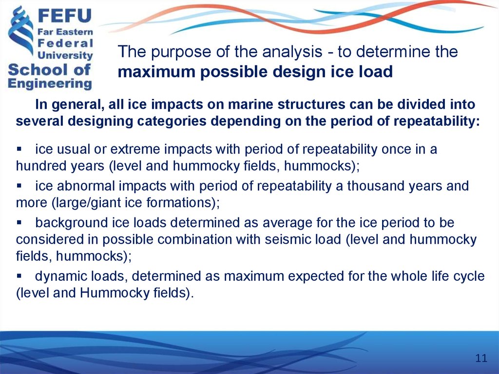
The purpose of the analysis - to determine themaximum possible design ice load
In general, all ice impacts on marine structures can be divided into
several designing categories depending on the period of repeatability:
ice usual or extreme impacts with period of repeatability once in a
hundred years (level and hummocky fields, hummocks);
ice abnormal impacts with period of repeatability a thousand years and
more (large/giant ice formations);
background ice loads determined as average for the ice period to be
considered in possible combination with seismic load (level and hummocky
fields, hummocks);
dynamic loads, determined as maximum expected for the whole life cycle
(level and Hummocky fields).
11
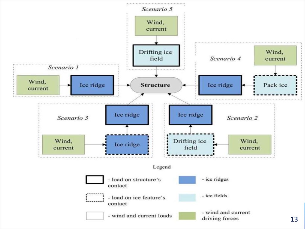
12. Possible scenarios of interaction between an ice cover and structure
1. “Ridge – structure” interaction - a physical model of a total destruction of an Ridge(Scenario 1);
2. “Ridge – structure” interaction - an energetic model of the partial failure of Ridge
(Scenario 1’);
3. Total Load from currents and wind on the ice formation which has stopped in front
of a structure. In this case the realization of following designing scenarios is
possible:
- the Ridge which has stopped in front of a structure, is impacted by the drifting ice
fields of various sizes and concentration (Scenario 2),
- “structure – stopped ice formation” system is impacted by external loads from wind
and current (Scenario 3),
- the Ridge which has stopped in front of a structure, is impacted by the pack ice
(Scenario 4),
4. Interaction between a large/giant ice field of rare probability of occurrence and a
structure (Scenario 5).
12
13.
1314. Algorithm steps and numerical realization of model
When developing the algorithm of probabilistic modeling of ice – structureinteraction, the following assumptions were accepted.
1. The ice cover is represented as a stochastic flow with random
combination of ice ridges and ice fields, uniformly distributed over the
water area.
2. The ice ridge with the random geometric, kinematic and strength
parameters approaches the structure with vertical shape, stops in front of it
and refreezes.
3. The ice ridge which had stopped in front of the structure is affected
by the level ice fields of various sizes and concentration.
4. The ice ridge is characterized by the probabilistic parameters: a sail
height, drift velocity, strength of the consolidated part, sizes, strength
parameters of a keel and a sail.
14
15. Algorithm steps and numerical realization of model
5. Ice fields are defined by the probabilistic parameters: ice field thickness h, generaldrift velocity V, size of ice fields D, and ice strength R.
6. The parameters of the ice regime are random values and have been represented
as histograms obtained from field observations in water area of oil&gas deposit. The
limits of the existing parameters of an ice cover are restricted by the values of actual
full-scale data.
7. The deterministic (non-stochastic) parameters are the parameters of structure
(size, width, water depth, etc.) and the physical properties of an ice cover (e.g.,
density, salinity, etc.).
8. Supposed hit of an ice ridge with a structure and stopped ridge with an ice field ice
is determined according to a “rain drop” model. In the probabilistic scenario ice hit is
considered as a random event.
15
16. The generation scheme of random parameters of ice regime by Monte-Carlo method
1617. CALCULATION EXAMPLE (Bekker, Sabodash, Kovalenko OMAE 2013)
Input Data Analysis:Ice conditions. The ice regime to the north-east offshore Sakhalin is very severe in
the southern part of the Sea of Okhotsk. In extreme winters the maximum values of
an ice thickness are about 90÷160 cm, peak values of the ice drift velocity are about
74÷110cm/s, moreover the specificity of ice drift is reversing nature near the area of
oil&gas deposits.
Statistical characteristics of variability of parameters of an ice cover for the PiltunAstokhskoe oil&gas deposit were taken from full-scale data obtained from various
research programs in 1989-2002. Numerical simulation of design values of ice
parameters was made by Monte-Carlo method.
This area is characterized by the permanent ice cover deformation followed by
hummocking and continuous failure of the ice fields. The heights of ridge's sails in
some areas are about 1.5 - 3.0 m, the keel width is 60 m, and the maximum keel
depth is 20-25 m.
17
18. Calculation example
StructureThe “Molikpaq” offshore platform (PA-A) was installed during Phase 1
in 1998.
“Molikpaq” is a converted ice-class drilling rig, previously based in the
Beaufort Sea.
The characteristics of the structure are: 111m × 111m base, 37,523 t
weight, and 30m water depth.
Design global ice load is equal 640 MN, including the local ice pressure
3.0 MPa.
18
19. Histogram of ice loads for “structure - ice ridge - ice field” scenario (Scenario 2)
1920. Cumulative frequency function of distribution of ice load on the probability paper of exponential distribution for 1989-2002
(Scenario 2)Verification - ?
20
21. NON-EXTREME ANALYSIS (Fatigue, Abrasion, Corrosion)
2122. Abrasion Actions of Drifting Ice Cover on Marine Engineering Structures
2223. Ice Abrasion
This is the effect of drifting ice formations on the structure,causing the destruction of the surface of the structure material
23
24. The Concept calculation of depth of abrasion of construction materials by Ice
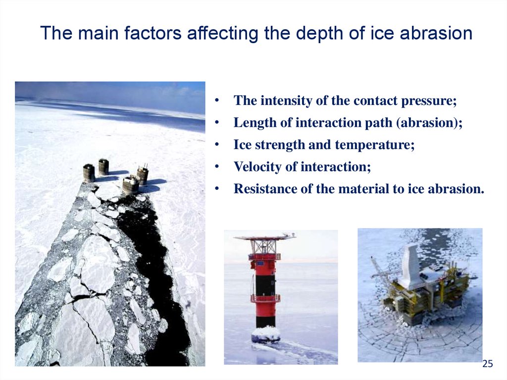
2425.
The main factors affecting the depth of ice abrasion• The intensity of the contact pressure;
• Length of interaction path (abrasion);
• Ice strength and temperature;
• Velocity of interaction;
• Resistance of the material to ice abrasion.
25
26. Ice Impact on Structure (Ice contact pressure)
2627. Probabilistic Imitation Model of Ice Loads Formation
Main Assumptions1. Ice Cover is the Ice Features Combination, Uniformly Distributed on Water
Area With Thickness h, Diameter D, Concentration N, Drift Velocity V.
2. Ice Cover Parameters are the Independent random variables.
3. To calculate the loads and impacts on the sea structure, the calculated
combinations with the determined values of the ice regime parameters are
formed.
4. The time of existence of the calculation Situation is calculated on formula:
tk P(Vk ) P( Dk ) P(hk ) P(tk ) P( N k ) P( Z k ) ts
5. The time of existence of the calculated situation, taking into account the
probability of contact of the ice formation with the sea structure, is
determined by the formula:
N
tc t k
( Dk D) ( L0 D)
2
10 Dk
27
28. Additional assumption
6) For proper calculation of ice loads, three basic groups of probableeffects by drifting ice on supports of marine structures are specified
depending on dimensions of ice formations:
load by broken ice with dimensions up to (Dk ≤ 4d, where Dkdiameter of ice formation, d – diameter of marine structure’s
support)
load by ice floes with dimensions up to (4d < Dk ≤ 500m);
load by ice fields (Dk > 500m);
28
29. Additional assumption
7) The destruction of ice field of h thickness at interface with GBS occurs bybilateral shear of triangular prisms. Shear angle ß is defined by CoulombMohr limit equilibrium theory (Bekker, 1998). The second and following
shear are happened when vertical size of contact zone is equal:
h1
h
a4
where h is sheet ice thickness, m;
έ is ice relative strain rate, s-1 ;
a is empirical coefficient.
29
30. Destruction by bilateral shear of triangular prisms at contact of system of " ice-structure"
Destruction by bilateral shear of triangular prismsat contact of system of " ice-structure"
30
31. Mathematical Models
Models developed to implement the general probability model forcalculation of GBS depth of abrasion are as follows:
mathematical model of mechanical interaction of ice fields with
structure;
mathematical simulation model of ice force formation and
calculation of abrasion path from ice fields;
mathematical simulation model of ice force formation and
calculation of abrasion path from ice floes;
mathematical simulation model of ice force formation and
calculation of abrasion path from broken ice;
mathematical model of abrasion depth calculation.
31
32. Hierarchy of mathematical models for calculation on the Gradual Failure
Simulation modelPhenomenological
models of contact
interaction (destruction)
of ice formations
Model of
distribution of
influence on a
contact zone
The model of the
drift of the ice
cover
Properties of sea ice
(field and laboratory
studies)
Model of probability of
ice formation hitting the
object
Models of wind
and current
influence
Model "a drop of
rain»
32
33. Modeling of ice properties
Phenomenological model theestimated strength of ice
Ice temperature delay
model in the presence of
snow cover
Accounting for the
salinity and structure of
ice thickness
Taking into account the
speed of relative ice
deformations
Temperature distribution
along the thickness of
the ice
33
34. Typical cases of “ice field-marine structure” interaction are as follows:
В. Penetration of structure’s supports into the ice field;В.1 Penetration of the ice block, slowdown before the structure;
В.2 Penetration of the ice block with subsequent acceleration caused by
another ice floe impact impulse;
В.3 Penetration of the ice block and shear of ice floe adjacent to structure;
С. Stand-still of the ice field before the structure;
С.1 Stand-still of the ice block and velocity slowdown;
C.2 Stand-still of the ice block with subsequent moving-off caused by another
ice floe impact impulse;
D. Ice block buckling failure.
E. Open water in front of structure.
34
35. Simulation modeling
The simulation model of the drifting ice cover and its effects on structure,designed to determine the various characteristics of the interaction of the ice cover
and structures, based on numerical simulation of the distribution functions of the ice
regime parameters and simulate all possible situations characterized by a random
combination of values of these parameters.
For each situation, a deterministic calculation of the ice load is performed, using
specially designed mathematical models.
One group of models describes the process of mechanical interaction between ice
fields and structure, and the other describes the process of destruction of ice fields in
contact with the structure and the formation of ice load.
As a result of the “run" of all calculated situations during the operation of the
construction, we obtain the probability distributions of ice loads and their parameters
35
36. Mathematical model of formation of ice loads and impacts (ice fields)
Fbp mkb k vdRk h1Fp nt k1k 2 Fbp
M iVi 2 2( Fi Fw ) Vi t
Vi 1
M i 1
xi Vi t
X i xi
X
M i 1Vi 21 M iVi 2
0 Fi xi 2 2
Vi 1
M iVi M 0Vk
Mi M0
d
dk
2
36
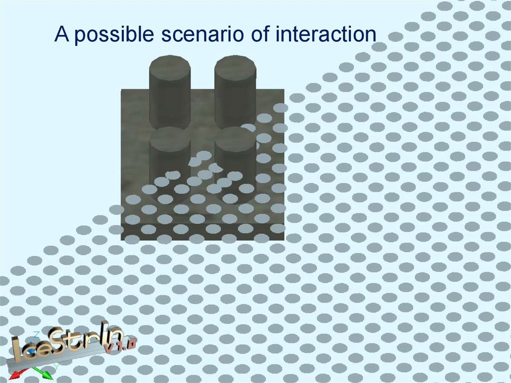
37. A possible scenario of interaction
38. Mathematical model of formation of ice loads and impacts (fragments of ice fields)
Fbp mkb k vdRk h1N>9
dk
Fp nt k1k 2 Fbp
X Vk tc
d
1
arccos
2
2
N<9
kt
X ktVk tc
d rb
Dk L0 d rb
38
39.
A possible scenario of interaction40. Mathematical model of formation of ice loads and impacts (broken ice)
Fbp mkb k vdRk h1N<9
Fсp 0,04Vi h1 mAkb k vRk tan
X ktVk tc
d rb
kt
Dk L0 d rb
d
d k d arctan rb
d
M 0Vk2 2
F
(1 cos( ))
L0
N>9
p 2C tan / 4 ice / 2
40
41.
A possible scenario of interaction42. Scheme to determine the strength of ice depending on temperature
4243. Scheme to determine the strength of ice depending on temperature
Rc1 N 2
Ci
N i 1
43
44. Mathematical model of variability in plane-altitude and in high-altitude variability of ice impacts
4445. Resistance of building materials against ice abrasion
4546. Abrasion Rig
4646
47. Experimental studies of ice abrasion
Abrasion RigConcrete sample
Concrete sample
after test
47
48. Depth dependence of abrasion from pressure and temperature
4849. An empirical model of concrete resistance against ice abrasion
averT
0,0666
0 , 96
Concrete sample after ice abrasion tests and computer visualization of the
sample surface after tests
49
50. General scheme of calculation of depth of ice abrasion
5051. Block diagram of ice abrasion depth calculation
НачалоПараметры сооружения
d,mf, n,
Ввод исходных данных
Параметры расчета
m, ts, dt,
Константы
ρice, φice, δ
Параметры ледовых условий
P(Vk), P(Dk), P(hk), P(Rk), P(Nk),P(Zk)
К=К+1
Параметры расчетной ситуации
Vk;Dk;hk;Rk;Nk;Zk
Время расчетной ситуации
tk=P(Vk)·P(Dk)·P(hk)·P(Rk)·P(Nk)·P(Zk)·ts
Расчет начальных параметров
L0=Dk·(1-(Nk/10)½)/(2·((Nk/10)/π))½) A0=π·Dk2/4 M0=A0·hk·ρ
i=1; ji=1; Xi=0; drbi=0; Li=L0; aai=0; Vi=Vk; Ai=A0; Mi=M0
ДА
tk>dt
Наличие чистой
воды
НЕТ
ДА
aai>0
Проверка прорезания
НЕТ
C
E
Нет
взаимодействия
Vi+1=Vk
НЕТ
Нет прорезания
Vi+1=0
NO
Li+1≤0
B
Расчет ледовой
нагрузки от ледяных
полей
НЕТ
Прорезание
Vi+1=((Mi·Vi2-2·Fi·dt)/Mi+1)½
C.2
ДА
N>6
НЕТ
N>6
В блоке льда есть льдины?
К блоку льда
подошла новая
льдина?
ДА
ji+1=0
Прорезание
Vi=((Mi·Vi2-2·Fi·dt)/Mi+1)½
Add new floe
j=j+1
Vi+1=(Mi·Vi+M0·Vk)/(Mi+M0)
Ai+1=j·A0
aai+1=Dk-Xi+1
Vi+1=Vk
E.1
E.2
Время расчетной ситуации
закончилась?
i=i+1
ti>tk
ti=i*dt
Нет
Продолжаем расчет
ДА
НЕТ
абразии
A
Ai+1=A0
aai+1=Dk-Xi+1+Li-Vk·dt
Vi+1=Vk
B.2
НЕТ
ДА
НЕТ
ДА
B.1
D>500 м
ji+1=ji-1
Li+1=Li-Vk·dt+Vi·dt
Li+1≤0
ДА
B.3
Расчет абразии
dk=π·d/2
σi=Fi/(hk·dk)
li=dxi·sin(α)
δ=f(σ,R)
Δ=δ·li
НЕТ
НЕТ
ДА
D
Добавление нового поля
j=j+1
Vi+1=(Mi·Vi+M0·Vk)/(Mi+M0)
ДА
Расчет длинны пути
взаимодейсвия
dxi=Vi·dt
Xi+1=Xi+dxi
P=(0.4·N)/(Dk2π)·d·Vk·tk
tk=P·tk
Xi+1>(Dk-Kl·(d))
ДА
Накопление
данных
C.1
Vi>0
Проверка скола
Li+1=Li-Vk·dt+Vi·dt
К сооружению подходит
новая льдина?
НЕТ
Расчет ледовой
нагрузки от битого льда
и обломков ледяных
полей
Накопление
данных
Расчет ледовой
абразии
σi=Fi/(hk·dk)
Xk=Krb·Vk·tk
li=Xk·sin(α)
δ=f(σ,R)
Δ=δ·li
Прорезание
Vi+1=Vk
Пройдены все расчетные
ситуации?
НЕТ
Переход к следующей расчетной ситуации
K=Kmax+1
YES
Конец расчета
Формирование
отчета
Конец
51
52. The procedure for calculating the factors affecting abrasion and the depth of abrasion of the material design
The initial data are:• the parameters of structures (size d, form supports m);
• the parameters of the ice cover (the speed of ice drift, V, the thickness of
the ice fields, h, the ice concentration, N, the strength of ice, R, the
diameter of the floe, D);
• sea level fluctuation distribution function (Z (t)).
1. The simulation of the ice regime is carried out by iterating through the
input parameters h, D, N, R, V, Z in such a way as to cover all the
calculated situations, i.e. all possible combinations of parameters. As a
result of the k-th time step (k-th decade) and the I-th combination of
parameters, we simulate the specific situation of the ice regime with the
following parameters: hki, Dki, Nki, Rki, Vki, , Zki.
In addition, the probability of their occurrence is determined:
phki, pDki, pNki, pRki, pVki, pZki
52
53. The procedure for calculating the factors affecting abrasion and the depth of abrasion of the material design
2. The time of existence of the i-th combination of parameters ofthe ice regime tk is determined taking into account the probabilistic
combination of parameters.
3. At each i-th step of the simulation calculation, we model the
process of mechanical interaction of ice formations with the support
of engineering structures with a thickness of hki, the size of ice
fields Dki , concentration Nki, strength Rki and speed Vki, and also
takes into account the process of sea level fluctuations Zki
Consider the process has a duration of tki .
4. On the basis of the data obtained, the process of the construction
material abrasion is simulated. As a result, the abrasion depth of the
structure material S is calculated taking into account the sea level
fluctuations.
53
54. Computer programs for calculation of ice abrasion
5455. Calculation example
Result of calculationDesign GBS for Arkutun-Dagi Field
Result of calculation
55
56. Verification of Mathematical Models and of Ice Abrasion Calculation Methodology
5657. Verification Scheme
Samples of concrete from the objectLaboratory testing of
samples
Analysis of test results
Numerical analysis
Calculation
The results of
numerical
simulation
Model
verification
atural conditions of the area
of installation of beacons
Results of
measurement
of beacon
abrasion
58. Finish Lighthouses
5859. The location of the lighthouses in the Gulf of Bothnia
5960. Nature Conditions of Baltic Sea RAAHE Lighthouse
6060
61. Experimental studies of the resistance of concrete samples taken from the foundations of beacons of ice abrasion
6162. The empirical model of the intensity of ice abrasion
RAAHEaver
T
0,116
OULU 2
1,121
aver
T
0,1467
OULU 3
0 ,808
aver
T
0,2274
1,164
62
63. Results of Calculations (RAAHE)
63Calculation results and observed depth of
ice abrasion
№
1
2
3
Parameter
Raahe
The estimated level, m
- 0,168
The estimated attrition over the
83
44 years of operation, mm
Full-scale
measurements
of
80
abrasion for 44 years, mm
63
64. Results of Calculations (RAAHE)
6465. Realization of Ice Abrasion Calculation Methodology (Sakhalin 1 project)
6566. Ice protection devices
Concrete GravityBase Structure PA-B
Concrete Gravity Base
Structure Lun-A
66
67. The cutting process of ice cover by GBS Lun A
6768. Destruction of steel protection belt on Lun-A from ice abrasion
6869. Destruction of metal protection devices from ice abrasion
Platform PA-APlatform PA-B
69
69
70. Possible options for protection of ice abrasion Decision
STEELICE RESISTANT BELTS
CONCRETE
ICE RESISTANT BELTS
HOW TO CALCULATE?
70
71. The results of calculation of the abrasion depth of concrete by ice for Arkutun-Dagi GBS (Sakhalin 1)
Design GBS Arkutun-DagiDepth of ice abrasion in
40 years (mm)
The length of the abrasion
path for 40 years (km)
Computer 3d visualization of
calculation results
71
72. Ice Resistance Fragment of GBS Legs, scale 1:1
7273. Assessment of the depth of ice abrasion on the example of concrete base Arkutun-Dagi (Sakhalin 1)
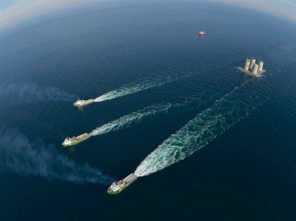
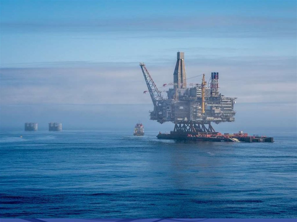
7374. Arkutun-Dagi GBS in floating position
7475.
7576.
77. Platform “Berkut”
7778. Results
ON THE BASIS OF THE ADOPTED CONCEPT AND PROBABILISTIC APPROACH ISDEVELOPED
General simulation probabilistic model of formation of ice loads from drifting
ice cover on sea structures for the entire period of operation;
A phenomenological model of destruction of the ice plate on contact with
structure and the method of determining the rate of change of ice load;
Mathematical model of mechanical interaction of drifting ice fields with the
structure;
The method of determining the number of cycles and loading conditions of
structure and their elements is recommended for practical application;
Mathematical model for determining the distribution of ice loads from ice fields
for the calculation of structures for the gradual failure;
Mathematical model for determining the maximum values of ice loads from
hummocks for calculations for sudden failure;
Mathematical model for calculating the abrasion depth of the structure
material for the entire period of operation;
Verification of methodology and mathematical models on full scale data base.
78