


 industry
Similar presentations:
")


A Mechanistic Model of Cutting Force in the Micro End Milling Process
1. A Mechanistic Model of Cutting Force in the Micro End Milling Process I.S. Kang, J.S Kim, J.H. Kim, Y.W. Seo
Corey Christensen10/10/2007
2. Introduction:
• What is micro end milling? 1mm - .04µm dia• Applications of micro end milling
• Micro end milling vs. Conventional end milling
– Feed/tooth to tool radius
– Cutting conditions
– Detection of tool wear
• Various cutting force analyses
2
3.
• Previous analyses– Analytic cutting force of the conventional end mill as a
function of chip thickness and cutting area, Tlusty et
al
– Analytic cutting force model of micro end mill based
on Tlusty , Bao et al
• Major shortcomings
– Based mainly on differences between tool tip
trajectories
– Ignored the effect of tool edge radius
3
4.
Operator’s tool lifeTool life is measured by:
• Visual inspection of tool edge
• Tool breaks
• Fingernail test
• Changes in cutting sounds
• Chips become ribbony, stringy
• Surface finish degrades
• Computer interface says
- power consumption up
- cumulative cutting time reaches certain level
- cumulative number of pieces cut reaches certain value
4
5. Models & Design Principles
Models & Design Principles• Model based on the tool edge radius
• When depth of cut is close or smaller than
the tool edge radius, the radius effects
cannot be ignored
5
6. Tool edge radius affects cutting mechanisms
• Elastic recovery in the flank face of the work piece• Sliding due to the contact between the tool and the work
piece
• Ploughing due to the tool edge
These cutting mechanisms change the cutter forces in the
feed and normal directions
6
7.
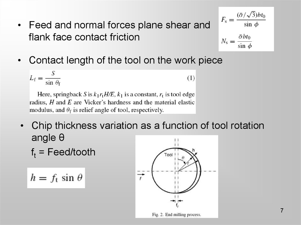
• Feed and normal forces plane shear andflank face contact friction
• Contact length of the tool on the work piece
• Chip thickness variation as a function of tool rotation
angle θ
ft = Feed/tooth
7
8.
• Principal cutting force and thrust cutting force• Final derivation of feed and normal cutting forces
8
9. Experiment
• High speed machiningcenter
• Aluminum work piece
• Forces measured using a
high speed dynamometer
• Forces captured using a
digital oscilloscope
• Cutting origin set using a
CCD camera
• Feed/tooth set between 13µm
• Tool edge radius r = 2µm
9
10. Results
• Previous experiments & models– Conventional cutting
• Normal Force > Feed Force
– Micro cutting according to Bao and Tansel
• Normal Force > Feed Force
10
11.
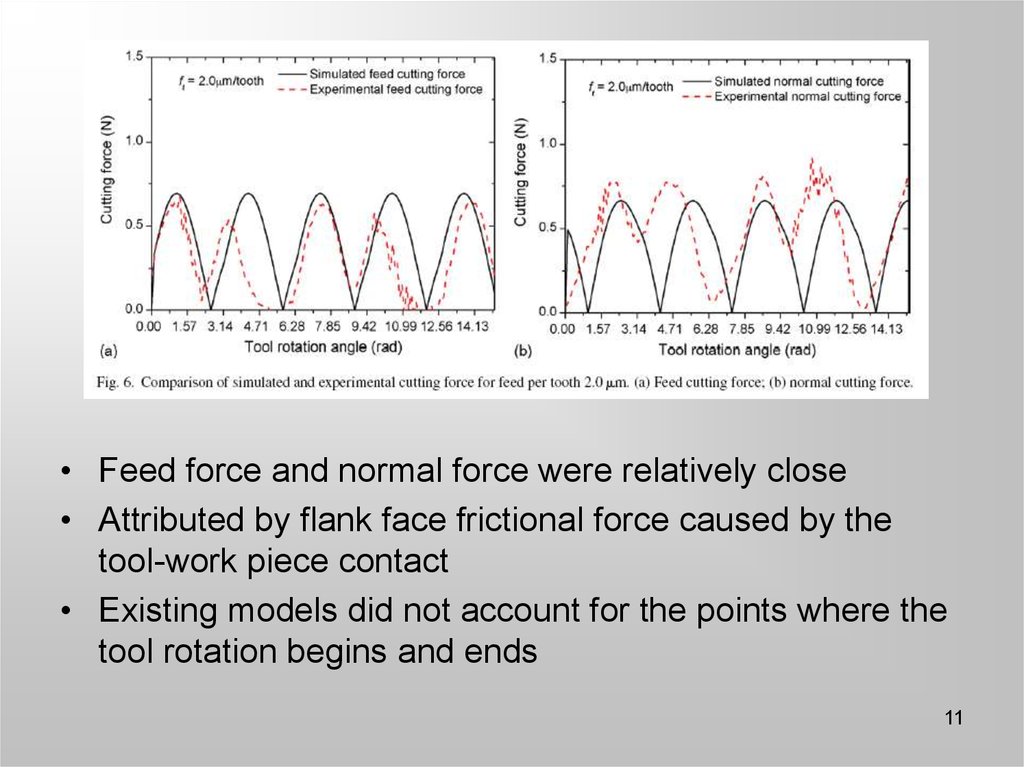
• Feed force and normal force were relatively close• Attributed by flank face frictional force caused by the
tool-work piece contact
• Existing models did not account for the points where the
tool rotation begins and ends
11
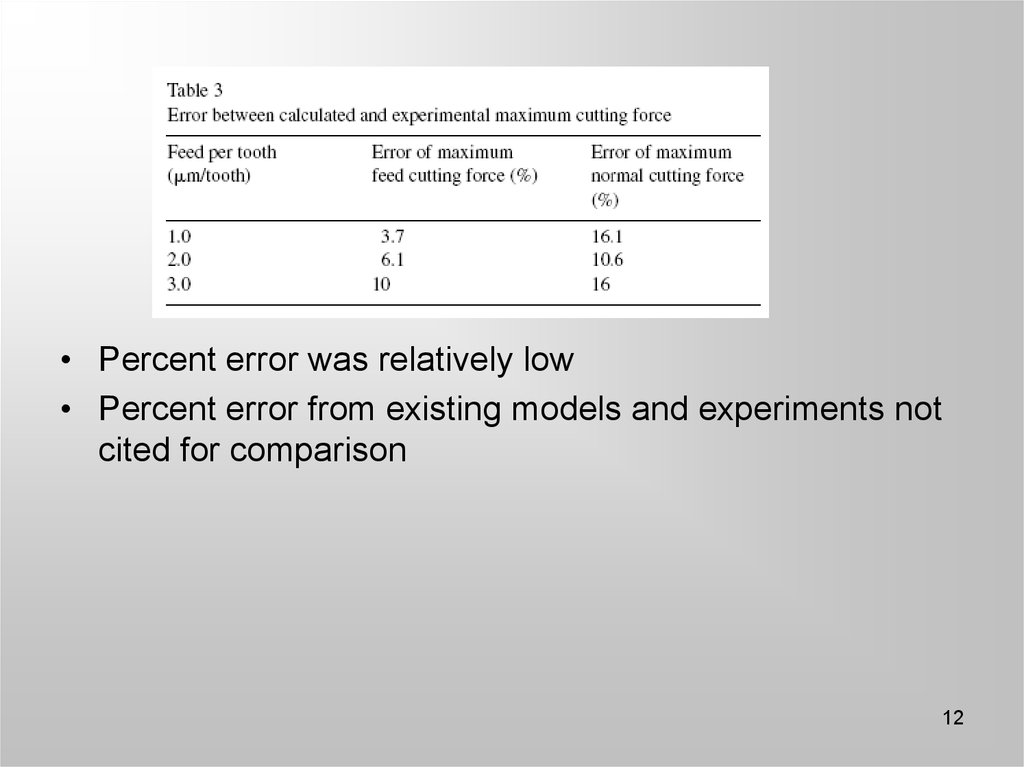
12.
• Percent error was relatively low• Percent error from existing models and experiments not
cited for comparison
12
13. Conclusions
• Derived a model that predicted micro endmilling cutting forces
• Included the tool edge radius effect
• Predicted feed and normal cutting forces
due to the tool edge radius
13
14. Why is it important?
• Help predict tool wear and failure• Extend tool life through known cutting
conditions
Industries affected
• Electronics, biomedical, aerospace, etc
• High precision and accurate dimension
cutting
14