


 industry
Similar presentations:


Process, Power and Marine Division. Piping Task
1. Piping Task
Process, Power and Marine DivisionPiping Task
2. Agenda
Piping HierarchyRoute Pipes
Inserting Components
Routing a Sloped Pipe
Routing Pipes from the P&ID
Placing Instruments
Placing Piping Specialty Items
Placing Taps
Inserting Splits
© 2009. Intergraph Corporation. All Rights Reserved.
3. Agenda Conti’
Manipulating ViewsCreating Spools
Sequencing Objects
Creating Isometric Drawings
© 20049. Intergraph Corporation. All Rights Reserved.
4.
Piping Hierarchy- Piping System
System and Spec Task
- Pipeline System
- Pipe Run
- Features
- Parts/Components
- Ports
- Connections
© 2009. Intergraph Corporation. All Rights Reserved.
5. Piping Hierarchy: Pipe System
A piping system is a way of organizing pipelines within thesystem hierarchy. You can base the piping system on the
area where the pipelines are located or the fluid that the
pipelines carry.
© 2009. Intergraph Corporation. All Rights Reserved.
6. Piping Hierarchy: Pipeline
A pipeline system is a way of organizing pipe runswithin the system hierarchy and controlling the
specifications that can be used within that system. If a
pipeline system exists in a model, you can route the
pipe runs and arrange them as children in the system
hierarchy.
© 2009. Intergraph Corporation. All Rights Reserved.
7. Piping Hierarchy: Pipe Run
A pipe run is a connected series of the pipe featuresthat normally have the same nominal piping diameter
(NPD) and flow direction. All the pipe runs in a model
are governed by the same piping specifications. All the
pipe features belong to a pipe run. One or more pipe
runs together form a pipeline.
Pipe Run 2
Pipe Run 1
6” NPD
4” NPD
© 2009. Intergraph Corporation. All Rights Reserved.
.
8. Piping Hierarchy: Pipe Features
A pipe feature is a logical collection of parts driven bythe pipe specification. While routing a pipe run, you can
place features on the pipe; these features define highlevel design information. The software automatically
selects the specific parts based on the pipe
specification of the pipe run. Features are not displayed
in the workspace explorer because of their ability to own
Run Change
several parts.
Feature
Turn Feature
PIPING HIERARCHY: PIPE FEATURES
Along Leg
Feature
End Feature
© 2009. Intergraph Corporation. All Rights Reserved.
Straight
Feature
9. Piping Hierarchy: Pipe Parts
A piping part is a physical component that comprises afeature and is generally selected by the software.
Figure 3 shows some examples of pipe parts that
represent a section of a piping system. The highlighted
portion in the figure shows a section of the workspace
explorer containing the hierarchy of the pipe parts.
© 2009. Intergraph Corporation. All Rights Reserved.
10. Piping Hierarchy: Pipe Port
Is the actual connection point for the part.Port 1
© 2009. Intergraph Corporation. All Rights Reserved.
Port 2
11. Piping Hierarchy: Pipe Connections
Provide the connectivity model between portsof different components, nozzles and pipes
(welded, bolted, etc...)
Leg 1
Straight
Feature
Generated
parts
Pipe
Turn
Feature
Elbow
Port1
Port1
Port2
Leg 2
C
Port2
Weld
C
Port1
Weld
Port2
© 2009. Intergraph Corporation. All Rights Reserved.
Straight
Feature
Pipe
12. Piping Hierarchy: Overview
© 2009. Intergraph Corporation. All Rights Reserved.13.
Route Pipe: Pipe CommandStart routing a Pipe Run from
- a nozzle/component port
- a point in space
- an existing pipe run
© 2009. Intergraph Corporation. All Rights Reserved.
14. Route Pipe: Cardinal Points
Route a pipe by the top, sides, bottom, or invertelevation of the pipe instead of the pipe
centerline.
Routing by invert elevation
is supported for use in
modeling underground
piping.
© 2009. Intergraph Corporation. All Rights Reserved.
15. Route Pipe: Pipe Run Dialog Box
Define the Pipe Run properties© © 2009. Intergraph Corporation. All Rights Reserved.
16. Route Pipe: Route Pipe Ribbon bar
Designation of commodity options while routingCommodity
option for turn
Angle
control
© 2009. Intergraph Corporation. All Rights Reserved.
Commodity
option for
straight
Piping offset
option
17. Route Pipe: Turn Type Option
Displays the type of turn (Default, Elbow, PipeBend, or Miter).
Default turn type: the system selects the type of
turn as defined in the Ref Data (Default Change
of Direction)
SP3D Piping can check pipe bends as they are
modeled to ensure that they have adequate lengths
for fabrication on an allocated bending machine.
© 2009. Intergraph Corporation. All Rights Reserved.
18. Route Pipe: Graphics Toggle
Route command should only compute the turn part
on commit or (on-going)
Use Shift + F keys to toggle the compute modes
Do not
compute the
turn part
© 2009. Intergraph Corporation. All Rights Reserved.
Compute the
turn part
19. Route Pipe: Length Control Tool
Enter or select a length for the current route path.- Length Lock: Lock or unlock the length field.
- By Default: dynamically displays the current
length of the pipe run from a turn point or a
starting point.
- contains the last 10 values entered by the user.
© 2009. Intergraph Corporation. All Rights Reserved.
20. Route Pipe: Route Using Spherical Coordinates
Relative Tracking Mode© 2009. Intergraph Corporation. All Rights Reserved.
21. Route Pipe: Offset Value
Offset Control ToolIf the reference object is a planar surface or linear
element, the offset distance is measured from the
surface or line to the indicated reference plane on the
pipe being routed. Five offset reference are available.
An offset SmartSketch point is found on either side of
the referenced plane or linear element.
North
© 2009. Intergraph Corporation. All Rights Reserved.
All Rights Reserved.
22. Route Pipe: Offset value
How the Solver finds the offset:© 2009. Intergraph Corporation. All Rights Reserved.
23. Route Pipe: SmartSketch
© 2004. Intergraph Corporation. All Rights Reserved.24. Route Pipe: PinPoint
PinPoint provides coordinate inputs to theroute command.
x,y,z coordinates are relative to Target Point.
Relative Tracking Mode.
© 2004. Intergraph Corporation. All Rights Reserved.
25. Route Pipe: Smart Step Ribbon Bar
• Angle lock in Route command should remainlocked until manually unlocked
• Working plane should be set to plan plane
when sloped run is created
• Compute offset of piping from duct and
cableway routes
Working
Plane
Control
© 2004. Intergraph Corporation. All Rights Reserved.
Angle
Lock
Offset
Control
26. Route Pipe: Working Plane Control Tool
Constrains the route path to a specific plane.Ctrl + Keyboard
1 - Plane Plane
Route plane
2 - Elevation Plane
3 - Section Plane
4 - Plane by Turn/Branch
5 - Plane by Three Points
6 - No Plane
© 2004. Intergraph Corporation. All Rights Reserved.
27. Pipe Select Command
Provides specific filters:Workspace Explorer (set the
filter to all and key in the string
in the field to find an object).
Tools > Select by Filter
© 2004. Intergraph Corporation. All Rights Reserved.
28. Delete a Pipeline
Deleting a pipeline deletes all pipe runs,features, and parts associated with that pipeline.
© 2004. Intergraph Corporation. All Rights Reserved.
29. Delete a Pipe Run
Deleting the run deletes all features (andthereby all parts) belonging to the run.
The software attempts to maintain the design
integrity of the model by adjusting all previously
connected features.
© 2004. Intergraph Corporation. All Rights Reserved.
30. Delete Straight Features
Example:© 2004. Intergraph Corporation. All Rights Reserved.
31. Run To or From End Features or Nozzle
When you select an end feature during thecreation of a pipe run, the Route Pipe command
joins the run with the end feature and inherits
the properties of the run that the end feature
belongs to.
© 2004. Intergraph Corporation. All Rights Reserved.
32. Routing To or From a Straight Feature
Use the Route Pipe command• Branch on Pipe Run
© 2004. Intergraph Corporation. All Rights Reserved.
• Intersect to Branch
33. Insert Component
Insert command inserts a component interactively.In-line components (Valves, Tees, Reducers);
Change of direction (Elbows, Miters, Bends); End
Components (caps and plugs); Strainers (Ystrainers, Basket Strainers) etc…
© 2004. Intergraph Corporation. All Rights Reserved.
34. Insert Component :Insert Component Ribbon Bar
SelectFeature/EF
or Nozzle
Comp
Rotation
Select
Component
Type
Insertion
Point
Display the
Pipe Run
Toggle
Ports
End the
command
Displays a list
of available
component
© 2004. Intergraph Corporation. All Rights Reserved.
Display
Component
Tag
Specifies a
port to be the
insertion
point
35. Insert Component : Graphical Positioning
• Reference Position option:The system should slide the component along the
path so that the select position (example: Origin) is
located at the insertion point.
Flip option: port 1
Reference position: port 1
Reference position: origin
Reference position: port 2 or port 3
© 2004. Intergraph Corporation. All Rights Reserved.
36. Insert Component : Graphical Positioning
• Flip option:Toggles through the ports available for the
component being inserted. As each port is
toggled, the component is oriented so that the
selected port is aligned along the axis of the leg on
which it is being inserted.
Reference position: port 1
Flip option: port 1
Flip option: port 2
Flip option: port 3
© 2004. Intergraph Corporation. All Rights Reserved.
37. Insert Component : Mating
Mating part ports / endterminus available in the
Ref Position list.
Mating
Ports
© 2004. Intergraph Corporation. All Rights Reserved.
38. Insert Component : Positioning & Placement
Insert Component : Positioning & PlacementInsertion of a new component at an equipment nozzle
Example:
Since a suitable straight feature exists on the leg, the check
valve and its connecting flange are repositioned and the gate
valve is inserted.
© 2009. Intergraph Corporation. All Rights Reserved.
39. Routing Sloped Pipe
Underground piping collects drains from funnels or catchbasins and transports them to a disposal point. Since there is
no pressure in this piping system, the pipe must slope for
flow.
© 2009. Intergraph Corporation. All Rights Reserved.
40.
Routing Sloped PipeSlope format
© 2009. Intergraph Corporation. All Rights Reserved.
41. Routing Sloped Pipe
Specify Slope on New Run Properties page© 2004. Intergraph Corporation. All Rights Reserved.
42. Routing Sloped Pipe: Slope Direction
Specify Slope DirectionTurn Slope Lock On/Off
© 2009. Intergraph Corporation. All Rights Reserved.
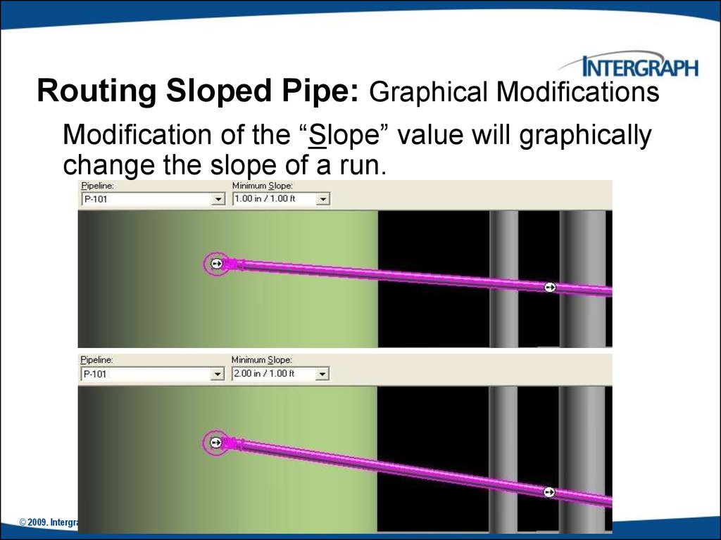
43.
Routing Sloped Pipe: Graphical ModificationsModification of the “Slope” value will graphically
change the slope of a run.
© 2009. Intergraph Corporation. All Rights Reserved.
Reserved.
44. Routing Sloped Pipe :Angle Control Tool
Enter or select an angle for the current route path.- Angle Lock: Lock or unlock the Angle field.
- By Default: Dynamic readout of the current
bend angle as defined by the cursor.
- The angle field can only be 0 or 90 deg if the working plane
is set to NO Plane.
© 2009. Intergraph Corporation. All Rights Reserved.
45. Piping Practice Labs
Route PipesInserting Components in a Pipe Run
Routing Sloped Pipe
© 2009. Intergraph Corporation. All Rights Reserved.
46. Integrated Environment
While designing or creating a plant in SP3D, you can reuse existing datafrom other design or authoring tools rather than creating a model from
scratch. SmartPlant Foundation (SPF) supports the integration of
engineering tools, such as SmartPlant® P&ID, SP3D, SmartPlant
Instrumentation, and Aspen Zyqad. This integration addresses the flow
of data as it moves from one engineering application to another through
its lifecycle.
In an integrated environment, you publish and retrieve data from and to
SP3D by using a central repository. During a publish operation, data such
as drawings, reports, and 3D models transfers to a central repository.
During a retrieve operation, the system retrieves P&IDs, Plant Break
Down Structure, Project List, Work Breakdown Structure, Electrical
Cable Schedules, and Instrumentation Dimensional Data Sheets from
the central repository
© 2009. Intergraph Corporation. All Rights Reserved.
47. Retrieving Data from a P&ID
Retrieving Data from a P&IDYou can retrieve piping, instrumentation, and equipment data
from P&ID in the integrated environment. You can use P&ID
to access items, such as equipment, piping information, and
SmartPlant Instrumentation dimension data, to help create
the appropriate 3D design objects. For example, after you
retrieve data from P&ID, you can use the P&ID File Viewer
window in SP3D for guidance in routing pipes, inserting
components and instruments, and placing equipment in the
3D model.
© 2004. Intergraph Corporation. All Rights Reserved.
48.
SP3D Routing From P&IDUsers can import SmartPlant P&ID pipeline
and component data into the 3D active data.
© 2004. Intergraph Corporation. All Rights Reserved.
49. Insert Component by its Engineering Tag
The engineering tag will be available on the P&ID,and may be used to select a piping commodity
from the Piping Specification.
© 2009. Intergraph Corporation. All Rights Reserved.
50. Instrument & Piping Specialty Placement
Instrument & Piping Specialty Placement• We have two types of piping specialty/instrument
Parts:
- 1. Stock item: Stock items represent those piping
items that are purchased from a manufacturer’s
catalog, where no real engineering is required
other than selecting the correct size, material, etc.
- 2. Custom-engineered item: custom engineered
items are built items according to the process.
© 2009. Intergraph Corporation. All Rights Reserved.
51. Instrument & Piping Specialty Placement
Instrument & Piping Specialty Placement• Placing piping specialty/instruments
© 2009. Intergraph Corporation. All Rights Reserved.
52. Instruments
Placement of Instrument ItemsOn the Fly
© 2009. Intergraph Corporation. All Rights Reserved.
53.
InstrumentsPlacement of Instrument
Items On the Fly: User is
able to provide item dims.
© 2009. Intergraph Corporation. All Rights Reserved.
54. Placing Piping Specialty Items
Specialty items are piping components that are not definedas a part of piping specification. Just like instruments, you
can place specialty items in a pipeline to perform a specific
task.
Isolating Gate Valve
© 2009. Intergraph Corporation. All Rights Reserved.
55. Piping Specialty Items Types
Stock specialty items: These items representsthe piping items purchased from a manufacturer’s
catalog, where no real engineering is required other
than selecting the correct size and material.
Custom specialty items: These items are
typically driven by parameters. Therefore, you can
change their size and shape after placing them in
the model.
© 2004. Intergraph Corporation. All Rights Reserved.
56.
Placing Piping Specialty Items:Properties
Placement of Specialty Items On the Fly
© 2009. Intergraph Corporation. All Rights Reserved.
57. Insert Tap
Use this command when in need to tap a drain, vent, or instrumentconnection. Used to place taps on all piping components; elbows,
tees, caps, valves, pipes, and so forth; except for mating parts.
© 2009. Intergraph Corporation. All Rights Reserved.
58. Inserting Splits : Insert Split Command Bar
The Insert Split command cuts a straightpipe and connects the parts by a weld joint
or a takedown joint.
© 2009. Intergraph Corporation. All Rights Reserved.
59. Inserting Splits : Insert Split Ribbon Bar
Feature BreakInsertion Point
Select
Feature
Takedown
joint
Display the
Pipe Run
Welded
Joint
© 2009. Intergraph Corporation. All Rights Reserved.
Display the
type of split
Displays a list
of available
option items
for the split
60.
Inserting Splits : Attribute BreakThe Insert Split command can also be used to
create a feature break. This makes it possible
to stop heat-tracing, insulation, or a surface
coating at an arbitrary location along the pipe
instead of at a weld or other break in the line.
© 2009. Intergraph Corporation. All Rights Reserved.
61. Inserting Splits : Attribute Break
Edit Pipe Run properties during modeling tocreate an attribute break.
When the run properties are changed, the corresponding
feature properties are automatically changed as well.
When NPD is changed, reducers are selected from the
spec to satisfy the NS change.
© 2009. Intergraph Corporation. All Rights Reserved.
.
62. Piping Practice Labs
Routing Pipes from P&IDPlacing Piping Instruments
Placing Piping Specialty Items
Placing Taps
Placing Splits
© 2009. Intergraph Corporation. All Rights Reserved.
63. Piping Manipulation : Edit Straight Features
Moving a SF moves the entire leg to which the feature is
connected.
The move direction is always perpendicular to the axis of the SF.
A branch feature (BF) connected to the moved leg maintains its
original angle.
Movement stops when parts on the associated leg overlap, or
when they overlap with adjacent parts on connected legs.
© 2009. Intergraph Corporation. All Rights Reserved.
64. Piping Manipulation : Edit End Features
Moving the end feature by key in the length© 2009. Intergraph Corporation. All Rights Reserved.
65. Piping Manipulation : Edit Run Change Features
You can move the RCF along the associatedstraight feature. As you move the feature, the
RCF appears in dynamic mode.
© 2009. Intergraph Corporation. All Rights Reserved.
66. Piping Manipulation : Editing Features
Shift – Select CommandMove selected legs
- Point along tool
© 2004. Intergraph Corporation. All Rights Reserved.
67. Piping Manipulation : Editing Features
Shift – Select CommandMove along the leg the selected items
© 2009. Intergraph Corporation. All Rights Reserved.
68. Piping Manipulation : Editing Features
Shift – Select CommandTurn off the moving along the leg
© 2009. Intergraph Corporation. All Rights Reserved.
69.
Piping Manipulation : Part ModificationMating parts can be changed to base parts using
either the ribbon or the property page.
Mating Parts: Depend of a
parent component for
placement, i.e. if parent valve
is deleted, mating flange is
also removed.
Base Parts: Independent
from mating component, i.e. if
connecting valve is deleted,
flange remains.
© 2009. Intergraph Corporation. All Rights Reserved.
70.
Piping Manipulation : Item ReplacementOperator may replace item with another of same type
Presentation of only one short code for a particular item.
If a component has been generated automatically by the
solver, the user sees two entries in the Type list for that
object: one with a "Default" suffix signifying that this part is
rule generated and one without the suffix.
© 2009. Intergraph Corporation. All Rights Reserved.
71.
Piping Manipulation : ModificationNew Enhancement in V4
Ability to rotate components after insertion
Dynamic
© 2009. Intergraph Corporation. All Rights Reserved.
.
Key-In
72.
Piping Manipulation : ModificationNew Enhancement in V4
• Copy/Paste commands are available
• Mirror Copy command is available
• Creation of a connection (geometry permitting)
when multiple objects are moved and placed on
another object
© 2009. Intergraph Corporation. All Rights Reserved.
73.
Piping Properties : PropertiesRight clicking on pipe run or Selecting Pipe run
and selecting properties on the Route pipe
ribbon bar. feature brings up menu when in
Route Pipe environment
© 2009. Intergraph Corporation. All Rights Reserved.
74. Piping Properties :Edit Properties Command
Edit Pipe Run properties.Features inherit the
common properties of
the run by default.
© 2009. Intergraph Corporation. All Rights Reserved.
.
75. Piping Properties : Flow Direction
Flow DirectionDownstream is the direction from the start to the
end of the run
Bi-directional, Upstream, Downstream, No flow, Undefined
© 2009. Intergraph Corporation. All Rights Reserved.
76. Piping Properties : Edit Properties Dialog Box
Insulation© 2009. Intergraph Corporation. All Rights Reserved.
77. Piping Properties : Edit Properties Dialog Box
Edit Pipe Run propertiesRelation Tab displays all the relationships defined for
the selected pipe run.
© 2009. Intergraph Corporation. All Rights Reserved.
78.
Piping Properties : Edit PropertiesDialog Box
• Pipe cut lengths to
reflect lining & weld
gap
© 2009. Intergraph Corporation. All Rights Reserved.
79.
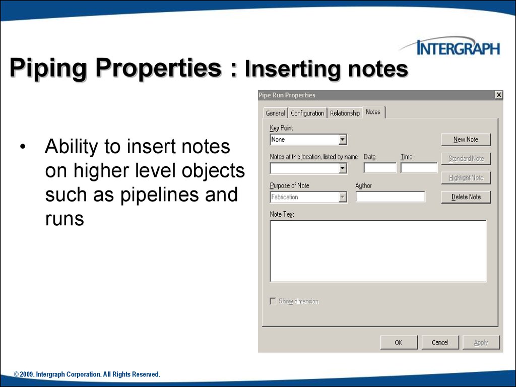
Piping Properties : Inserting notes• Ability to insert notes
on higher level objects
such as pipelines and
runs
© 2009. Intergraph Corporation. All Rights Reserved.
80. Creating Spools
Generation of Spools• Generate Spools
© 2009. Intergraph Corporation. All Rights Reserved.
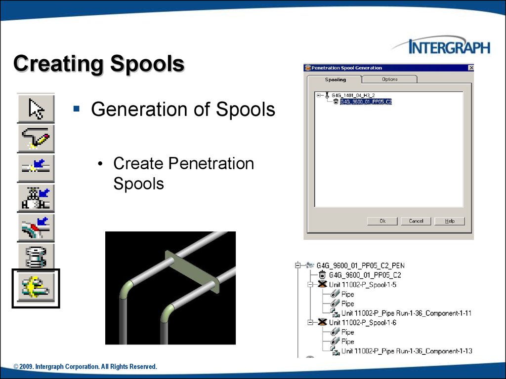
81.
Creating SpoolsGeneration of Spools
• Create Penetration
Spools
© 2009. Intergraph Corporation. All Rights Reserved.
82.
Creating SpoolsNaming of Spools
Spooling options always
default to those defined in
the Catalog with
interactive setting
changes persisting for the
current session only.
© 2009. Intergraph Corporation. All Rights Reserved.
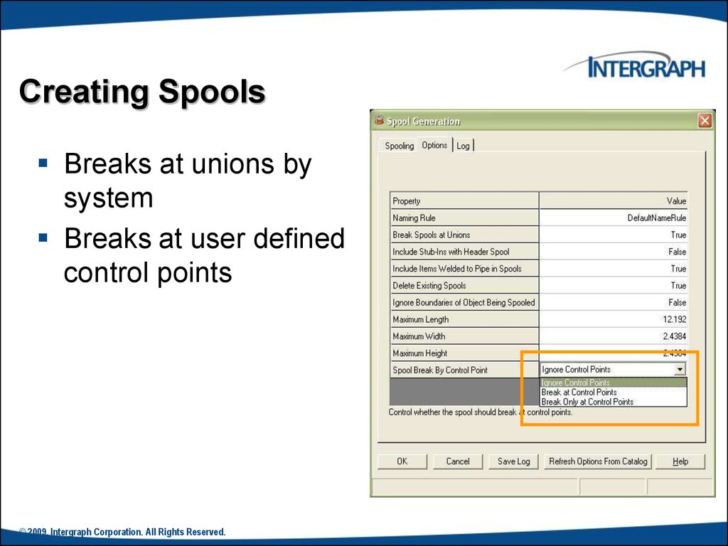
83.
Creating SpoolsBreaks at unions by
system
Breaks at user defined
control points
© 2009. Intergraph Corporation. All Rights Reserved.
84.
Sequence ObjectsRenames objects in the selected pipeline,
pipe run, or spool such that the names are in
order. You can select to sequence the
objects based on flow direction or topology.
© 2009. Intergraph Corporation. All Rights Reserved.
.
85.
Materials ReportsUsers can easily extract materials lists for review
from their modeled pipelines.
© 2004. Intergraph Corporation. All Rights Reserved.
86. Piping Practice Labs
Manipulating Piping ObjectsCreating Spools
Sequencing Objects
Creating Isometric Drawings
© 2004. Intergraph Corporation. All Rights Reserved.
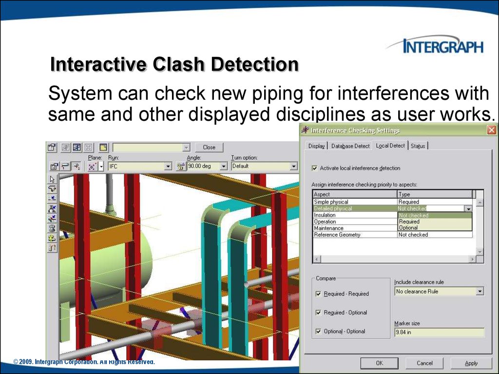
87.
Interactive Clash DetectionSystem can check new piping for interferences with
same and other displayed disciplines as user works.
© 2009. Intergraph Corporation. All Rights Reserved.