


 industry
Similar presentations:

A tentative model of technology improvement in ferro- alloys manufacturing process & the business way forward
1. A TENTATIVE MODEL OF TECHNOLOGY IMPROVEMENT IN FERRO- ALLOYS MANUFACTURING PROCESS & THE BUSINESS WAY FORWARD
A TENTATIVE MODEL OF TECHNOLOGY IMPROVEMENT INFERRO- ALLOYS MANUFACTURING PROCESS & THE BUSINESS
WAY FORWARD
Presented by ........
Dr. A. K. MAHAPATRA
Director (Technical & Administration)
B C MOHANTY & SON Pvt, Ltd., CUTTACK, ODISHA
Chromite Mines at Kamarda (Jajpur) & Ferro Alloys Plant at
Baliapal(Jajpur)
Mobile No - 7008081968, 9437296032
E Mail ID - akmahapatra16@gmail.com
2.
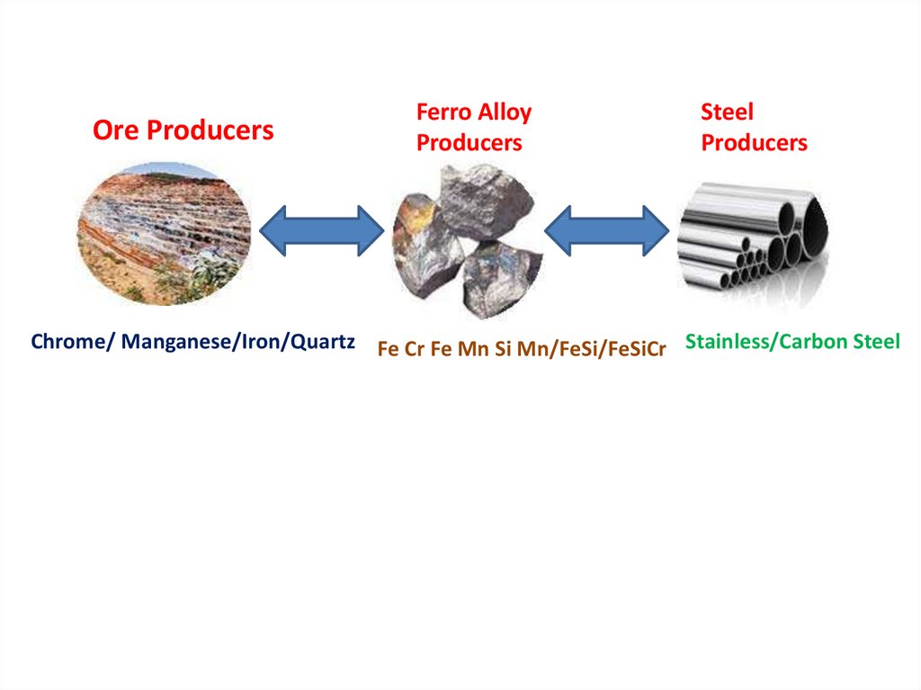
Ore ProducersFerro Alloy
Producers
Steel
Producers
Chrome/ Manganese/Iron/Quartz Fe Cr Fe Mn Si Mn/FeSi/FeSiCr Stainless/Carbon Steel
3. Issues with Indian Ferro‐alloys Industry
4. VARIOUS CHALLENGES FACED BY THE INDIAN FERRO ALLOY INDUSTRY
40% CostRaw
Material
Ore
Source
Non
Profitable
markets
Waste
utilization
Ferro
Alloy
Producers
Labour
And
Logistics
Power
Captive
Vs. Grid
Producti
on
Issues
40% Cost
5. MASTER PLAN FOR SURVIVAL
DEPLETION OF HIGH-GRADE ORELow grade beneficiation
Agglomeration
Sintering
6.
7. Agglomeration & Productivity Improvement for Manganese alloy
Agglomeration &Productivity Improvement for Manganese alloy
Investment in beneficiation & use of agglomerated feed
• Agglomerates offers better reducibility
• Lowers the specific power consumption
• Helps to attain smooth furnace operation
Productivity improvement by having large size of Furnaces
• Smaller furnaces have low per capita output
• Single furnace having high transformer capacity desirable
than operating several small furnaces
• Raw materials preparation and handling systems must also
be modernized
8. Waste Heat Utilization & Raw material Handling
Waste Heat Utilization & Raw materialHandling
Minimizing heat loss and use waste gases for power
generation
• Closed furnace should be adopted than open furnaces
• Will lead to reduce heat loss from the furnace and enable
recovery of latent heat in exhaust gases
Proper handling of raw material
• Saving raw materials from adding moisture
• Low moisture level in raw materials reduces specific power
consumption and specific consumption of reductants
• Gives steady slag and metal composition
9. MARCHING FOR CONSERVATION OF MINERAL
10. MARCHING FOR NEW INNOVATION
• Waste management of Manganese ore <25%Mn & Innovative commercial technologies for
production of products useful for Agriculture
MnSO4 for agriculture
11. EXPERIMENT OBSERVATIONS FOR MANGANESE ORE SINTERING
• Low yield with 100% belt spillage material forsintering.
• Good sinter formation with coke fines rather than coal
fines.
• High yield is obtained by sintering 100% of high
grade manganese ore fines.
• Poor quality of sinter is observed with high
siliceous material in the charge blend.
• Environmental aspects are very big challenges in
sintering operation
12. Experiment Conclusion
• Raw material belt spillages can be sintered in• combination with high grade Mn ore fines only.(Ratio
of 20 : 80).
13. IMAGES OF SINTERING PROCESS
14. IMAGES OF SINTERING PROCESS
15. IMAGES OF SINTERING PROCESS
16. IMAGES OF SINTERING PROCESS
17. IMAGES OF SINTERING PROCESS
18. IMAGES OF SINTERING PROCESS
19. IMAGES OF SINTERING PROCESS
20. Agglomeration of Beneficiated Manganese Ore Fines
SINTERINGMicro‐Granulation is a required to sinter the
beneficiated Mn Ore fines.
• An acceptable grade sinter (TI : ~70, AI :~10%)
can be produced using 10% coke and Mn ore
fines.
• Return fines usually generated between
11‐13%.
• Feasibility studies has been done for a sinter
plant and few sinter plants are also in operation
in India and abroad.
21.
BRIQUETING• Mn ore briquettes were produced and trial
conducted in different Ferro Alloys Plant.
• 10‐15 % briquette usually charged in burden
(40 kg out of ore burden of 640 kg ).
• No operational problem was faced but
increased amount of briquettes can be
harmful for closed furnace.
• Many Small scale players are briquetting the
fines and using in SiMn product
22. Mn‐ORE BENEFICIATION‐ NEW TECHNOLOGIES
Physical Beneficiation• a) Automatic Ore Sorter
• b) Electrostatic Separation
• c) Magnetic Flocculation
(a)
(b)
(c)
23. Mn‐ORE BENEFICIATION‐ NEW TECHNOLOGIES
Pyrometallurgical Route• Magnetic Separation
• Reduction Roasting
24. Mn‐ORE BENEFICIATION‐ NEW TECHNOLOGIES
Hydrometallurgical MethodsLeaching :
Reducing agents natural gases, oxalic acid, methanol, carbohydrate, coal, graphite, sulphur
dioxide, hydrogen, cornstalk, etc., and then the product was leached with sulfuric acid,
HNO3, HCl etc.
Floatation :
The chemicals of pertrolium, sodium sulphonate and oxidized paraffin soap are used to
catch rhodochrosite in floatation dressing.
New Methods : Physicochemical Beneficiation
25.
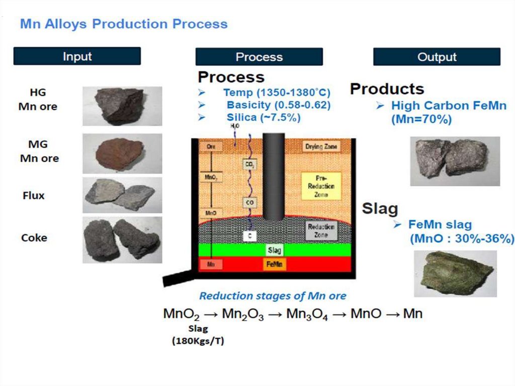
26. PROCEDURES AT FERRO MANGANESE PLANT
27. OUTOTEC PROCESS
28. ENERGY EFFICIENT PROCESS FOR PALLETISING AND SINTERING
29. PREHEATING OF THE CHARGE
30. SEALED SUBMERGED-ARC FURNACE
31. POWER CONSUMPTION IN SMELTING
32. PROCESS IMPROVEMENTS TOWARDS MINERAL CONSERVATION
• Wide variation in the low grade Chrome Ore Quality- Buffer Management & Proper Blending
• Good Process Control to Minimise Losses
- Data Bank Generation on Process – Generation of Circuit data
- Distributed Control System (DCS),
- Floatex Density Separator
- TQM Approach – Shift wise Plant performance Monitoring ( Daily management )
- Optimization of Process Parameters – such as mill speed, ball size, ball load & pulp
density of ball mill
• Recovery of Ultra Fine Chromite Particles
- Wash water Spirals, and Vacuum belt filter
• Tailings Disposal
-We adopted tailings de-watering technology using Press Filters
• Reprocessing / Reuse of Stockpiled Tailings
• - We have developed Tailings Beneficiation process.
33. IMPROVEMENT JOURNEY IN BENEFICIATION OF CHROME ORE FOR BETTER MINERAL CONSERVATION
IMPROVEMENT JOURNEY IN BENEFICIATION OF CHROME ORE FOR BETTER MINERAL CONSERVATIONOBJECTIVES
Economic Use of Mineral
Conservation of Resources for Next Generation
Enviro-Friendly Process Technologies to utilise the resources.
Generate revenues for the stake holders
Statutory Guidelines – IBM, / State Govt
For sustainability of high grade chromite resources and to satisfy
the continuous demand in the future needs, beneficiation of
lean/sub-grade ores is imperative.
• From the mineral conservation point of view, it is necessary to
maximize the utilization of lean grade ore and minimize high grade
ore consumption.
34. BRIQUETTING OF CHROMITES ORE
• In developing a technology for briquetting of chrome ores, it isimportant not only to study the mineralogical and grain-size
characteristics of the chrome ore fines but also to make an
informed choice of the type and quantity of the binder and the
conditions for producing a physically and chemically competent
green and cured briquette.
• The molasses-lime combination binding mechanism involves
the adhesion of molasses due to stronger intermolecular forces
in the sucrose structure that confers the initial green strength.
The second stage which occurs during curing involves the
dissolution of CaO and is characterized by chemical and
polymeric metal complexation to form the calcium saccharate
bond between lime and molasses (hot briquetting - with the
“gluing” action caused by the binder).
35. LAYOUT MODIFICATION OF BRIQUETTE PLANT
• Briquette plant should be set of at back site offurnace building, adjacent to pollution plant.
• Briquette plant should be adjacent to chrome
ore stock shed.
• Briquette plant should be surrounded with thick
green plantation as per the forest and
environment department concern.
• Briquette stacking length should be more
(approx to sixty meters) with as possible as low
drop height (approx- 1.5 mtrs)
36.
• Briquette stacking design should be taken insuch a concrete platform that each lot having
conical base with pneumatic opening
mechanism to down load upon conveyor
which will to be installed in under ground
ways.
• Briquette feeding to day stock bin from
briquette stacking yard should be through
conveyor only keeping close watch that
briquette bin level should be 60-70% always.
37. CHUTE TUBE FILLING PATTERN
• Alternate chute tube should be filled withcharge always which will give initiation for
pre-heating
• Centre chute should be kept full with charge
material always.
• Chute discharging point at furnace hearth
should be minimum level of height from rim
only
38. DESIGN OF POLLUTION PLANT
• Furnace generated flue gas through chimneyducting to pollution plant-bag filters-pollution
stack should be connected to chrome ore shed
with special design of ID-fan.
• Temperature of filtered flue gas is around 100120 degree centigrade which will help for pre
heating of ores at initial stage- minimising FO
consumption in dryer.
39. FURNACE OPERATIONAL POINT OF VIEW
• Required charge level in furnace hearth.• Required electrode length as per the furnace design.
• Good agglomeration of chrome fines to have sufficient
strength in furnace charge burden. This minimises fines
generation(taking 72 hrs cured briquette as a feed) Fines
generated reverts to slag phase thereby reducing chromium
recovery.
Proper stoichiometry calculation as well as choice of
reductants to reduce Cr2O3 in ore, which prevents Cr2O3
losses in slag.
Proper selection of reductants having good reactivity(CRI &
CSR> 50) and strength. This ensures proper reduction of
Cr2O3 in ore
40.
• Increased heat efficiency by suitable selection of currentand voltage ranges with proper electrode tip
positioning(0.7-0.75 x electrode diameter). This improves
thermodynamics and kinetics of reduction.
• Proper selection of slag composition. This reduces Cr2O3
losses to slag and entrapment of Ferrochrome alloy
droplets in slag.
• Proper mineralogy ,size and reducibility of chrome ore
also affects for Cr2O3 losses into slag.
• Since reduction of chrome ore in solid state is significant,
fine ores(chipps) could be used in the furnace. The fine
chrome ore is very readily reduced in solid state before it is
melted, resulting in a low Cr2O3 content of the slag.
41.
• Proper permeability of charge material shouldbe there to effectively utilize CO gas for
reduction. For this size range should be as
close as possible because wide size range
blocks void space in charge materials.
• Too high silicon content in the alloy can
reduce Cr2O3 dissolved in slag by silicothermic reaction and in turn the Si content of
metal decreases, but this reaction is only
significant at high Si contents.
42.
• If the Cr2O3 content in the ore is too high , some ofthe chromium oxide will not be totally reduced and
could be observed in the tapped slag.
• There is an optimum range for the reducibility of
ore. The MgO/Al2O3 ratio is directly proportionate
to the Cr2O3 in the slag. The optimum ore is with
MgO/Al2O3 between 2.2 to 2.5(chrome ore from
Iran). In this range Cr recovery is above 90% and the
energy consumption is the lowest.
• Suitable furnace hearth design parameters like
KVA/square mtrs of hearth area(350-450),
KVA/cubic mtrs ofhearth volume(100-250), KVA/
square mtrs of electrode pitch circle area(15002500) determines optimum smelting conditions
thereby effecting chromium recovery .
43.
• Feed consists of temporarily bound fines withhigher specific surface are which in turn leads
to improved reaction kinetics and
thermodynamics leading to the improved
energy utilisation efficiency and smelt ability.
• Slag chemistry should be maintained in such
pattern that always melting point of
slag(1650-1750 degree centigrade) is >
melting point of metal by minimum 150
degree centigrade
• Metallurgical calculation should be based
keeping metal volume more then the volume
of slag
44.
• Basicity of the slag should be maintainedwithin the range 1.1-1.2 to have the easy
separation as well as easy flow of alloy and
slag.
• Silica in the slag should be maintained within
the range 28-30(basic slag) to obtain the slag
temperature above than metal, that is why
when alloy become low-silicon due to certain
reason, silica increased in slag(above 30)
which lower the slag temperature and
initiates for poor separation of metal and
slag, as a result alloy become porous with
slag contamination.
45.
• Hot alloy tapping should be taken with shortrunner with 2-nos CI- circular pan placing in
series upon a well design track-trolley in
different level and slag to be taken in slag pot
connecting a adjustable runner.
• Tapping planning should be done in such
pattern that all total of alloy of a tapping
should be accumulated in 1st pan.
• Hot alloy carrying pan should not taken for
realeasing before 5-hrs of tapping in order to
avoid leakage.
46. METAL HANDLING POINT OF VIEW
• At metal handling yard (adjacent to tappingbay),slag layer above the metal face on pan
should removed effectively, prevailing to
contamination.
• During sizing (10-40 mm) care should be taken
upon repeated hammering. Taking lumps size
(40-150 mm) order is better.
• Slag contaminated metal should be processed
again and again (screening as well as picking)
as maximum as in the metal handling yard
before sending to jigging plant.
47.
• Double jigging should be taken in same seriesafter getting the tailings from two floating
baths(one for size rang of feed 8-20 mm and
other 0-8 mm placed parallely. The double
jigging machine placed on series should take
the material(tailings) from previous two jig’s
output get mixed ( via one intermediate
crusher to have -6 mm size) in one feed
conveyor, which may give you 2-3 % of metal
output of total tailings get fed.
48. REDUCTION REACTION INSIDE FURNACE HEARTH
. SiO2 + C = SiO + CO2. SiO + 2C = SiC + CO
3. 2SiO2 + SiC = 3SiO + CO
4. SiO + SiC = 2Si + CO
5. SiO2 + 2 C = Si + 2 CO
6. Fe2O3 + 3 C = 2 Fe + 3 CO
7. A1203 + 3 C = 2 Al + 3 CO
8. CaO + C = Ca + CO
MnO2
Mno + C = Mn + CO
Mn2O3
MnO (Low oxidation statae)
49. RATE OF SMELTING REACTION
Solid- Gas reaction at (750-1000)degree centigradeStability of material at hot bath
Having more porosity
Having more surface area
Reductant & Flux should be in close proximity( Composite
Briquette- Flux + Reductant grounded to 175 micron size
then taken with as usual 6-mm ore to make composite
briquette in press with the application of binder)) – drop of
specific power by 200-250 Kwh
Preheated as well as in same vicinity (palletising- all three
components, ie- ore, flux & reductant are grounded to 175
micron then sintered palletising at steel belt) – drop of
specific power by 450-500 Kwh.
50. CONCLUSION
Maximum portion of the income of Ferro-alloy manufacturers istaken away by electricity. Hence the aim of any metallurgist is to
innovate and try to adopt processes which will help bring down
the power consumption as power is precious (40% cost) in
smelting reaction process or to use cheapest source of energy in
pursuit of this –
1)SHOWA DENKO, 2) OUTOKUMPU which was later modified by Xstrata processes were developed. Now one has to try for solid
state reduction using natural gas along with Nitrogen & Hydrogen.
This should be the latest innovation. As charge pre-heating origin
from Japan , Outokumpu procedure origin from Finland and later
on X-strata (complete premus process)origin from South-Africa
keeping an unique ambition of Sp.power reduction/cost