


 industry
Similar presentations:


Set Mat DIY Installation instructions
1. Set Mat DIY Installation instructions
Included in each Kit:Under Tile Heating Mat
24/7 Programmable Thermostat (TH1)
* TR8 Touch Screen available on request.
Continuity Tester (Alarm)
Adhesive Tape
Adhesive Spray
Instructions
Beautifully warm floors for New
Homes and Renovations
Tiles: Granite: Marble: Parquet: Vinyl: Cork:
2. Please read the instructions prior to your installation : The incorrect installation of the heating element may lead to damage
and would invalidate your warrantyGeneral:
1. The heating mat must only be installed as per the hotwire instructions.
2. The heating mat MUST NOT be cut or shortened or the cold tail join be put
under any strain
3. In accordance with the local electricity laws an authorised electrician must
carry out all prescribed electrical work.
4. Your Hotwire element is classified as an electrical appliance. You are not
required to be an electrician to install the element. But all electrical
connections including the connection of the thermostat must be
undertaken by a licensed electrician.
5. IMPORTANT: A certificate of Compliance (COC) must be issued by the
electrician once the installation has been completed. Your electrician may
need to check and test the mat installation prior to any floor covering
being laid including the screed.
6. The design wattage for Hotwire mats is 150 watts per m2.
7. The mat width is 450mm wire to wire.
8. Subfloor: It is essential that the subfloor is sufficiently rigid to support the
heating elements and not allow unnecessary movement.
Net M2
Covered
Floor
Area
Watts
Ohms
Amps
1
150
352.67
0.65
1.33
200
264.5
0.87
1.67
250
211.6
1.09
2
300
176.33
1.3
2.33
350
151.14
1.52
2.67
400
132.25
1.74
3.33
500
105.8
2.17
4
600
88.17
2.61
4.67
700
75.57
3.04
5.33
800
66.13
3.48
6
900
58.78
3.91
6.67
1000
52.9
4.35
8.33
1250
42.32
5.43
10
1500
35.27
6.52
3.
Floor Preparation:1.
2.
3.
4.
Floors must be entirely clean, dry and level. If necessary sand or grind the floor first.
Clean working surfaces will provide good adhesion.
If a timber subfloor is being used, then we recommend tile and Slate underlay being
installed prior to the elements to give the floor the rigidity required. This is
especially important if the subfloor is tongue and groove flooring.
Water proofing membrane requirements are determined on installation methods and
are subject to local council requirements/regulations.
Where there is no water proofing, the floor must be painted with primer and allowed
to dry for 30-40 minutes. This will ensure good adhesion for taping down the
element.
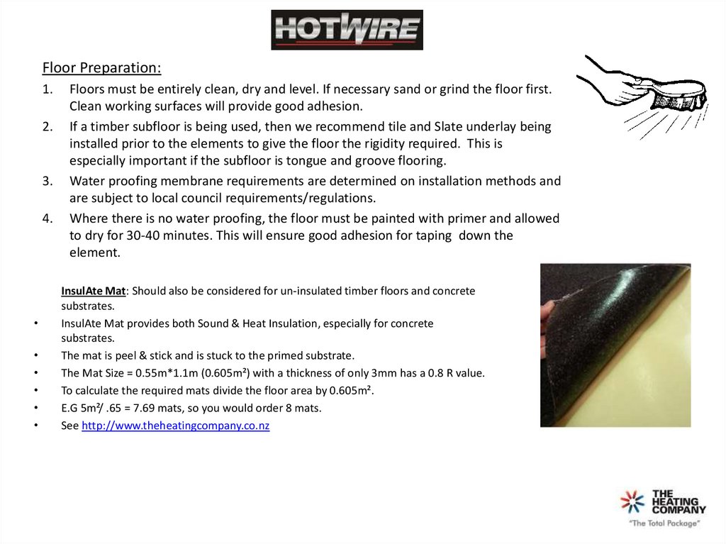
InsulAte Mat: Should also be considered for un-insulated timber floors and concrete
substrates.
InsulAte Mat provides both Sound & Heat Insulation, especially for concrete
substrates.
The mat is peel & stick and is stuck to the primed substrate.
The Mat Size = 0.55m*1.1m (0.605m²) with a thickness of only 3mm has a 0.8 R value.
To calculate the required mats divide the floor area by 0.605m².
E.G 5m²/ .65 = 7.69 mats, so you would order 8 mats.
See http://www.theheatingcompany.co.nz
4.
Marking the floor for mat installation:1. Mark the floor with a marker pen or crayon to show the exact area to be
heated. Be sure not to lay elements in areas that may have floor fixtures
installed after tiling (vanities, showers, toilets, and doorstops etc) The
minimum spacing between 2 runs of the mat is 50mm and the
maximum should be no more than 80mm to achieve efficient heat
distribution.
2. Calculate the exact “net m2 heating area” based on your floor plan Eg:
4m2 = 600 watt heating mat. When measuring the net floor area,
measure off the walls, benches and shower trays the distance you
require.
Prior to the Installation of the element:
1. Before starting, use a multi-metre to check the resistance on the cable
ensuring there is a circuit. Note the correct ohms reading (-5 + 10%)
which is labelled on each cable outer packaging.
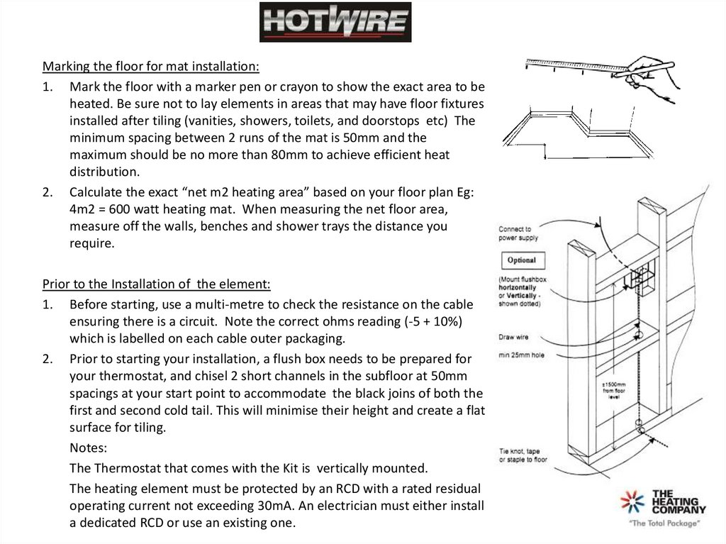
2. Prior to starting your installation, a flush box needs to be prepared for
your thermostat, and chisel 2 short channels in the subfloor at 50mm
spacings at your start point to accommodate the black joins of both the
first and second cold tail. This will minimise their height and create a flat
surface for tiling.
Notes:
The Thermostat that comes with the Kit is vertically mounted.
The heating element must be protected by an RCD with a rated residual
operating current not exceeding 30mA. An electrician must either install
a dedicated RCD or use an existing one.
5.
Prior to installation continued…..3.
4.
Plan your laying path in advance, starting directly below your flush-box position. Where you start is
where you finish.
You can lay the mat in any configuration you want as long as the spacing is even over the total area to
be heated. See examples below.
6.
Installation of the element:1. Secure the heating element using a hot glue gun or tape .
2.
3.
Make sure no part of the element lifts from the floor surface. This will ensure no damage occurs while
screeding or tiling. The use of the spray adhesive along the areas where the cable loops acts as a primer for
the tape which will also ensure no lifting occurs.
Once you are about 50% through the installation of the heating mat, it is recommended to unroll the
remainder of it to ensure you are on target with your initial laying calculations.
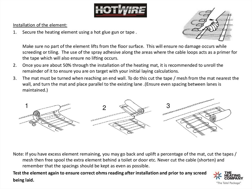
The mat must be turned when reaching an end wall. To do this cut the tape / mesh from the mat nearest the
wall, and turn the mat and place parallel to the existing lane .(Ensure even spacing between lanes is
maintained.)
1
2
3
Note: If you have excess element remaining, you may go back and uplift a percentage of the mat, cut the tapes /
mesh then free spool the extra element behind a toilet or door etc. Never cut the cable (shorten) and
remember that the spacings should be kept as even as possible.
Test the element again to ensure correct ohms reading after installation and prior to any screed
being laid.
7.
Floor probe (Sensor) & Cold Tails:1. Recess the probe flat onto the floor exactly between 2 runs of element.
This is to ensure that it obtains the correct temperature readings. Use hot
glue to hold it in place.
2. The probe wire must NOT cross over the heating element.
3. Ensure that there is enough probe wire to go up to the controller with the
cold tails.
4. Attach a draw wire to the ends of both cold tails as well as the floor probe
wire.
5. Gently pull up inside the wall so that the cold tails and probe wire can
reach the flush box.
6. NEVER allow the heating element to be within the wall cavity – only the
cold tails
7. Tape the cold tails to the flush box to avoid them dropping back down
inside the wall.
8. Test the continuity monitor is working (if supplied). Then attach to the 2
cold tails of the element as per the instructions. This will ensure that any
subsequent work on the floor will be monitored for damage.
9. Prior to tiling AVOID ANY UNNECESSARY foot traffic on the element .
10. If the floor is not being tiled /screeded immediately, a sheet of cardboard
should be laid over the element as an interim measure.
8.
Do’s and Don’ts:Do’s:
1.
2.
3.
4.
5.
6.
7.
8.
Read the installation instructions prior to the installation.
Ensure the surface is clean and clear of obstructions
Plan the heat mat layout prior to installation.
Pre-plan post drilling Eg: doorstops vanities etc to eliminate damage to the element.
Before starting and after laying use a multi-metre to check the resistance on the cable ensuring there is a circuit.
Ensure that all heating element is positioned on the floor and not up into the wall cavity.
Protect the element prior to tilling
Check the element again for resistance readings prior to tiling starting and when tiling be very carful not to damage the
element.
9. Use Tile adhesives and grouts that are suitable for use with underfloor heating.
10. Ensure that each tile is solidly bedded in adhesive with no air gaps.
11. If you are unsure of any aspect of the installation or the suitability of the subfloor to be heated, check with your supplier
(place of purchase) or call 0800 HEATING for technical advise.
Don’ts:
1.
2.
3.
4.
5.
6.
Don’t cut or attempt to shorten the element
Don’t commence installation on concrete floors that are not fully cured
Don’t allow the heating element to cross over or touch – nor cross over into another room.
Don’t allow the element to be installed on irregular surfaces.
Don’t commence tiling before checking the continuity tester is working and that it is fitted to the elements cold tails.
Don’t turn on the heating until the adhesives has fully cured (7 days)
9.
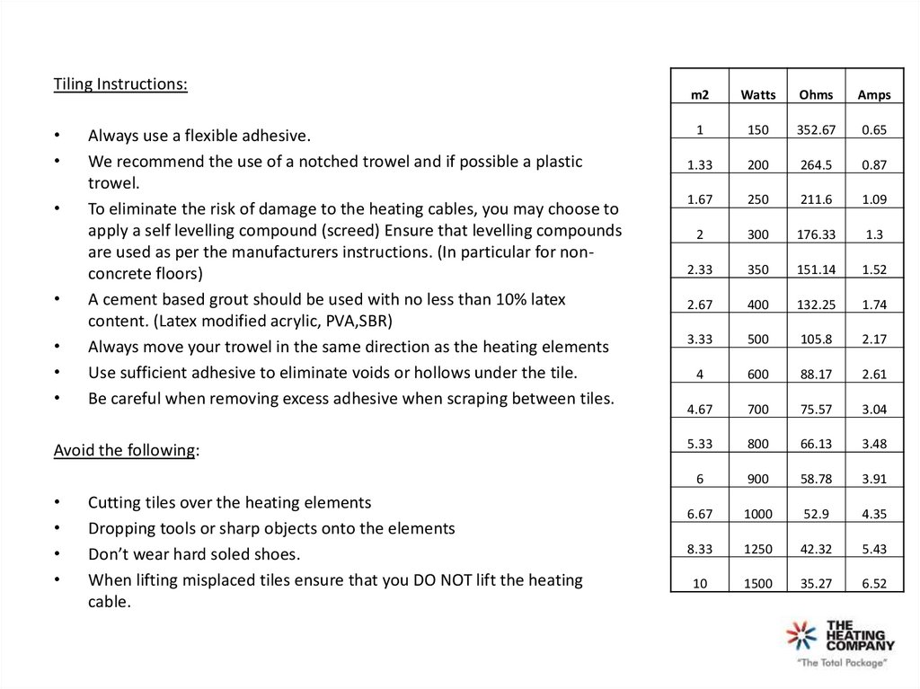
Tiling Instructions:Always use a flexible adhesive.
We recommend the use of a notched trowel and if possible a plastic
trowel.
To eliminate the risk of damage to the heating cables, you may choose to
apply a self levelling compound (screed) Ensure that levelling compounds
are used as per the manufacturers instructions. (In particular for nonconcrete floors)
A cement based grout should be used with no less than 10% latex
content. (Latex modified acrylic, PVA,SBR)
Always move your trowel in the same direction as the heating elements
Use sufficient adhesive to eliminate voids or hollows under the tile.
Be careful when removing excess adhesive when scraping between tiles.
Avoid the following:
Cutting tiles over the heating elements
Dropping tools or sharp objects onto the elements
Don’t wear hard soled shoes.
When lifting misplaced tiles ensure that you DO NOT lift the heating
cable.
m2
Watts
Ohms
Amps
1
150
352.67
0.65
1.33
200
264.5
0.87
1.67
250
211.6
1.09
2
300
176.33
1.3
2.33
350
151.14
1.52
2.67
400
132.25
1.74
3.33
500
105.8
2.17
4
600
88.17
2.61
4.67
700
75.57
3.04
5.33
800
66.13
3.48
6
900
58.78
3.91
6.67
1000
52.9
4.35
8.33
1250
42.32
5.43
10
1500
35.27
6.52
10.
Register Your Full Product Warranty on line http://www.theheatingcompany.co.nzPh: +64 9 443 6996 Fax:+64 9 929 3322
149-151 Sunnybrae Road | Glenfield | Auckland | 0627 New Zealand