


 industry
Similar presentations:


Hermes10 A과제-PJT
1.
SAMSUNG Side by Side RefrigeratorHERMES10 A과제-PJT
TRAINING MANUAL
BASIC : RSH5ZEPN
MODEL NAME (MODEL CODE) : RSH5****
RSH5***
Mar. 2010
Refrigerator Division
2.
CONTENTS1. Product Introduction
2. Instruction of Function
3. Alignment & Adjustment
4. Disassembly & Reassembly
5. SELF DIAGNOSIS & TROUBLE SHOOTING
6. Block diagram
7. PCB diagram
8. Wiring diagram
9. Reference Information
3.
1.Product Introduction1-1. Charcteristics
Comparison with basic
Changed Part
Door
H o m eBar
Door
D isp lay
Insert
D escrip tio n
N ew desig n
Soft to u ch typ e H o m e Bar
N ew desig n D isp lay
Co nvertib le N ew desig n Co nvertib le
Basic
Current
4.
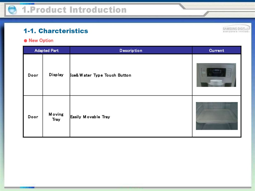
1.Product Introduction1-1. Charcteristics
New Option
Adapted Part
D escrip tio n
Door
D isp lay
Ice& W ater Typ e To u ch Bu tto n
Door
M o ving
Tray
Easily M o vab le Tray
Current
5.
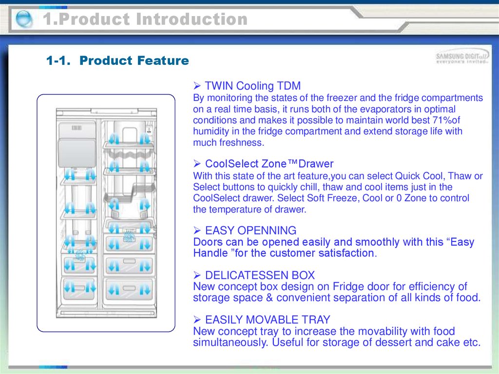
1.Product Introduction1-1. Product Feature
TWIN Cooling TDM
By monitoring the states of the freezer and the fridge compartments
on a real time basis, it runs both of the evaporators in optimal
conditions and makes it possible to maintain world best 71%of
humidity in the fridge compartment and extend storage life with
much freshness.
CoolSelect Zone™Drawer
With this state of the art feature,you can select Quick Cool, Thaw or
Select buttons to quickly chill, thaw and cool items just in the
CoolSelect drawer. Select Soft Freeze, Cool or 0 Zone to control
the temperature of drawer.
EASY OPENNING
Doors can be opened easily and smoothly with this “Easy
Handle ”for the customer satisfaction.
DELICATESSEN BOX
New concept box design on Fridge door for efficiency of
storage space & convenient separation of all kinds of food.
EASILY MOVABLE TRAY
New concept tray to increase the movability with food
simultaneously. Useful for storage of dessert and cake etc.
6.
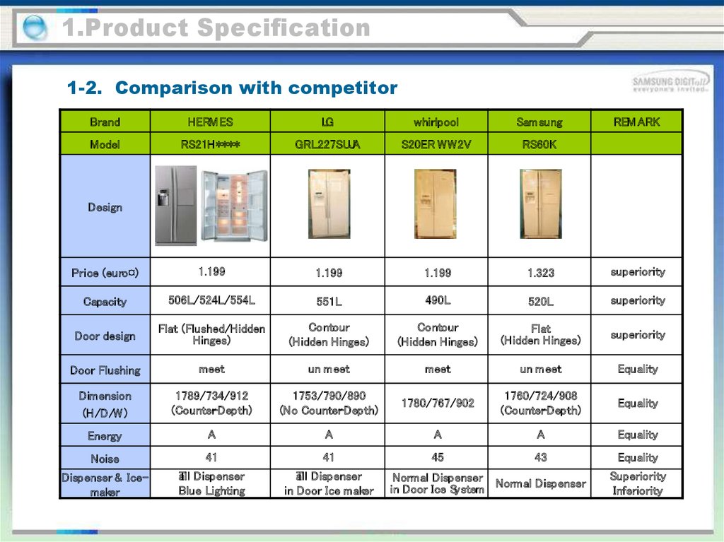
1.Product Specification1-2. Comparison with competitor
Brand
HERM ES
LG
whirlpool
Sam sung
REM ARK
Model
RS21H****
GRL227SUJA
S20ER WW2V
RS60K
Price (euro¤)
1.199
1.199
1.199
1.323
superiority
Capacity
506L/524L/554L
551L
490L
520L
superiority
Door design
Flat (Flushed/Hidden
Hinges)
Contour
(Hidden Hinges)
Contour
(Hidden Hinges)
Flat
(Hidden Hinges)
superiority
Door Flushing
meet
un meet
meet
un meet
Equality
Dimension
(H/D/W )
1789/734/912
(Counter-Depth)
1753/790/890
(No Counter-Depth)
1780/767/902
1760/724/908
(Counter-Depth)
Equality
Energy
A
A
A
A
Equality
Noise
41
41
45
43
Equality
Dispenser & Icemaker
aTll Dispenser
Blue Lighting
aTll Dispenser
in Door Ice maker
Design
Normal Dispenser
in Door Ice System Normal Dispenser
Superiority
Inferiority
7.
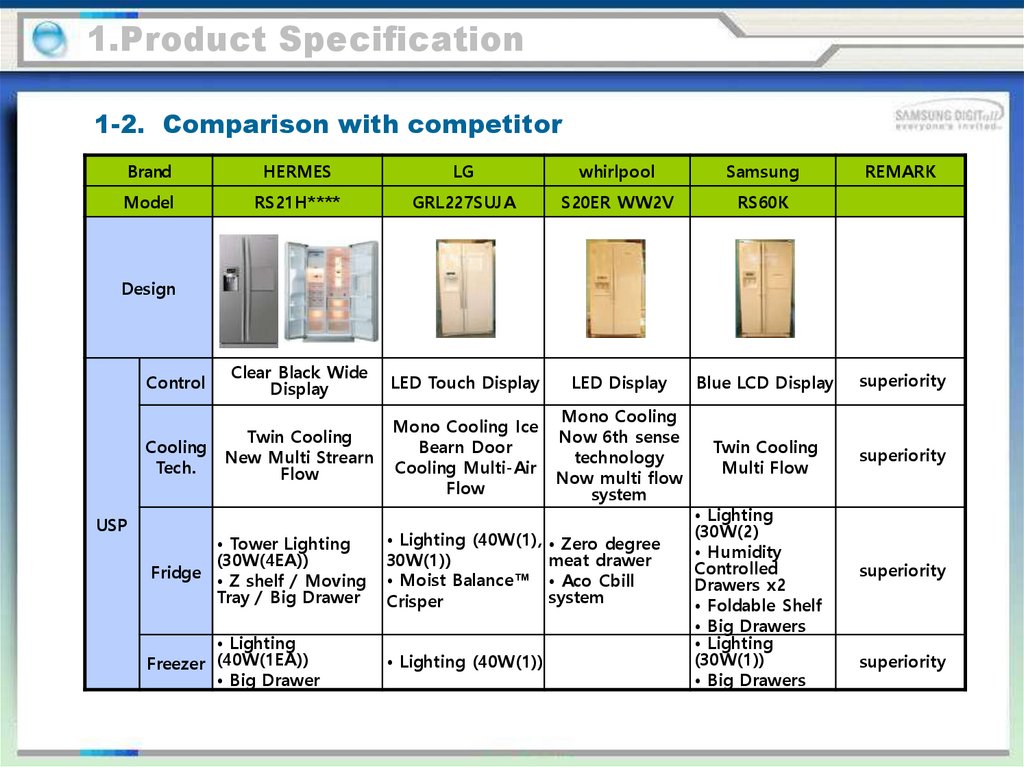
1.Product Specification1-2. Comparison with competitor
Brand
HERMES
LG
whirlpool
Samsung
REMARK
Model
RS21H****
GRL227SUJA
S20ER WW2V
RS60K
Control
Clear Black Wide
Display
LED Touch Display
LED Display
Blue LCD Display
superiority
Cooling
Tech.
Twin Cooling
New Multi Strearn
Flow
Mono Cooling Ice
Bearn Door
Cooling Multi-Air
Flow
Mono Cooling
Now 6th sense
technology
Now multi flow
system
Twin Cooling
Multi Flow
superiority
Design
USP
• Tower Lighting
(30W(4EA))
Fridge • Z shelf / Moving
Tray / Big Drawer
• Lighting (40W(1),
30W(1))
• Moist Balance™
Crisper
• Lighting
Freezer (40W(1EA))
• Big Drawer
• Lighting (40W(1))
• Zero degree
meat drawer
• Aco Cbill
system
• Lighting
(30W(2)
• Humidity
Controlled
Drawers x2
• Foldable Shelf
• Big Drawers
• Lighting
(30W(1))
• Big Drawers
superiority
superiority
8.
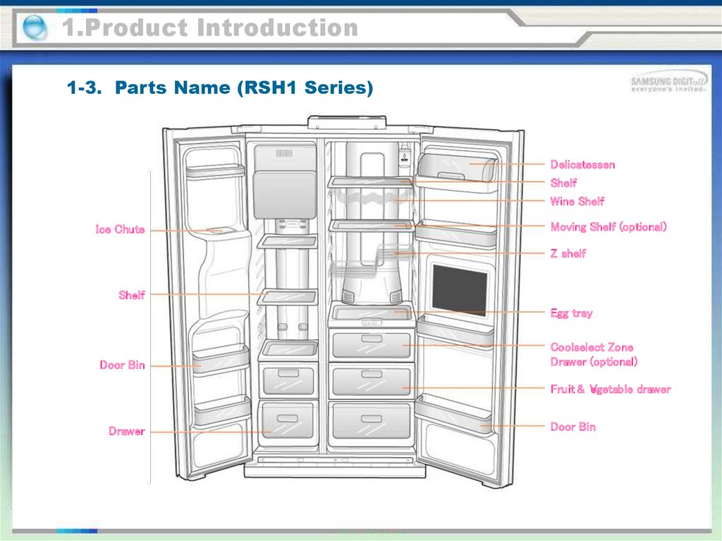
1.Product Introduction1-3. Parts Name (RSJ1 Series)
Delicatessen
Shelf
Wine Shelf
Ice Chute
Moving Shelf (optional)
Z shelf
Shelf
Egg tray
Door Bin
Coolselect Zone
Drawer (optional)
Fruit & V
egetable drawer
Drawer
Door Bin
9.
1.Product Introduction1-3. Parts Name (RSH1 Series)
Delicatessen
Shelf
Wine Shelf
Ice Chute
Moving Shelf (optional)
Z shelf
Shelf
Egg tray
Door Bin
Coolselect Zone
Drawer (optional)
Fruit & V
egetable drawer
Drawer
Door Bin
10.
1.Product Introduction1-4. Specification (RSH5 Series)
Item
Specification
Z/K
Y/J
P/F
U/D
V/B
Disp+H/B+ Dispenser+
Dispenser+
Cool select Cool select
Dispenser Home Bar
Home Bar
zone
zone
Model
Defrost- Heater(FRE)
Defrost-Heater(REF)
Components for Freezer
Conducting at F
Defrosting
Conducting at R
Defrosting
DISPEN SER HEA
TER
Interlock with F-FAN
HOME-BAR HEA
TER
Interlock with COM P
WA
TER PIPE HEA
TER
-
WA
TER PIPE HEA
TER
-
Bimetal for preventing overheating of Freezer
Defrost-Heater
Bimetal for preventing overheating of Refrigerator
Defrost-Heater
Condenser for
Running
COM PRESSOR (Package
Star ting
type)
S/N
Basic
Sheath Heater 230V 230W
Sheath Heater 230V 140W
AC230V
5W
AC230V
7W
AC230V
10W
AC230V
5W
AC230V
5W
AC230V
10W
AC230V
5W
AC230V
5W
AC230V
7W
AC230V
10W
AC230V
5W
AC230V
5W
-
-
-
AC230V
7W
-
-
-
-
-
AC230V
10W
AC230V
5W
Bimetal thermostat(BT-121-M )
On: 40°C Off : 60°C
Thermo-Fuse (Cutoff : 110°C)
Inver ter : NO R600a: 450VAC/5.0㎌ R134a: 450VAC/5.0㎌
-
11.
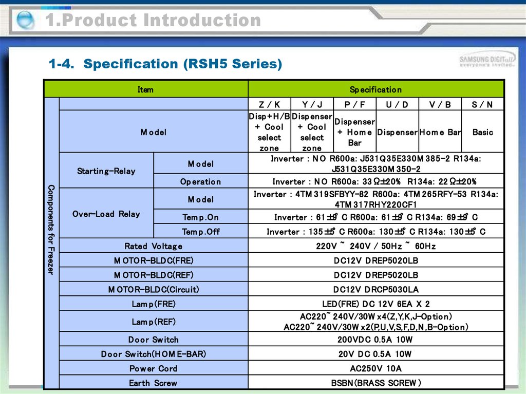
1.Product Introduction1-4. Specification (RSH5 Series)
Item
Sp ecificatio n
M o del
M o del
Startin g-Relay
Components for Freezer
Op eratio n
M o del
Over-Load Relay
Tem p .On
Tem p .Off
Z/K
Y/J
P/F
U/D
V/B
S/N
D isp + H /B D isp enser
D isp enser
+ Co o l
+ Co o l
+ H o m e D isp enser H o m e Bar Basic
select
select
Bar
zo ne
zo ne
Inverter : N O R600a: J531Q35E330M 385-2 R134a:
J531Q35E330M 350-2
Inverter : N O R600a: 33Ω±20% R134a: 22Ω±20%
Inverter : 4TM 319SFBYY-82 R600a: 4TM 265RFY-53 R134a:
4TM 317RH Y220CF1
Inverter : 61±9°C R600a: 61±9°C R134a: 69±9°C
Inverter : 135±5°C R600a: 130±5°C R134a: 130±5°C
Rated Vo ltag e
220V ~ 240V / 50H z ~ 60H z
M OTOR-BLDC(FRE)
D C12V D REP5020LB
M OTOR-BLDC(REF)
D C12V D REP5020LB
M OTOR-BLDC(Circu it)
D C12V D RCP5030LA
Lam p (FRE)
D o o r Sw itch
LED (FRE) D C 12V 6EA X 2
AC220~ 240V/30W x4(Z,Y,K,J-Op tio n)
AC220~ 240V/30W x2(P,U,V,S,F,D,N ,B-Op tio n)
200VD C 0.5A 10W
D o o r Sw itch(H OM E-BAR)
20V D C 0.5A 10W
Po w er Co rd
AC250V 10A
Earth Screw
BSBN (BRASS SCREW )
Lam p (REF)
12.
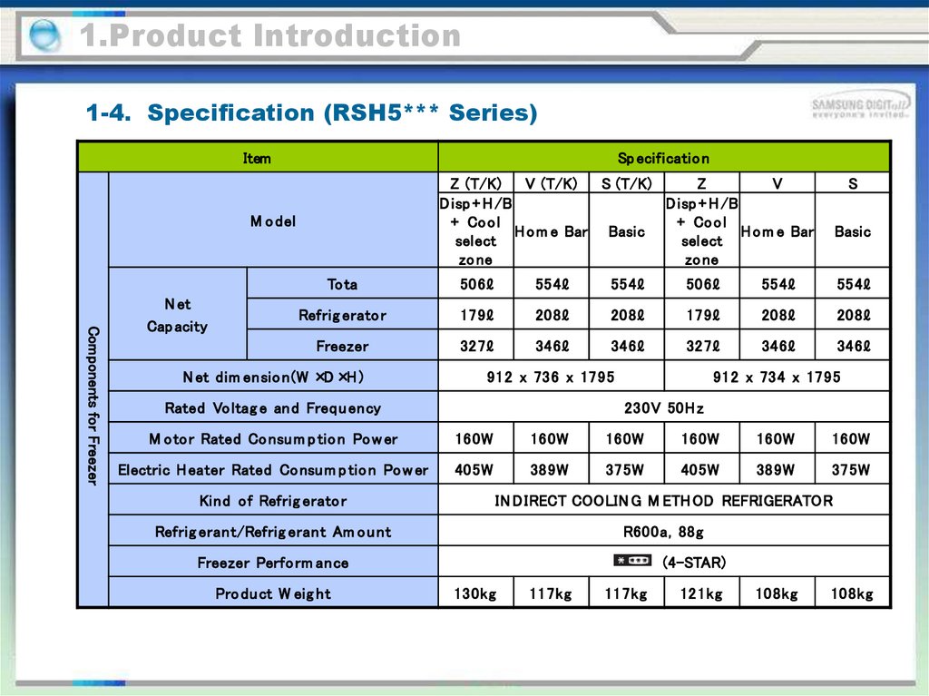
1.Product Introduction1-4. Specification (RSH5*** Series)
Item
Sp ecificatio n
Z (T/K)
V (T/K)
S (T/K)
Z
V
D isp + H /B
D isp + H /B
+ Co o l
+ Co o l
H o m e Bar Basic
H o m e Bar
select
select
zo ne
zo ne
M o del
Components for Freezer
N et
Cap acity
S
Basic
To ta
506ℓ
554ℓ
554ℓ
506ℓ
554ℓ
554ℓ
Refrig erato r
179ℓ
208ℓ
208ℓ
179ℓ
208ℓ
208ℓ
Freezer
327ℓ
346ℓ
346ℓ
327ℓ
346ℓ
346ℓ
N et dim ensio n(W ×D ×H )
912 x 736 x 1795
Rated Vo ltag e an d Freq u ency
912 x 734 x 1795
230V 50H z
M o to r Rated Co nsu m p tio n Po w er
160W
160W
160W
160W
160W
160W
Electric H eater Rated Co nsu m p tio n Po w er
405W
389W
375W
405W
389W
375W
Kind of Refrig erato r
IN D IRECT COOLIN G M ETH OD REFRIGERATOR
Refrig erant/Refrig erant Am o u nt
R600a, 88g
Freezer Perfo rm ance
Pro du ct W eig ht
(4-STAR)
130kg
117kg
117kg
121kg
108kg
108kg
13.
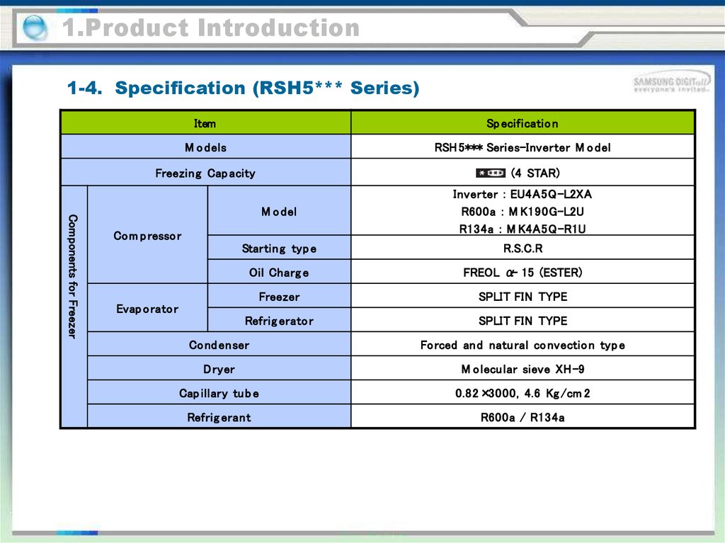
1.Product Introduction1-4. Specification (RSH5*** Series)
Item
Sp ecificatio n
M o dels
RSH 5*** Series-Inverter M o del
Freezing Cap acity
(4 STAR)
Components for Freezer
M o del
Inverter : EU4A5Q-L2XA
R600a : M K190G-L2U
R134a : M K4A5Q-R1U
Startin g typ e
R.S.C.R
Oil Charg e
FREOL α- 15 (ESTER)
Freezer
SPLIT FIN TYPE
Refrig erato r
SPLIT FIN TYPE
Co m p resso r
Evap o rato r
Co nd enser
Fo rced and natu ral co nvectio n typ e
D ryer
M o lecu lar sieve XH -9
Cap illary tu b e
0.82×3000, 4.6 Kg /cm 2
Refrig erant
R600a / R134a
14.
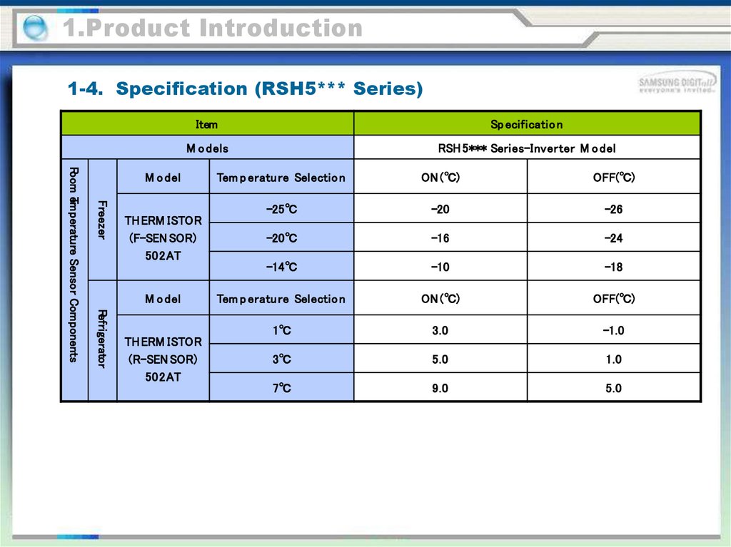
1.Product Introduction1-4. Specification (RSH5*** Series)
Item
Sp ecificatio n
M o dels
RSH 5*** Series-Inverter M o del
Freezer
TH ERM ISTOR
(F-SEN SOR)
502AT
M o del
Refrigerator
Room eTmperature Sensor Components
M o del
TH ERM ISTOR
(R-SEN SOR)
502AT
Tem p eratu re Selectio n
ON (℃)
OFF(℃)
-25℃
-20
-26
-20℃
-16
-24
-14℃
-10
-18
Tem p eratu re Selectio n
ON (℃)
OFF(℃)
1℃
3.0
-1.0
3℃
5.0
1.0
7℃
9.0
5.0
15.
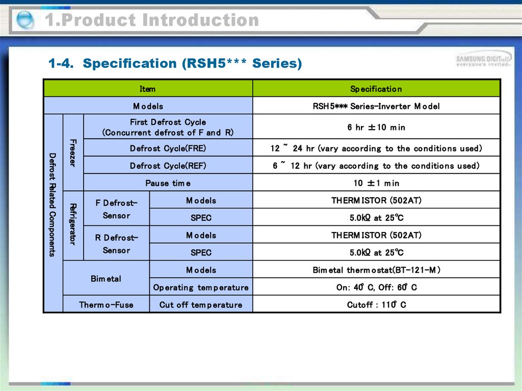
1.Product Introduction1-4. Specification (RSH5*** Series)
Item
Sp ecificatio n
M o dels
RSH 5*** Series-Inverter M o del
6 hr ±10 m in
D efro st Cycle(FRE)
12 ~ 24 hr (vary acco rd ing to the co nd itio ns u sed )
D efro st Cycle(REF)
6 ~ 12 hr (vary acco rd in g to the co nd itio ns u sed )
Pau se tim e
10 ±1 m in
Freezer
Refrigerator
Defrost Related Components
First D efro st Cycle
(Co ncu rrent defro st of F an d R)
F D efro stSenso r
M o dels
TH ERM ISTOR (502AT)
SPEC
5.0㏀ at 25℃
R D efro stSenso r
M o dels
TH ERM ISTOR (502AT)
SPEC
5.0㏀ at 25℃
M o dels
Bim etal therm o stat(BT-121-M )
Op eratin g tem p eratu re
On : 40°C, Off : 60°C
Cut off tem p eratu re
Cutoff : 110°C
Bim etal
Therm o -Fuse
16.
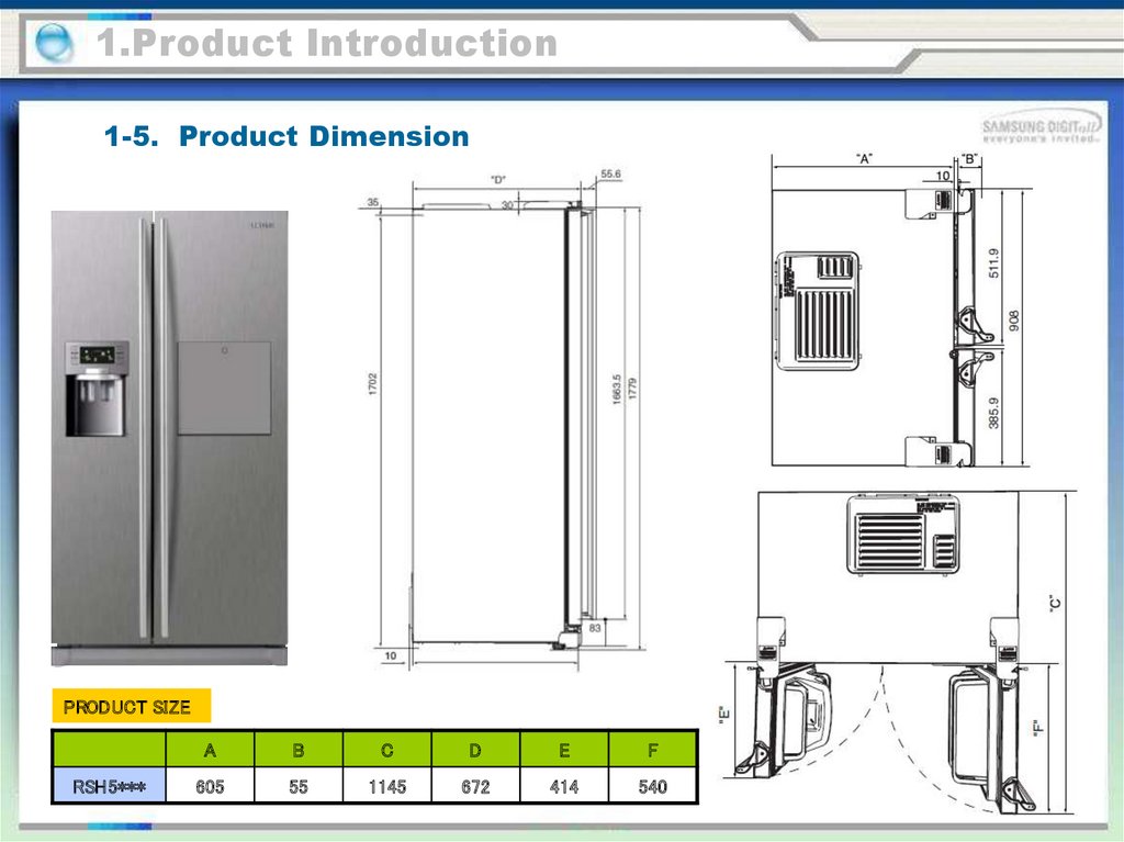
1.Product Introduction1-5. Product Dimension
PRODUCT SIZE
RSH5***
A
B
C
D
E
F
605
55
1145
672
414
540
17.
1.Product Introduction1-6. Refrigeration TDM Cycle
Compressor
SPIRAL-CONDENSER
FRIDGE HOT PIPE
Fridge Capillar y uTbe
Fridge Evaporator
Dr yer
3WA
Y VALVE
CONNECTED CAPILL ARY
Freezer Capillar y uTbe
ACCUM UL A
TOR
Compressor
Freezer Evaporator
SUCTION PIPE
18.
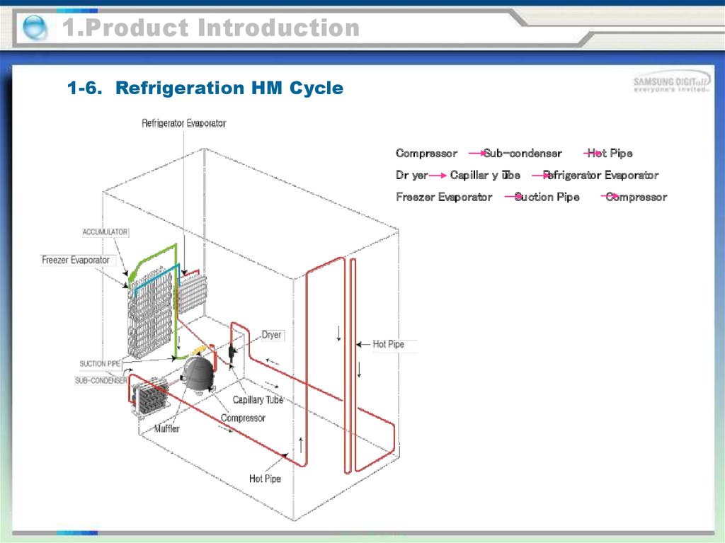
1.Product Introduction1-6. Refrigeration HM Cycle
Compressor
Dr yer
Sub-condenser
Capillar y uTbe
Freezer Evaporator
Hot Pipe
Refrigerator Evaporator
Suction Pipe
Compressor
19.
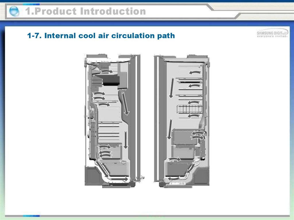
1.Product Introduction1-7. Internal cool air circulation path
20.
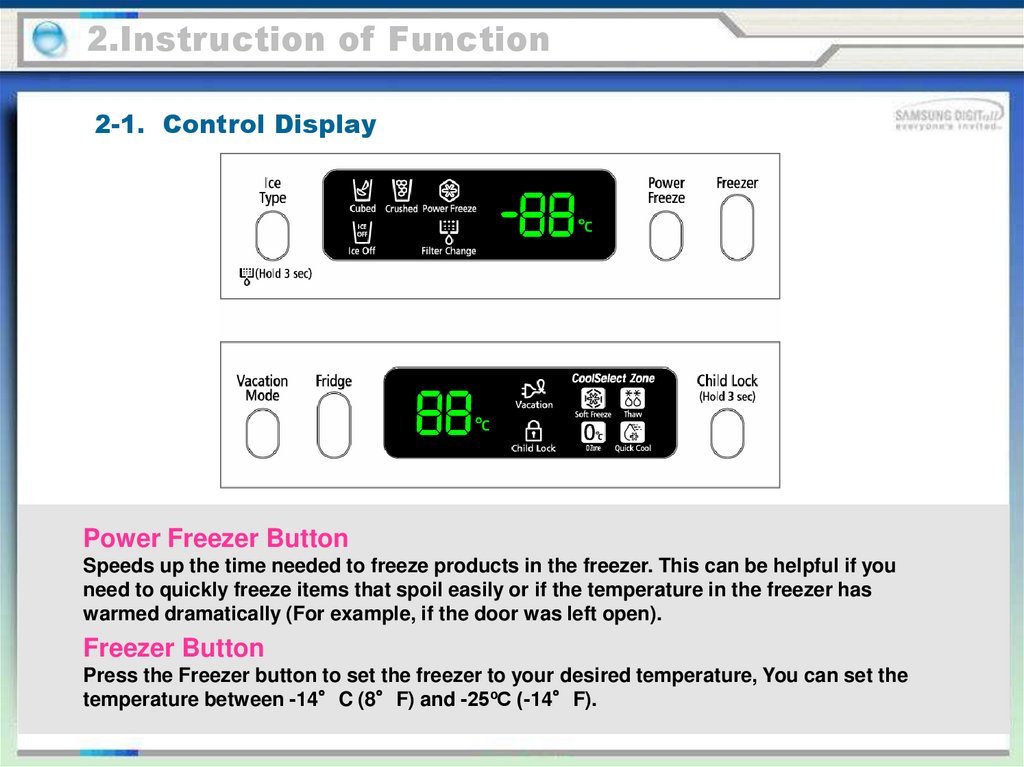
2.Instruction of Function2-1. Control Display
Power Freezer Button
Speeds up the time needed to freeze products in the freezer. This can be helpful if you
need to quickly freeze items that spoil easily or if the temperature in the freezer has
warmed dramatically (For example, if the door was left open).
Freezer Button
Press the Freezer button to set the freezer to your desired temperature, You can set the
temperature between -14°C (8°F) and -25ºC (-14°F).
21.
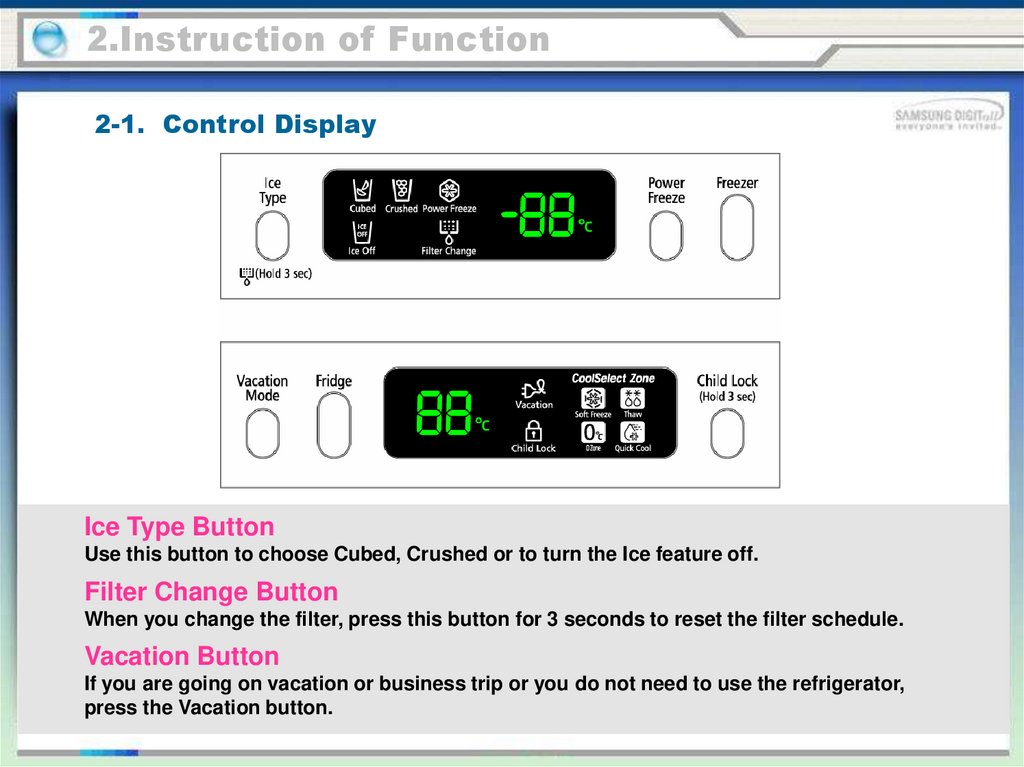
2.Instruction of Function2-1. Control Display
Ice Type Button
Use this button to choose Cubed, Crushed or to turn the Ice feature off.
Filter Change Button
When you change the filter, press this button for 3 seconds to reset the filter schedule.
Vacation Button
If you are going on vacation or business trip or you do not need to use the refrigerator,
press the Vacation button.
22.
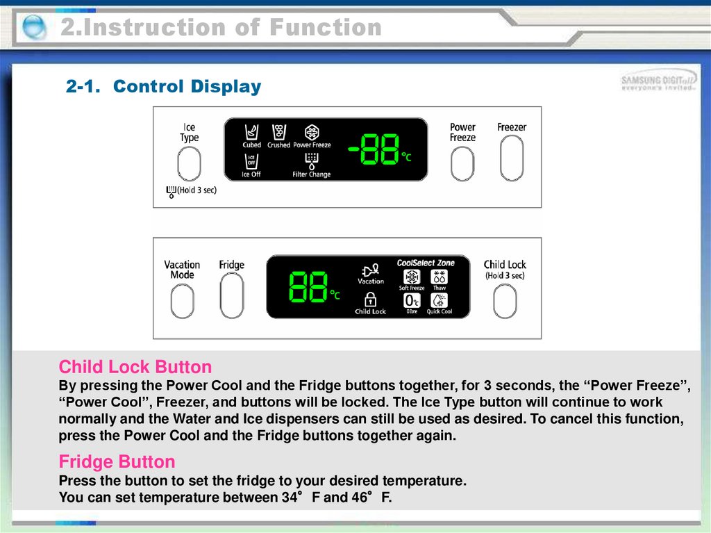
2.Instruction of Function2-1. Control Display
Child Lock Button
By pressing the Power Cool and the Fridge buttons together, for 3 seconds, the “Power Freeze”,
“Power Cool”, Freezer, and buttons will be locked. The Ice Type button will continue to work
normally and the Water and Ice dispensers can still be used as desired. To cancel this function,
press the Power Cool and the Fridge buttons together again.
Fridge Button
Press the button to set the fridge to your desired temperature.
You can set temperature between 34°F and 46°F.
23.
2.Instruction of Function2-2. FRESH SELECT ZONE™ DRAWER GUIDE
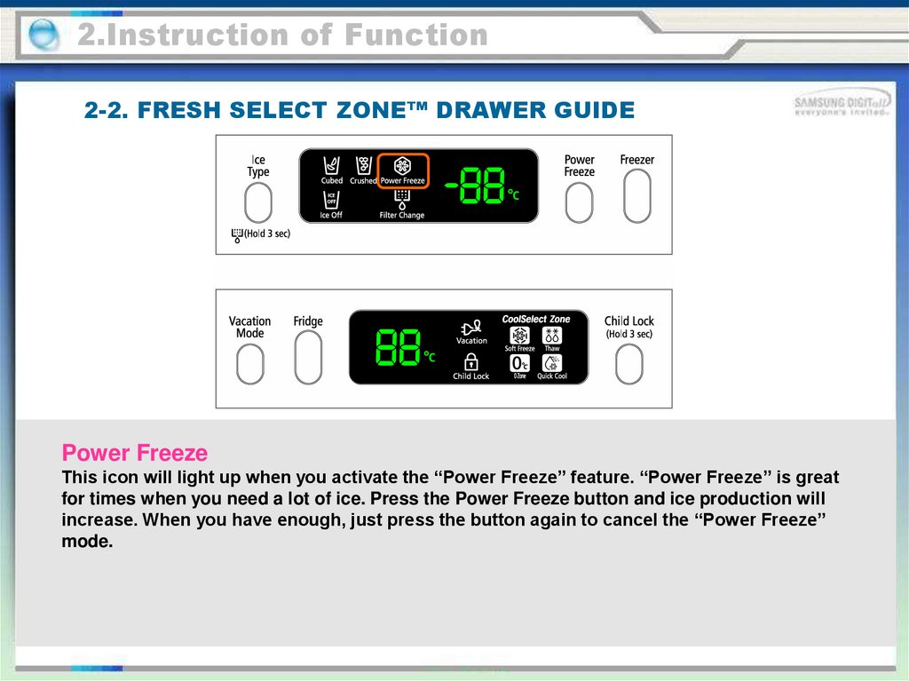
Power Freeze
This icon will light up when you activate the “Power Freeze” feature. “Power Freeze” is great
for times when you need a lot of ice. Press the Power Freeze button and ice production will
increase. When you have enough, just press the button again to cancel the “Power Freeze”
mode.
24.
2.Instruction of Function2-2. FRESH SELECT ZONE™ DRAWER GUIDE
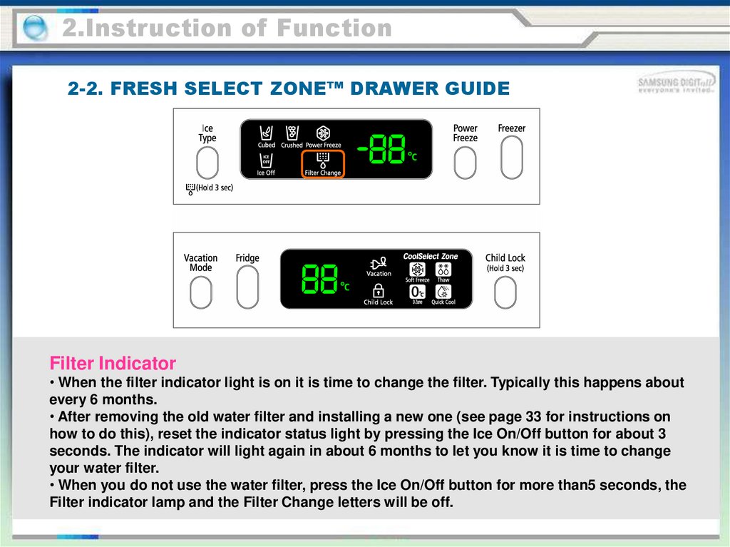
Filter Indicator
• When the filter indicator light is on it is time to change the filter. Typically this happens about
every 6 months.
• After removing the old water filter and installing a new one (see page 33 for instructions on
how to do this), reset the indicator status light by pressing the Ice On/Off button for about 3
seconds. The indicator will light again in about 6 months to let you know it is time to change
your water filter.
• When you do not use the water filter, press the Ice On/Off button for more than5 seconds, the
Filter indicator lamp and the Filter Change letters will be off.
25.
2.Instruction of Function2-2. FRESH SELECT ZONE™ DRAWER GUIDE
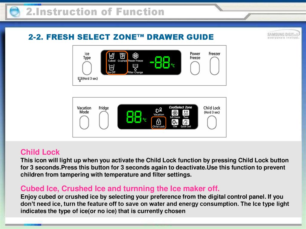
Child Lock
This icon will light up when you activate the Child Lock function by pressing Child Lock button
for 3 seconds.Press this button for 3 seconds again to deactivate.Use this function to prevent
children from tampering with temperature and filter settings.
Cubed Ice, Crushed Ice and turnning the Ice maker off.
Enjoy cubed or crushed ice by selecting your preference from the digital control panel. If you
don’t need ice, turn the feature off to save on water and energy consumption. The Ice type light
indicates the type of ice(or no ice) that is currently chosen
26.
2.Instruction of Function2-3. Ice Maker Function
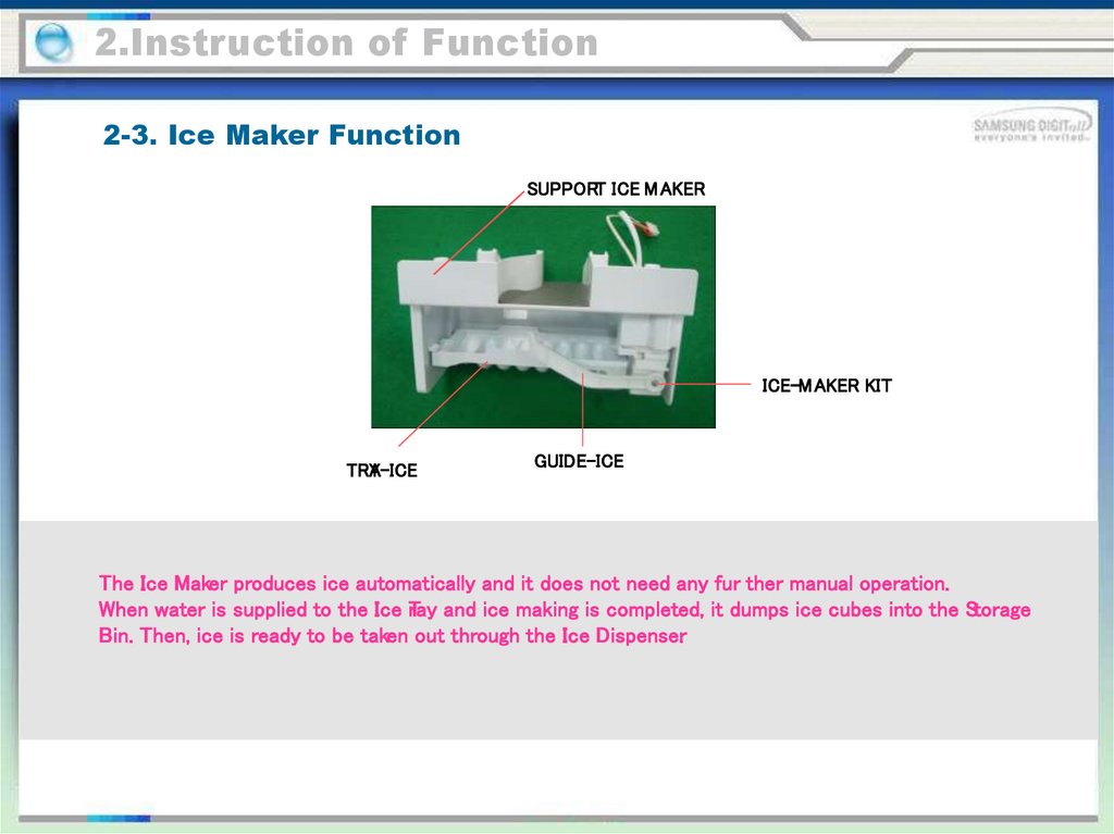
SUPPORT ICE M AKER
ICE-M AKER KIT
TRA
Y-ICE
GUIDE-ICE
The Ice Maker produces ice automatically and it does not need any fur ther manual operation.
When water is supplied to the Ice T
ray and ice making is completed, it dumps ice cubes into the Storage
Bin. Then, ice is ready to be taken out through the Ice Dispenser.
27.
2.Instruction of Function2-3. Ice Maker Function
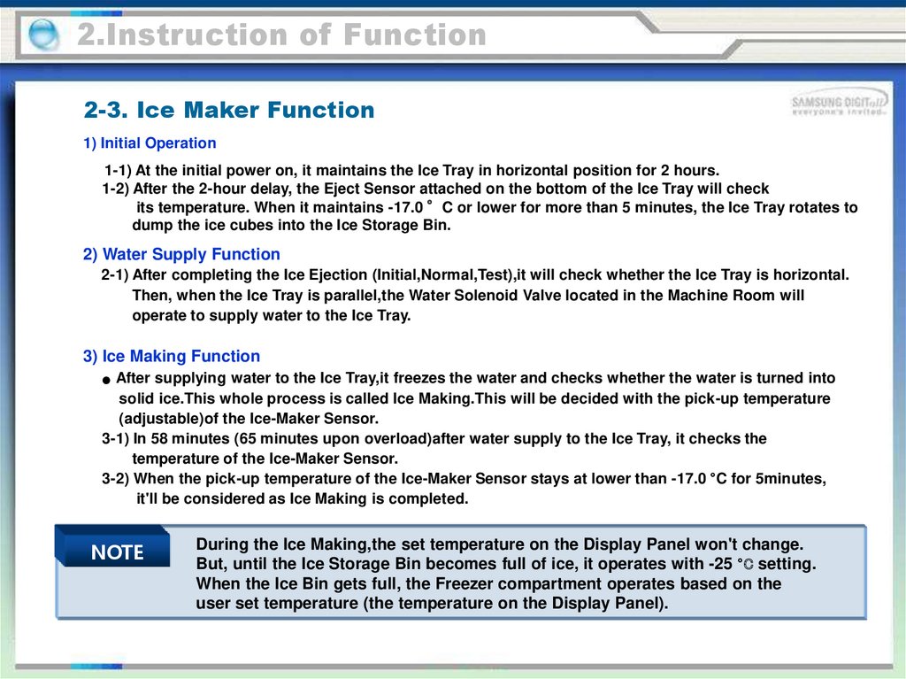
1) Initial Operation
1-1) At the initial power on, it maintains the Ice Tray in horizontal position for 2 hours.
1-2) After the 2-hour delay, the Eject Sensor attached on the bottom of the Ice Tray will check
its temperature. When it maintains -17.0 °C or lower for more than 5 minutes, the Ice Tray rotates to
dump the ice cubes into the Ice Storage Bin.
2) Water Supply Function
2-1) After completing the Ice Ejection (Initial,Normal,Test),it will check whether the Ice Tray is horizontal.
Then, when the Ice Tray is parallel,the Water Solenoid Valve located in the Machine Room will
operate to supply water to the Ice Tray.
3) Ice Making Function
After supplying water to the Ice Tray,it freezes the water and checks whether the water is turned into
solid ice.This whole process is called Ice Making.This will be decided with the pick-up temperature
(adjustable)of the Ice-Maker Sensor.
3-1) In 58 minutes (65 minutes upon overload)after water supply to the Ice Tray, it checks the
temperature of the Ice-Maker Sensor.
3-2) When the pick-up temperature of the Ice-Maker Sensor stays at lower than -17.0 °C for 5minutes,
it'll be considered as Ice Making is completed.
NOTE
During the Ice Making,the set temperature on the Display Panel won't change.
But, until the Ice Storage Bin becomes full of ice, it operates with -25 °C setting.
When the Ice Bin gets full, the Freezer compartment operates based on the
user set temperature (the temperature on the Display Panel).
28.
2.Instruction of Function2-3. Ice Maker Function
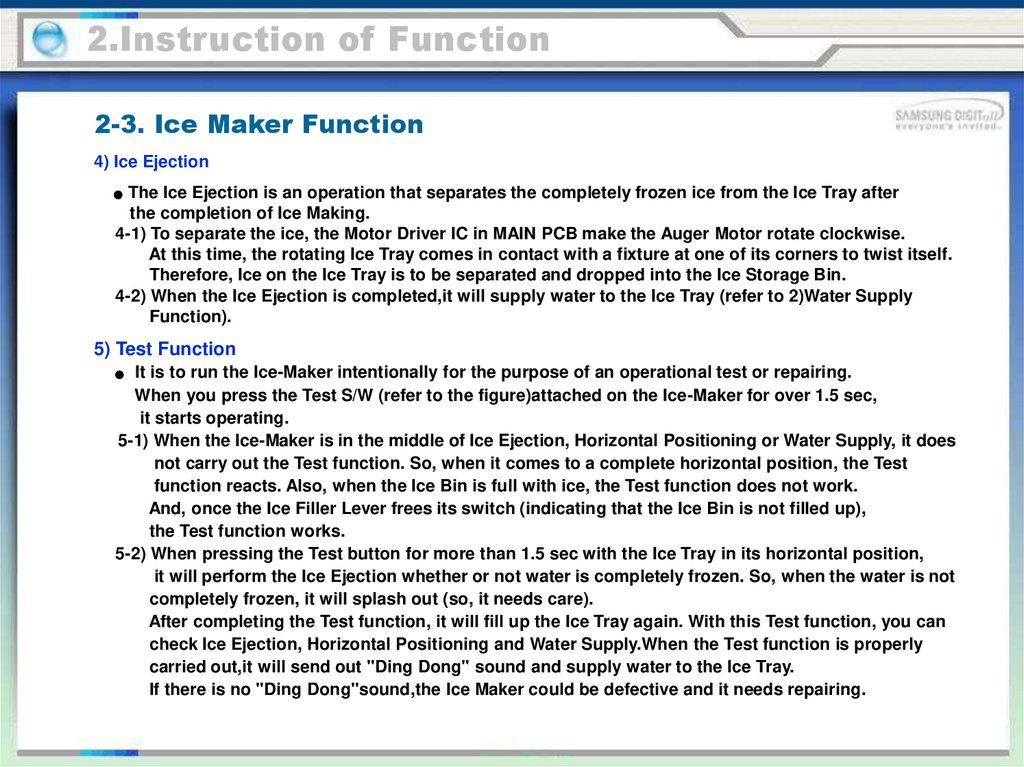
4) Ice Ejection
The Ice Ejection is an operation that separates the completely frozen ice from the Ice Tray after
the completion of Ice Making.
4-1) To separate the ice, the Motor Driver IC in MAIN PCB make the Auger Motor rotate clockwise.
At this time, the rotating Ice Tray comes in contact with a fixture at one of its corners to twist itself.
Therefore, Ice on the Ice Tray is to be separated and dropped into the Ice Storage Bin.
4-2) When the Ice Ejection is completed,it will supply water to the Ice Tray (refer to 2)Water Supply
Function).
5) Test Function
It is to run the Ice-Maker intentionally for the purpose of an operational test or repairing.
When you press the Test S/W (refer to the figure)attached on the Ice-Maker for over 1.5 sec,
it starts operating.
5-1) When the Ice-Maker is in the middle of Ice Ejection, Horizontal Positioning or Water Supply, it does
not carry out the Test function. So, when it comes to a complete horizontal position, the Test
function reacts. Also, when the Ice Bin is full with ice, the Test function does not work.
And, once the Ice Filler Lever frees its switch (indicating that the Ice Bin is not filled up),
the Test function works.
5-2) When pressing the Test button for more than 1.5 sec with the Ice Tray in its horizontal position,
it will perform the Ice Ejection whether or not water is completely frozen. So, when the water is not
completely frozen, it will splash out (so, it needs care).
After completing the Test function, it will fill up the Ice Tray again. With this Test function, you can
check Ice Ejection, Horizontal Positioning and Water Supply.When the Test function is properly
carried out,it will send out "Ding Dong" sound and supply water to the Ice Tray.
If there is no "Ding Dong"sound,the Ice Maker could be defective and it needs repairing.
29.
2.Instruction of Function2-3. Ice Maker Function
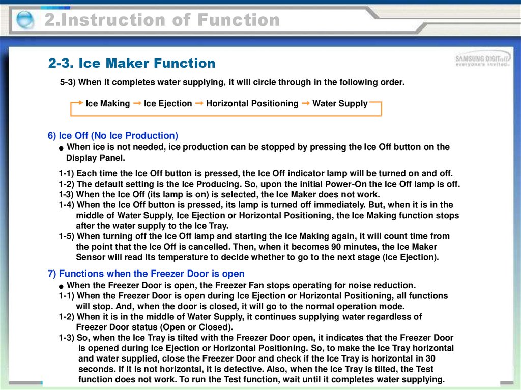
5-3) When it completes water supplying, it will circle through in the following order.
Ice Making ➞ Ice Ejection ➞ Horizontal Positioning ➞ Water Supply
6) Ice Off (No Ice Production)
When ice is not needed, ice production can be stopped by pressing the Ice Off button on the
Display Panel.
1-1) Each time the Ice Off button is pressed, the Ice Off indicator lamp will be turned on and off.
1-2) The default setting is the Ice Producing. So, upon the initial Power-On the Ice Off lamp is off.
1-3) When the Ice Off (its lamp is on) is selected, the Ice Maker does not work.
1-4) When the Ice Off button is pressed, its lamp is turned off immediately. But, when it is in the
middle of Water Supply, Ice Ejection or Horizontal Positioning, the Ice Making function stops
after the water supply to the Ice Tray.
1-5) When turning off the Ice Off lamp and starting the Ice Making again, it will count time from
the point that the Ice Off is cancelled. Then, when it becomes 90 minutes, the Ice Maker
Sensor will read its temperature to decide whether to go to the next stage (Ice Ejection).
7) Functions when the Freezer Door is open
When the Freezer Door is open, the Freezer Fan stops operating for noise reduction.
1-1) When the Freezer Door is open during Ice Ejection or Horizontal Positioning, all functions
will stop. And, when the door is closed, it will go to the normal operation mode.
1-2) When it is in the middle of Water Supply, it continues supplying water regardless of
Freezer Door status (Open or Closed).
1-3) So, when the Ice Tray is tilted with the Freezer Door open, it indicates that the Freezer Door
is opened during Ice Ejection or Horizontal Positioning. So, to make the Ice Tray horizontal
and water supplied, close the Freezer Door and check if the Ice Tray is horizontal in 30
seconds. If it is not horizontal, it is defective. Also, when the Ice Tray is tilted, the Test
function does not work. To run the Test function, wait until it completes water supplying.
30.
2. Product function2-4. Defrost Function
1) Freezer and Fridge defrost will be determined by the total Comp-On time.
2) With the initial power on,the unit carries out Freezer and Fridge defrost when the total CompOn time becomes 6 hours.
3) The defrost cycle varies from 6 to 19 hours depending on its working conditions.
4) The defrost cycle is to be decided depending on the ambient temperature,the number of the
Freezer and Fridge door openings,and the duration of the Freezer and the Fridge door
openings.
5) The followings are the Defrost reset temperatures based on the Fridge defrost sensor ost and
the Freezer defrost sensor sensor temperatures.
Defrost Reset Temperature
NOTE
Fridge
Freezer
12°C
12°C
Remarks
The Defrost reset temperature can be changed without notice for functional imp
rovements.
31.
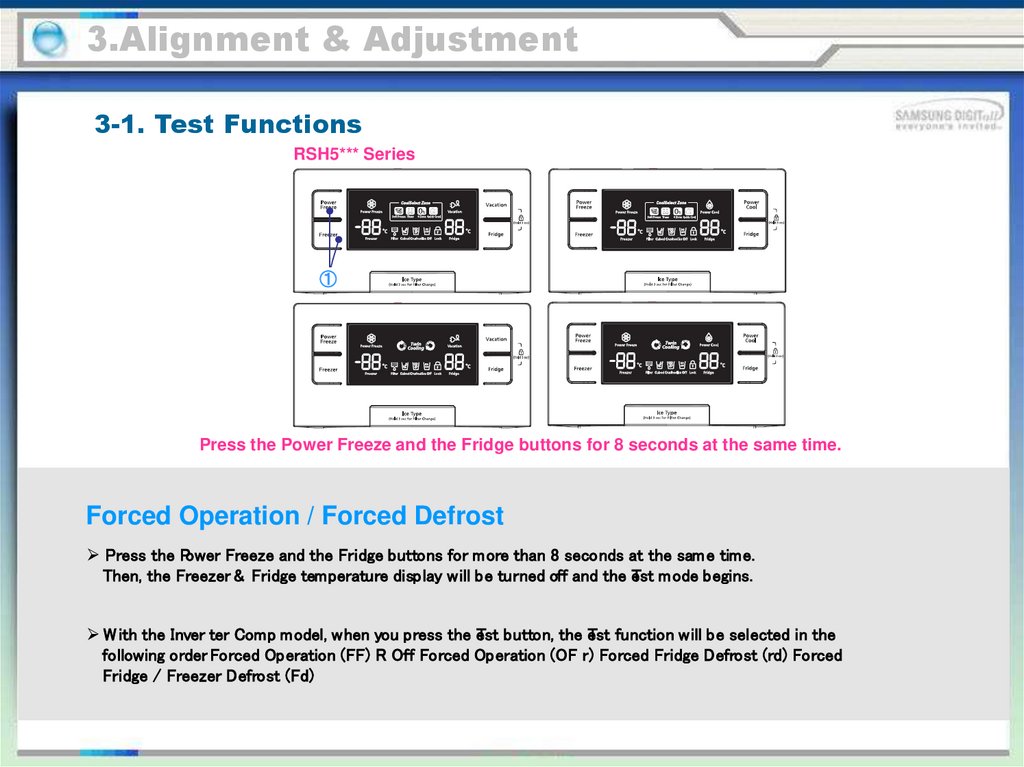
3.Alignment & Adjustment3-1. Test Functions
RSH5*** Series
①
Press the Power Freeze and the Fridge buttons for 8 seconds at the same time.
Forced Operation / Forced Defrost
Press the Power Freeze and the Fridge buttons for more than 8 seconds at the sam e time.
Then, the Freezer & Fridge temperature display will be turned off and the eTst mode begins.
W ith the Inver ter Comp model, when you press the eTst button, the eTst function will be selected in the
following order. Forced Operation (FF) R Off Forced Operation (OF r) Forced Fridge Defrost (rd) Forced
Fridge / Freezer Defrost (Fd)
32.
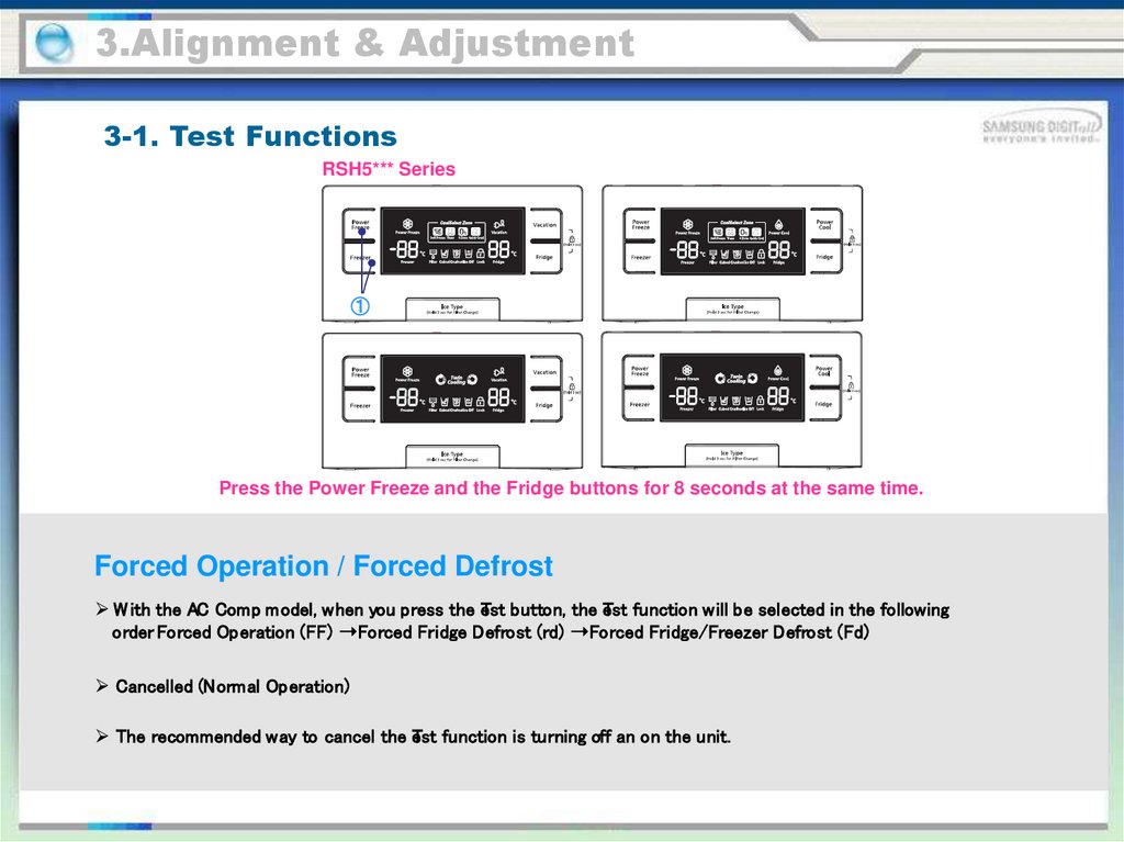
3.Alignment & Adjustment3-1. Test Functions
RSH5*** Series
①
Press the Power Freeze and the Fridge buttons for 8 seconds at the same time.
Forced Operation / Forced Defrost
W ith the AC Comp model, when you press the eTst button, the eTst function will be selected in the following
order. Forced Operation (FF) ➝Forced Fridge Defrost (rd) ➝Forced Fridge/Freezer Defrost (Fd)
Cancelled (Normal Operation)
The recommended way to cancel the eTst function is turning off an on the unit.
33.
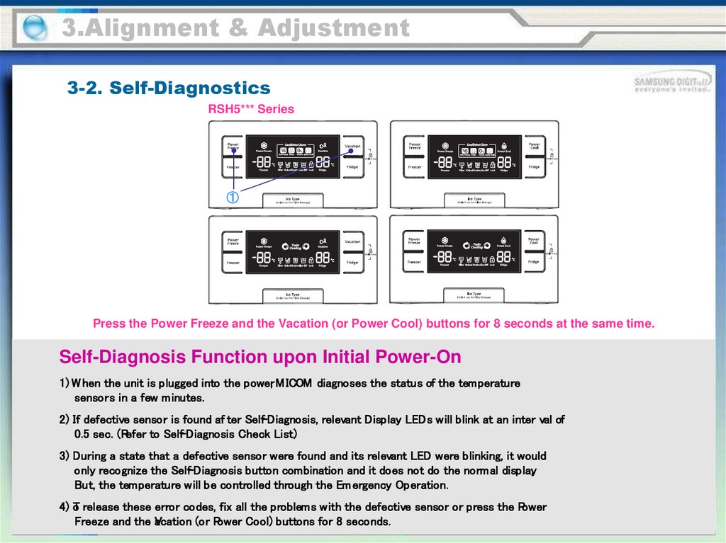
3.Alignment & Adjustment3-2. Self-Diagnostics
RSH5*** Series
①
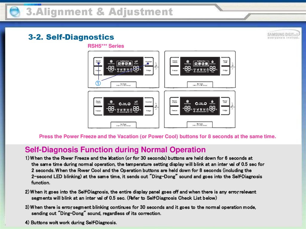
Press the Power Freeze and the Vacation (or Power Cool) buttons for 8 seconds at the same time.
Self-Diagnosis Function upon Initial Power-On
1) W hen the unit is plugged into the power, M ICOM diagnoses the status of the temperature
sensors in a few minutes.
2) If defective sensor is found af ter Self-Diagnosis, relevant Display LEDs will blink at an inter val of
0.5 sec. (Refer to Self-Diagnosis Check List)
3) During a state that a defective sensor were found and its relevant LED were blinking, it would
only recognize the Self-Diagnosis button combination and it does not do the normal display.
But, the temperature will be controlled through the Em ergency Operation.
4) oT release these error codes, fix all the problems with the defective sensor or press the Power
Freeze and the V
acation (or Power Cool) buttons for 8 seconds.
34.
3.Alignment & Adjustment3-2. Self-Diagnostics
RSH5*** Series
①
Press the Power Freeze and the Vacation (or Power Cool) buttons for 8 seconds at the same time.
Self-Diagnosis Function during Normal Operation
1) W hen the the Power Freeze and the aVcation (or for 30 seconds) buttons are held down for 6 seconds at
the sam e time during normal operation, the temperature setting display will blink at an inter val of 0.5 sec for
2 seconds. W hen the Power Cool and the Operation buttons are held down for 8 seconds (including the
2-second LED blinking) at the sam e time, it sends out "Ding-Dong” sound and goes into the Self-Diagnosis
function.
2) W hen it goes into the Self-Diagnosis, the entire display panel goes off and when there is any error, relevant
segm ents will blink at an inter val of 0.5 sec. (Refer to Self-Diagnosis Check List below)
3) W hen there is error, segm ent blinking continues for 30 seconds and it goes to the normal operation mode,
sending out "Ding-Dong" sound, regardless of its correction.
4) Buttons won't work during Self-Diagnosis.
35.
3.Alignment & Adjustment3-2. Self-Diagnostics
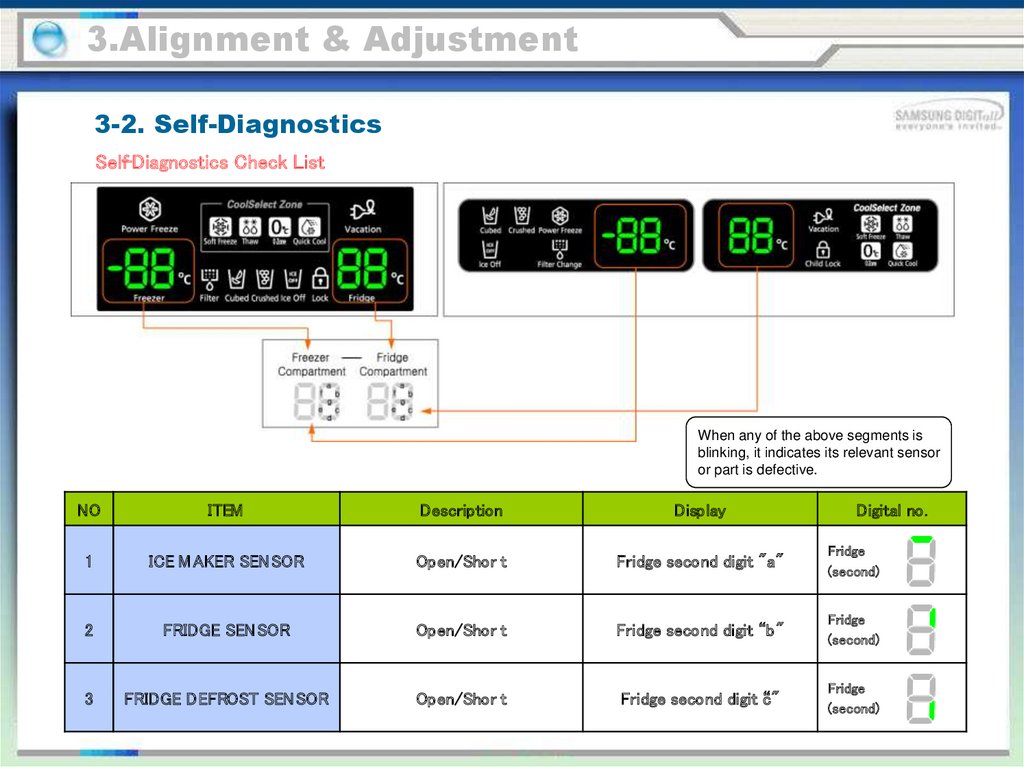
Self-Diagnostics Check List
When any of the above segments is
blinking, it indicates its relevant sensor
or part is defective.
NO
ITEM
Description
Display
Digital no.
1
ICE M AKER SEN SOR
Open/Shor t
Fridge second digit "a"
Fridge
(second)
2
FRIDGE SEN SOR
Open/Shor t
Fridge second digit “b"
Fridge
(second)
3
FRIDGE DEFROST SEN SOR
Open/Shor t
Fridge second digit “c"
Fridge
(second)
36.
3.Alignment & Adjustment3-2. Self-Diagnostics
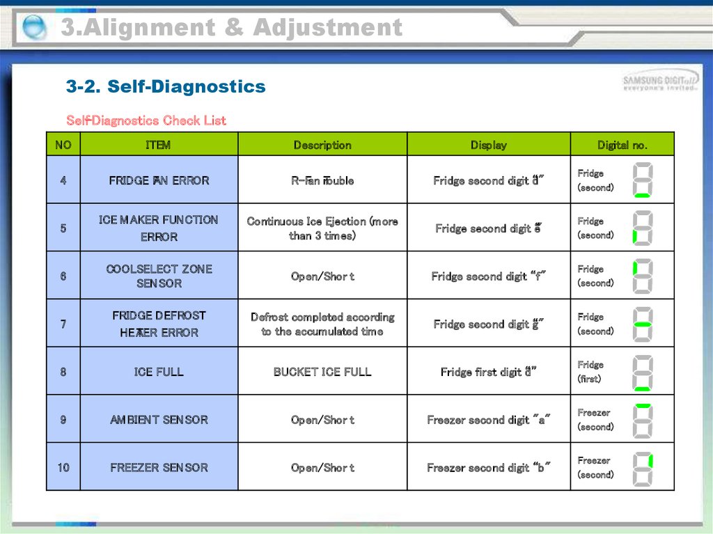
Self-Diagnostics Check List
NO
ITEM
Description
Display
Digital no.
4
FRIDGE FAN ERROR
R-Fan rTouble
Fridge second digit “d"
Fridge
(second)
5
ICE M AKER FUNCTION
ERROR
Continuous Ice Ejection (more
than 3 times)
Fridge second digit “e"
Fridge
(second)
6
COOLSELECT ZONE
SEN SOR
Open/Shor t
Fridge second digit “f"
Fridge
(second)
7
FRIDGE DEFROST
HEA
TER ERROR
Defrost completed according
to the accumulated time
Fridge second digit “g"
Fridge
(second)
8
ICE FULL
BUCKET ICE FULL
Fridge first digit “d”
9
AM BIENT SEN SOR
Open/Shor t
Freezer second digit "a"
Freezer
(second)
10
FREEZER SEN SOR
Open/Shor t
Freezer second digit “b"
Freezer
(second)
Fridge
(first)
37.
3.Alignment & Adjustment3-2. Self-Diagnostics
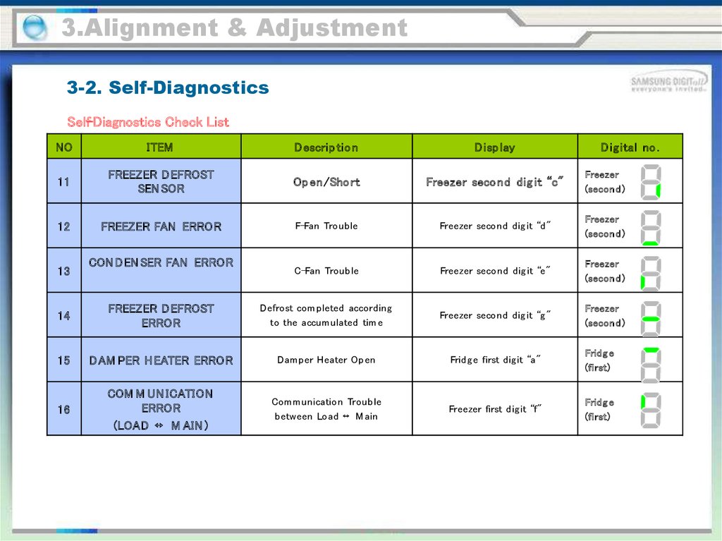
Self-Diagnostics Check List
NO
ITEM
D escrip tio n
D isp lay
11
FREEZER D EFROST
SEN SOR
Op en/Sho rt
Freezer seco nd dig it “c"
Freezer
(secon d )
12
FREEZER FAN ERROR
F-Fan Troub le
Freezer second d ig it “d "
Freezer
(secon d )
C-Fan Troub le
Freezer second d ig it “e"
Freezer
(secon d )
Freezer
(secon d )
13
CON DEN SER FAN ERROR
D ig ital no .
14
FREEZER D EFROST
ERROR
Defrost com p leted accord ing
to the accum ulated tim e
Freezer second d ig it “g "
15
DAM PER H EATER ERROR
Dam p er Heater Op en
Frid g e first d ig it “a"
Frid g e
(first)
16
COM M UN ICATION
ERROR
(LOAD ↔ M AIN )
Com m unication Troub le
b etween Load ↔ M ain
Freezer first d ig it “f"
Frid g e
(first)
38.
3.Alignment & Adjustment3-2. Self-Diagnostics
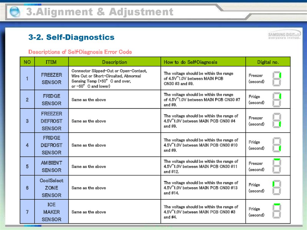
Descriptions of Self-Diagnosis Error Code
NO
ITEM
Description
How to do Self-Diagnosis
Digital no.
1
FREEZER
SEN SOR
Connector Slipped-Out or Open-Contact,
Wire Cut or Short-Circuited, Abnormal
Sensing Temp (+50°C and over,
or -50°C and lower)
The voltage should be within the range
of 4.5V~1.0V between MAIN PCB
CN30 #3 and #9.
Freezer
(second)
2
FRIDGE
SEN SOR
Same as the above
The voltage should be within the range
of 4.5V~1.0V between MAIN PCB CN30 #7
and #9.
Fridge
(second)
3
FREEZER
DEFROST
SEN SOR
Same as the above
The voltage should be within the range of
4.5V~1.0V between MAIN PCB CN30 #4
and #9.
Freezer
(second)
4
FRIDGE
DEFROST
SEN SOR
Same as the above
The voltage should be within the range of
4.5V~1.0V between MAIN PCB CN30 #10
and #9.
Fridge
(second)
5
AM BIENT
SEN SOR
Same as the above
The voltage should be within the range of
4.5V~1.0V between MAIN PCB CN30 #11
and #12.
Freezer
(second)
6
CoolSelect
ZONE
SEN SOR
Same as the above
The voltage should be within the range of
4.5V~1.0V between MAIN PCB CN30 #13
and #14.
Fridge
(second)
7
ICE
MAKER
SEN SOR
Same as the above
The voltage should be within the range of
4.5V~1.0V between MAIN PCB CN30 #3
and #4.
Fridge
(second)
39.
3.Alignment & Adjustment3-2. Self-Diagnostics
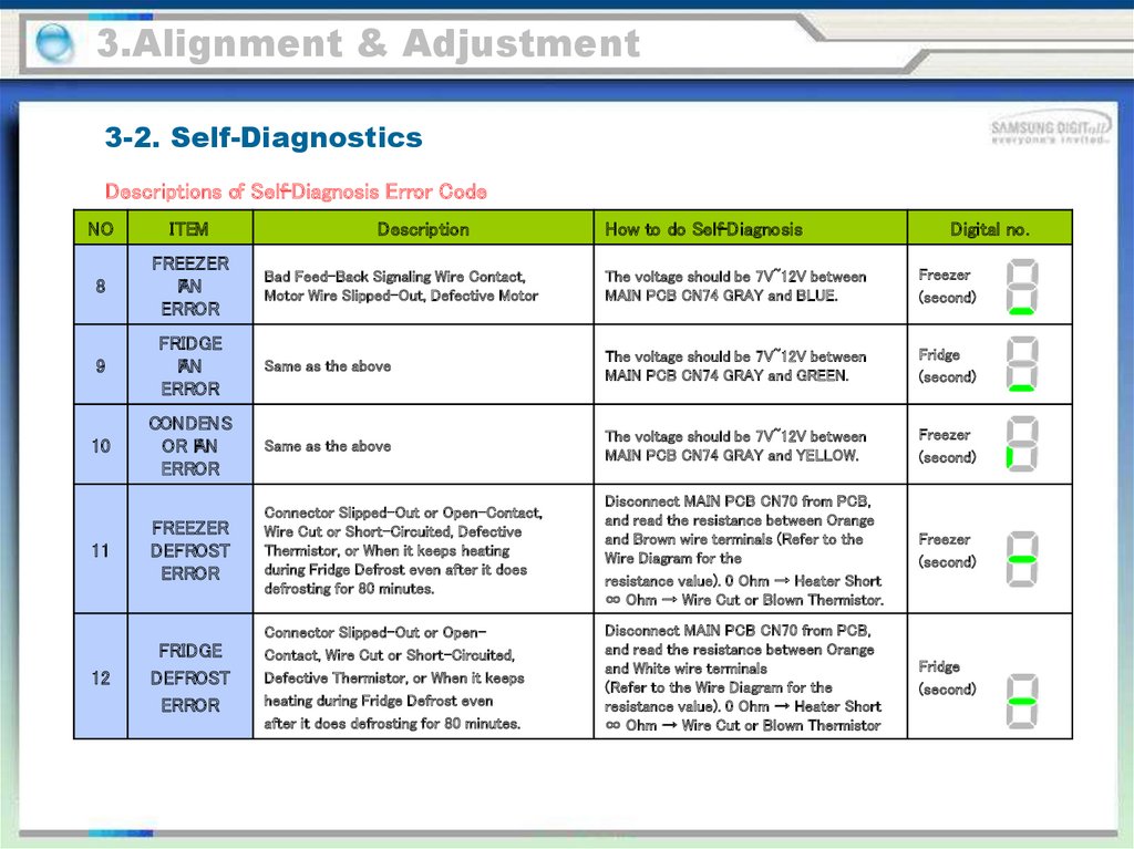
Descriptions of Self-Diagnosis Error Code
NO
ITEM
8
FREEZER
FAN
ERROR
Description
How to do Self-Diagnosis
Digital no.
Bad Feed-Back Signaling Wire Contact,
Motor Wire Slipped-Out, Defective Motor
The voltage should be 7V~12V between
MAIN PCB CN74 GRAY and BLUE.
Freezer
(second)
9
FRIDGE
FAN
ERROR
Same as the above
The voltage should be 7V~12V between
MAIN PCB CN74 GRAY and GREEN.
Fridge
(second)
10
CONDENS
OR FAN
ERROR
Same as the above
The voltage should be 7V~12V between
MAIN PCB CN74 GRAY and YELLOW.
Freezer
(second)
FREEZER
DEFROST
ERROR
Connector Slipped-Out or Open-Contact,
Wire Cut or Short-Circuited, Defective
Thermistor, or When it keeps heating
during Fridge Defrost even after it does
defrosting for 80 minutes.
Disconnect MAIN PCB CN70 from PCB,
and read the resistance between Orange
and Brown wire terminals (Refer to the
Wire Diagram for the
resistance value). 0 Ohm → Heater Short
∞ Ohm → Wire Cut or Blown Thermistor.
Freezer
(second)
FRIDGE
DEFROST
ERROR
Connector Slipped-Out or OpenContact, Wire Cut or Short-Circuited,
Defective Thermistor, or When it keeps
heating during Fridge Defrost even
after it does defrosting for 80 minutes.
Disconnect MAIN PCB CN70 from PCB,
and read the resistance between Orange
and White wire terminals
(Refer to the Wire Diagram for the
resistance value). 0 Ohm → Heater Short
∞ Ohm → Wire Cut or Blown Thermistor
Fridge
(second)
11
12
40.
3.Alignment & Adjustment3-2. Self-Diagnostics
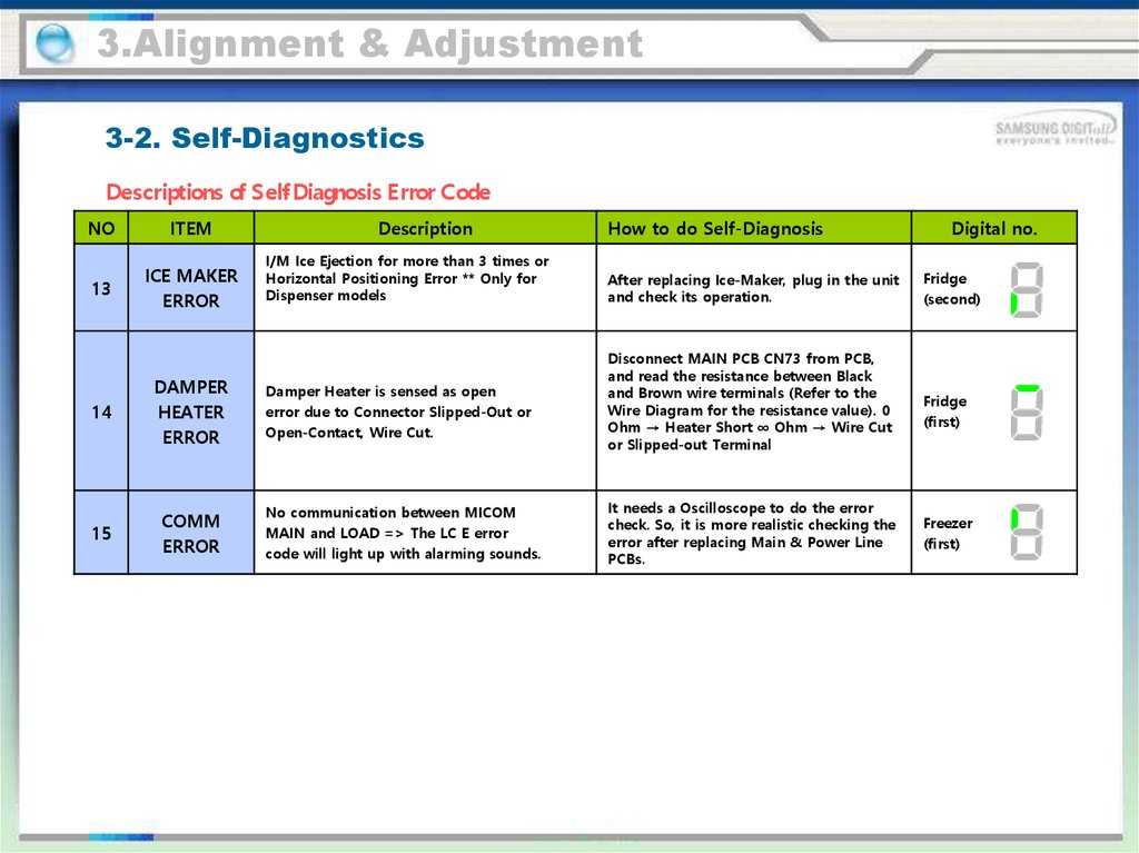
Descriptions of Self- Diagnosis Error Code
NO
ITEM
13
ICE MAKER
ERROR
14
DAMPER
HEATER
ERROR
15
COMM
ERROR
Description
I/M Ice Ejection for more than 3 times or
Horizontal Positioning Error ** Only for
Dispenser models
Damper Heater is sensed as open
error due to Connector Slipped-Out or
Open-Contact, Wire Cut.
No communication between MICOM
MAIN and LOAD => The LC E error
code will light up with alarming sounds.
How to do Self-Diagnosis
After replacing Ice-Maker, plug in the unit
and check its operation.
Disconnect MAIN PCB CN73 from PCB,
and read the resistance between Black
and Brown wire terminals (Refer to the
Wire Diagram for the resistance value). 0
Ohm → Heater Short ∞ Ohm → Wire Cut
or Slipped-out Terminal
It needs a Oscilloscope to do the error
check. So, it is more realistic checking the
error after replacing Main & Power Line
PCBs.
Digital no.
Fridge
(second)
Fridge
(first)
Freezer
(first)
41.
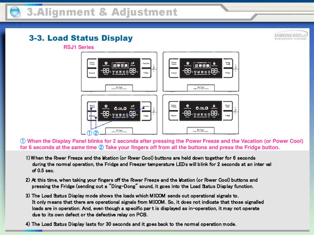
3.Alignment & Adjustment3-3. Load Status Display
RSJ1 Series
①②
① When the Display Panel blinks for 2 seconds after pressing the Power Freeze and the Vacation (or Power Cool)
for 6 seconds at the same time ② Take your fingers off from all the buttons and press the Fridge button.
1) W hen the Power Freeze and the V
acation (or Power Cool) buttons are held down together for 6 seconds
during the normal operation, the Fridge and Freezer temperature LEDs will blink for 2 seconds at an inter val
of 0.5 sec.
2) At this time, when taking your fingers off the Power Freeze and the V
acation (or Power Cool) buttons and
pressing the Fridge (sending out a "Ding-Dong" sound, it goes into the Load Status Display function.
3) The Load Status Display mode shows the loads which M ICOM sends out operational signals to.
It only means that there are operational signals from M ICOM . So, it does not indicate that those signalled
loads are in operation. And, even though a specific par t is displayed as in-operation, it may not operate
due to its own defect or the defective relay on PCB.
4) The Load Status Display lasts for 30 seconds and it goes back to the normal operation mode.
42.
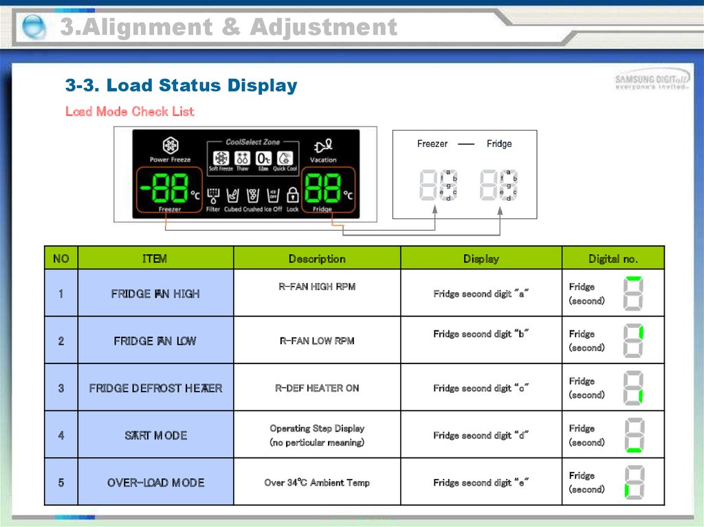
3.Alignment & Adjustment3-3. Load Status Display
Load Mode Check List
NO
ITEM
Description
1
FRIDGE FAN HIGH
2
FRIDGE FAN LOW
R-FAN LOW RPM
3
FRIDGE DEFROST HEA
TER
R-DEF HEATER ON
Fridge second digit “c"
Fridge
(second)
4
ST
ART M ODE
Operating Step Display
(no perticular meaning)
Fridge second digit “d"
Fridge
(second)
5
OVER-LOAD M ODE
Over 34℃ Ambient Temp
Fridge second digit “e"
Fridge
(second)
R-FAN HIGH RPM
Display
Fridge second digit "a"
Fridge second digit “b"
Digital no.
Fridge
(second)
Fridge
(second)
43.
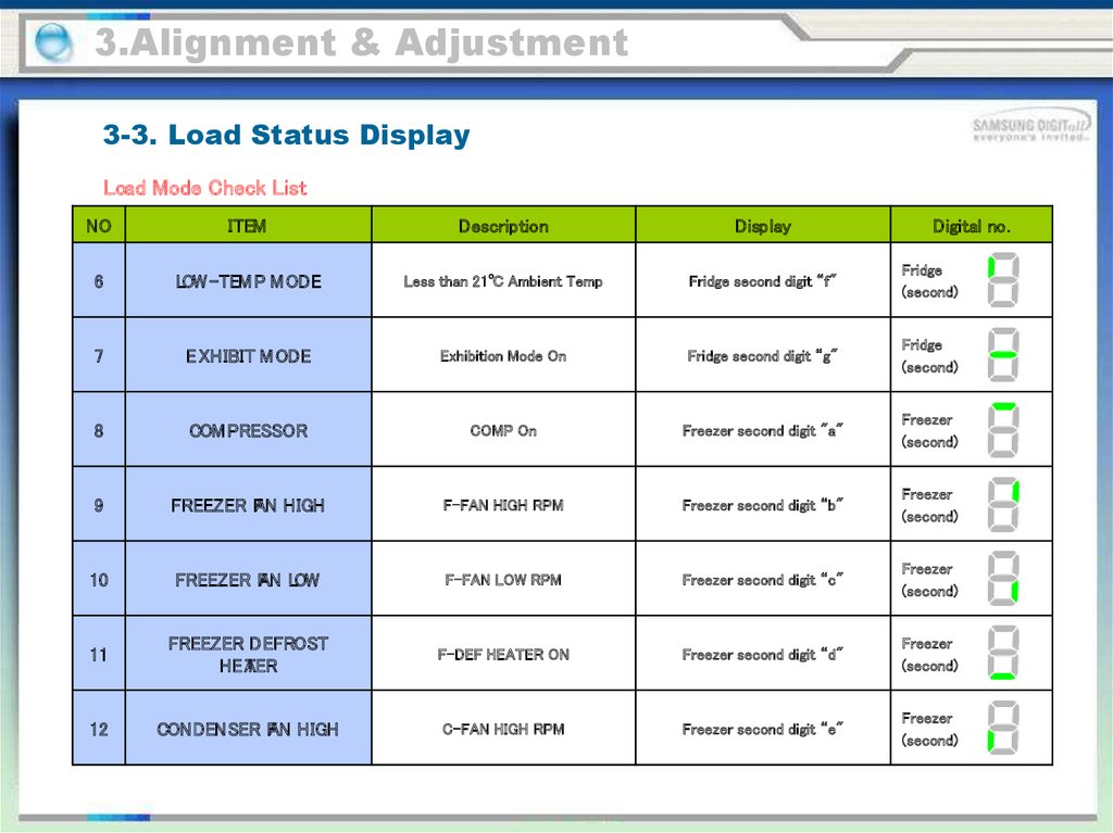
3.Alignment & Adjustment3-3. Load Status Display
Load Mode Check List
NO
ITEM
Description
Display
Digital no.
6
LOW -TEM P M ODE
Less than 21℃ Ambient Temp
Fridge second digit “f"
Fridge
(second)
7
E XHIBIT M ODE
Exhibition Mode On
Fridge second digit “g"
Fridge
(second)
8
COM PRESSOR
COMP On
Freezer second digit "a"
Freezer
(second)
9
FREEZER FAN HIGH
F-FAN HIGH RPM
Freezer second digit “b"
Freezer
(second)
10
FREEZER FAN LOW
F-FAN LOW RPM
Freezer second digit “c"
Freezer
(second)
11
FREEZER DEFROST
HEA
TER
F-DEF HEATER ON
Freezer second digit “d"
Freezer
(second)
12
CONDENSER FAN HIGH
C-FAN HIGH RPM
Freezer second digit “e"
Freezer
(second)
44.
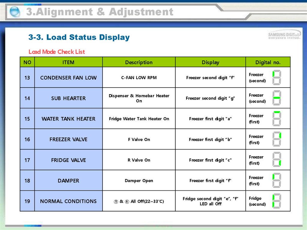
3.Alignment & Adjustment3-3. Load Status Display
Load Mode Check List
NO
ITEM
Description
Display
Digital no.
13
CONDENSER FAN LOW
C-FAN LOW RPM
Freezer second digit “f"
Freezer
(second)
14
SUB HEARTER
Dispenser & Homebar Heater
On
Freezer second digit “g"
Freezer
(second)
15
WATER TANK HEATER
Fridge Water Tank Heater On
Freezer first digit "a"
Freezer
(first)
16
FREEZER VALVE
F Valve On
Freezer first digit “b"
Freezer
(first)
17
FRIDGE VALVE
R Valve On
Freezer first digit “c"
Freezer
(first)
18
DAMPER
Damper Open
Freezer first digit “f"
Freezer
(first)
19
NORMAL CONDITIONS
⑤ & ⑥ All Off(22~33℃)
Fridge second digit “e”, “f”
LED all Off
Fridge
(second)
45.
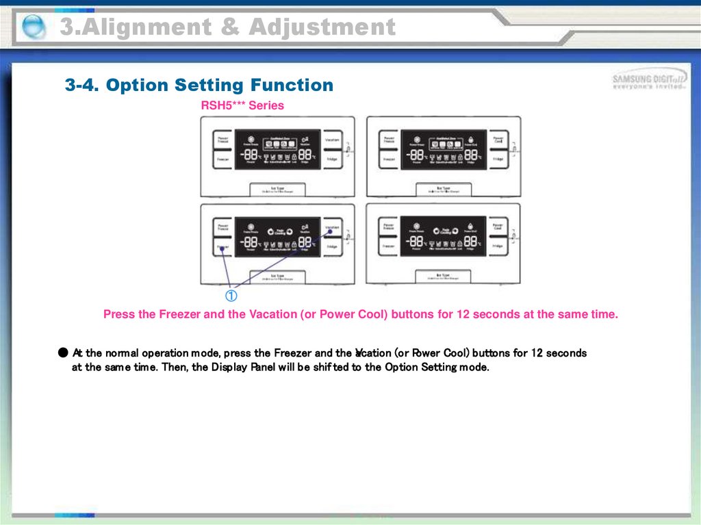
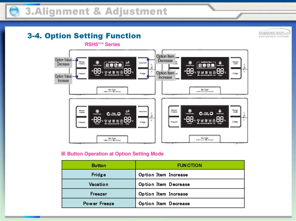
3.Alignment & Adjustment3-4. Option Setting Function
RSH5*** Series
①
Press the Freezer and the Vacation (or Power Cool) buttons for 12 seconds at the same time.
● At the normal operation mode, press the Freezer and the V
acation (or Power Cool) buttons for 12 seconds
at the sam e time. Then, the Display Panel will be shif ted to the Option Setting mode.
46.
3.Alignment & Adjustment3-4. Option Setting Function
RSH5*** Series
※ Button Operation at Option Setting Mode
Button
FUN CTION
Fridg e
Op tio n Item Increase
Vacatio n
Op tio n Item D ecrease
Freezer
Op tio n Item Increase
Po w er Freeze
Op tio n Item D ecrease
47.
3.Alignment & Adjustment3-4. Option Setting Function
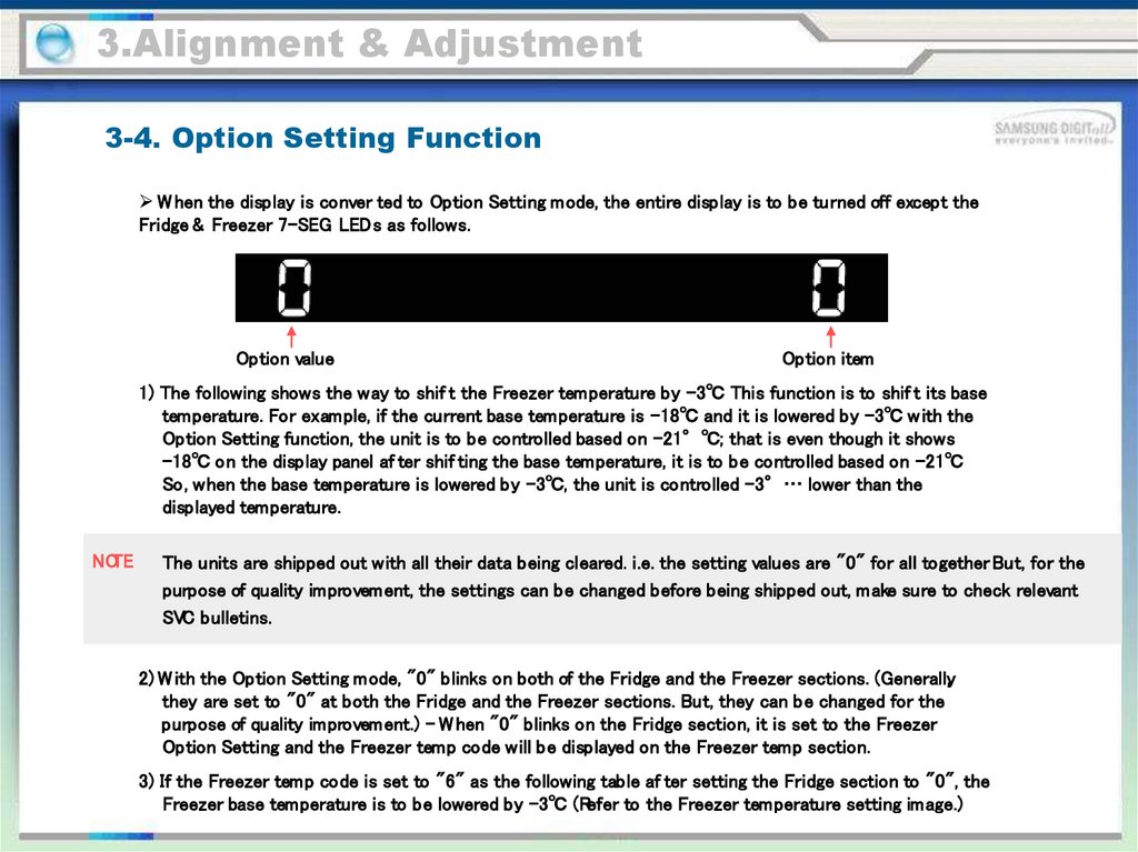
W hen the display is conver ted to Option Setting mode, the entire display is to be turned off except the
Fridge & Freezer 7-SEG LEDs as follows.
Option value
Option item
1) The following shows the way to shif t the Freezer temperature by -3℃ This function is to shif t its base
temperature. For example, if the current base temperature is -18℃ and it is lowered by -3℃ w ith the
Option Setting function, the unit is to be controlled based on -21°℃; that is even though it shows
-18℃ on the display panel af ter shif ting the base temperature, it is to be controlled based on -21℃
So, when the base temperature is lowered by -3℃, the unit is controlled -3°… lower than the
displayed temperature.
NOTE
The units are shipped out with all their data being cleared. i.e. the setting values are "0" for all together. But, for the
purpose of quality improvement, the settings can be changed before being shipped out, make sure to check relevant
SVC bulletins.
2) W ith the Option Setting mode, "0" blinks on both of the Fridge and the Freezer sections. (Generally,
they are set to "0" at both the Fridge and the Freezer sections. But, they can be changed for the
purpose of quality improvement.) - W hen "0" blinks on the Fridge section, it is set to the Freezer
Option Setting and the Freezer temp code will be displayed on the Freezer temp section.
3) If the Freezer temp code is set to "6" as the following table af ter setting the Fridge section to "0", the
Freezer base temperature is to be lowered by -3℃ (Refer to the Freezer temperature setting image.)
48.
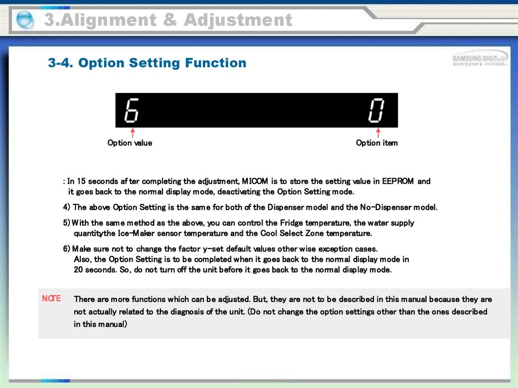
3.Alignment & Adjustment3-4. Option Setting Function
Option value
Option item
: In 15 seconds af ter completing the adjustment, M ICOM is to store the setting value in EEPROM and
it goes back to the normal display mode, deactivating the Option Setting mode.
4) The above Option Setting is the sam e for both of the Dispenser model and the No-Dispenser model.
5) W ith the sam e method as the above, you can control the Fridge temperature, the water supply
quantity, the Ice-M aker sensor temperature and the Cool Select Zone temperature.
6) M ake sure not to change the factor y-set default values other wise exception cases.
Also, the Option Setting is to be completed when it goes back to the normal display mode in
20 seconds. So, do not turn off the unit before it goes back to the normal display mode.
NOTE
There are more functions which can be adjusted. But, they are not to be described in this manual because they are
not actually related to the diagnosis of the unit. (Do not change the option settings other than the ones described
in this manual)
49.
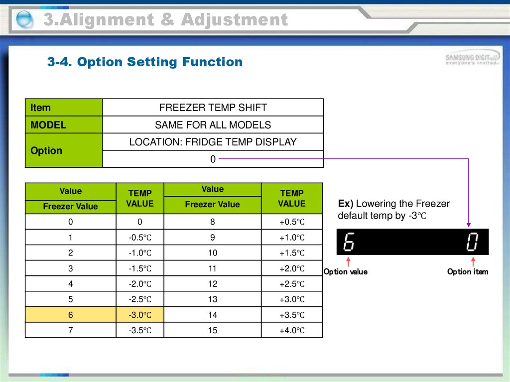
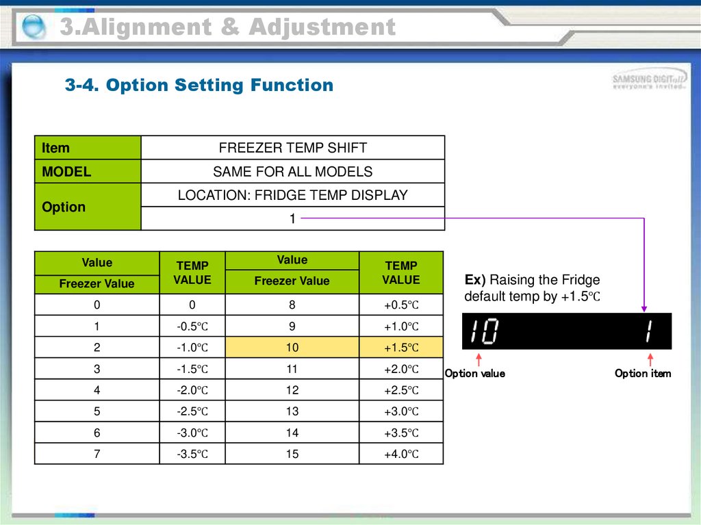
3.Alignment & Adjustment3-4. Option Setting Function
Item
FREEZER TEMP SHIFT
MODEL
SAME FOR ALL MODELS
LOCATION: FRIDGE TEMP DISPLAY
Option
0
Value
Value
Freezer Value
TEMP
VALUE
Freezer Value
TEMP
VALUE
0
0
8
+0.5℃
1
-0.5℃
9
+1.0℃
2
-1.0℃
10
+1.5℃
3
-1.5℃
11
+2.0℃
4
-2.0℃
12
+2.5℃
5
-2.5℃
13
+3.0℃
6
-3.0℃
14
+3.5℃
7
-3.5℃
15
+4.0℃
Ex) Lowering the Freezer
default temp by -3℃
Option value
Option item
50.
3.Alignment & Adjustment3-4. Option Setting Function
Item
FREEZER TEMP SHIFT
MODEL
SAME FOR ALL MODELS
LOCATION: FRIDGE TEMP DISPLAY
Option
1
Value
Value
Freezer Value
TEMP
VALUE
Freezer Value
TEMP
VALUE
0
0
8
+0.5℃
1
-0.5℃
9
+1.0℃
2
-1.0℃
10
+1.5℃
3
-1.5℃
11
+2.0℃
4
-2.0℃
12
+2.5℃
5
-2.5℃
13
+3.0℃
6
-3.0℃
14
+3.5℃
7
-3.5℃
15
+4.0℃
Ex) Raising the Fridge
default temp by +1.5℃
Option value
Option item
51.
3.Alignment & Adjustment3-4. Option Setting Function
It controls the water supply quantity with the Flow Sensor.
item
Display Position
Ice-Maker Water Supply
Qty Control
2
Water Supply Quantity
Option Value
(Freezer Temp)
85CC
0
95CC
1
Ex) Changing the water supply quantity to 85cc
Option value
Option item
52.
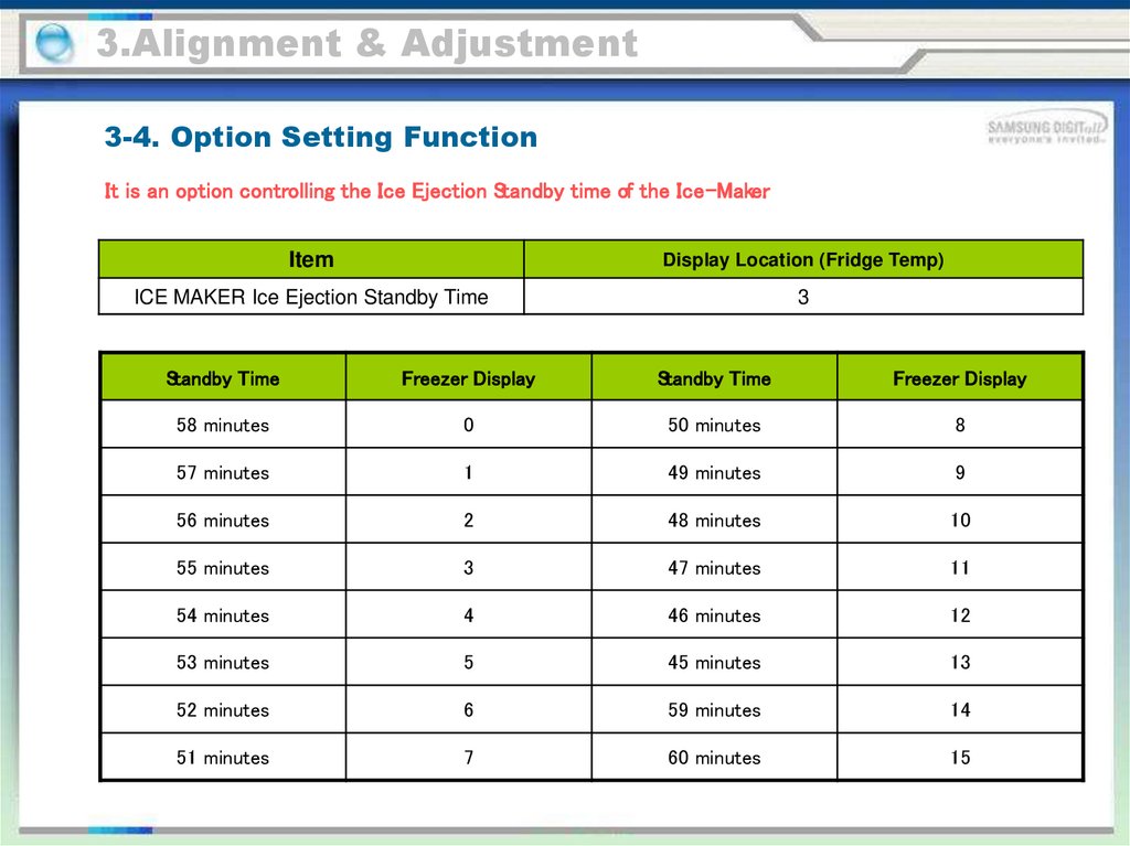
3.Alignment & Adjustment3-4. Option Setting Function
It is an option controlling the Ice Ejection Standby time of the Ice-Maker.
Item
Display Location (Fridge Temp)
ICE MAKER Ice Ejection Standby Time
3
Standby Time
Freezer Display
Standby Time
Freezer Display
58 minutes
0
50 minutes
8
57 minutes
1
49 minutes
9
56 minutes
2
48 minutes
10
55 minutes
3
47 minutes
11
54 minutes
4
46 minutes
12
53 minutes
5
45 minutes
13
52 minutes
6
59 minutes
14
51 minutes
7
60 minutes
15
53.
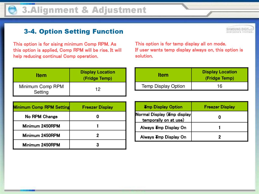
3.Alignment & Adjustment3-4. Option Setting Function
This option is for sising minimum Comp RPM. As
this option is applied, Comp RPM will be rise. It will
help reducing continual Comp operation.
This option is for temp display all on mode.
If user wants temp display always on, this option is
solution.
Item
Display Location
(Fridge Temp)
Temp Display Option
16
Freezer Display
T
emp Display Option
Freezer Display
No RPM Change
0
Normal Display (T
emp display
temporally on at use)
0
Minimum 2450RPM
1
Always T
emp Display On
1
Minimum 2450RPM
2
Always T
emp Display On
2
Minimum 2450RPM
3
Item
Display Location
(Fridge Temp)
Minimum Comp RPM
Setting
12
Minimum Comp RPM Setting
54.
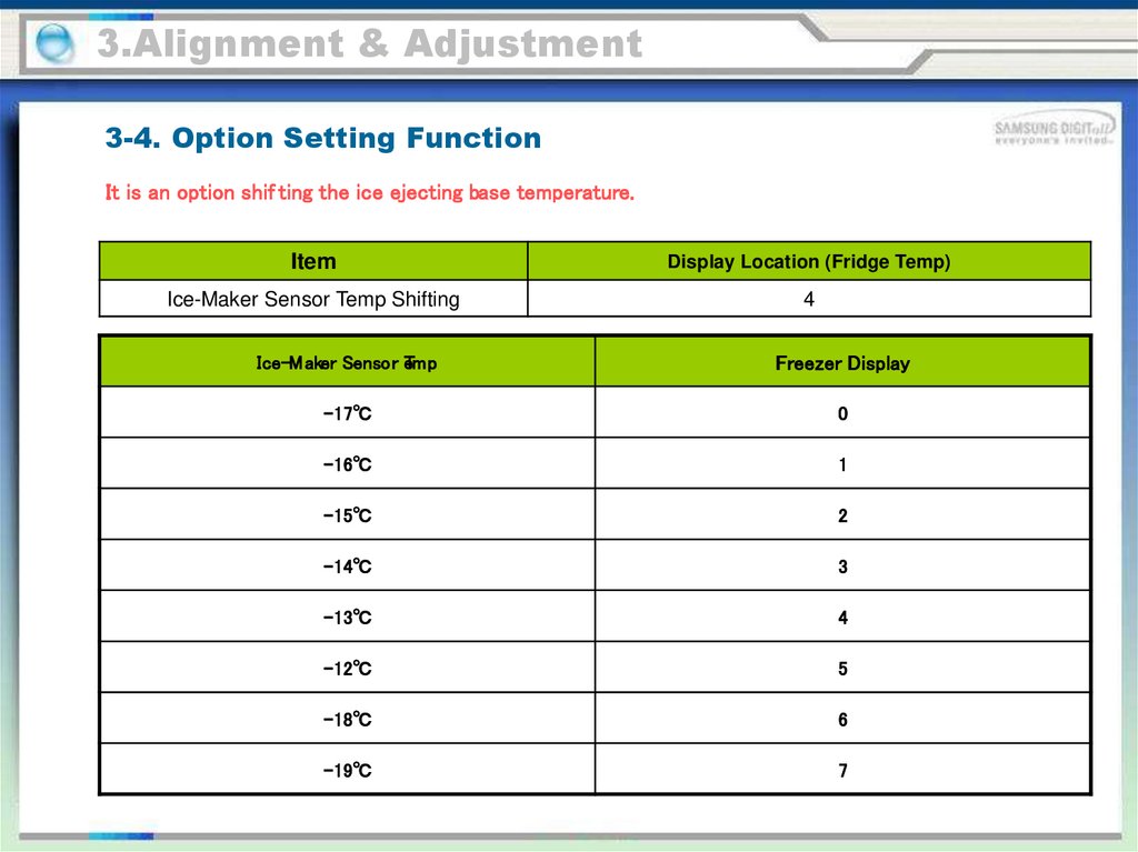
3.Alignment & Adjustment3-4. Option Setting Function
It is an option shif ting the ice ejecting base temperature.
Item
Display Location (Fridge Temp)
Ice-Maker Sensor Temp Shifting
4
Ice-M aker Sensor eTmp
Freezer Display
-17℃
0
-16℃
1
-15℃
2
-14℃
3
-13℃
4
-12℃
5
-18℃
6
-19℃
7
55.
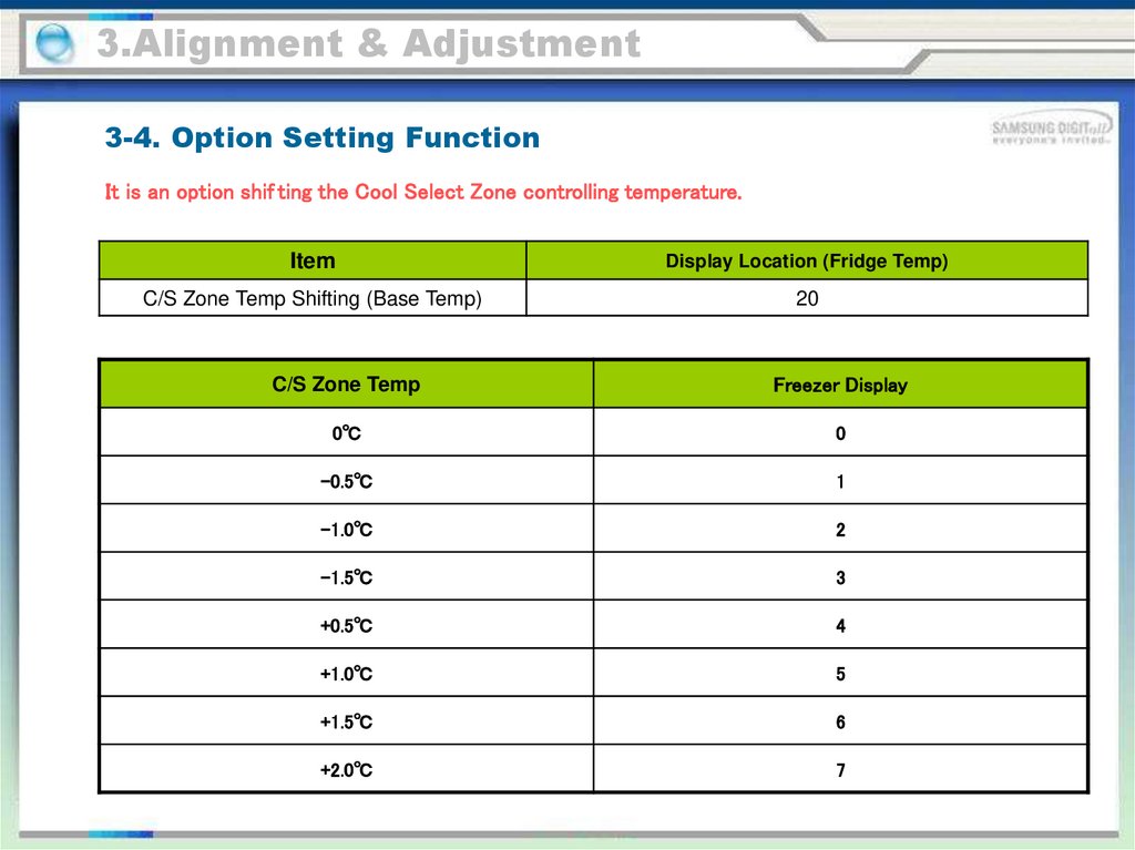
3.Alignment & Adjustment3-4. Option Setting Function
It is an option shif ting the Cool Select Zone controlling temperature.
Item
Display Location (Fridge Temp)
C/S Zone Temp Shifting (Base Temp)
20
C/S Zone Temp
Freezer Display
0℃
0
-0.5℃
1
-1.0℃
2
-1.5℃
3
+0.5℃
4
+1.0℃
5
+1.5℃
6
+2.0℃
7
56.
4.Disassembly & Reassembly4-1. Necessary tools for disassembly and reassembly
Unplug the refrigerator before cleaning and making repairs.
Do not dissemble or repair the refrigerator by yourself.
You run risk of causing a fire, malfunction and/or personal injury.
Remove any foreign matter or dust from the power plug pins.
Otherwise there is a risk of fire.
Do not use a cord that shows cracks or abrasion damage along its length or at either end.
Do not plug several appliances into the same multiple power board. The refrigerator should
always be plugged into its own individual electrical which has a voltage rating that matched
the rating plate.
- This provides the best performance and also prevents overloading house wiring circuits,
which could cause a fire hazard from overheated wires.
• Do not install the refrigerator in a damp place or place where it may come in contact with
water.
- Deteriorated insulation of electrical parts may cause an electric shock or fire.
• The refrigerator must be grounded.
- You must ground the refrigerator to prevent any power leakages or electric shocks caused
by
current leakage from the refrigerator.
• Do not put bottles or glass containers in the freezer.
- When the contents freeze, the glass may break and cause personal injury.
• Do not store volatile or flammable substances in the refrigerator.
- The storage of benzene, thinner, alcohol, ether, LP gas and other such products may cause
57.
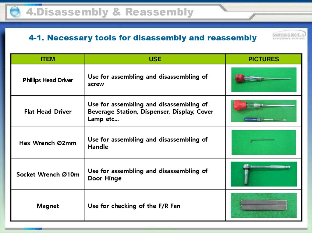
4.Disassembly & Reassembly4-1. Necessary tools for disassembly and reassembly
ITEM
USE
Phillips Head Driver
Use for assembling and disassembling of
screw
Flat Head Driver
Use for assembling and disassembling of
Beverage Station, Dispenser, Display, Cover
Lamp etc...
Hex Wrench Ø2mm
Use for assembling and disassembling of
Handle
Socket Wrench Ø10m
Use for assembling and disassembling of
Door Hinge
Magnet
Use for checking of the F/R Fan
PICTURES
58.
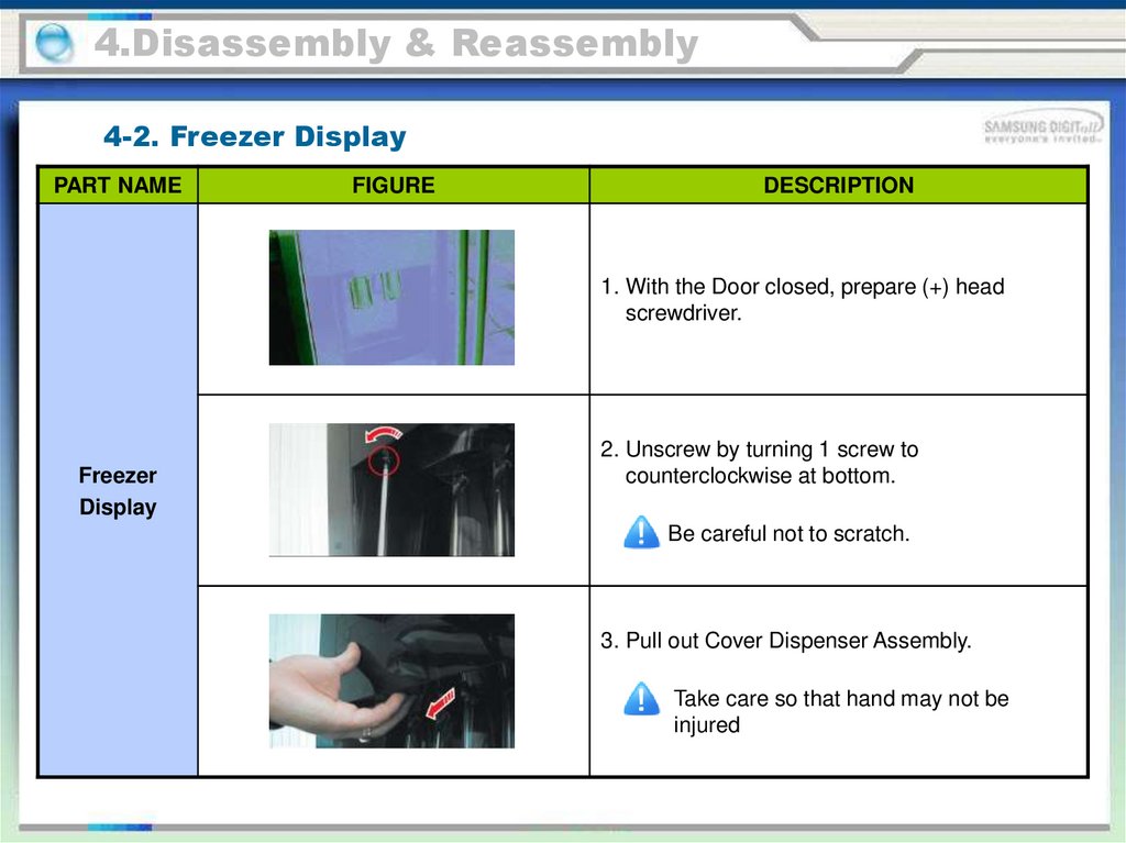
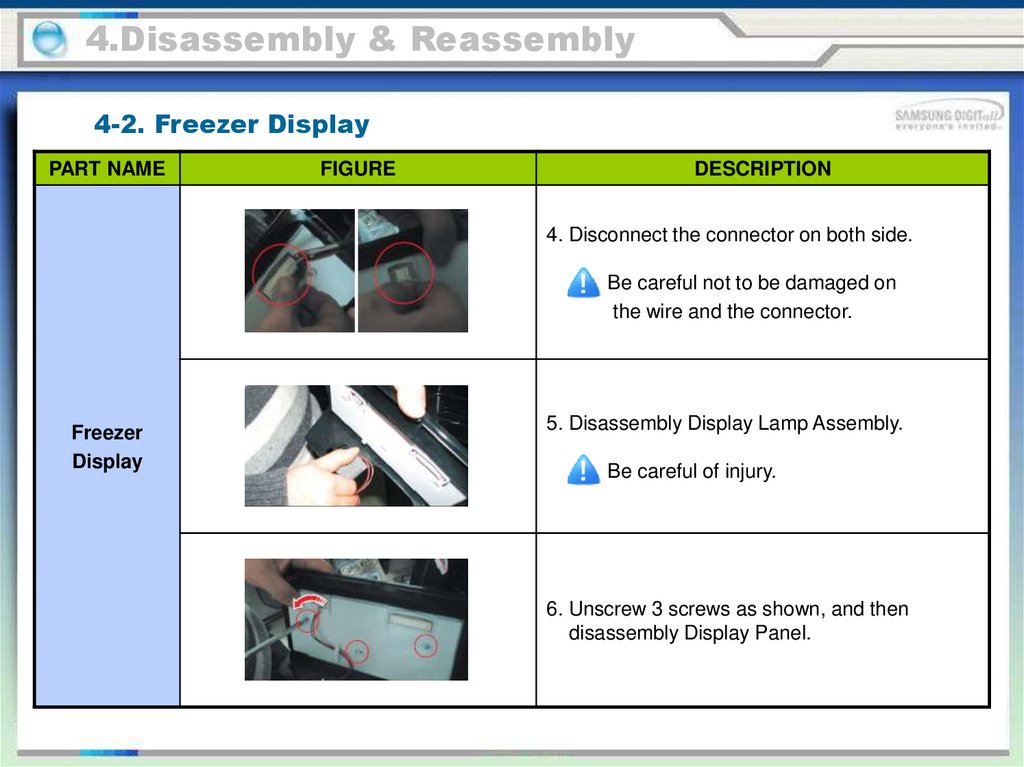
4.Disassembly & Reassembly4-2. Freezer Display
PART NAME
FIGURE
DESCRIPTION
1. With the Door closed, prepare (+) head
screwdriver.
Freezer
Display
2. Unscrew by turning 1 screw to
counterclockwise at bottom.
Be careful not to scratch.
3. Pull out Cover Dispenser Assembly.
Take care so that hand may not be
injured
59.
4.Disassembly & Reassembly4-2. Freezer Display
PART NAME
FIGURE
DESCRIPTION
4. Disconnect the connector on both side.
Be careful not to be damaged on
the wire and the connector.
Freezer
Display
5. Disassembly Display Lamp Assembly.
Be careful of injury.
6. Unscrew 3 screws as shown, and then
disassembly Display Panel.
60.
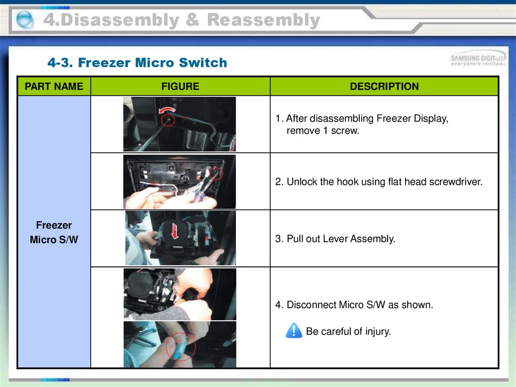
4.Disassembly & Reassembly4-3. Freezer Micro Switch
PART NAME
FIGURE
DESCRIPTION
1. After disassembling Freezer Display,
remove 1 screw.
2. Unlock the hook using flat head screwdriver.
Freezer
Micro S/W
3. Pull out Lever Assembly.
4. Disconnect Micro S/W as shown.
Be careful of injury.
61.
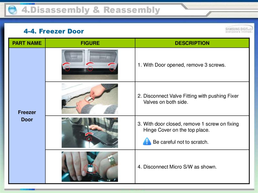
4.Disassembly & Reassembly4-4. Freezer Door
PART NAME
FIGURE
DESCRIPTION
1. With Door opened, remove 3 screws.
2. Disconnect Valve Fitting with pushing Fixer
Valves on both side.
Freezer
Door
3. With door closed, remove 1 screw on fixing
Hinge Cover on the top place.
Be careful not to scratch.
4. Disconnect Micro S/W as shown.
62.
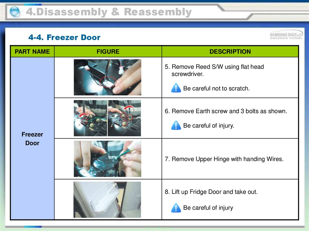
4.Disassembly & Reassembly4-4. Freezer Door
PART NAME
FIGURE
DESCRIPTION
5. Remove Reed S/W using flat head
screwdriver.
Be careful not to scratch.
6. Remove Earth screw and 3 bolts as shown.
Be careful of injury.
Freezer
Door
7. Remove Upper Hinge with handing Wires.
8. Lift up Fridge Door and take out.
Be careful of injury
63.
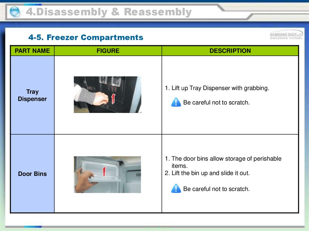
4.Disassembly & Reassembly4-5. Freezer Compartments
PART NAME
Tray
Dispenser
Door Bins
FIGURE
DESCRIPTION
1. Lift up Tray Dispenser with grabbing.
Be careful not to scratch.
1. The door bins allow storage of perishable
items.
2. Lift the bin up and slide it out.
Be careful not to scratch.
64.
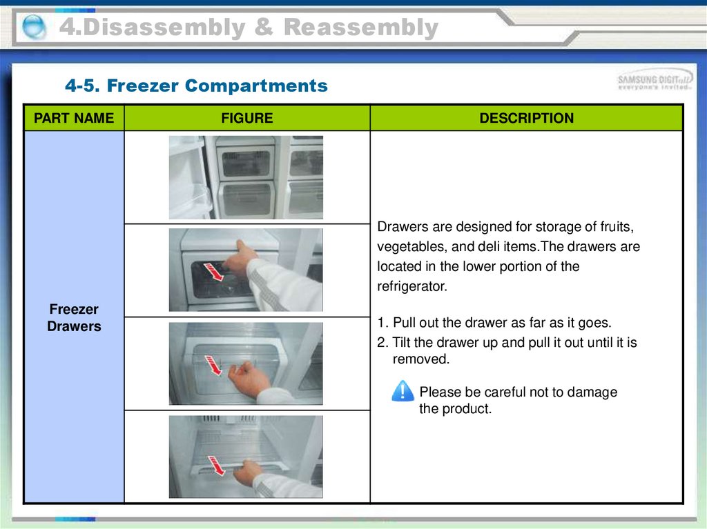
4.Disassembly & Reassembly4-5. Freezer Compartments
PART NAME
FIGURE
DESCRIPTION
Drawers are designed for storage of fruits,
vegetables, and deli items.The drawers are
located in the lower portion of the
refrigerator.
Freezer
Drawers
1. Pull out the drawer as far as it goes.
2. Tilt the drawer up and pull it out until it is
removed.
Please be careful not to damage
the product.
65.
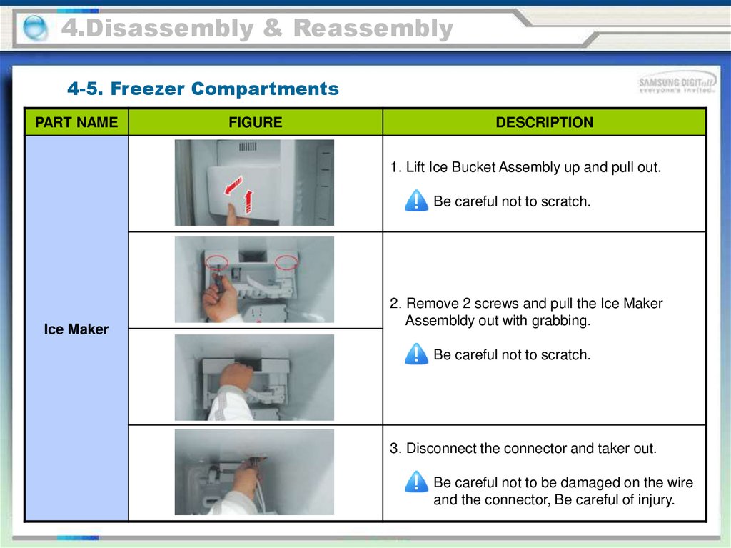
4.Disassembly & Reassembly4-5. Freezer Compartments
PART NAME
FIGURE
DESCRIPTION
1. Lift Ice Bucket Assembly up and pull out.
Be careful not to scratch.
Ice Maker
2. Remove 2 screws and pull the Ice Maker
Assembldy out with grabbing.
Be careful not to scratch.
3. Disconnect the connector and taker out.
Be careful not to be damaged on the wire
and the connector, Be careful of injury.
66.
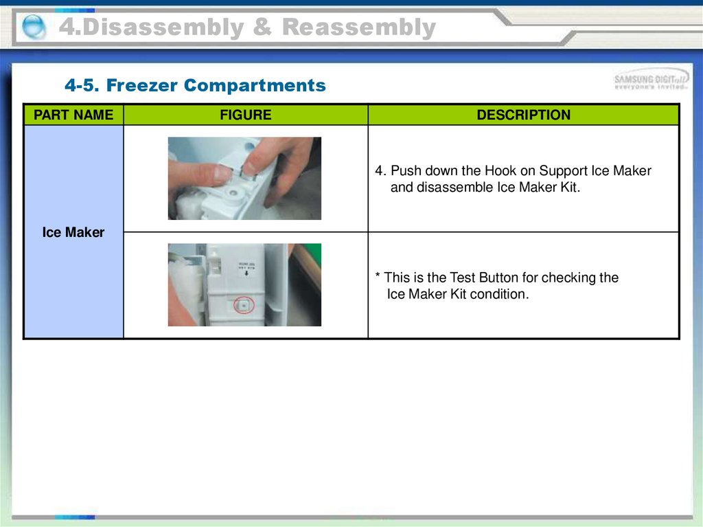
4.Disassembly & Reassembly4-5. Freezer Compartments
PART NAME
FIGURE
DESCRIPTION
4. Push down the Hook on Support Ice Maker
and disassemble Ice Maker Kit.
Ice Maker
* This is the Test Button for checking the
Ice Maker Kit condition.
67.
4.Disassembly & Reassembly4-5. Freezer Compartments
PART NAME
FIGURE
DESCRIPTION
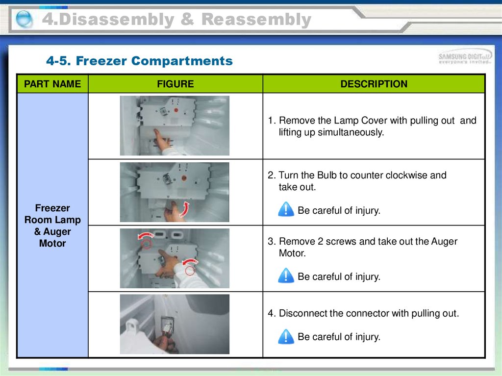
1. Remove the Lamp Cover with pulling out and
lifting up simultaneously.
2. Turn the Bulb to counter clockwise and
take out.
Freezer
Room Lamp
& Auger
Motor
Be careful of injury.
3. Remove 2 screws and take out the Auger
Motor.
Be careful of injury.
4. Disconnect the connector with pulling out.
Be careful of injury.
68.
4.Disassembly & Reassembly4-5. Freezer Compartments
PART NAME
FIGURE
DESCRIPTION
5. Remove the Cover Auger Motor using flat
head screwdriver.
Freezer
Room Lamp
& Auger
Motor
Be careful of injury.
6. After removing the Cover Auger Motor,
unlock the Lamp Socket with pushing down.
69.
4.Disassembly & Reassembly4-5. Freezer Compartments
PART NAME
FIGURE
DESCRIPTION
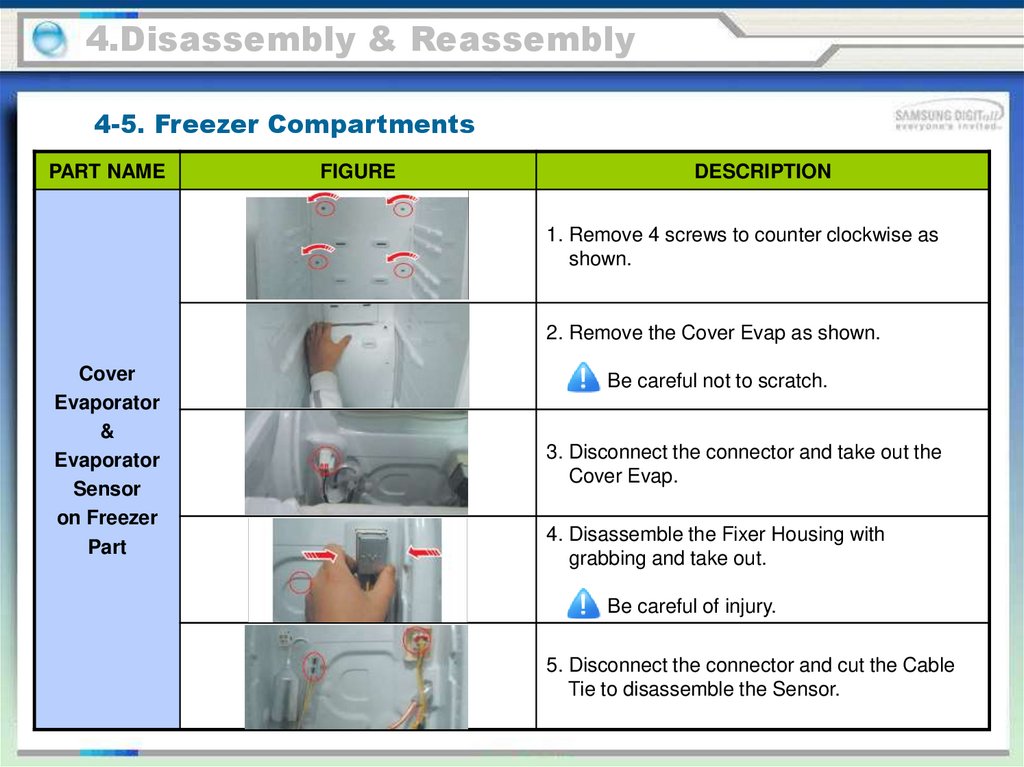
1. Remove 4 screws to counter clockwise as
shown.
2. Remove the Cover Evap as shown.
Cover
Evaporator
&
Evaporator
Sensor
on Freezer
Part
Be careful not to scratch.
3. Disconnect the connector and take out the
Cover Evap.
4. Disassemble the Fixer Housing with
grabbing and take out.
Be careful of injury.
5. Disconnect the connector and cut the Cable
Tie to disassemble the Sensor.
70.
4.Disassembly & Reassembly4-5. Freezer Compartments
PART NAME
FIGURE
DESCRIPTION
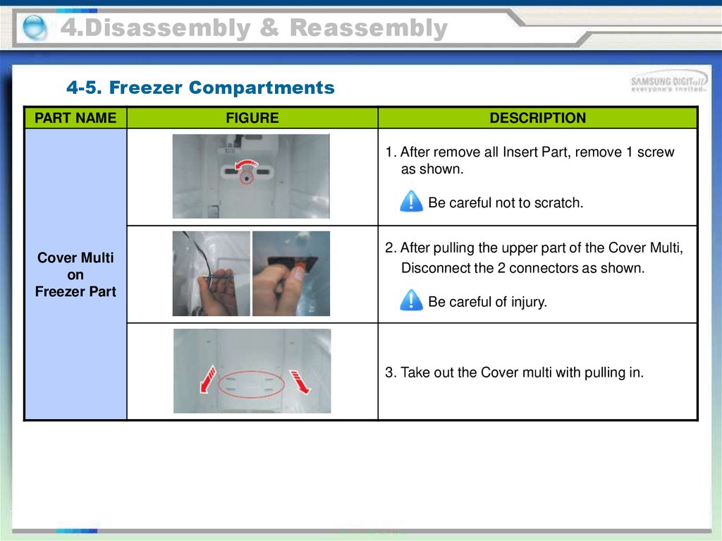
1. After remove all Insert Part, remove 1 screw
as shown.
Be careful not to scratch.
Cover Multi
on
Freezer Part
2. After pulling the upper part of the Cover Multi,
Disconnect the 2 connectors as shown.
Be careful of injury.
3. Take out the Cover multi with pulling in.
71.
4.Disassembly & Reassembly4-5. Freezer Compartments
PART NAME
FIGURE
DESCRIPTION
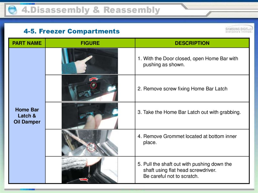
1. With the Door closed, open Home Bar with
pushing as shown.
2. Remove screw fixing Home Bar Latch
Home Bar
Latch &
Oil Damper
3. Take the Home Bar Latch out with grabbing.
4. Remove Grommet located at bottom inner
place.
5. Pull the shaft out with pushing down the
shaft using flat head screwdriver.
Be careful not to scratch.
72.
4.Disassembly & Reassembly4-5. Freezer Compartments
PART NAME
FIGURE
DESCRIPTION
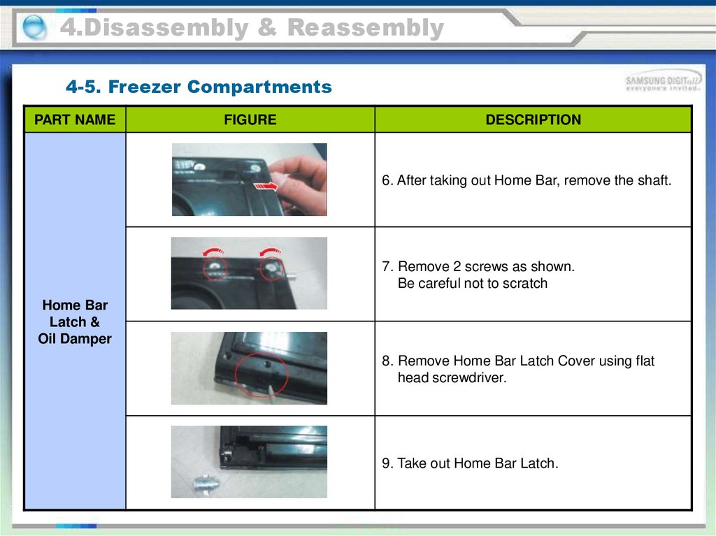
6. After taking out Home Bar, remove the shaft.
7. Remove 2 screws as shown.
Be careful not to scratch
Home Bar
Latch &
Oil Damper
8. Remove Home Bar Latch Cover using flat
head screwdriver.
9. Take out Home Bar Latch.
73.
4.Disassembly & Reassembly4-6. Fridge Door
PART NAME
FIGURE
DESCRIPTION
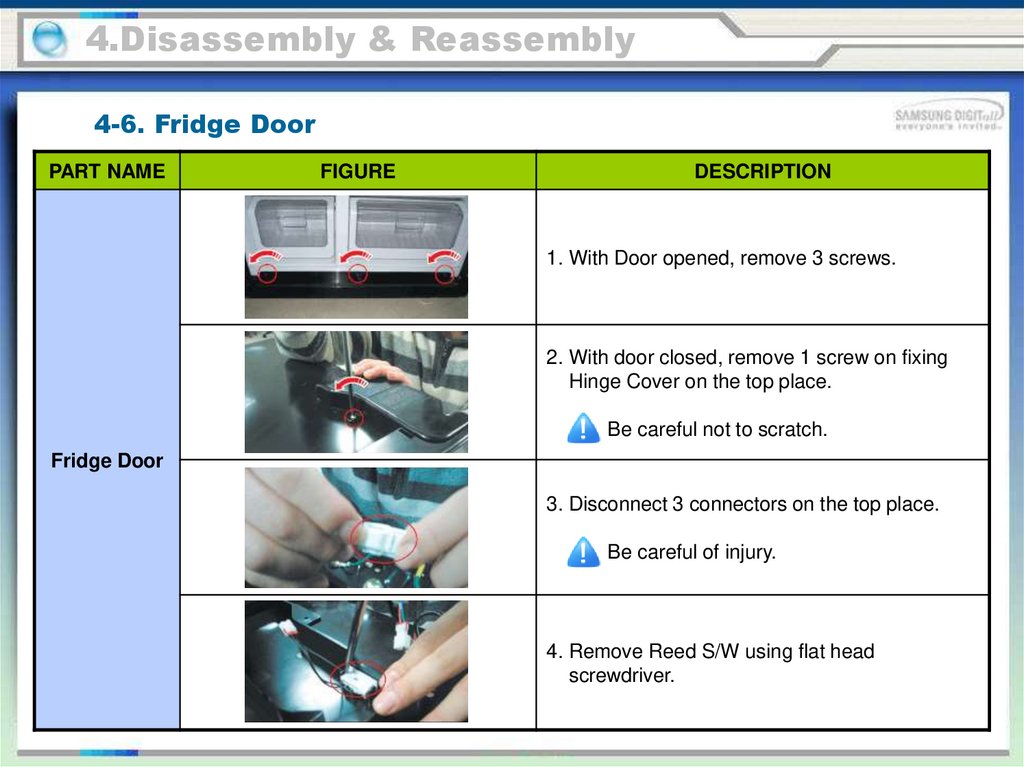
1. With Door opened, remove 3 screws.
2. With door closed, remove 1 screw on fixing
Hinge Cover on the top place.
Be careful not to scratch.
Fridge Door
3. Disconnect 3 connectors on the top place.
Be careful of injury.
4. Remove Reed S/W using flat head
screwdriver.
74.
4.Disassembly & Reassembly4-6. Fridge Door
PART NAME
FIGURE
DESCRIPTION
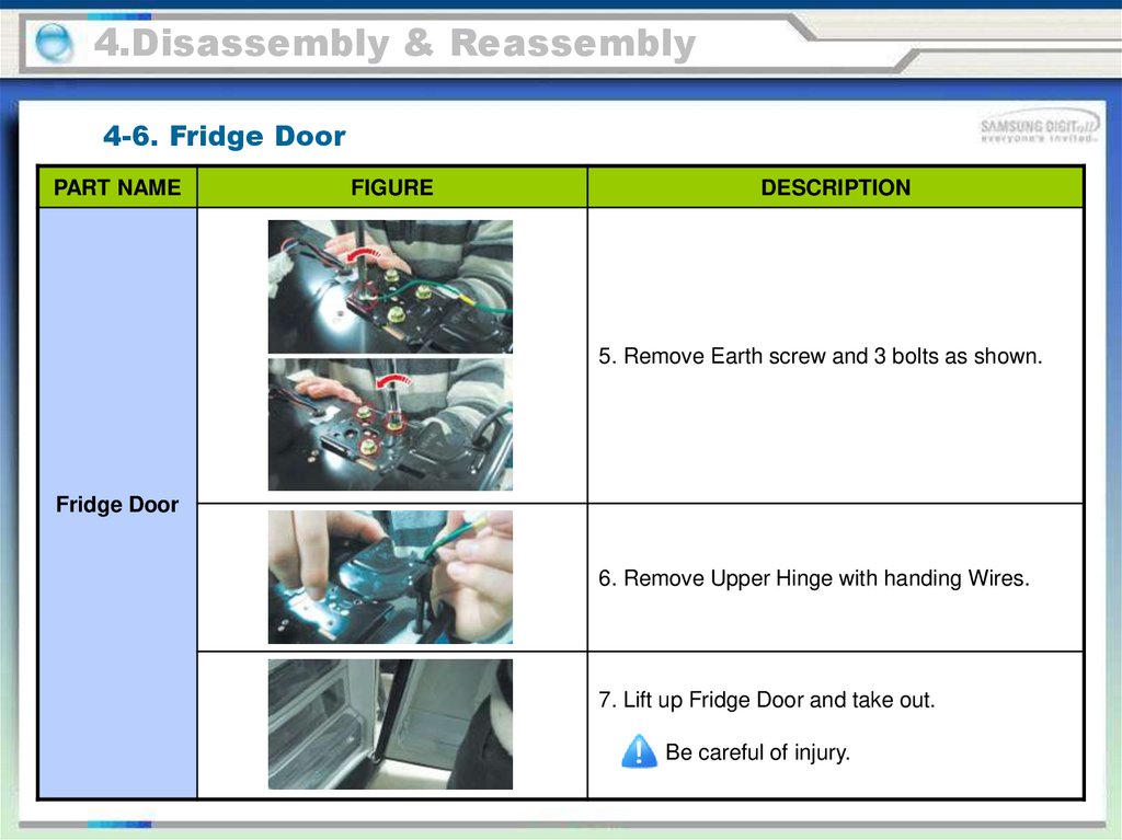
5. Remove Earth screw and 3 bolts as shown.
Fridge Door
6. Remove Upper Hinge with handing Wires.
7. Lift up Fridge Door and take out.
Be careful of injury.
75.
4.Disassembly & Reassembly4-6. Fridge Door
PART NAME
FIGURE
DESCRIPTION
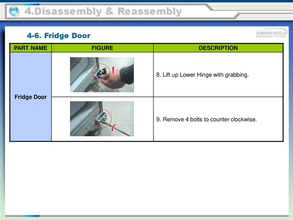
8. Lift up Lower Hinge with grabbing.
Fridge Door
9. Remove 4 bolts to counter clockwise.
76.
4.Disassembly & Reassembly4-7. Fridge Compartments
PART NAME
FIGURE
DESCRIPTION
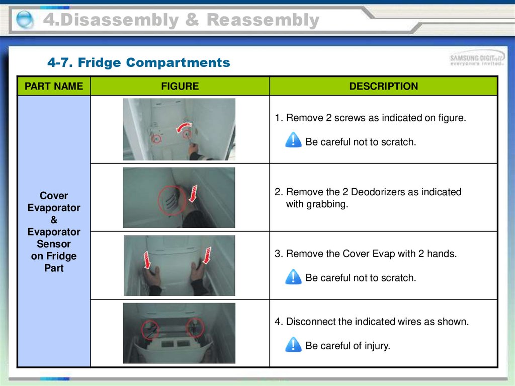
1. Remove 2 screws as indicated on figure.
Be careful not to scratch.
Cover
Evaporator
&
Evaporator
Sensor
on Fridge
Part
2. Remove the 2 Deodorizers as indicated
with grabbing.
3. Remove the Cover Evap with 2 hands.
Be careful not to scratch.
4. Disconnect the indicated wires as shown.
Be careful of injury.
77.
4.Disassembly & Reassembly4-7. Fridge Compartments
PART NAME
Cover
Evaporator
&
Evaporator
Sensor
on Fridge
Part
FIGURE
DESCRIPTION
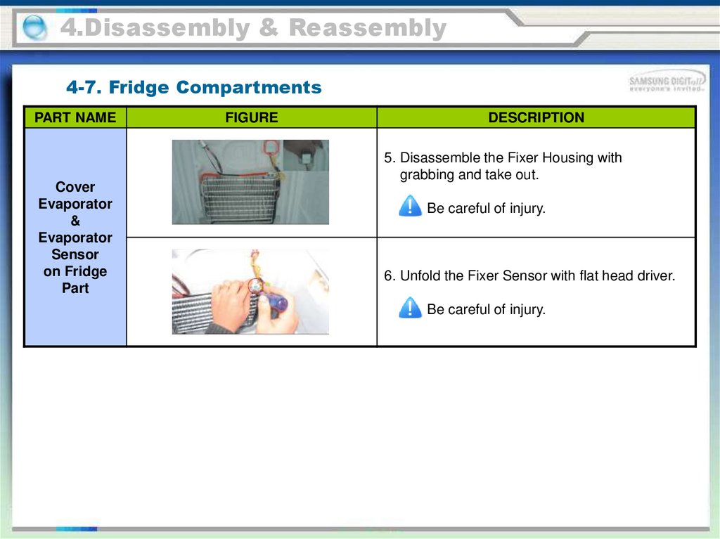
5. Disassemble the Fixer Housing with
grabbing and take out.
Be careful of injury.
6. Unfold the Fixer Sensor with flat head driver.
Be careful of injury.
78.
4.Disassembly & Reassembly4-7. Fridge Compartments
PART NAME
FIGURE
DESCRIPTION
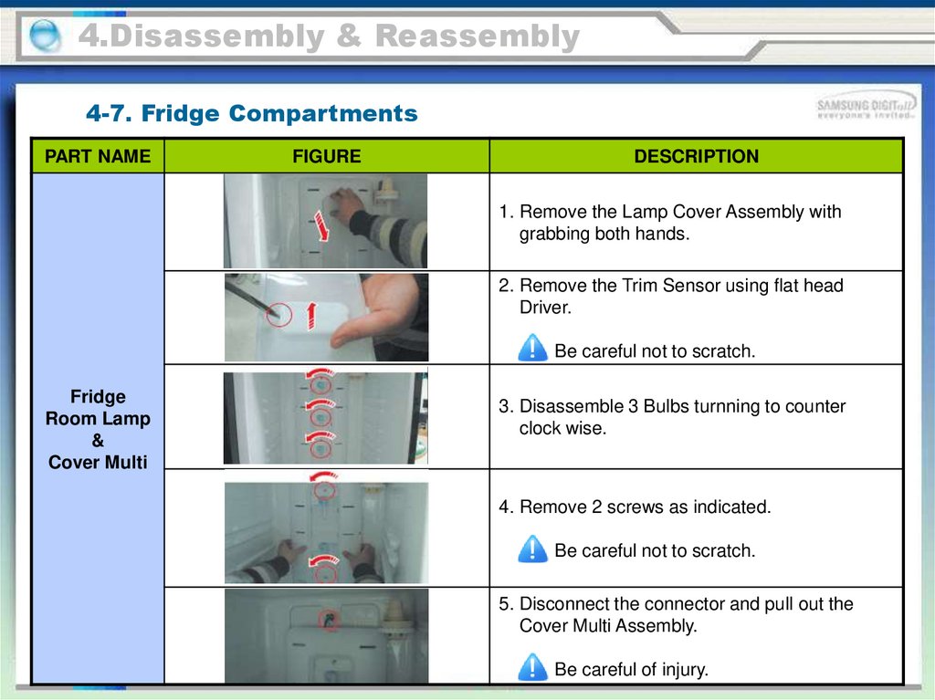
1. Remove the Lamp Cover Assembly with
grabbing both hands.
2. Remove the Trim Sensor using flat head
Driver.
Be careful not to scratch.
Fridge
Room Lamp
&
Cover Multi
3. Disassemble 3 Bulbs turnning to counter
clock wise.
4. Remove 2 screws as indicated.
Be careful not to scratch.
5. Disconnect the connector and pull out the
Cover Multi Assembly.
Be careful of injury.
79.
4.Disassembly & Reassembly4-7. Fridge Compartments
PART NAME
Fridge
Shelves
Movable
Tray
Z Shelf
Water Filter
FIGURE
DESCRIPTION
These shelves allow the storage of larger items
and pull out for easy access.
Lift it up and pull the Shelves out to the front.
This Movable Shelf is designed for moving
with foods easily.
Lift it up and pull the Movable Shelf out to
the front.
This Z Shelf is designed for all kinds of wines
and bottles.
Lift it up and pull the Z Shelf out to the front.
Turn the Water Filter to the clock wise and
take out.
Be careful of injury.
80.
4.Disassembly & Reassembly4-7. Fridge Compartments
PART NAME
FIGURE
DESCRIPTION
Drawers are designed for storage of fruits,
vegetables, and deli items.The drawers are
located in the lower portion of the
refrigerator.
Fridge
Drawers
1. Pull out the drawer as far as it goes.
2. Tilt the drawer up and pull it out until it is
removed.
be careful not to damage the product.
81.
4.Disassembly & Reassembly4-7. Fridge Compartments
PART NAME
Fridge Dairy
& Door Bins
FIGURE
DESCRIPTION
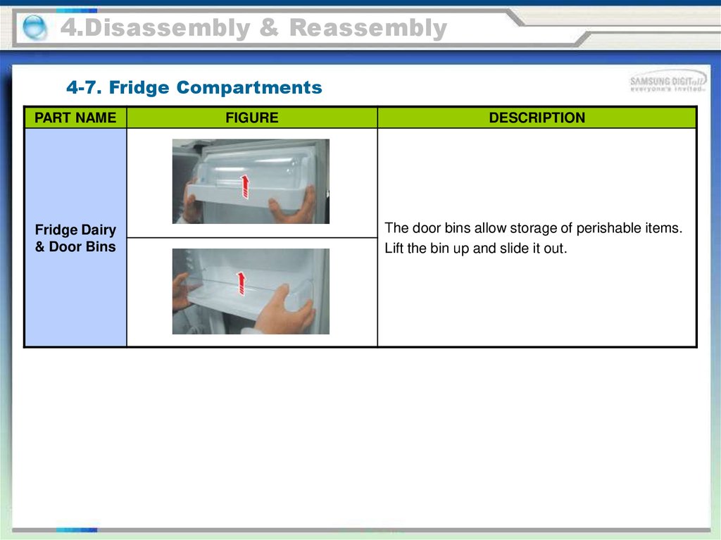
The door bins allow storage of perishable items.
Lift the bin up and slide it out.
82.
4.Disassembly & Reassembly4-7. Fridge Compartments
PART NAME
FIGURE
DESCRIPTION
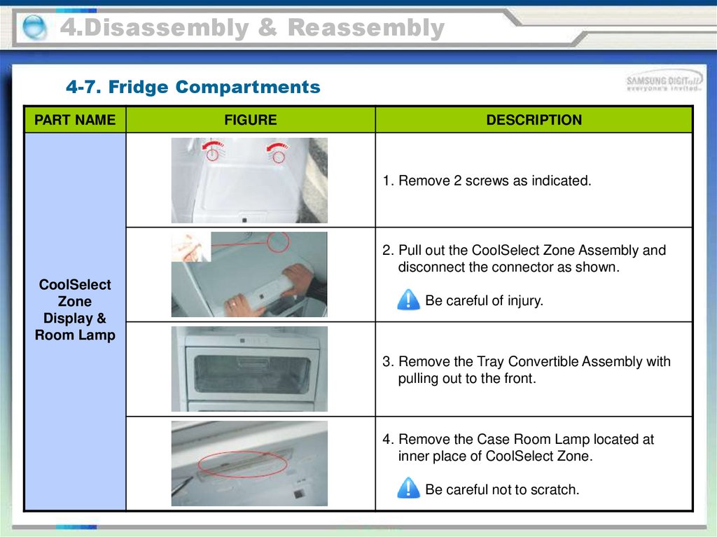
1. Remove 2 screws as indicated.
2. Pull out the CoolSelect Zone Assembly and
disconnect the connector as shown.
CoolSelect
Zone
Display &
Room Lamp
Be careful of injury.
3. Remove the Tray Convertible Assembly with
pulling out to the front.
4. Remove the Case Room Lamp located at
inner place of CoolSelect Zone.
Be careful not to scratch.
83.
4.Disassembly & Reassembly4-7. Fridge Compartments
PART NAME
FIGURE
DESCRIPTION
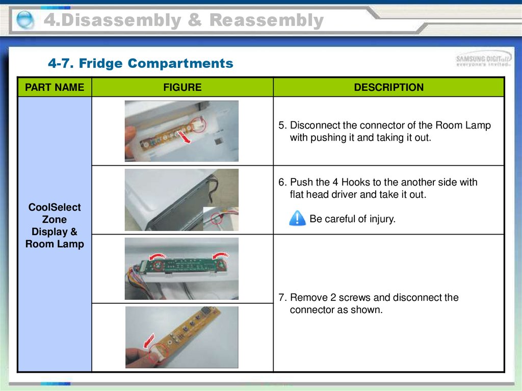
5. Disconnect the connector of the Room Lamp
with pushing it and taking it out.
6. Push the 4 Hooks to the another side with
flat head driver and take it out.
CoolSelect
Zone
Display &
Room Lamp
Be careful of injury.
7. Remove 2 screws and disconnect the
connector as shown.
84.
4.Disassembly & Reassembly4-8. Main PBA
PART NAME
FIGURE
DESCRIPTION
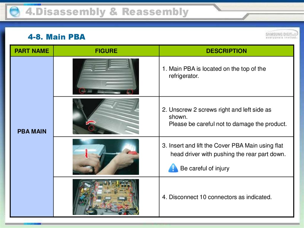
1. Main PBA is located on the top of the
refrigerator.
2. Unscrew 2 screws right and left side as
shown.
Please be careful not to damage the product.
PBA MAIN
3. Insert and lift the Cover PBA Main using flat
head driver with pushing the rear part down.
Be careful of injury
4. Disconnect 10 connectors as indicated.
85.
4.Disassembly & Reassembly4-8. Main PBA
PART NAME
FIGURE
DESCRIPTION
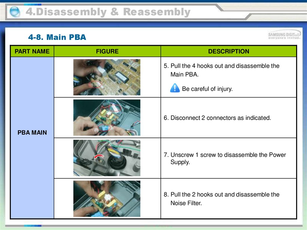
5. Pull the 4 hooks out and disassemble the
Main PBA.
Be careful of injury.
6. Disconnect 2 connectors as indicated.
PBA MAIN
7. Unscrew 1 screw to disassemble the Power
Supply.
8. Pull the 2 hooks out and disassemble the
Noise Filter.
86.
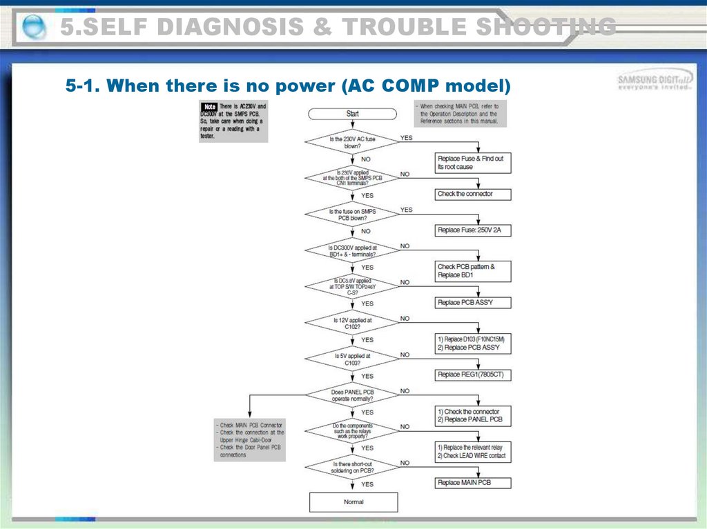
5.SELF DIAGNOSIS & TROUBLE SHOOTING5-1. When there is no power (AC COMP model)
87.
5.SELF DIAGNOSIS & TROUBLE SHOOTING5-1. When there is no power (INVERTER COMP model)
88.
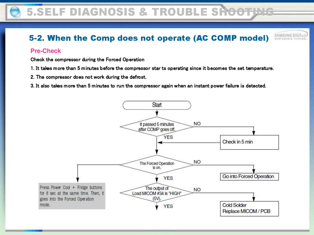
5.SELF DIAGNOSIS & TROUBLE SHOOTING5-2. When the Comp does not operate (AC COMP model)
Pre-Check
Check the compressor during the Forced Operation
1. It takes more than 5 m inutes before the compressor star ts operating since it becomes the set temperature.
2. The compressor does not work during the defrost.
3. It also takes more than 5 m inutes to run the compressor again when an instant power failure is detected.
89.
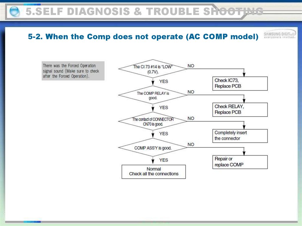
5.SELF DIAGNOSIS & TROUBLE SHOOTING5-2. When the Comp does not operate (AC COMP model)
90.
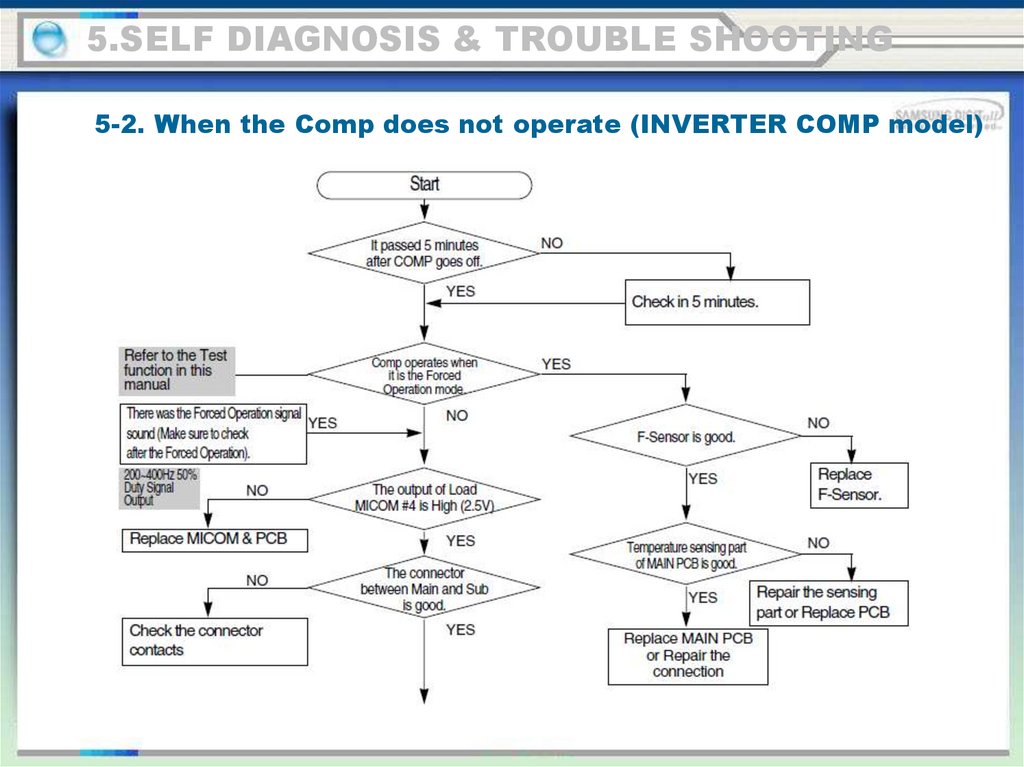
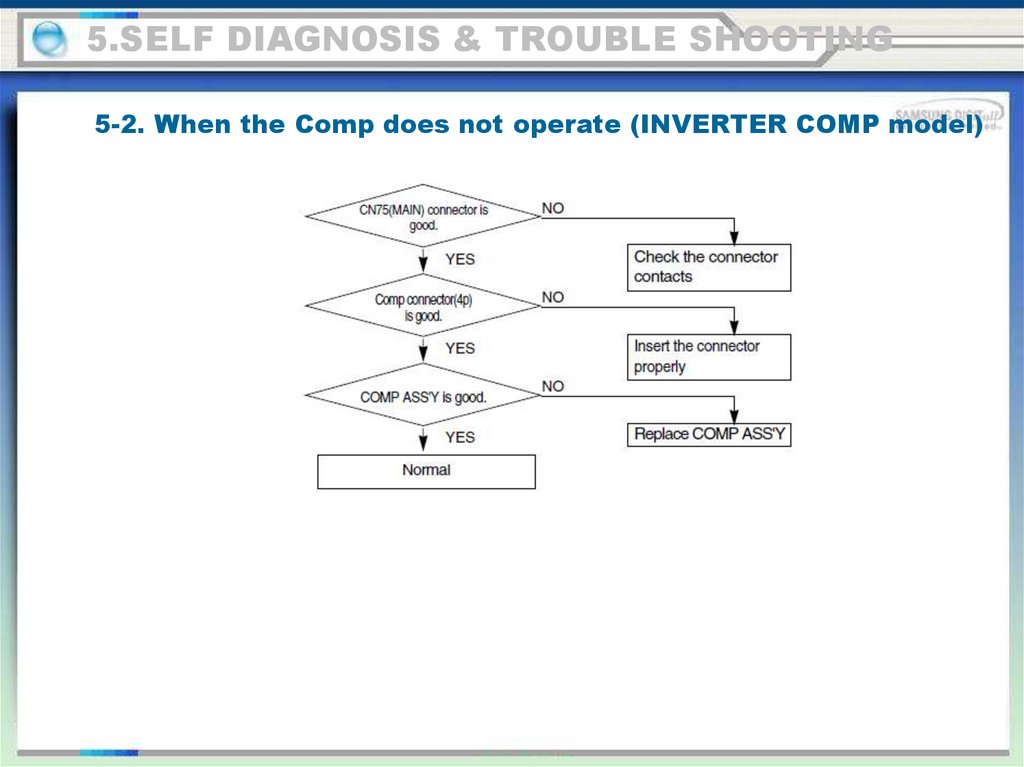
5.SELF DIAGNOSIS & TROUBLE SHOOTING5-2. When the Comp does not operate (INVERTER COMP model)
91.
5.SELF DIAGNOSIS & TROUBLE SHOOTING5-2. When the Comp does not operate (INVERTER COMP model)
92.
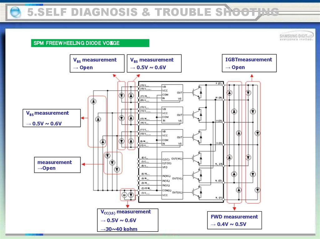
5.SELF DIAGNOSIS & TROUBLE SHOOTINGSPM FREEW HEELING DIODE VOL
A
TGE
VBS measurement
VBS measurement
IGBTmeasurement
→ Open
→ 0.5V ~ 0.6V
→ Open
VBS measurement
→ 0.5V ~ 0.6V
measurement
→Open
VCC(LS) measurement
→ 0.5V ~ 0.6V
→30~40 kohm
FWD measurement
→ 0.4V ~ 0.5V
93.
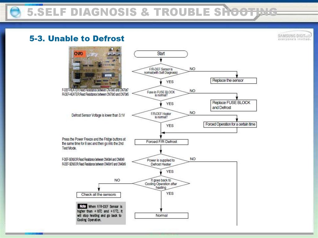
5.SELF DIAGNOSIS & TROUBLE SHOOTING5-3. Unable to Defrost
94.
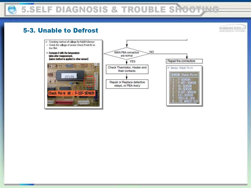
5.SELF DIAGNOSIS & TROUBLE SHOOTING5-3. Unable to Defrost
95.
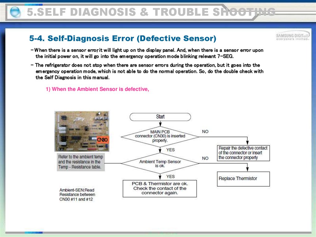
5.SELF DIAGNOSIS & TROUBLE SHOOTING5-4. Self-Diagnosis Error (Defective Sensor)
- W hen there is a sensor error, it will light up on the display panel. And, when there is a sensor error upon
the initial power on, it will go into the em ergency operation mode blinking relevant 7-SEG.
- The refrigerator does not stop when there are sensor errors during the operation, but it goes into the
em ergency operation mode, which is not able to do the normal operation. So, do the double check with
the Self Diagnosis in this manual.
1) When the Ambient Sensor is defective,
96.
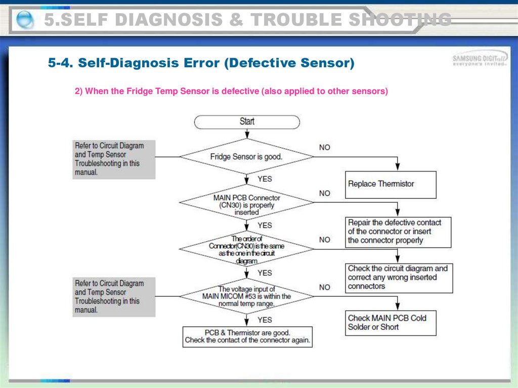
5.SELF DIAGNOSIS & TROUBLE SHOOTING5-4. Self-Diagnosis Error (Defective Sensor)
2) When the Fridge Temp Sensor is defective (also applied to other sensors)
97.
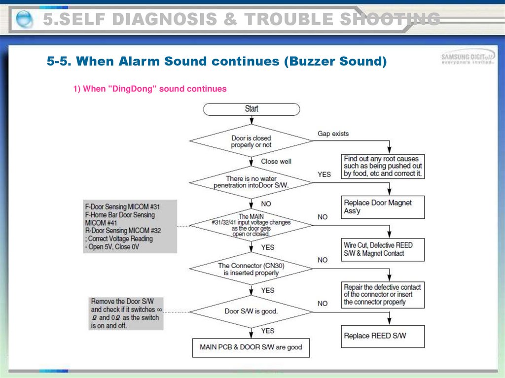
5.SELF DIAGNOSIS & TROUBLE SHOOTING5-5. When Alarm Sound continues (Buzzer Sound)
1) When "DingDong" sound continues
98.
5.SELF DIAGNOSIS & TROUBLE SHOOTING5-5. When Alarm Sound continues (Buzzer Sound)
2) When "Beeping" sounds continue
99.
5.SELF DIAGNOSIS & TROUBLE SHOOTING5-5. When Alarm Sound continues (Buzzer Sound)
3) No Buzzer Sound
This model has a buzzer affixed on the M AIN PCB.
If there is no buzzer sound upon button press, Forced Operation or Door Open, disconnect M AIN PCB and check if
the buzzer is damaged or there is any defective soldering.
(If it is not a soldering problem, it is recommended replacing M AIN PCB due to difficulties in repairing)
※ It may not be able to check when it is a closed built-in environment and there is lots of noise around.
100.
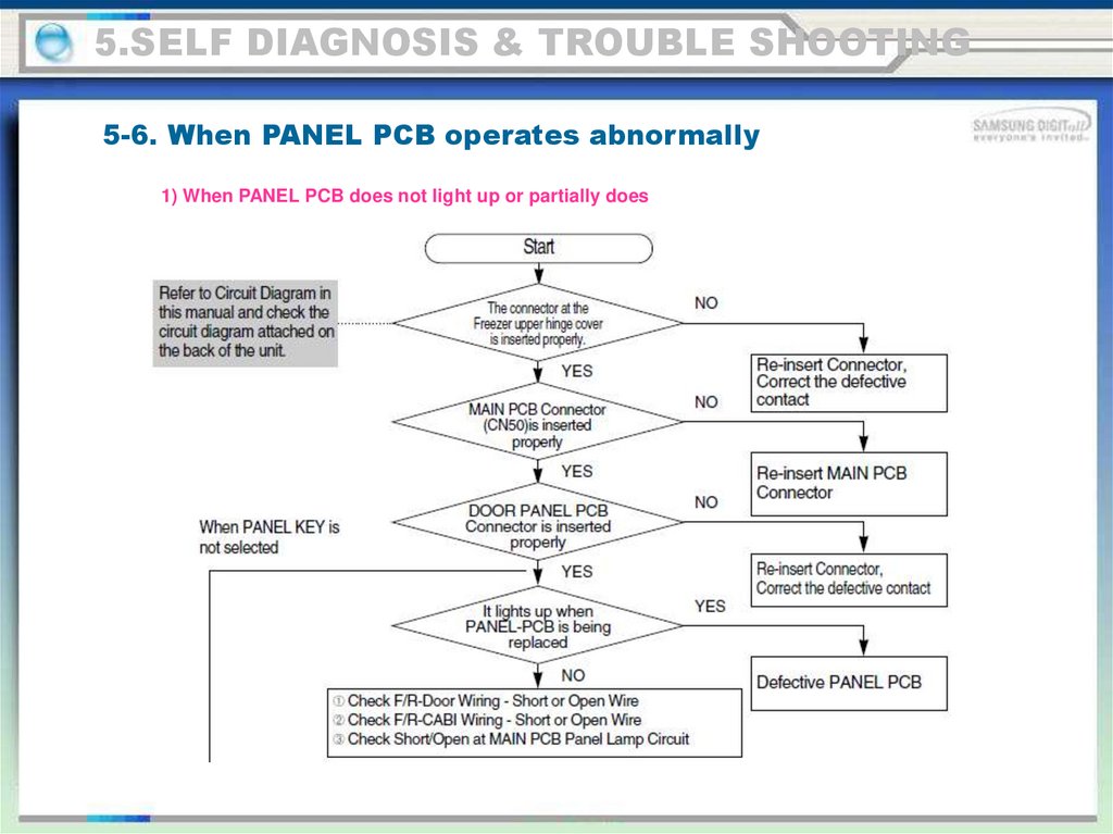
5.SELF DIAGNOSIS & TROUBLE SHOOTING5-6. When PANEL PCB operates abnormally
1) When PANEL PCB does not light up or partially does
101.
5.SELF DIAGNOSIS & TROUBLE SHOOTING5-6. When PANEL PCB operates abnormally
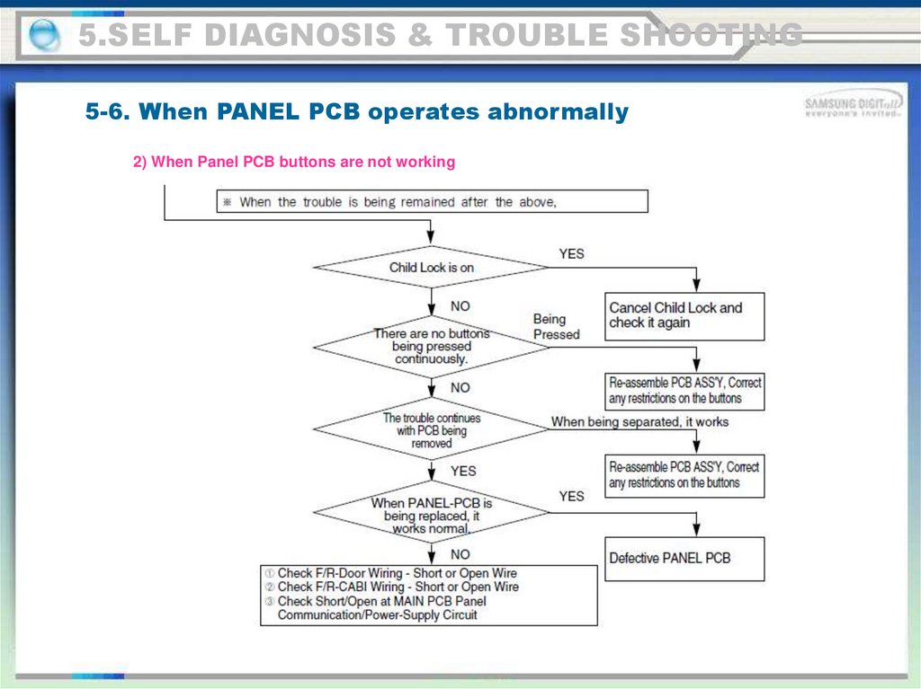
2) When Panel PCB buttons are not working
102.
5.SELF DIAGNOSIS & TROUBLE SHOOTING5-7. When Fan does not operate
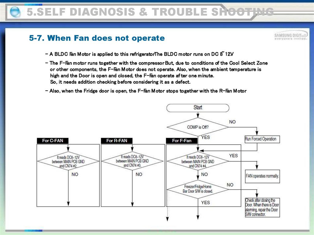
- A BLDC Fan M otor is applied to this refrigerator.The BLDC motor runs on DC 8~ 12V
.
- The F-Fan motor runs together with the compressor. But, due to conditions of the Cool Select Zone
or other components, the F-Fan M otor does not operate. Also, when the ambient temperature is
high and the Door is open and closed, the F-Fan operate af ter one minute.
So, it needs addition checking before considering it as a defect.
- Also, when the Fridge door is open, the F-Fan M otor stops together with the R-Fan M otor.
103.
5.SELF DIAGNOSIS & TROUBLE SHOOTING5-7. When Fan does not operate
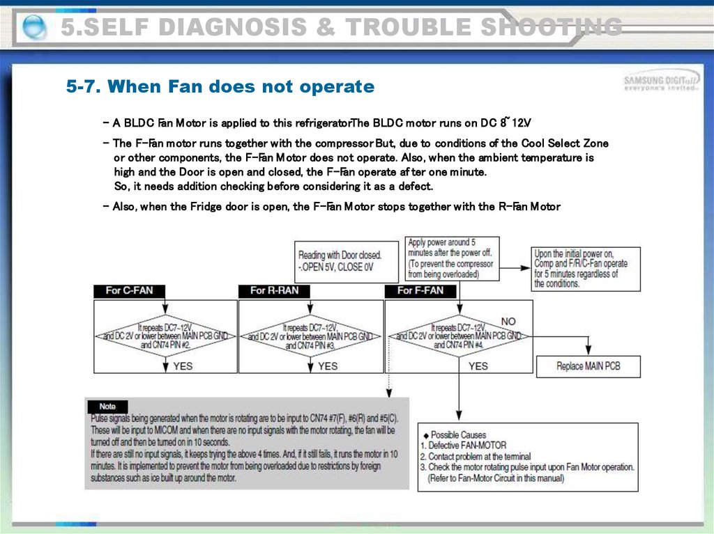
- A BLDC Fan M otor is applied to this refrigerator.The BLDC motor runs on DC 8~ 12V
.
- The F-Fan motor runs together with the compressor. But, due to conditions of the Cool Select Zone
or other components, the F-Fan M otor does not operate. Also, when the ambient temperature is
high and the Door is open and closed, the F-Fan operate af ter one minute.
So, it needs addition checking before considering it as a defect.
- Also, when the Fridge door is open, the F-Fan M otor stops together with the R-Fan M otor.
104.
5.SELF DIAGNOSIS & TROUBLE SHOOTING5-8. Freezer / Fridge Lamp does not light up
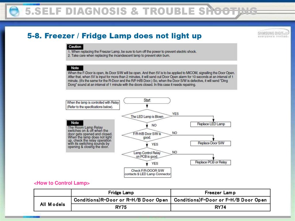
<How to Control Lamp>
All M o dels
Fridge Lamp
Co nd itio ns)R-D o o r o r R-H/B D o o r Op en
RY75
Freezer Lam p
Co nd itio ns)F-D o o r o r F-H/B D o o r Op en
RY74
105.
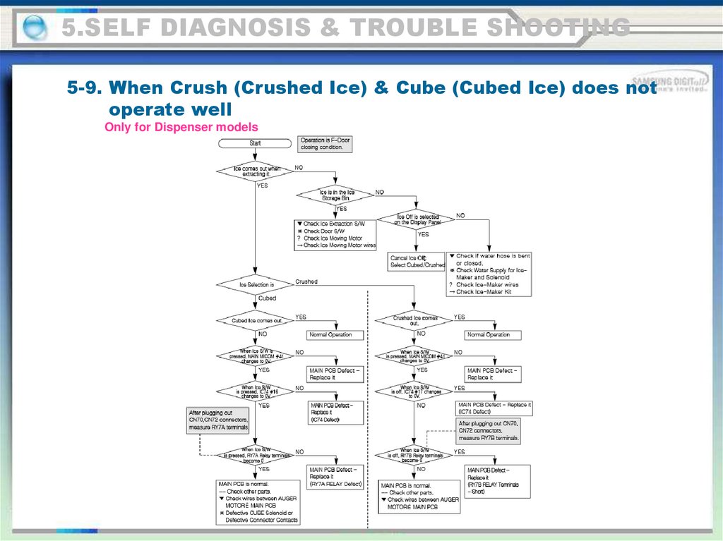
5.SELF DIAGNOSIS & TROUBLE SHOOTING5-9. When Crush (Crushed Ice) & Cube (Cubed Ice) does not
operate well
Only for Dispenser models
106.
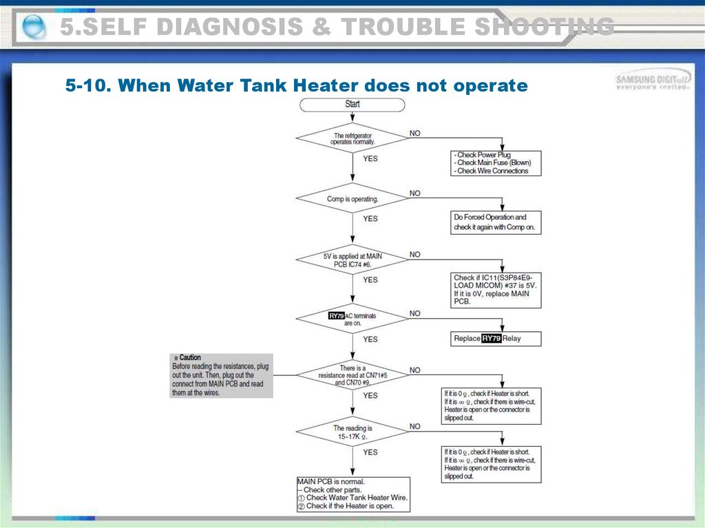
5.SELF DIAGNOSIS & TROUBLE SHOOTING5-10. When Water Tank Heater does not operate
107.
6. PCB diagram6-1. Part Arrangement (Main Board)
108.
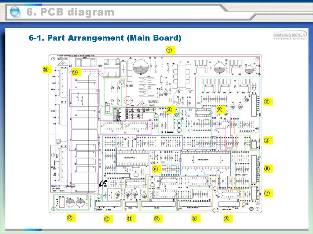
6. PCB diagram6-1. Part Arrangement (Main Board)
1. SMPS Circuit: With input AC voltage, it outputs DC12V and 5V.
2. It supplies 8.3V~10V to Deodorizer & Fan Motors.
3. Dispenser Ice & Water (Freezer Home Bar) S/W
4. Buzzer
5. EEPROM : Data Storing
6. Receives various sensor voltages and door operation signals, and filter their noises.
Then, send them to MICOM.
7. PLC Circuit (PLC Input/Output) - PLC (Power Line communication)
8. Cool Select Zone Damper and its Heater/LED
9. Cool Select Zone Display Driver :LED Display, Button Signalling
10. Display Control (MAIN ➝ PANEL PCB)
11. Step-Valve Control (3-Way Valve)
12. Ice-Maker Kit Control
13. PCB & Inverter Comp Driver: DC12V, 5V and GND are input (Applied to Inverter Model).
14. AC Load Control Relay - It operates with Micom driving signals being receipt through Sink IC.
15. AC Load Connector
a. Diode Option Setting
109.
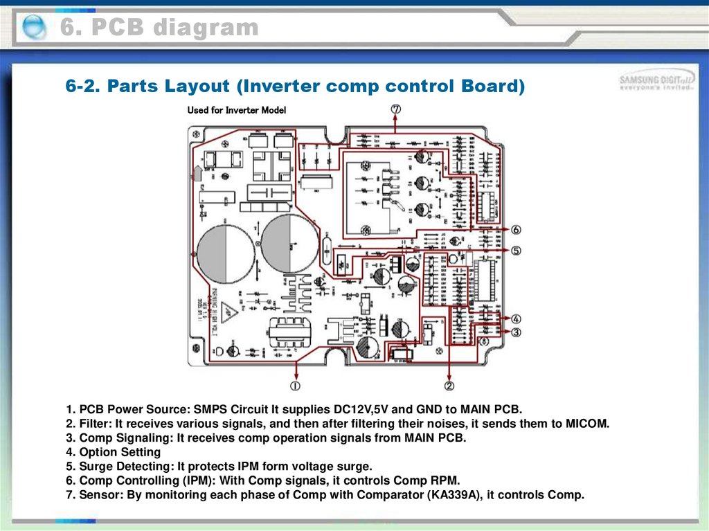
6. PCB diagram6-2. Parts Layout (Inverter comp control Board)
Used for Inverter Model
1. PCB Power Source: SMPS Circuit It supplies DC12V,5V and GND to MAIN PCB.
2. Filter: It receives various signals, and then after filtering their noises, it sends them to MICOM.
3. Comp Signaling: It receives comp operation signals from MAIN PCB.
4. Option Setting
5. Surge Detecting: It protects IPM form voltage surge.
6. Comp Controlling (IPM): With Comp signals, it controls Comp RPM.
7. Sensor: By monitoring each phase of Comp with Comparator (KA339A), it controls Comp.
110.
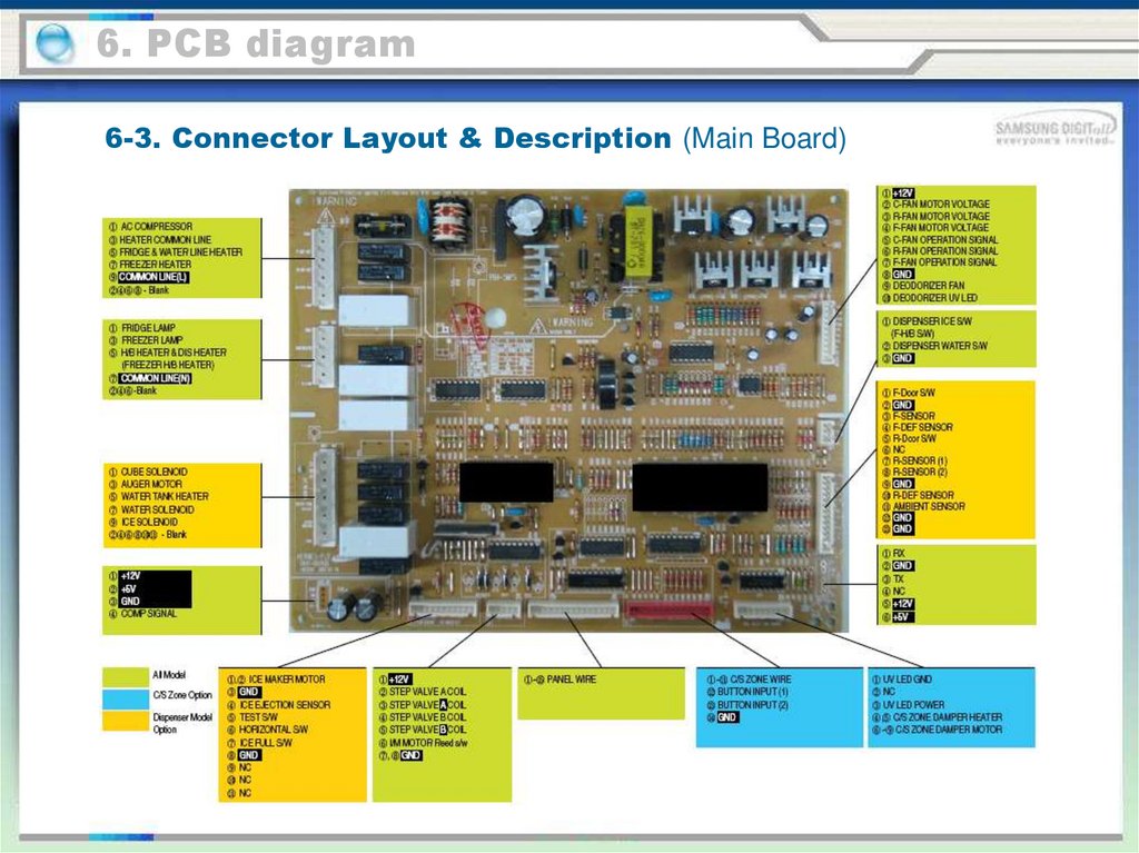
6. PCB diagram6-3. Connector Layout & Description (Main Board)
111.
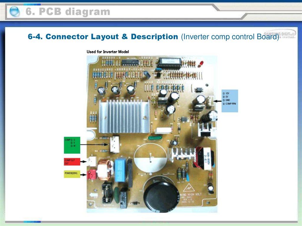
6. PCB diagram6-4. Connector Layout & Description (Inverter comp control Board)
Used for Inverter Model
112.
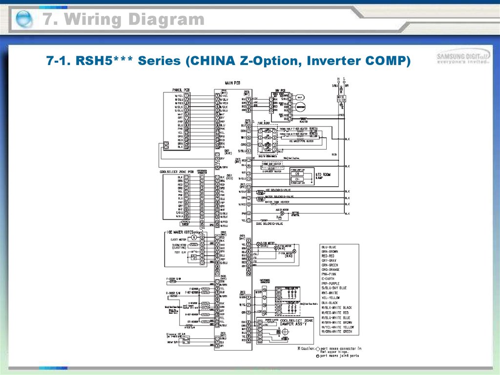
7. Wiring Diagram7-1. RSH5*** Series (CHINA Z-Option, Inverter COMP)
113.
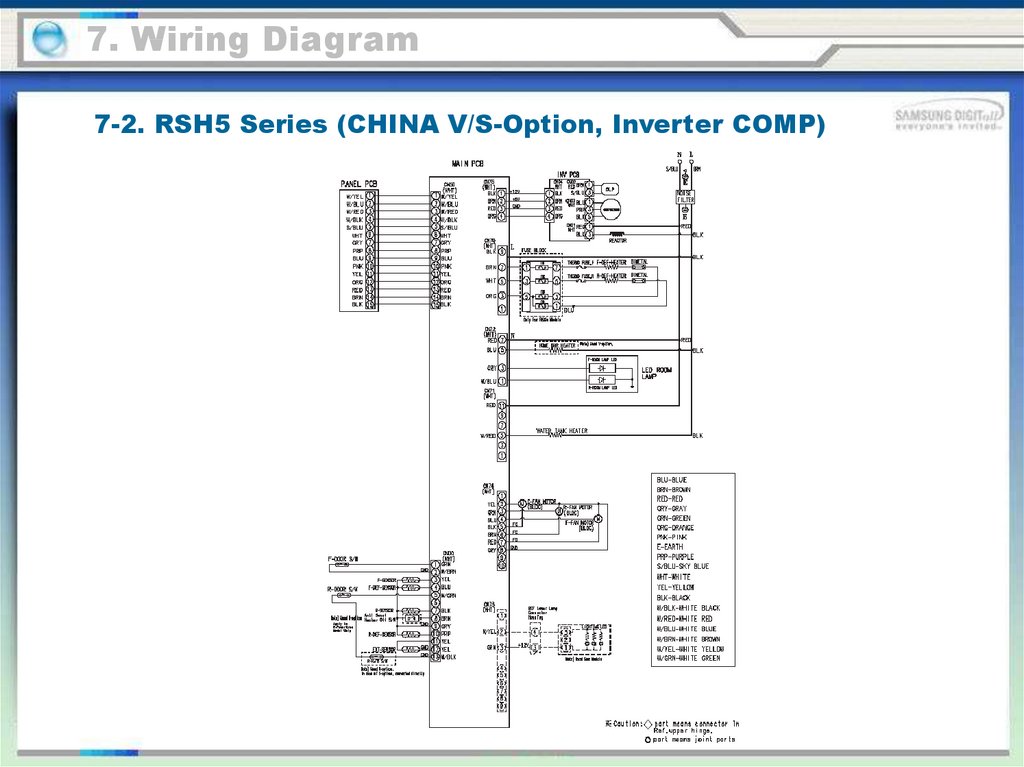
7. Wiring Diagram7-2. RSH5 Series (CHINA V/S-Option, Inverter COMP)
114.
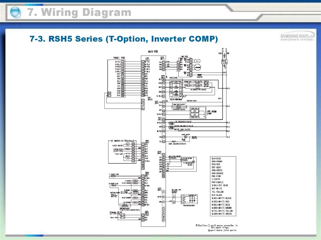
7. Wiring Diagram7-3. RSH5 Series (T-Option, Inverter COMP)
115.
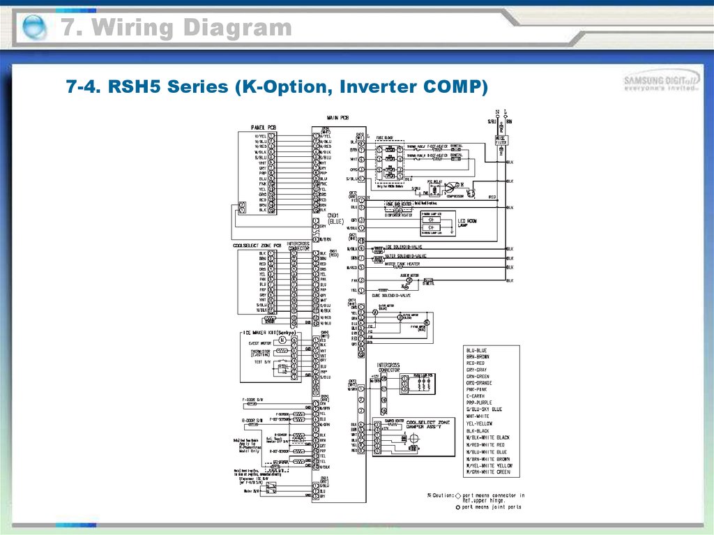
7. Wiring Diagram7-4. RSH5 Series (K-Option, Inverter COMP)
116.
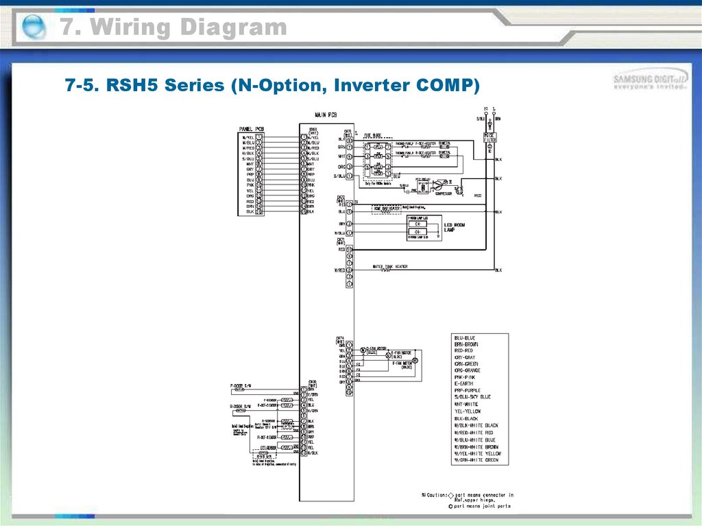
7. Wiring Diagram7-5. RSH5 Series (N-Option, Inverter COMP)
117.
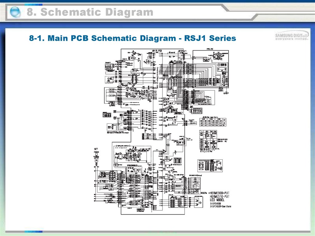
8. Schematic Diagram8-1. Main PCB Schematic Diagram - RSJ1 Series
118.
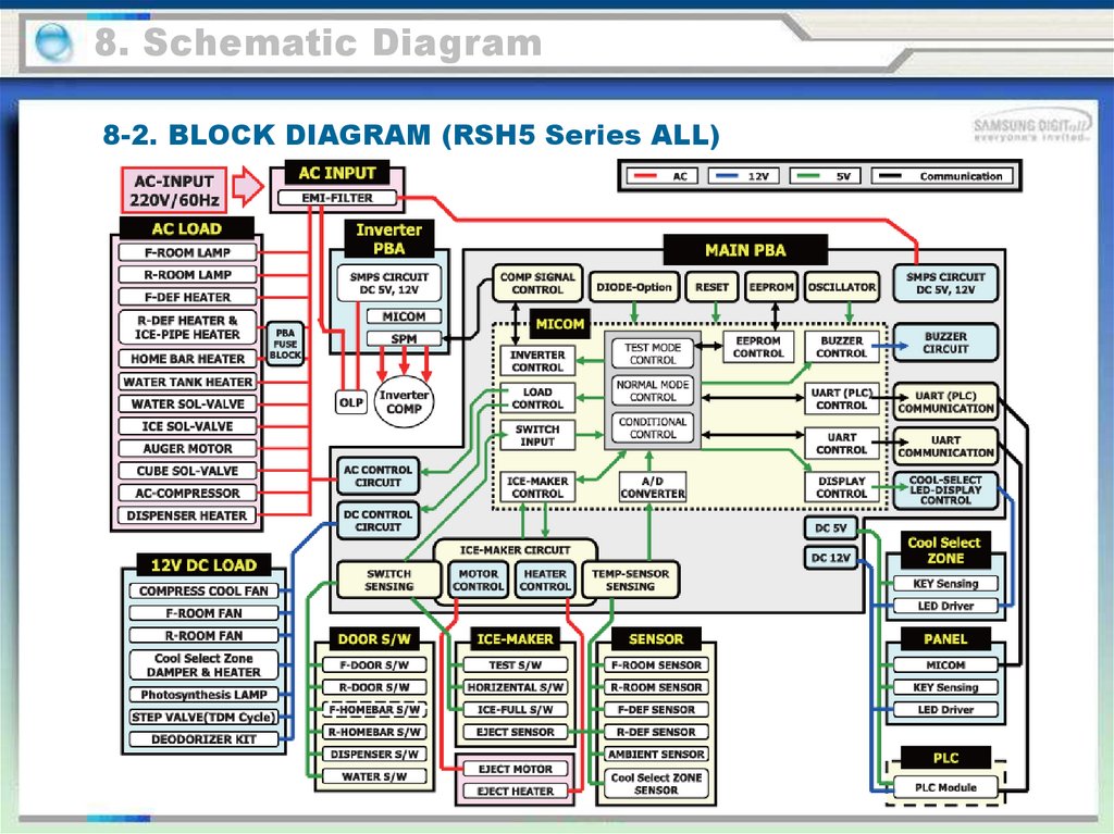
8. Schematic Diagram8-2. BLOCK DIAGRAM (RSH5 Series ALL)
119.
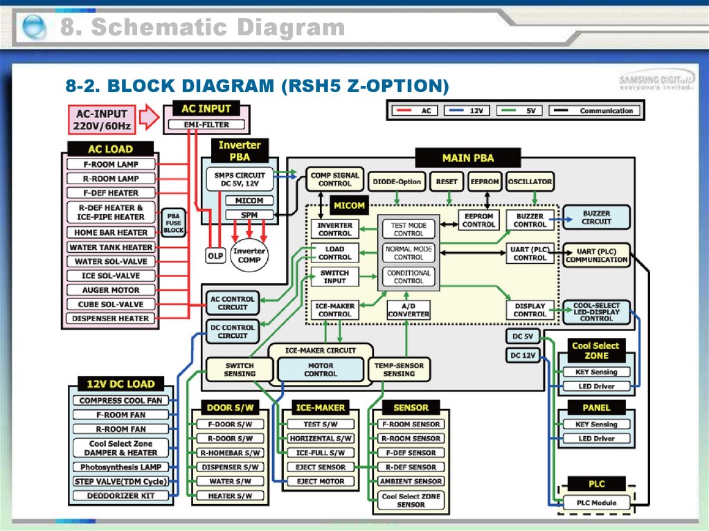
8. Schematic Diagram8-2. BLOCK DIAGRAM (RSH5 Z-OPTION)
120.
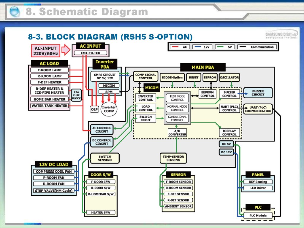
8. Schematic Diagram8-3. BLOCK DIAGRAM (RSH5 S-OPTION)
121.
8. Schematic Diagram8-4. BLOCK DIAGRAM (RSH5 T/R-OPTION)
122.
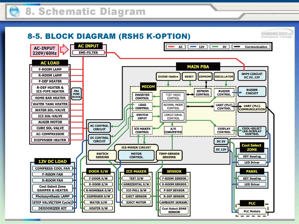
8. Schematic Diagram8-5. BLOCK DIAGRAM (RSH5 K-OPTION)
123.
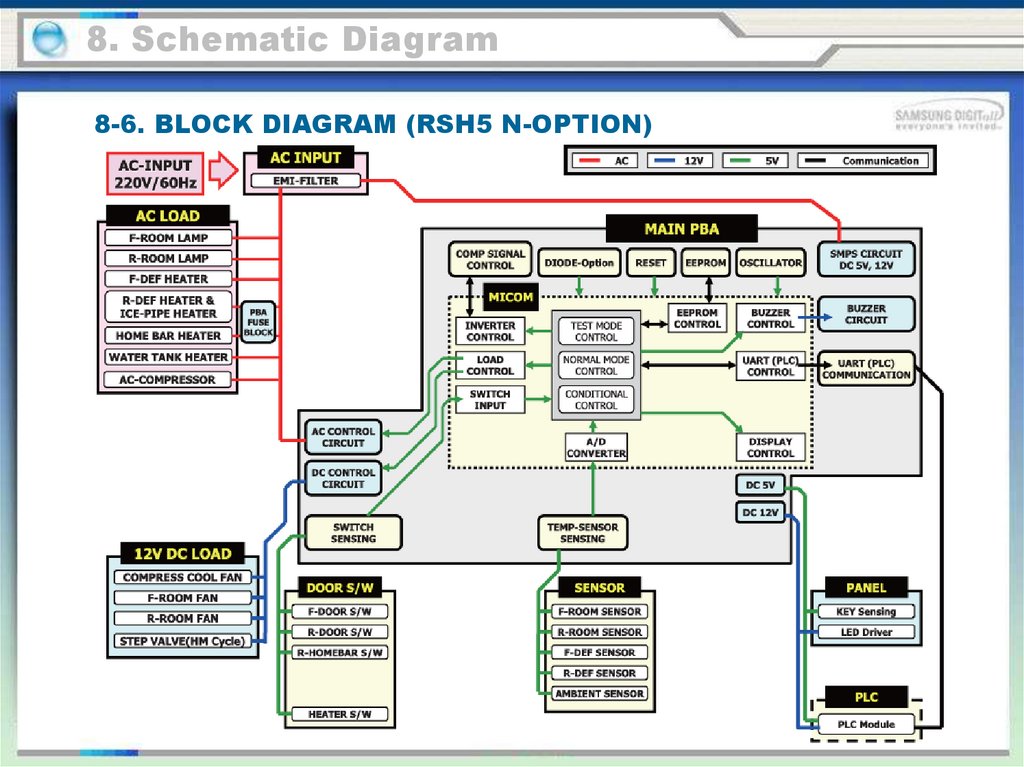
8. Schematic Diagram8-6. BLOCK DIAGRAM (RSH5 N-OPTION)
124.
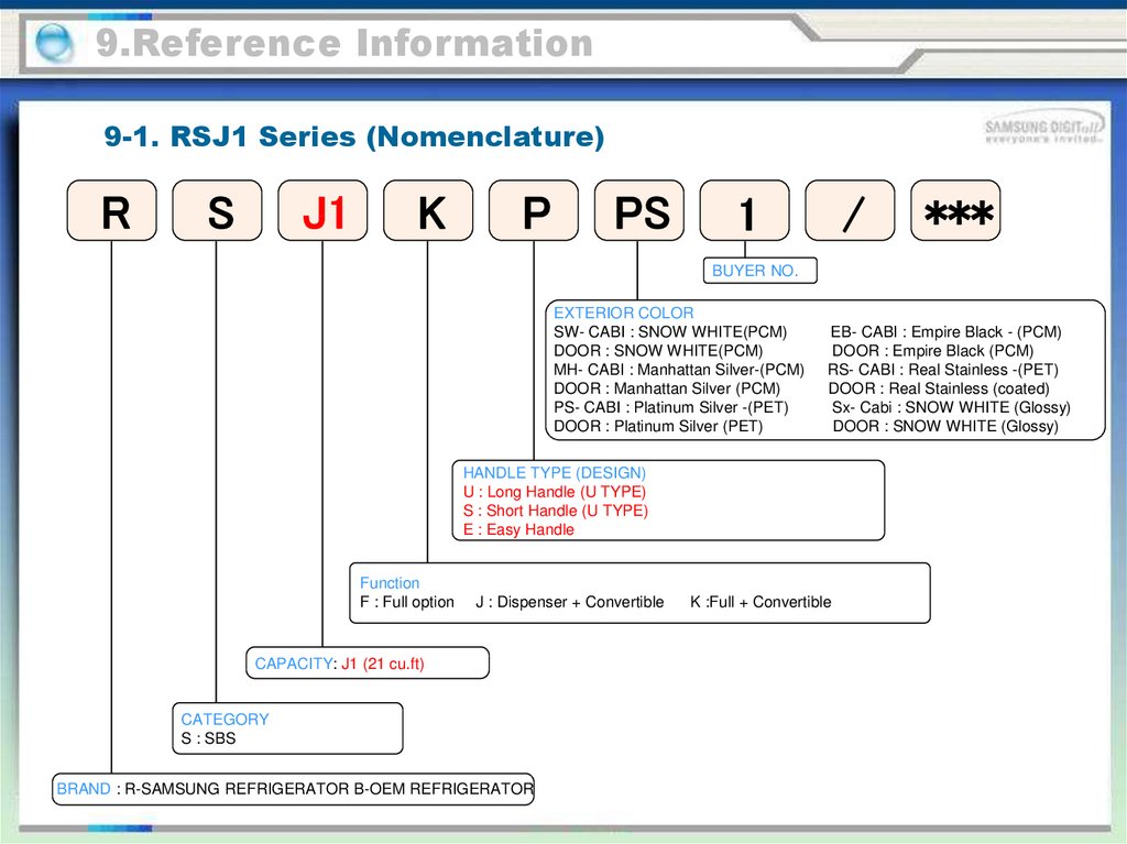
9.Reference Information9-1. RSJ1 Series (Nomenclature)
R
S
J1
K
P
PS
1
/
***
BUYER NO.
EXTERIOR COLOR
SW- CABI : SNOW WHITE(PCM)
DOOR : SNOW WHITE(PCM)
MH- CABI : Manhattan Silver-(PCM)
DOOR : Manhattan Silver (PCM)
PS- CABI : Platinum Silver -(PET)
DOOR : Platinum Silver (PET)
EB- CABI : Empire Black - (PCM)
DOOR : Empire Black (PCM)
RS- CABI : Real Stainless -(PET)
DOOR : Real Stainless (coated)
Sx- Cabi : SNOW WHITE (Glossy)
DOOR : SNOW WHITE (Glossy)
HANDLE TYPE (DESIGN)
U : Long Handle (U TYPE)
S : Short Handle (U TYPE)
E : Easy Handle
Function
F : Full option
J : Dispenser + Convertible
CAPACITY: J1 (21 cu.ft)
CATEGORY
S : SBS
BRAND : R-SAMSUNG REFRIGERATOR B-OEM REFRIGERATOR
K :Full + Convertible
125.
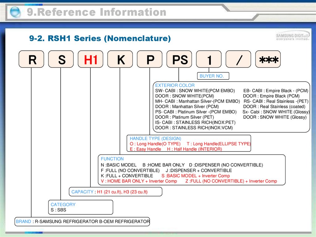
9.Reference Information9-2. RSH1 Series (Nomenclature)
R
S
H1
K
P
PS
1
***
/
BUYER NO.
EXTERIOR COLOR
SW- CABI : SNOW WHITE(PCM EMBO)
DOOR : SNOW WHITE(PCM)
MH- CABI : Manhattan Silver-(PCM EMBO)
DOOR : Manhattan Silver (PCM)
PS- CABI : Platinum Silver -(PCM EMBO)
DOOR : Platinum Silver (PET)
IS- CABI : STAINLESS RICH(INOX:PET)
DOOR : STAINLESS RICH(INOX:VCM)
EB- CABI : Empire Black - (PCM)
DOOR : Empire Black (PCM)
RS- CABI : Real Stainless -(PET)
DOOR : Real Stainless (coated)
Sx- Cabi : SNOW WHITE (Glossy)
DOOR : SNOW WHITE (Glossy)
HANDLE TYPE (DESIGN)
O : Long Handle(O TYPE) T : Long Handle(ELLIPSE TYPE)
E : Easy Handle H : Half Handle (INTERIOR)
FUNCTION
N :BASIC MODEL B :HOME BAR ONLY D :DISPENSER (NO CONVERTIBLE)
F :FULL (NO CONVERTIBLE) J :DISPENSER + CONVERTIBLE
K :FULL + CONVERTIBLE
S :BASIC MODEL + Inverter Comp
V : HOME BAR ONLY + Inverter Comp
Z :FULL (NO CONVERTIBLE) + Inverter Comp
CAPACITY : H1 (21 cu.ft), H3 (23 cu.ft)
CATEGORY
S : SBS
BRAND : R-SAMSUNG REFRIGERATOR B-OEM REFRIGERATOR
126.
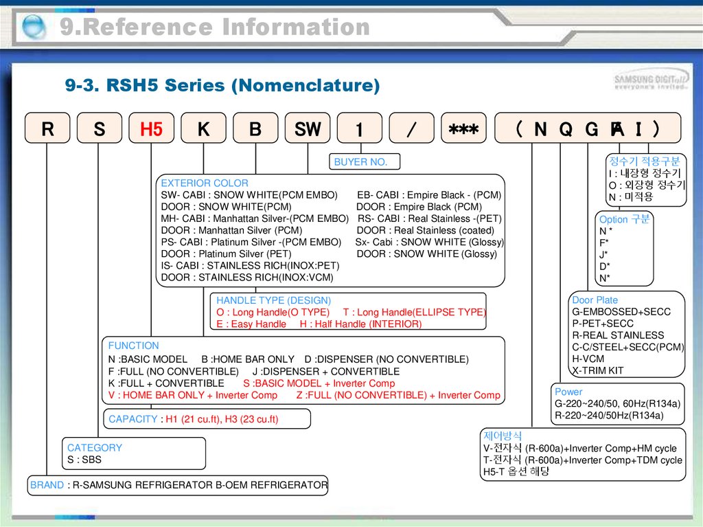
9.Reference Information9-3. RSH5 Series (Nomenclature)
R
S
H5
K
B
SW
1
/
***
( N Q G FA I )
BUYER NO.
EXTERIOR COLOR
SW- CABI : SNOW WHITE(PCM EMBO)
DOOR : SNOW WHITE(PCM)
MH- CABI : Manhattan Silver-(PCM EMBO)
DOOR : Manhattan Silver (PCM)
PS- CABI : Platinum Silver -(PCM EMBO)
DOOR : Platinum Silver (PET)
IS- CABI : STAINLESS RICH(INOX:PET)
DOOR : STAINLESS RICH(INOX:VCM)
EB- CABI : Empire Black - (PCM)
DOOR : Empire Black (PCM)
RS- CABI : Real Stainless -(PET)
DOOR : Real Stainless (coated)
Sx- Cabi : SNOW WHITE (Glossy)
DOOR : SNOW WHITE (Glossy)
HANDLE TYPE (DESIGN)
O : Long Handle(O TYPE) T : Long Handle(ELLIPSE TYPE)
E : Easy Handle H : Half Handle (INTERIOR)
FUNCTION
N :BASIC MODEL B :HOME BAR ONLY D :DISPENSER (NO CONVERTIBLE)
F :FULL (NO CONVERTIBLE) J :DISPENSER + CONVERTIBLE
K :FULL + CONVERTIBLE
S :BASIC MODEL + Inverter Comp
V : HOME BAR ONLY + Inverter Comp
Z :FULL (NO CONVERTIBLE) + Inverter Comp
CAPACITY : H1 (21 cu.ft), H3 (23 cu.ft)
CATEGORY
S : SBS
BRAND : R-SAMSUNG REFRIGERATOR B-OEM REFRIGERATOR
정수기 적용구분
I : 내장형 정수기
O : 외장형 정수기
N : 미적용
Option 구분
N*
F*
J*
D*
N*
Door Plate
G-EMBOSSED+SECC
P-PET+SECC
R-REAL STAINLESS
C-C/STEEL+SECC(PCM)
H-VCM
X-TRIM KIT
Power
G-220~240/50, 60Hz(R134a)
R-220~240/50Hz(R134a)
제어방식
V-전자식 (R-600a)+Inverter Comp+HM cycle
T-전자식 (R-600a)+Inverter Comp+TDM cycle
H5-T 옵션 해당
127.
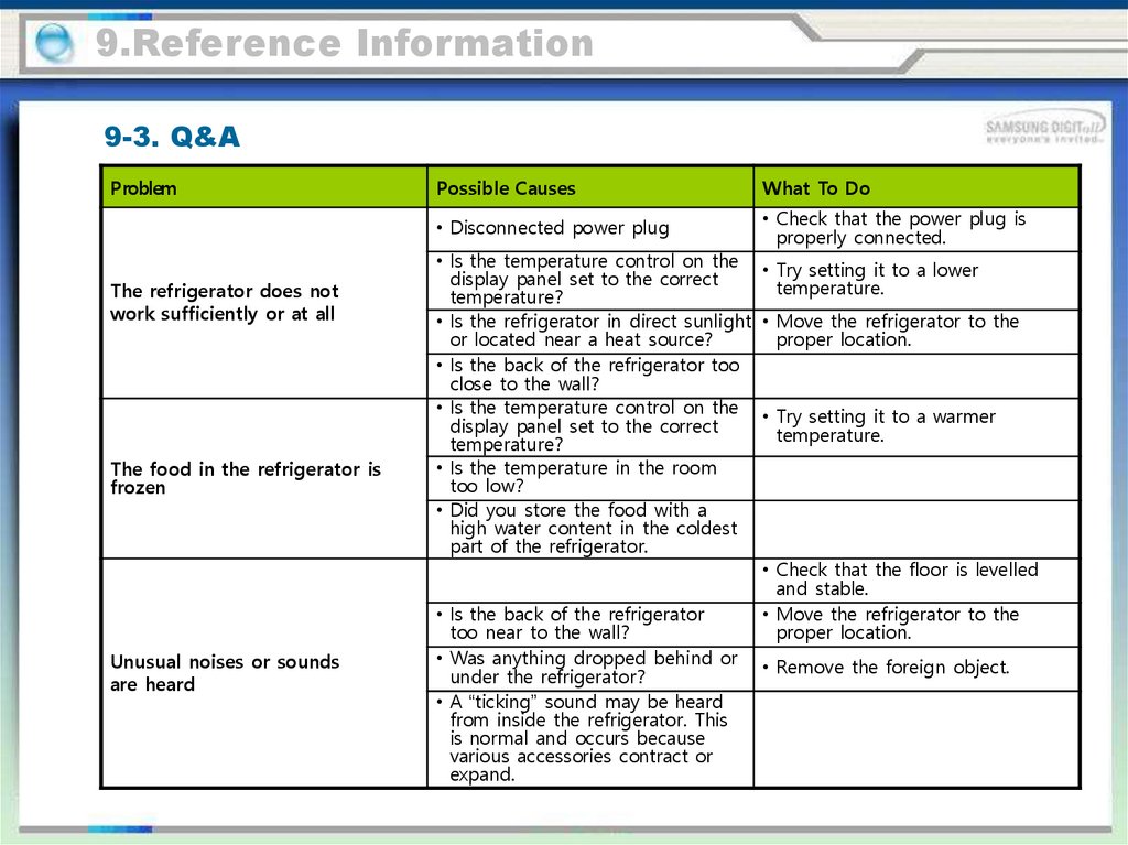
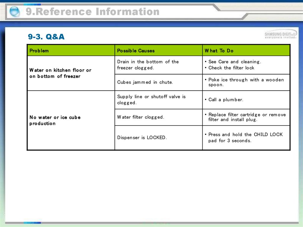
9.Reference Information9-3. Q&A
Problem
The refrigerator does not
work sufficiently or at all
The food in the refrigerator is
frozen
Unusual noises or sounds
are heard
Possible Causes
What To Do
• Disconnected power plug
• Check that the power plug is
properly connected.
• Is the temperature control on the • Try setting it to a lower
display panel set to the correct
temperature.
temperature?
• Is the refrigerator in direct sunlight • Move the refrigerator to the
or located near a heat source?
proper location.
• Is the back of the refrigerator too
close to the wall?
• Is the temperature control on the • Try setting it to a warmer
display panel set to the correct
temperature.
temperature?
• Is the temperature in the room
too low?
• Did you store the food with a
high water content in the coldest
part of the refrigerator.
• Check that the floor is levelled
and stable.
• Is the back of the refrigerator
• Move the refrigerator to the
too near to the wall?
proper location.
• Was anything dropped behind or • Remove the foreign object.
under the refrigerator?
• A “ticking” sound may be heard
from inside the refrigerator. This
is normal and occurs because
various accessories contract or
expand.
128.
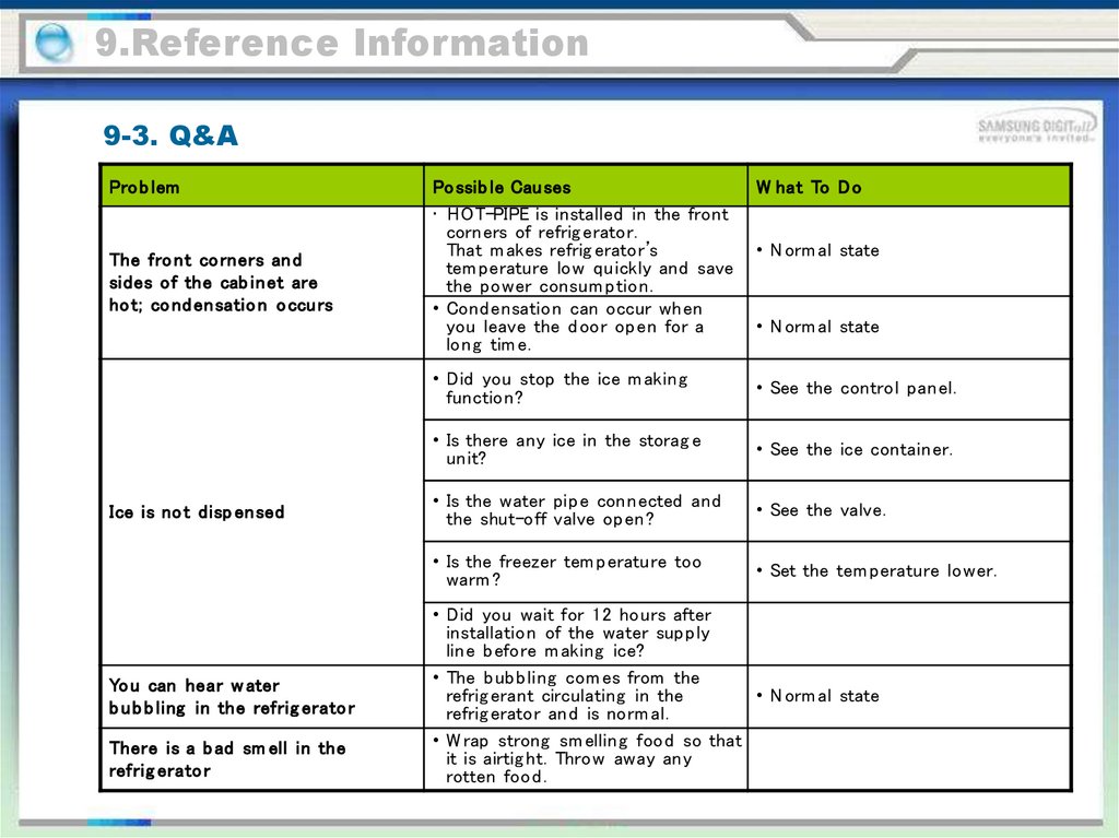
9.Reference Information9-3. Q&A
Pro b lem
The fro nt co rners an d
sides of the cab inet are
ho t; co nd ensatio n o ccu rs
Ice is no t disp ensed
Yo u can hear w ater
b u b b ling in the refrig erato r
There is a b ad sm ell in the
refrig erato r
Po ssib le Cau ses
• HOT-PIPE is installed in the front
corners of refrig erator.
That m akes refrig erator’s
tem perature low quickly and save
the po wer consum ption.
• Cond ensatio n can occur when
you leave the d oor op en for a
long tim e.
W hat To D o
• Did you stop the ice m aking
function?
• See the control panel.
• Is there any ice in the storag e
unit?
• See the ice container.
• Is the water pip e connected and
the shut-off valve op en?
• See the valve.
• Is the freezer tem perature too
warm ?
• Set the tem perature lower.
• N orm al state
• N orm al state
• Did you wait for 12 ho urs after
installation of the water sup p ly
line b efore m aking ice?
• The b ub b ling com es from the
• N orm al state
refrig erant circulating in the
refrig erator and is norm al.
• W rap strong sm elling food so that
it is airtig ht. Throw away any
rotten food .
129.
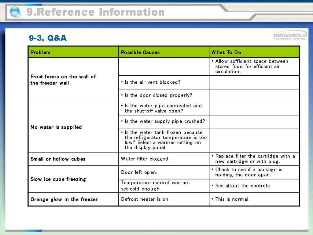
9.Reference Information9-3. Q&A
Pro b lem
Po ssib le Cau ses
W hat To D o
• Allo w sufficient space b etween
stored food for efficient air
circulation.
Fro st fo rm s o n the w all of
the freezer w all
• Is the air vent b locked ?
• Is the d oor closed pro p erly?
• Is the water pip e connected and
the shut-off valve op en?
• Is the water sup p ly pip e crushed ?
N o w ater is su p p lied
Sm all o r ho llo w cu b es
Slo w ice cu b e freezing
Orang e g lo w in the freezer
• Is the water tank frozen b ecause
the refrig erator tem perature is too
low? Select a warm er setting on
the d isplay panel.
W ater filter clog g ed .
• Replace filter the cartrid g e with a
new cartrid g e or with plug .
Door left op en.
• Check to see if a packag e is
ho ld ing the d oor op en.
Tem perature control was not
set cold eno ug h.
• See ab out the controls.
Defrost heater is on.
• This is norm al.
130.
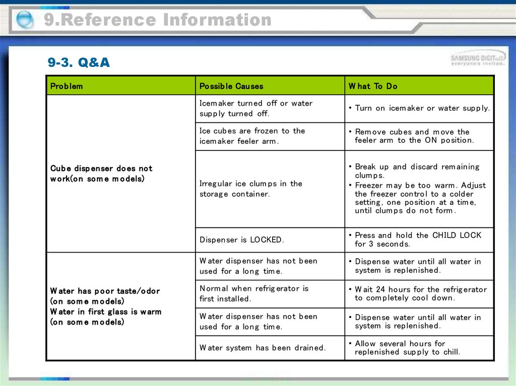
9.Reference Information9-3. Q&A
Pro b lem
Cub e disp enser do es no t
w o rk(o n so m e m o dels)
W ater has p o o r taste/o do r
(o n so m e m o dels)
W ater in first glass is w arm
(o n so m e m o dels)
Po ssib le Cau ses
W hat To D o
Icem aker turned off or water
sup p ly turned off.
• Turn on icem aker or water sup p ly.
Ice cub es are frozen to the
icem aker feeler arm .
• Rem ove cub es and m ove the
feeler arm to the ON position.
Irreg ular ice clum ps in the
storag e container.
• Break up and d iscard rem aining
clum ps.
• Freezer m ay b e too warm . Ad just
the freezer contro l to a cold er
setting , one position at a tim e,
until clum ps d o not form .
Dispenser is LOCKED.
• Press and ho ld the CHILD LOCK
for 3 second s.
W ater d ispenser has not b een
used for a long tim e.
• Dispense water until all water in
system is replenished .
N orm al when refrig erator is
first installed .
• W ait 24 hours for the refrig erator
to com p letely cool d own.
W ater d ispenser has not b een
used for a long tim e.
• Dispense water until all water in
system is replenished .
W ater system has b een d rained .
• Allo w several ho urs for
replenished sup p ly to chill.
131.
9.Reference Information9-3. Q&A
Pro b lem
W ater disp enser do es no t
w o rk(o n so m e m o dels)
W ater sp u rtin g fro m disp enser
(o n so m e m o dels)
W ater is no t disp ensed
(o n so m e m o dels) b u t
icem aker is w o rkin g
Po ssib le Cau ses
W hat To D o
W ater sup p ly line turned off or
not connected .
• See Installing the water line.
W ater filter clog g ed .
• Replace filter cartrid g e or rem ove
filter and install plug .
Air m ay b e trap p ed in the water
system .
• Press the d ispenser arm for at
least two m inutes.
Dispenser is LOCKED.
• Press and ho ld the CHILD LOCK
pad for 3 second s.
N ewly-installed filter cartrid g e.
• Run water from the d ispenser for
3 m inutes (ab out one and
a half gallons).
W ater in reservoir is frozen.
• Call for service.
Refrig erator control setting is
too cold .
• Set to a warm er setting .
Ice cub es stuck in icem aker.
(Green power lig ht on
icem aker b linking ).
• Turn off the icem aker, rem ove
cub es, and turn the icem aker
b ack on.
132.
9.Reference Information9-3. Q&A
Pro b lem
W ater o n kitchen flo o r o r
o n b o tto m of freezer
N o w ater o r ice cu b e
p ro du ctio n
Po ssib le Cau ses
W hat To D o
Drain in the b ottom of the
freezer clog g ed .
• See Care and cleaning .
• Check the filter lock
Cub es jam m ed in chute.
• Poke ice throug h with a wo od en
spoo n.
Sup p ly line or shutoff valve is
clog g ed .
• Call a plum b er.
W ater filter clog g ed .
• Replace filter cartrid g e or rem ove
filter and install plug .
Dispenser is LOCKED.
• Press and ho ld the CHILD LOCK
pad for 3 second s.