


 industry
Similar presentations:


Rubicon. System manual block mounter
1.
SYSTEM MANUALBLOCK MOUNTER
∅546 (4”_6”_8”)
RUBICON
2013.04.
2.
I N D E X* Notice for Safety*
1. Machine Specification
2. Operation Board (Touch Panel)
3. Preparation for Operation
4. Manual Operation
5. Automatic Operation
6. Maintenance
7. PLC Program
8. PLC I/O
9. Electric Circuit Drawing
10. Entire Assembly Drawing
11. Partial Assembly Drawing(Part List)
12. Pneumatic Circuit Drawing
Regarding the any case of accident and incidents occurred by customer’s
program modification or parts change in this equipment, maker has no
responsibility on this and will take counter-actions having discussion with
customer. Please contact maker before do the modification and change works
by customer.
3.
* Notice for Safety*4.
General Safety InstructionsThis manual is including information related to secure the safety. Please be
fully aware of this manual before using the system.
1) Make sure people are stay out of working area of the machine before input
power of system.
2) When the system is ceased for temporary blackout, the system is returning
to the initial state. After restoring the power, system requires following the
operation procedure.
3) Remove obstacles when system is operated as checking if water, dust and
others are remained on the system. Regular checking of system is required as
well.
4) System requires protection from impact and prohibits from using water and
chemicals which need soft sponge and brush for cleaning.
5) When manual operating is required, please check whether intervention is
found in each part or not and then perform the system.
6) System has to be powered off when repair work, inspection of other parts,
system check-up, and JIG exchange are required.
7) Operating parts has to be regularly maintained with injection of oil and
grease.
8) Do not treat machine with wet glove and put your hand on the machine during
the automatic operation
9) Secure enough space when the machine is arranged after lay-out.
10) Prohibit other people to treat machine than technicians.
11) Do not operate machine rashly as the internal panel of system is considte
of sensitive electronic parts.
12) Block the power completely when the machine is on setting.
13) Do not touch electricity panel and transmission without caution for
prevention of electrocute during the raining season.
14) Do not put or touch your hand on each transmitted cylinder and slider.
15) Block the air first when each cylinder requires setting.
16) Check cooling water periodically to repair the water leak all the time.
17) Please contact Dineeng for any system inquires
5.
1. Machine Specification6.
1. Device Composition and Specification1. Device Overview
This device allows the set amount of wafer to attach to the washed and
heated ceramic
2. Specification
- The wafers that correspond to the device must be designed and produced
within the combination range of 4” (Dia 100mm) , 6” (Dia 150mm) ,
and 8” (Dia 200mm).
- The ceramic blocks that correspond to the device are as shown below.
Ceramic Block : Dia 546 * 15t
3. Device portions Specification
3.1 Frame
Frame must be used with AL PROFILE, and the COVER must be used with the
transparent uninterruptible acryl.
Machine’s total SIZE 2300 * 2760 * 1970H
3.2 Pre-heating and Heating
Pre-heating and heating portion’s block SIZE must correspond to the ceramic
block Dia 546.
3.3 PUSH
The cylinder is pushed for the loading of wafer.
Design so that the structure is modifiable in to 4”, 6”, 8”.
3.4 ELEVATOR
AC Motor and Ball screw are operated up-and-down in accordance with the 2
cassette/ 50 wafer standard.
7.
3.5 WAFER FEEDFor transportation use the cylinder, and the transport plate jig must be designed
so that it is compatible to a combination of types
3.6 SPIN
Rotational activity is run through AC Servo Motor 3rd stage, and each setting
must be changeable.
The spinning shaft is treated with aluminum hard anodizing.
3.7 ROTATING
The rotation of wafer is carried out with the rotating cylinder, and vacuum
adsorption
The wafer attaching location is to be adjustable to the ceramic block’s size.
3.8 INDEX and MOUNTING
The block SIZE must correspond with the ceramic block Dia 546.
Decide the number of segmentation according to the ceramic block size.
The heater should be set so that its maximum heating temperature is 150
degrees (Celsius)
3.9 STAMP
Stamping is done with the air cylinder, and the wafer attachment location should
be adjustable.
Stamping must be done with special rubber pad(silicon) to realize pressure from
the middle.
3.10 BAKING
Heating(non-contact) the wafer at any time.
Maximum temperature is 200 degrees(Celsius)
The size of heater is produced with 8’’ standard.
8.
3.11 WAX DISPENSERForward-backward transport is executed through step motor, up-down
transport is run through air cylinder.
The wax discharge uses the normal amount of discharge valve and compressor
tank.
3.12 COOLING
Cool water is circulated in the aluminum block to cool the ceramic block.
The block SIZE must correspond with the ceramic block Dia 546.
The product’s damage is minimized by attaching the silicon pad on the cool
press.
3.13 BLOCK FEED
Use the Motor for the transportation of the ceramic block, and transport two
ceramic blocks simultaneously with 2 arms.
The opening, closing of the arm is done with the air cylinder.
3.14 Block Loading portion
One block can load up to 4 cassettes, and manually loaded on the device if
there is discrepancy. The loading portion is run with the static motor and
transported up and down through the pitch sensor. The block cassette’s sensor
detects ON/OFF, and the block transportation uses the motor.
3.15 Block Unloading portion
A block can be loaded with 4 per cassette, and unloaded manually when there
is significant discrepancy. The unloading portion is run with the static motor and
transported up and down through the pitch sensor. The block cassette’s sensor
detects ON/OFF, and the block transportation uses the motor.
9.
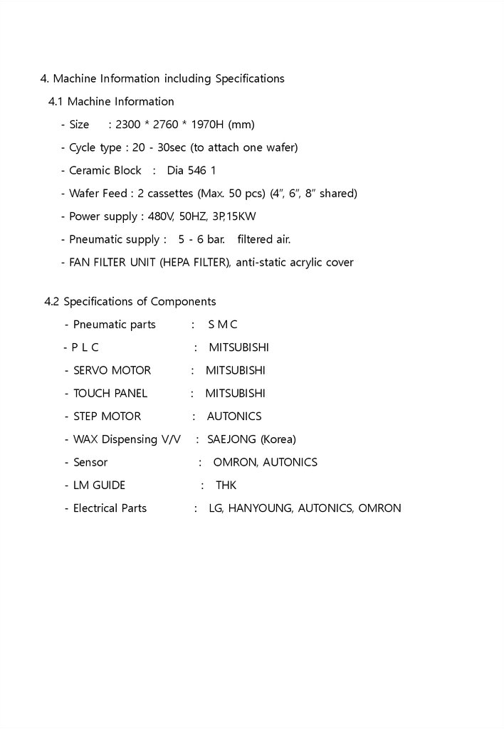
4. Machine Information including Specifications4.1 Machine Information
- Size
: 2300 * 2760 * 1970H (mm)
- Cycle type : 20 - 30sec (to attach one wafer)
- Ceramic Block
:
Dia 546 1
- Wafer Feed : 2 cassettes (Max. 50 pcs) (4”, 6”, 8” shared)
- Power supply : 480V, 50HZ, 3P,15KW
- Pneumatic supply :
5 - 6 bar.
filtered air.
- FAN FILTER UNIT (HEPA FILTER), anti-static acrylic cover
4.2 Specifications of Components
- Pneumatic parts
:
-PLC
:
MITSUBISHI
- SERVO MOTOR
:
MITSUBISHI
- TOUCH PANEL
:
MITSUBISHI
- STEP MOTOR
:
AUTONICS
- WAX Dispensing V/V
: SAEJONG (Korea)
- Sensor
:
OMRON, AUTONICS
- LM GUIDE
:
THK
- Electrical Parts
:
LG, HANYOUNG, AUTONICS, OMRON
10.
2. OPREATION BOARD11.
2. OPERATION BOARD2-1 OPERATION BOARD
- POWER : Turning the device power On or Off .
- MANUAL/AUTO : Sets for Manual or Auto operation.
- AUTO START : Initiates automatic run.
- HOME/RESET : Moves to the initial point for manual operation.
- UNLOADING CASSETTE : Replace the cassette and press down once unloading
cassette work is finished.
- LOADING CASSETTE : Replace the cassette and press down once unloading
cassette work is finished.
- BAKE HEATER TEMP : Set the temperature of baking heater.
- PRE.HEATER TEMP : Set the temperature of preheat block.
- INDEX HEATER TEMP : Set the temperature of heating block.
- MAIN AIR : Check the value of MAIN AIR.
- Touch Panel Screen : Set or display the state of machine.
12.
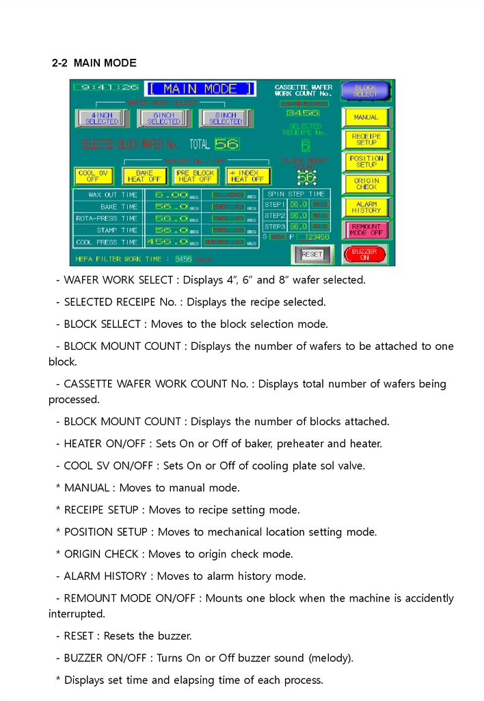
2-2 MAIN MODE- WAFER WORK SELECT : Displays 4”, 6” and 8” wafer selected.
- SELECTED RECEIPE No. : Displays the recipe selected.
- BLOCK SELLECT : Moves to the block selection mode.
- BLOCK MOUNT COUNT : Displays the number of wafers to be attached to one
block.
- CASSETTE WAFER WORK COUNT No. : Displays total number of wafers being
processed.
- BLOCK MOUNT COUNT : Displays the number of blocks attached.
- HEATER ON/OFF : Sets On or Off of baker, preheater and heater.
- COOL SV ON/OFF : Sets On or Off of cooling plate sol valve.
* MANUAL : Moves to manual mode.
* RECEIPE SETUP : Moves to recipe setting mode.
* POSITION SETUP : Moves to mechanical location setting mode.
* ORIGIN CHECK : Moves to origin check mode.
- ALARM HISTORY : Moves to alarm history mode.
- REMOUNT MODE ON/OFF : Mounts one block when the machine is accidently
interrupted.
- RESET : Resets the buzzer.
- BUZZER ON/OFF : Turns On or Off buzzer sound (melody).
* Displays set time and elapsing time of each process.
13.
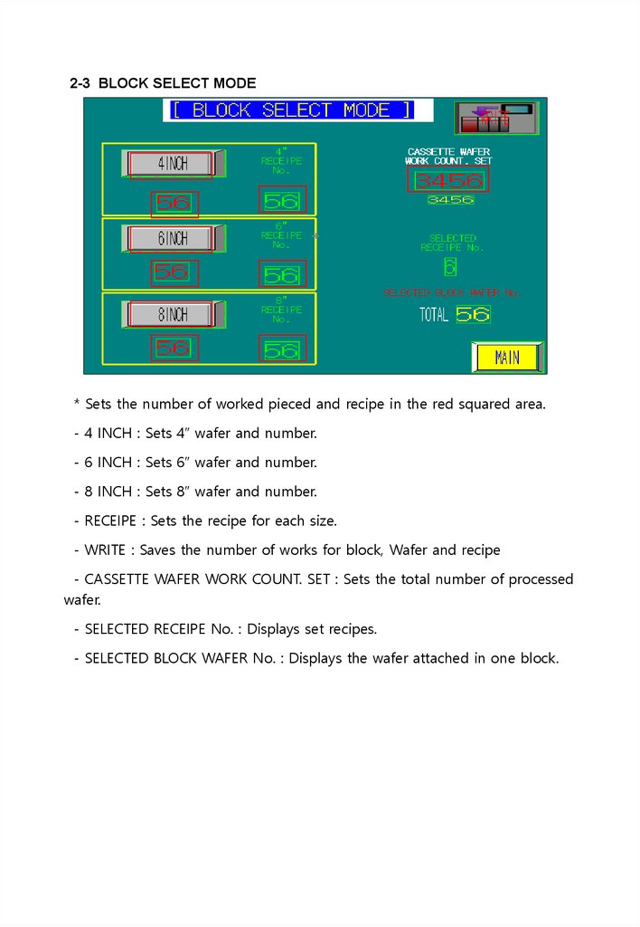
2-3 BLOCK SELECT MODE* Sets the number of worked pieced and recipe in the red squared area.
- 4 INCH : Sets 4” wafer and number.
- 6 INCH : Sets 6” wafer and number.
- 8 INCH : Sets 8” wafer and number.
- RECEIPE : Sets the recipe for each size.
- WRITE : Saves the number of works for block, Wafer and recipe
- CASSETTE WAFER WORK COUNT. SET : Sets the total number of processed
wafer.
- SELECTED RECEIPE No. : Displays set recipes.
- SELECTED BLOCK WAFER No. : Displays the wafer attached in one block.
14.
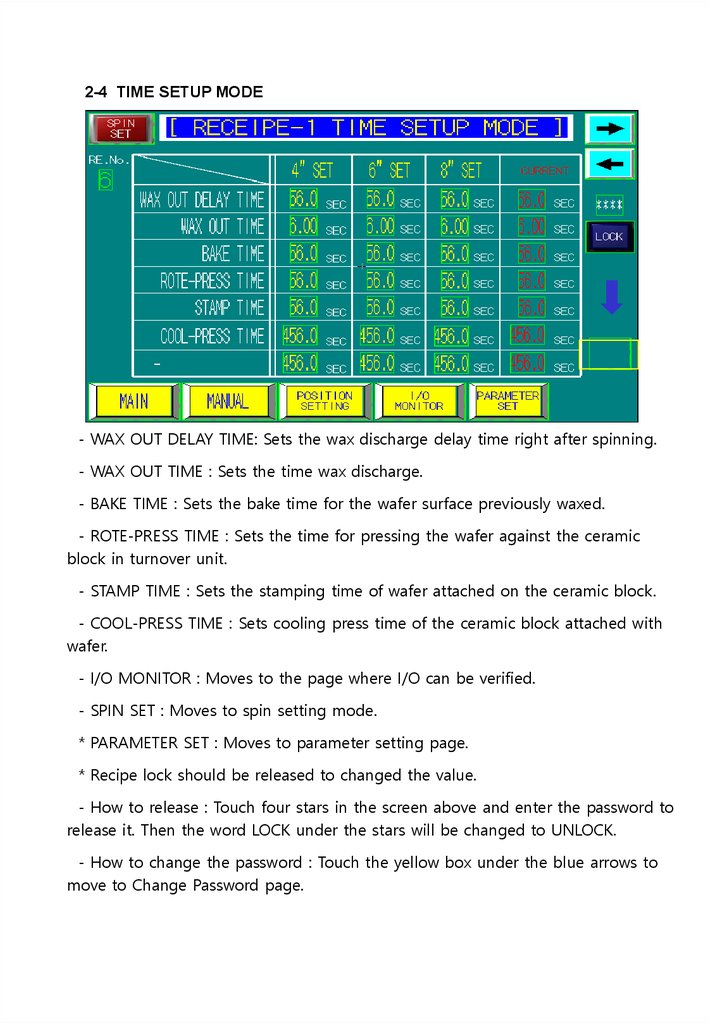
2-4 TIME SETUP MODE- WAX OUT DELAY TIME: Sets the wax discharge delay time right after spinning.
- WAX OUT TIME : Sets the time wax discharge.
- BAKE TIME : Sets the bake time for the wafer surface previously waxed.
- ROTE-PRESS TIME : Sets the time for pressing the wafer against the ceramic
block in turnover unit.
- STAMP TIME : Sets the stamping time of wafer attached on the ceramic block.
- COOL-PRESS TIME : Sets cooling press time of the ceramic block attached with
wafer.
- I/O MONITOR : Moves to the page where I/O can be verified.
- SPIN SET : Moves to spin setting mode.
* PARAMETER SET : Moves to parameter setting page.
* Recipe lock should be released to changed the value.
- How to release : Touch four stars in the screen above and enter the password to
release it. Then the word LOCK under the stars will be changed to UNLOCK.
- How to change the password : Touch the yellow box under the blue arrows to
move to Change Password page.
15.
2-5 PARAMETER SET MODE- HEFA FILTER CHANGE TIME SET : Replace the Hepa-filter once alarm occurs
after the set period.
- LOADING E/V C/V 1,2 STOP TIME : Roller stops at the preset time.
- UNLOADING E/V C/V 1,2 STOP TIME : Roller stops at the preset time.
- COOL PRESS USE_SELECT : Set if the cooling press is used or not after moving
wafer-attached ceramic block to cooling stage in auto mode.
16.
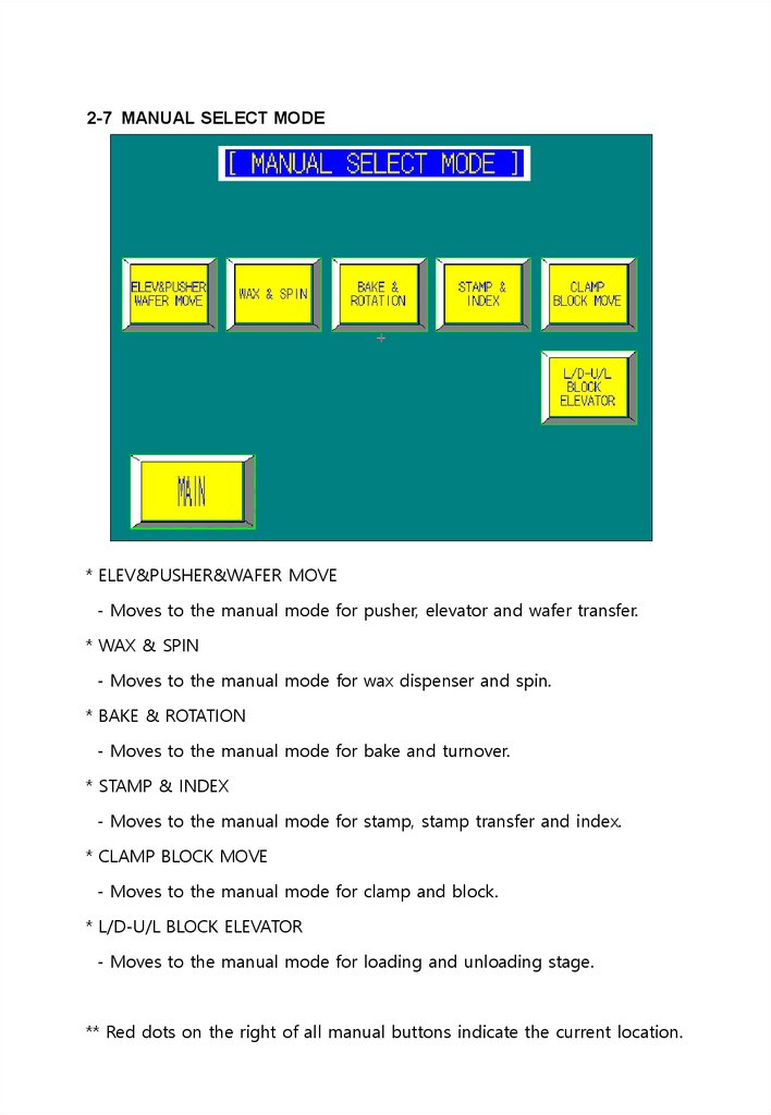
2-7 MANUAL SELECT MODE* ELEV&PUSHER&WAFER MOVE
- Moves to the manual mode for pusher, elevator and wafer transfer.
* WAX & SPIN
- Moves to the manual mode for wax dispenser and spin.
* BAKE & ROTATION
- Moves to the manual mode for bake and turnover.
* STAMP & INDEX
- Moves to the manual mode for stamp, stamp transfer and index.
* CLAMP BLOCK MOVE
- Moves to the manual mode for clamp and block.
* L/D-U/L BLOCK ELEVATOR
- Moves to the manual mode for loading and unloading stage.
** Red dots on the right of all manual buttons indicate the current location.
17.
2-8 ELEV & PUSHER MANUAL* PUSHER ASSY : Pushed the stacked wafer in the cassette.
- FORWARD : Moves pusher forward.
- BACKWARD : Moves pusher backward.
* LD ELEV : Stacks cassettes in two stories and move them up or down at a pitch.
- UP/(ORG) : Moves to initial location by lifting the elevator.
- 1SLOT POS DOWN : Moves to the first position.
- 26SLOT POS DOWN : It is used at 25th position and moves to 26th position.
- PITCH UP : Lifts 1 pitch.
- PITCH DOWN : Lowers 1 pitch.
- STOP : Stops the elevator regardless of the pitch.
-> SLOT POS: Displays the location of current cassette slot.
-> CURRENT POS : Displays the location of current cassett.
* WAFER MOVE : Pushed wafer can be moved to spinning or turnover unit.
- FORWARD : Moves Wafer transfer forward.
- BACKWARD : Moves Wafer transfer backward.
18.
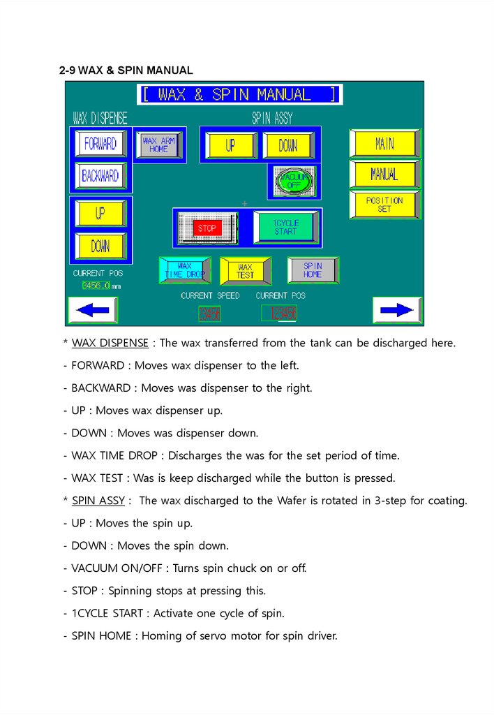
2-9 WAX & SPIN MANUAL* WAX DISPENSE : The wax transferred from the tank can be discharged here.
- FORWARD : Moves wax dispenser to the left.
- BACKWARD : Moves was dispenser to the right.
- UP : Moves wax dispenser up.
- DOWN : Moves was dispenser down.
- WAX TIME DROP : Discharges the was for the set period of time.
- WAX TEST : Was is keep discharged while the button is pressed.
* SPIN ASSY : The wax discharged to the Wafer is rotated in 3-step for coating.
- UP : Moves the spin up.
- DOWN : Moves the spin down.
- VACUUM ON/OFF : Turns spin chuck on or off.
- STOP : Spinning stops at pressing this.
- 1CYCLE START : Activate one cycle of spin.
- SPIN HOME : Homing of servo motor for spin driver.
19.
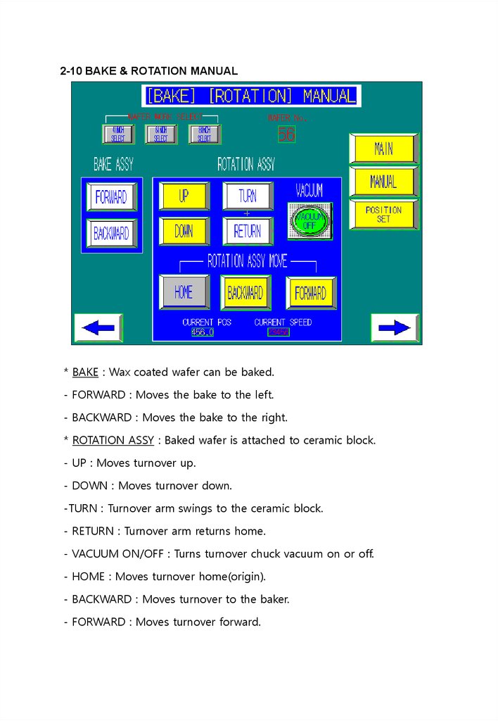
2-10 BAKE & ROTATION MANUAL* BAKE : Wax coated wafer can be baked.
- FORWARD : Moves the bake to the left.
- BACKWARD : Moves the bake to the right.
* ROTATION ASSY : Baked wafer is attached to ceramic block.
- UP : Moves turnover up.
- DOWN : Moves turnover down.
-TURN : Turnover arm swings to the ceramic block.
- RETURN : Turnover arm returns home.
- VACUUM ON/OFF : Turns turnover chuck vacuum on or off.
- HOME : Moves turnover home(origin).
- BACKWARD : Moves turnover to the baker.
- FORWARD : Moves turnover forward.
20.
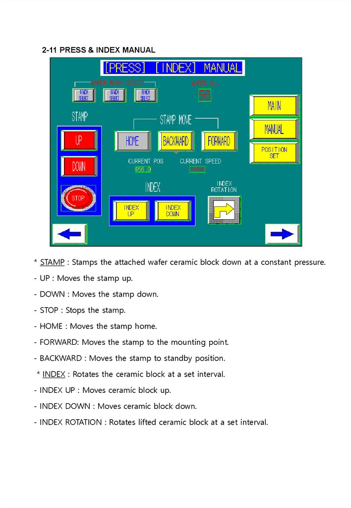
2-11 PRESS & INDEX MANUAL* STAMP : Stamps the attached wafer ceramic block down at a constant pressure.
- UP : Moves the stamp up.
- DOWN : Moves the stamp down.
- STOP : Stops the stamp.
- HOME : Moves the stamp home.
- FORWARD: Moves the stamp to the mounting point.
- BACKWARD : Moves the stamp to standby position.
* INDEX : Rotates the ceramic block at a set interval.
- INDEX UP : Moves ceramic block up.
- INDEX DOWN : Moves ceramic block down.
- INDEX ROTATION : Rotates lifted ceramic block at a set interval.
21.
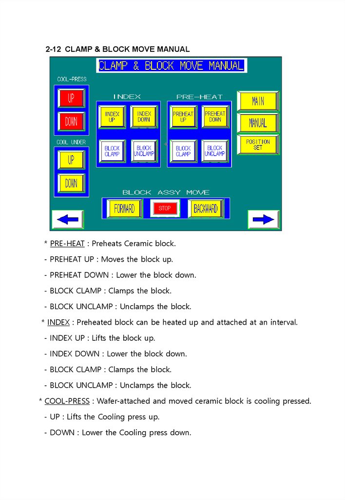
2-12 CLAMP & BLOCK MOVE MANUAL* PRE-HEAT : Preheats Ceramic block.
- PREHEAT UP : Moves the block up.
- PREHEAT DOWN : Lower the block down.
- BLOCK CLAMP : Clamps the block.
- BLOCK UNCLAMP : Unclamps the block.
* INDEX : Preheated block can be heated up and attached at an interval.
- INDEX UP : Lifts the block up.
- INDEX DOWN : Lower the block down.
- BLOCK CLAMP : Clamps the block.
- BLOCK UNCLAMP : Unclamps the block.
* COOL-PRESS : Wafer-attached and moved ceramic block is cooling pressed.
- UP : Lifts the Cooling press up.
- DOWN : Lower the Cooling press down.
22.
* COOL UNDER: The ceramic block with wafer attached and moved is cooleddown by means of water cooling system.
- UP : Lifts the block up.
- DOWN : Lowers the block down.
* BLCOK ASSY MOVE : Moves preheated block to the heater and mounted block
to the cooler.
- FORWARD : Moves block transfer to the left.
- BACKWARD : Moves block transfer to the right.
23.
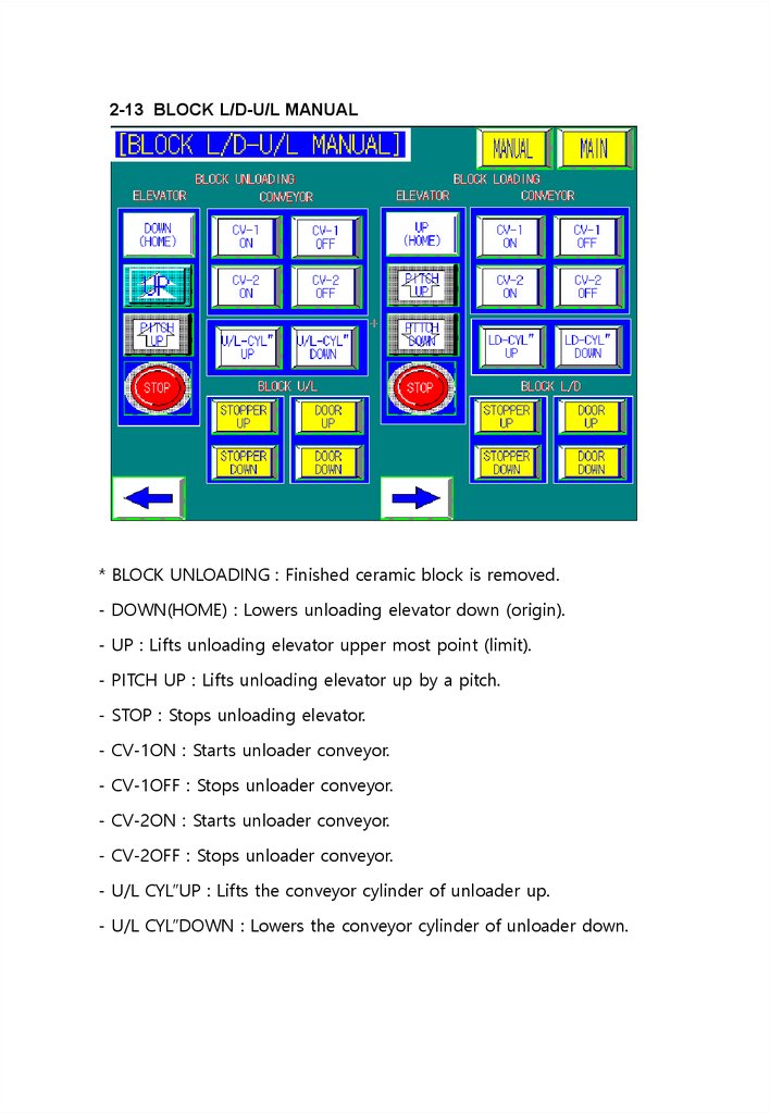
2-13 BLOCK L/D-U/L MANUAL* BLOCK UNLOADING : Finished ceramic block is removed.
- DOWN(HOME) : Lowers unloading elevator down (origin).
- UP : Lifts unloading elevator upper most point (limit).
- PITCH UP : Lifts unloading elevator up by a pitch.
- STOP : Stops unloading elevator.
- CV-1ON : Starts unloader conveyor.
- CV-1OFF : Stops unloader conveyor.
- CV-2ON : Starts unloader conveyor.
- CV-2OFF : Stops unloader conveyor.
- U/L CYL”UP : Lifts the conveyor cylinder of unloader up.
- U/L CYL”DOWN : Lowers the conveyor cylinder of unloader down.
24.
* BLOCK LODING : The new ceramic block is inserted here.- UP(HOME) : Lifts loading elevator up (home).
- PITCH UP : Lifts loading elevator up by a pitch.
- PITCH DOWN : Lowers loading elevator by a pitch.
- STOP : Stops loading elevator from the running.
- CV-1ON : Starts loader conveyor.
- CV-1OFF : Stops loader conveyor.
- CV-2ON : Starts loader conveyor.
- CV-2OFF : Stops loader conveyor.
- L/D CYL”UP : Lifts loader conveyor cylinder up.
- L/D CYL”DOWN : Lowers loader conveyor cylinder down.
25.
2-14 ROTATE ARM POS SETTING MODE- HOME : Moves turnover home.
- FORWARD : Moves turnover forward position.
- BACKWARD : Moves turnover to set standby position.
* ROTATE ARM FORWARD POSITION SET
- 4” BLOCK : Sets 4” attachment position.
- 6” BLOCK : Sets 6” attachment position.
- 8” BLOCK : Sets 8” attachment position.
* ROTATE ARM BACKWARD POSITION SET
- ROTATE BACKWARD : Sets standby position(baking) of turnover arm
26.
2-15 STAMP PRESS POS SETTING MODE- PRESS HOME : Moves stamp home.
- STAMP POS : Moves stamp to the set position.
- BACK POS : Moves stamp to set standby position.
* STAMP PRESS FORWARD POS SET
- 4” BLOCK : Sets 4” attachment position.
- 6” BLOCK : Sets 6” attachment position.
- 8” BLOCK : Sets 8” attachment position.
* STAMP BACKWARD POS SET
- STAMP BACKWARD : Sets 4, 6 and 8” standby position.
27.
2-16 INDEX POS SETTING MODE- INDEX SPEED SET : Sets index speed.
-
: Rotates lifted Ceramic block by a preset interval.
- HOME : Starts homing of stepping driving motor for indexing.
- CURRENT POS : Displays the present location.
- CURRNET SPEED : Displays rotation velocity.
- ERROR CODE : Displays numbers (code) at motor error.
- JOG+ : Rotates it counterclockwise.
- JOG- : Rotates it clockwise.
* INDEX POSITION SET
(1ROTATION = 360° = 10,000PULSE)/wafer number per block.
2 EA : 5000 3 EA : 3333
8 EA : 1250
9 EA : 1111
4 EA : 2500
5 EA : 2000
10EA : 1000
14EA : 714
15EA : 667
16EA :625
20EA : 500
21EA : 476
22EA : 454
11 EA : 909
17EA : 588
23EA : 435
6 EA : 1667
12EA : 833
18EA : 555
24EA : 417
7EA :1429
13EA : 769
19EA : 526
28.
2-17 WAX ARM POS SETTING MODE- 4” FORWARD POS : Sets forward position and velocity for 4”.
- 4” BACKWARD POS : Sets backward position and velocity for 4”.
- 6” FORWARD POS : Sets forward position and velocity for 6”.
- 6” BACKWARD POS : Sets backward position and velocity for 6”.
- 8” FORWARD POS : Sets forward position and velocity for 8”.
- 8” BACKWARD POS : Sets backward position and velocity for 8”.
- WAX ARM WAIT POS : Sets waiting position of WAX ARM and the velocity.
* FORWARD : WAX ARM moves forward.
* BACKWARD : WAX ARM moves backward.
* WAX ARM HOME : Moves WAX ARM home.
* WAIT POSITION : Moves WAX ARM to Waiting position.
- CURRENT POS : Displays the present position.
- CURRENT SPEED : Displays moving velocity.
- ERROR CODE : Displays numbers (code) at motor error.
- JOG+ : Moves forward.
- JOG- : Moves backward.
- JOG LOW/HIGH : JOG motion velocity can be set for slower or faster.
29.
2-18 ELEV POS SETTING MODE- ELEV HOME : Moves elevator home.
- 1SLOT POS DOWN : Moves elevator to cassette #1 point.
- 26SLOT POS DOWN : Moves elevator to cassette #26 point.
- 1PITCH UP : Lifts elevator up by one cassette pitch.
- 1PITCH DOWN : Lowers elevator down by one cassette pitch.
* LD ELEV 1SLOT DOWN POSITION SET
- 4” 1SLOT POSITION : Specifies #1 cassette point for 4”.
- 6” 1SLOT POSITION : Specifies #1 cassette point for 6”.
- 8” 1SLOT POSITION : Specifies #1 cassette point for 8”.
* LD ELEV 26SLOT DOWN POSITION SET
- 4” 26SLOT POSITION : Specifies #26 cassette point for 4”.
- 6” 26SLOT POSITION : Specifies #26 cassette point for 6”.
- 8” 26SLOT POSITION : Specifies #26 cassette point for 8”.
* LD ELEV PITCH POSITION SET
- 4” PITCH POSITION : Specifies one pitch’s values for 4”.
- 6” PITCH POSITION : Specifies one pitch’s values for 6”.
- 8” PITCH POSITION : Specifies one pitch’s values for 8”.
30.
2-19 SPIN SET MODE- HOME : Performs homing of servo driver for spin.
- 1CYCLE START : Performs one cycle of spin.
- CURRENT SPEED : Displays the velocity of spinning.
- CURRENT POS : Displays the present location.
* The value for step 4’s stop position should be greater than that of step 3th end position.
It stops at the origin if red underlined value is even number. It stops at 180 degreed point if
the value is odd number.
- VACUUM ON/OFF : Turns spin chuck’s vacuum on or off.
- UP : Lifts spin up.
- DOWN : Lowers spin down.
- TIME SETUP : Moves to time setting mode.
- RECEIPE : Displays the recipe currently applied.
31.
2-20 ALARM HISTORY MODE- Displays the history of alarm (Date and Time)
- Can delete all or selected history
32.
2-21 RECEIPE & POS PASSWORD- Touch number box of screen allows to change the password.
33.
2-22 POSITION MODE PASSWARD INPUT- Entering position setting mode requires password
- Touch four yellow stars of screen allow to enter password
- Same password is used for recipe
- Once change the password, it will be applied for recipe menu as well
34.
2-23 INPUT MONITORDisplays INPUT
content and ON/OFF Condition
35.
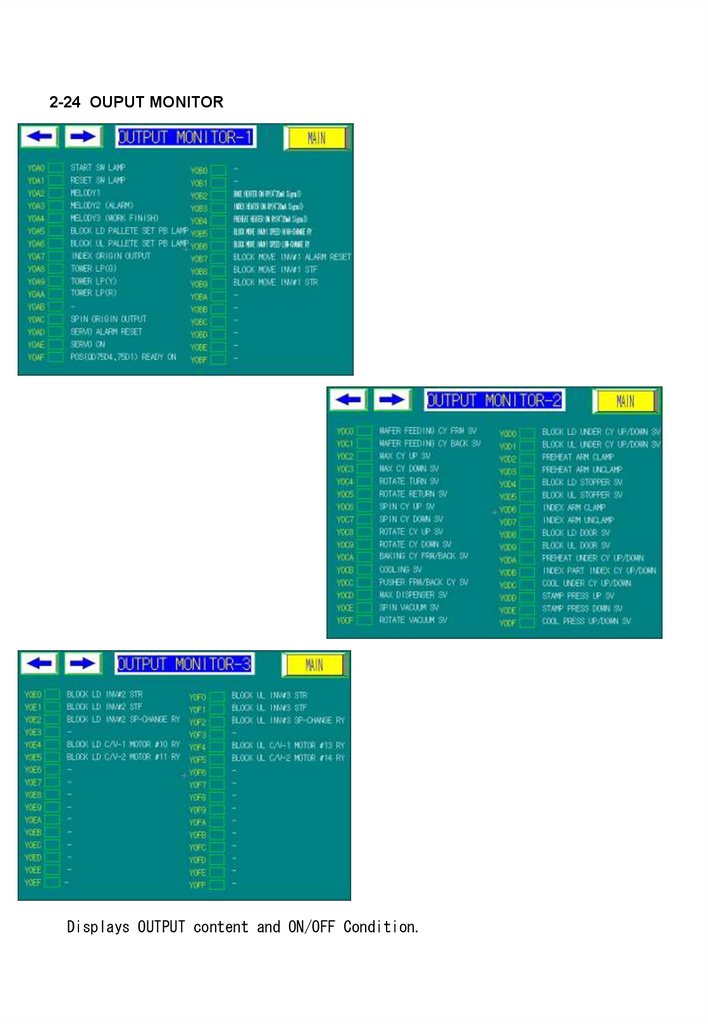
2-24 OUPUT MONITORDisplays OUTPUT content and ON/OFF Condition.
36.
2-25 ALARM* Mark the respective alarm contents on the main mode.
- BZ ON/OFF : Set the Boozer (melody) ON/OFF.
- RESET : RESET the alarm.
* EMERGENCY STOP
- Situation where the emergency button has been pressed, and can be
cancelled by turning the button to the right
- Remove the dangerous factors at manual mode and RESET.
* SPIN SERVO CONTROLLER ERROR
- When there is an error on the motor of the spinning portion, the alarm number
of the servo motor driver at the reverse side of the device must be checked
and consulted with the producer.
* BLOCK MOVE INVERTER ERROR
- The error from the inverter which drives the motor when the block is
transported left-right. The inverter alarm number is checked in the
manual(pamphlet).
* BAKE TEMP ALARM
- When the bake heater’s temperature is lower or higher than the set AL-H, ALL, press BZ OFF until the temperature reaches the goal temperature, and
check whether the temperature has gone up.
* PREHEAT TEMP ALARM
- When the pre-heater’s temperature is lower or higher than the set AL-H, ALL, press BZ OFF until the temperature reaches the goal temperature, and
check whether the temperature has gone up.
* STAMP INDEX TEMP ALARM
- When the index heater’s temperature is lower or higher than the set AL-H,
AL-L, press BZ OFF until the temperature reaches the goal temperature,
and check whether the temperature has gone up.
* INDEX(AXIS1) POS UNIT ERROR
- Check the stepping motor error that rotates the index, and the error code in
the setting mode, and then RESET before reporting to the producer and
receive action
* ROTATE ARM(AXIS2)POS UNIT ERROR
- Check the stepping motor error that drives the rotation’s forward-backward
location and the error code from the setting mode, and then RESET before
reporting to the producer and receive action
37.
* STAMP(AXIS3) POS UNIT ERROR- Check the stepping motor error that drives the stamp’s forward-backward
location and the error code from the setting mode, and then RESET before
reporting to the producer and receive action
* SPIN(AXIS4) POS UNIT ERROR
- For the spinning servo motor’s error in MANUAL mode, press HOME/RESET
for a long time to get the starting point to proceed.
* WAFER FULL WORK FINISH
- Transport the elevator to the starting point when using all 50 cassettes of the
Wafers.
After transporting and exchanging the wafer cassette, if the START button is
pressed for a long time it will automatically proceed.
* PUSHER FRW CY TIME OVER
- Alarm generated due to the excess of time elapsed during the forward
progress of the pusher cylinder. If there are any obstacles during the
forward progress remove them, check the air supply status and adjust the
speed using the speed cone. *
*PUSHER BACK CY TIME OVER
- Alarm generated due to the excess of time elapsed during the backward
progress of the pusher cylinder. If there are any obstacles during the
backward progress remove them, check the air supply status and adjust
the speed using the speed cone.
* WAX UP/DOWN CY UP TIME OVER
- Alarm generated due to the excess of time elapsed during the ascent of wax
dispenser cylinder. If there are any obstacles during the ascent, remove the
obstacle, check the air supply status, and adjust the speed using the
speed cone.
* WAX UP/DOWN CY DOWN TIME OVER
- Alarm generated due to the excess of time elapsed during the descent of wax
dispenser cylinder. If there are any obstacles during the descent, remove
the obstacle, check the air supply status, and adjust the speed using the
speed cone.
* SPIN VACUUM TIME OVER
- Alarm generated when the spin CY level of vacuum goes lower than the
certain level of vacuum on the wafer. If deemed that the wafer is still
useable press RETRY and during the process if the wafer gets damaged,
stop the process and reset it.
38.
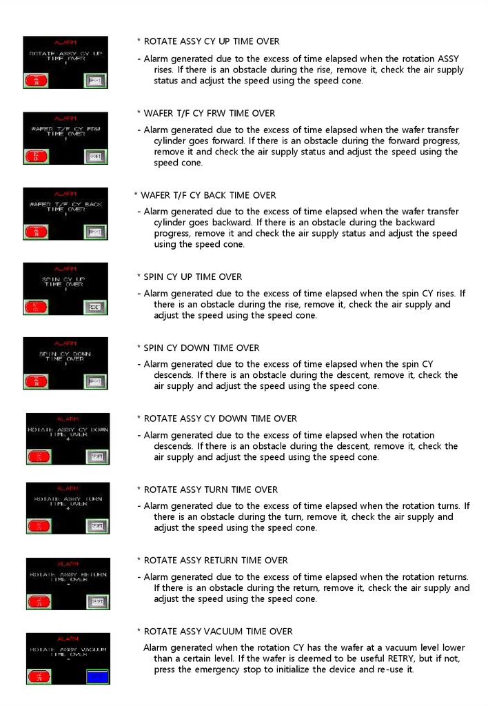
* ROTATE ASSY CY UP TIME OVER- Alarm generated due to the excess of time elapsed when the rotation ASSY
rises. If there is an obstacle during the rise, remove it, check the air supply
status and adjust the speed using the speed cone.
* WAFER T/F CY FRW TIME OVER
- Alarm generated due to the excess of time elapsed when the wafer transfer
cylinder goes forward. If there is an obstacle during the forward progress,
remove it and check the air supply status and adjust the speed using the
speed cone.
* WAFER T/F CY BACK TIME OVER
- Alarm generated due to the excess of time elapsed when the wafer transfer
cylinder goes backward. If there is an obstacle during the backward
progress, remove it and check the air supply status and adjust the speed
using the speed cone.
* SPIN CY UP TIME OVER
- Alarm generated due to the excess of time elapsed when the spin CY rises. If
there is an obstacle during the rise, remove it, check the air supply and
adjust the speed using the speed cone.
* SPIN CY DOWN TIME OVER
- Alarm generated due to the excess of time elapsed when the spin CY
descends. If there is an obstacle during the descent, remove it, check the
air supply and adjust the speed using the speed cone.
* ROTATE ASSY CY DOWN TIME OVER
- Alarm generated due to the excess of time elapsed when the rotation
descends. If there is an obstacle during the descent, remove it, check the
air supply and adjust the speed using the speed cone.
* ROTATE ASSY TURN TIME OVER
- Alarm generated due to the excess of time elapsed when the rotation turns. If
there is an obstacle during the turn, remove it, check the air supply and
adjust the speed using the speed cone.
* ROTATE ASSY RETURN TIME OVER
- Alarm generated due to the excess of time elapsed when the rotation returns.
If there is an obstacle during the return, remove it, check the air supply and
adjust the speed using the speed cone.
* ROTATE ASSY VACUUM TIME OVER
Alarm generated when the rotation CY has the wafer at a vacuum level lower
than a certain level. If the wafer is deemed to be useful RETRY, but if not,
press the emergency stop to initialize the device and re-use it.
39.
* STAMP PRESS DOWN TIME OVER- Alarm generated due to the excess of time elapsed when the stamp press
cylinder descends. If there is any obstacle during the descent, remove it,
check the air supply status, and adjust the speed using the speed cone..
* INDEX CY UP TIME OVER
- Alarm generated due to the excess of time elapsed when the index cylinder
rises. If there is any obstacle during the rise, remove it, check the air
supply status, and adjust the speed using the speed cone.
* INDEX CY DOWN TIME OVER
- Alarm generated due to the excess of time elapsed when the index cylinder
descends. If there is any obstacle during the descent, remove it, check the
air supply status and adjust the speed using the speed cone.
* PREHEAT UNDER CY UP TIME OVER
Alarm generated due to the excess of time elapsed when the single stage
cylinder under the pre-heater portion rises. If there is any obstacle during
the rise, remove it, check the air supply status and adjust the speed using
the speed cone.
* PREHEAT UNDER CY DOWN TIME OVER
Alarm generated due to the excess of time elapsed when the single stage
cylinder under the pre-heater portion descends. If there is any obstacle
during the descent, remove it, check the air supply status and adjust the
speed using the speed cone.
* PREHEAT CLAMP CLAMP TIME OVER
- Alarm generated due to the excess of time elapsed when the pre-heat clamp
cylinder clamped. If there is any obstacle during the clamp, remove it,
check the air supply status, and adjust the speed using the speed cone.
* PREHEAT CLAMP UNCLAMP TIME OVER
- Alarm generated due to the excess of time elapsed when the pre-heat clamp
cylinder unclamped. If there is any obstacle during the unclamp, remove it,
check the air supply status, and adjust the speed using the speed cone.
* STAMP INDEX CLAMP CLAMP TIME OVER
- Alarm generated due to the excess of time elapsed when the index clamp
cylinder clamped. If there is any obstacle during the clamp, remove it,
check the air supply status, and adjust the speed using the speed cone.
* STAMP INDEX CLAMP UNCLAMP TIME OVER
- Alarm generated due to the excess of time elapsed when the index clamp
cylinder unclamped. If there is any obstacle during the unclamp, remove it,
check the air supply status, and adjust the speed using the speed cone.
40.
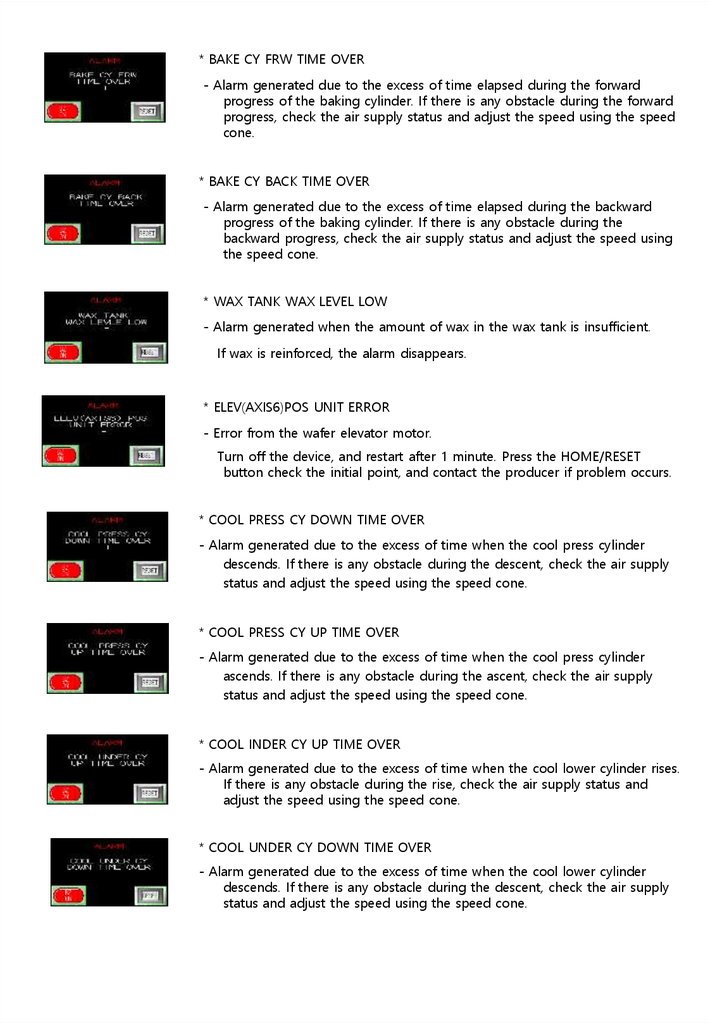
* BAKE CY FRW TIME OVER- Alarm generated due to the excess of time elapsed during the forward
progress of the baking cylinder. If there is any obstacle during the forward
progress, check the air supply status and adjust the speed using the speed
cone.
* BAKE CY BACK TIME OVER
- Alarm generated due to the excess of time elapsed during the backward
progress of the baking cylinder. If there is any obstacle during the
backward progress, check the air supply status and adjust the speed using
the speed cone.
* WAX TANK WAX LEVEL LOW
- Alarm generated when the amount of wax in the wax tank is insufficient.
If wax is reinforced, the alarm disappears.
* ELEV(AXIS6)POS UNIT ERROR
- Error from the wafer elevator motor.
Turn off the device, and restart after 1 minute. Press the HOME/RESET
button check the initial point, and contact the producer if problem occurs.
* COOL PRESS CY DOWN TIME OVER
- Alarm generated due to the excess of time when the cool press cylinder
descends. If there is any obstacle during the descent, check the air supply
status and adjust the speed using the speed cone.
* COOL PRESS CY UP TIME OVER
- Alarm generated due to the excess of time when the cool press cylinder
ascends. If there is any obstacle during the ascent, check the air supply
status and adjust the speed using the speed cone.
* COOL INDER CY UP TIME OVER
- Alarm generated due to the excess of time when the cool lower cylinder rises.
If there is any obstacle during the rise, check the air supply status and
adjust the speed using the speed cone.
* COOL UNDER CY DOWN TIME OVER
- Alarm generated due to the excess of time when the cool lower cylinder
descends. If there is any obstacle during the descent, check the air supply
status and adjust the speed using the speed cone.
41.
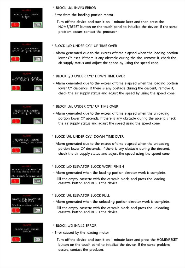
* BLOCK U/L INV#3 ERROR- Error from the loading portion motor.
Turn off the device and turn it on 1 minute later and then press the
HOME/RESET button on the touch panel to initialize the device. If the same
problem occurs contact the producer.
* BLOCK L/D UNDER CYL” UP TIME OVER
- Alarm generated due to the excess of time elapsed when the loading portion
lower CY rises. If there is any obstacle during the rise, remove it, check the
air supply status and adjust the speed by using the speed cone.
* BLOCK L/D UNDER CYL” DOWN TIME OVER
- Alarm generated due to the excess of time elapsed when the loading portion
lower CY descends. If there is any obstacle during the descent, remove it,
check the air supply status and adjust the speed by using the speed cone.
* BLOCK U/L UNDER CYL” UP TIME OVER
- Alarm generated due to the excess of time elapsed when the unloading
portion lower CY ascends. If there is any obstacle during the ascent, check
the air supply status and adjust the speed using the speed cone.
* BLOCK U/L UNDER CYL” DOWN TIME OVER
- Alarm generated due to the excess of time elapsed when the unloading
portion lower CY descends. If there is any obstacle during the descent,
check the air supply status and adjust the speed using the speed cone.
* BLOCK L/D ELEVATOR BLOCK WORK FINISH
- Alarm generated when the loading portion elevator work is complete.
Fill the empty cassette with the ceramic block, and press the loading
cassette button and RESET the device.
* BLOCK U/L ELEVATOR BLOCK FULL
- Alarm generated when the unloading portion elevator work is complete.
Fill the empty cassette with the ceramic block, and press the unloading
cassette button and RESET the device.
* BLOCK L/D INN#2 ERROR
- Error caused by the loading motor
Turn off the device and turn it on 1 minute later and press the HOME/RESET
button on the touch panel to initialize the device. If the same problem
occurs, contact the producer.
42.
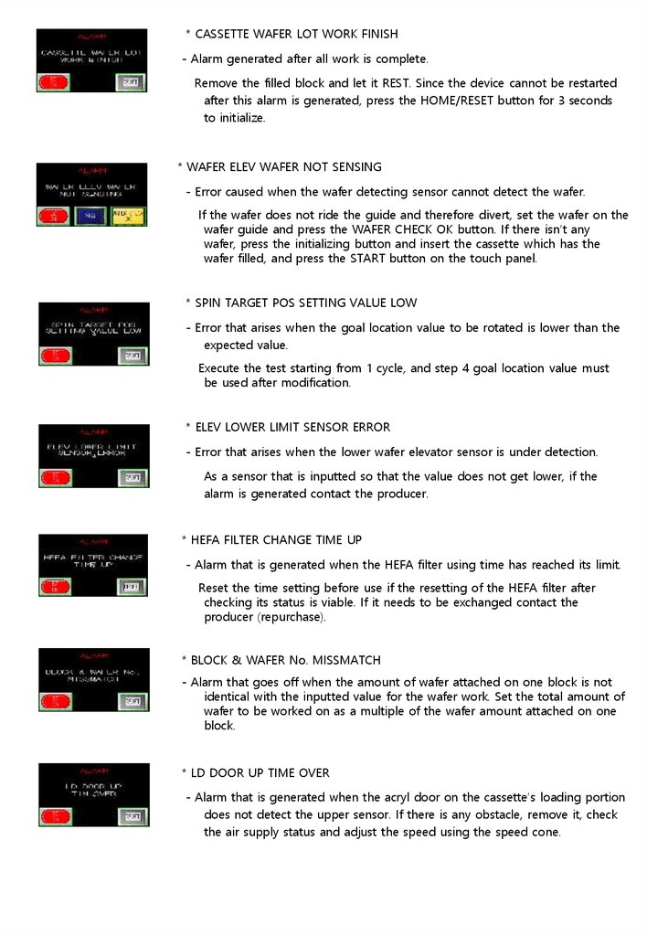
* CASSETTE WAFER LOT WORK FINISH- Alarm generated after all work is complete.
Remove the filled block and let it REST. Since the device cannot be restarted
after this alarm is generated, press the HOME/RESET button for 3 seconds
to initialize.
* WAFER ELEV WAFER NOT SENSING
- Error caused when the wafer detecting sensor cannot detect the wafer.
If the wafer does not ride the guide and therefore divert, set the wafer on the
wafer guide and press the WAFER CHECK OK button. If there isn’t any
wafer, press the initializing button and insert the cassette which has the
wafer filled, and press the START button on the touch panel.
* SPIN TARGET POS SETTING VALUE LOW
- Error that arises when the goal location value to be rotated is lower than the
expected value.
Execute the test starting from 1 cycle, and step 4 goal location value must
be used after modification.
* ELEV LOWER LIMIT SENSOR ERROR
- Error that arises when the lower wafer elevator sensor is under detection.
As a sensor that is inputted so that the value does not get lower, if the
alarm is generated contact the producer.
* HEFA FILTER CHANGE TIME UP
- Alarm that is generated when the HEFA filter using time has reached its limit.
Reset the time setting before use if the resetting of the HEFA filter after
checking its status is viable. If it needs to be exchanged contact the
producer (repurchase).
* BLOCK & WAFER No. MISSMATCH
- Alarm that goes off when the amount of wafer attached on one block is not
identical with the inputted value for the wafer work. Set the total amount of
wafer to be worked on as a multiple of the wafer amount attached on one
block.
* LD DOOR UP TIME OVER
- Alarm that is generated when the acryl door on the cassette’s loading portion
does not detect the upper sensor. If there is any obstacle, remove it, check
the air supply status and adjust the speed using the speed cone.
43.
* LD DOOR DOWN TIME OVERAlarm that is generated when the loading portion cassette of the acryl door
does not detect the lower sensor.
If there is any obstacle remove it, check the air supply status and adjust
the speed using the speed cone.
* LD STOPPER UP TIME OVER
- Alarm that sets off when the upper sensor of the stopper that fixes the
loading portion cassette is not detected. If there is an obstacle remove it,
check the air supply status and adjust the speed using the speed cone.
* LD STOPPER DOWN TIME OVER
- Alarm that sets off when the lower sensor of the stopper that fixes the
loading portion cassette is not detected. If there is an obstacle remove it,
check the air supply status and adjust the speed using the speed cone.
* UL DOOR UP TIME OVER
- Alarm that sets off when the upper sensor of the acryl door on the unloading
portion cassette is not detected. If there is an obstacle remove it, check
the air supply status and adjust the speed using the speed cone.
* UL DOOR DOWN TIME OVER
- Alarm that sets off when the lower sensor of the acryl door on the unloading
portion cassette is not detected. If there is an obstacle remove it, check
the air supply status and adjust the speed using the speed cone.
* UL STOPPER UP TIME OVER
- Alarm that sets off when the upper sensor of the stopper that fixes the
unloading portion cassette is not detected. If there is an obstacle remove it,
check the air supply status and adjust the speed with the speed cone.
* UL STOPPER DOWN TIME OVER
- Alarm that sets off when the lower sensor of the stopper that fixes the
unloading cassette is not detected. If there is an obstacle remove it, check
the air supply status and adjust the speed using the speed cone.
44.
*** If there is a TIME OVER alarm set off, check the air supply status, and use the respective cylinderspeed cone to adjust the transfer speed. Also, check if the respective cylinder sensor of the cylinder is
lit in red in a normal fashion, and exchange it if there is any problem.
*** If there is motor error check the error code and RESET the device. If repetitive error is occurred,
turn off the device let it rest for about 3 minutes before turning it back on to see whether it still has
the error. If the error continues consult with the producer.
45.
3. Preparation of Operation46.
3. Preparation of OperationA. POWER ON
*** Please follow below sequence for Power On Operation
① Set 1st power breaker on (Factory Power)
② Set NFB ON at the system control panel
③ Set each Circuit Protectors & NFB on of SYSTEM CONTROLLE
④ Set Power Switch on of OPERATION PANEL
⑤ Confirm PLC/NC status by RUN LED color (RED)
3-2. POWER OFF
*** Please follow below sequence for Power Off Operation
① In automatic operation mode, set the OPERATION STOP switch on
after system halt.
② Shut off the power of control panel and other parts.
3-3. Preparation for system operation (Ready status for operation)
① Check powered system control panel
② Check alarm of main control panel and make proper countermeasure
if any
③ Pneumatic system, PLC should be in the normal status and no
emergency stop signal is input
47.
4. Manual Operation48.
4. Manual Operation 4-1.Condition of Manual Operation◆ Switch to operation preparation status following sequence
◆ Switch OPERATION PANEL MANUAL/AUTO S/W to MANUAL
◆ Each mechanism can be operated by touch panel as described on chapter 2.
Notice) Each Software is programmed as Flip-Flop Sequence
49.
5. Automatic Operation50.
5. Automatic Operation5-1. Condition
◆ Automatic Operation is available only when whole machine is at the original location.
Be sure to check if cassettes and wafers are properly loaded
5-2. Automatic Operation
◆ Initiate automatic operation in sequence when necessary condition is satisfied.
5-2-1. Automatic Operation Start
- AUTO START = Mount wafers on ceramic block with liquid wax
Be sure to stay out of work space during operation
5-3. Stop and Closing of Automatic Operation
◆ Press RESET button longer than one second after operation cycle completed.
5-4. Emergency Stop Operation
- OP Stop, Emergency Stop = System Stop
◆ For emergency stop, press Emergency S/W to halt the system
◆ Release : Press RESET or switch to manual mode to release from emergency stop mode
51.
6. MAINTENANCE52.
6. MAINTENANCE6-1. Ji g Exchange met hod
1) PUSHER
-
- Move PUSHER to oriianl postition
-
-
2) SPIN CHUCK COVER
- SPIN PART Exchange for 2”
4” operation (Remove for 8”)
3) STAMP
- STAMP EXchange
4) PUSER HEIGHT JIG
- PUSHER HEIGHT
EXchange
53.
6-2. WAX TANK, DISPENSING VALVE* WAX TANK
- M O DEL : JB03-LRG
- Recomm ended A ir P ressure : 2~3 g f/cm 2
- Re leasing of a la rm and Buzzer :
Reset & Wax recharge
* DISPENSING VALVE
- M O DEL : SV 501
- M ax F lu id P ressure : 7 kg f/cm
2
- M ax a ir p ressure : 7 kg f/cm 2
- E ffective Tem p. Range : 5℃ ~ 43℃
- N EEDLE NOZZLE : 17
54.
6-3. Regulator1 ) STAM P
- U sage P ressure
4 IN CH : 0.03 M pa
6 IN CH : 0.04 M pa
8 IN CH : 0.03 ~ 0.04 M pa
2 ) ROTA ION CU S ION
- U sage P ressure
4 , 6 , 8 IN CH : 0.03 M Pa
55.
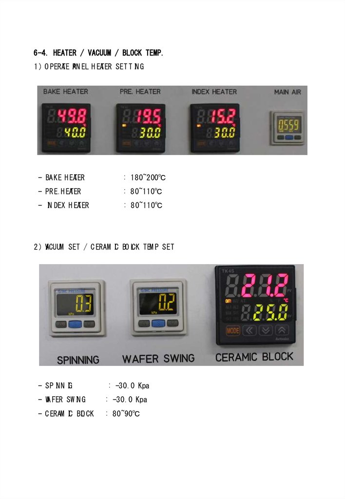
6-4. HEATER / VACUUM / BLOCK TEMP.1 ) O PERATE PAN EL H EATER SET T IN G
- BAKE H EATER
: 180~200℃
- PRE.H EATER
: 80~110℃
- IN DEX H EATER
: 80~110℃
2 ) VACUUM SET / C ERAM IC BO LCK TEM P. SET
- SP INN IG
: -30.0 Kpa
- WA FER SW IN G
: -30.0 Kpa
- C ERAM IC BLO CK
: 80~90℃
56.
6-5. BAKE HEATER / STAMP gap setting1 ) BAKE H EATER SET T ING
- Secure about 1~2mm gap be tween the bake heate r and wa fe r
2 ) STAM P SET T IN G
Secure about 3mm gap be tween the ce ram ic b lo ck and stam p
(use the 3 t silicon PA D)
57.
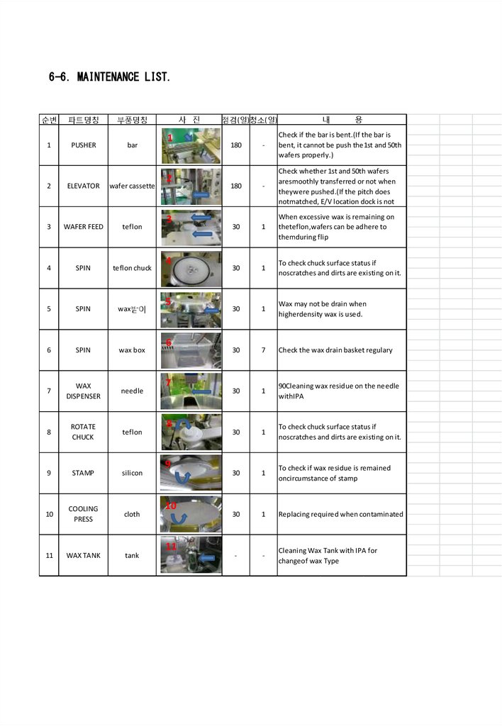
6-6. MAINTENANCE LIST.순번
파트명칭
부품명칭
1
PUSHER
bar
2
ELEVATOR
wafer cassette
3
WAFER FEED
teflon
4
SPIN
teflon chuck
5
SPIN
wax 받이
6
SPIN
wax box
7
WAX
DISPENSER
needle
8
ROTATE
CHUCK
teflon
9
STAMP
silicon
10
COOLING
PRESS
cloth
11
WAX TANK
tank
사 진
1
2
3
4
5
6
7
8
9
10
11
점검(일)청소( 일)
내
용
-
Check if the bar is bent.(If the bar is
bent, it cannot be push the1st and 50th
wafers properly.)
180
-
Check whether 1st and 50th wafers
aresmoothly transferred or not when
theywere pushed.(If the pitch does
notmatched, E/V location dock is not
30
1
When excessive wax is remaining on
theteflon,wafers can be adhere to
themduring flip
30
1
To check chuck surface status if
noscratches and dirts are existing on it.
30
1
Wax may not be drain when
higherdensity wax is used.
30
7
Check the wax drain basket regulary
30
1
90Cleaning wax residue on the needle
withIPA
30
1
To check chuck surface status if
noscratches and dirts are existing on it.
30
1
To check if wax residue is remained
oncircumstance of stamp
30
1
Replacing required when contaminated
-
-
Cleaning Wax Tank with IPA for
changeof wax Type
180
58.
7. PLC PROGRAM59.
8. PLC I/O60.
9. Electric Circuit Drawing61.
10. Overall Assembly Drawing62.
11. Partial Assembly Drawing(Including Parts List)