


")
 Cartridges and heaters")


")


")


 industry
Similar presentations:


")


Air Treatment system
1.
Air Treatment systemKnorr-Bremse Group
2.
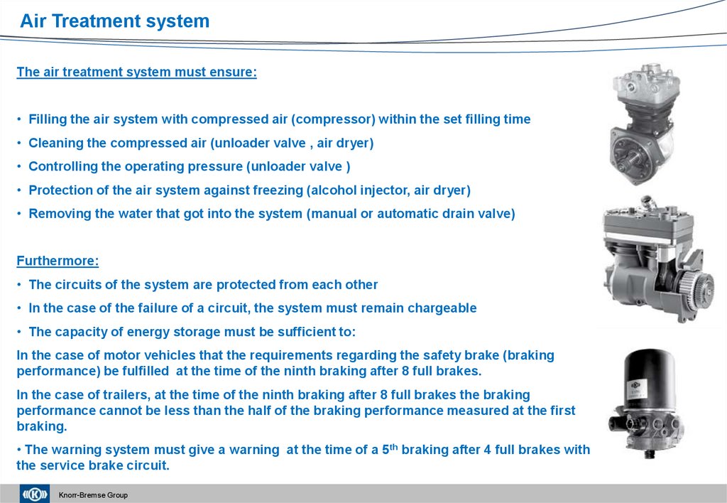
Air Treatment systemThe air treatment system must ensure:
• Filling the air system with compressed air (compressor) within the set filling time
• Cleaning the compressed air (unloader valve , air dryer)
• Controlling the operating pressure (unloader valve )
• Protection of the air system against freezing (alcohol injector, air dryer)
• Removing the water that got into the system (manual or automatic drain valve)
Furthermore:
• The circuits of the system are protected from each other
• In the case of the failure of a circuit, the system must remain chargeable
• The capacity of energy storage must be sufficient to:
In the case of motor vehicles that the requirements regarding the safety brake (braking
performance) be fulfilled at the time of the ninth braking after 8 full brakes.
In the case of trailers, at the time of the ninth braking after 8 full brakes the braking
performance cannot be less than the half of the braking performance measured at the first
braking.
• The warning system must give a warning at the time of a 5th braking after 4 full brakes with
the service brake circuit.
Knorr-Bremse Group
3.
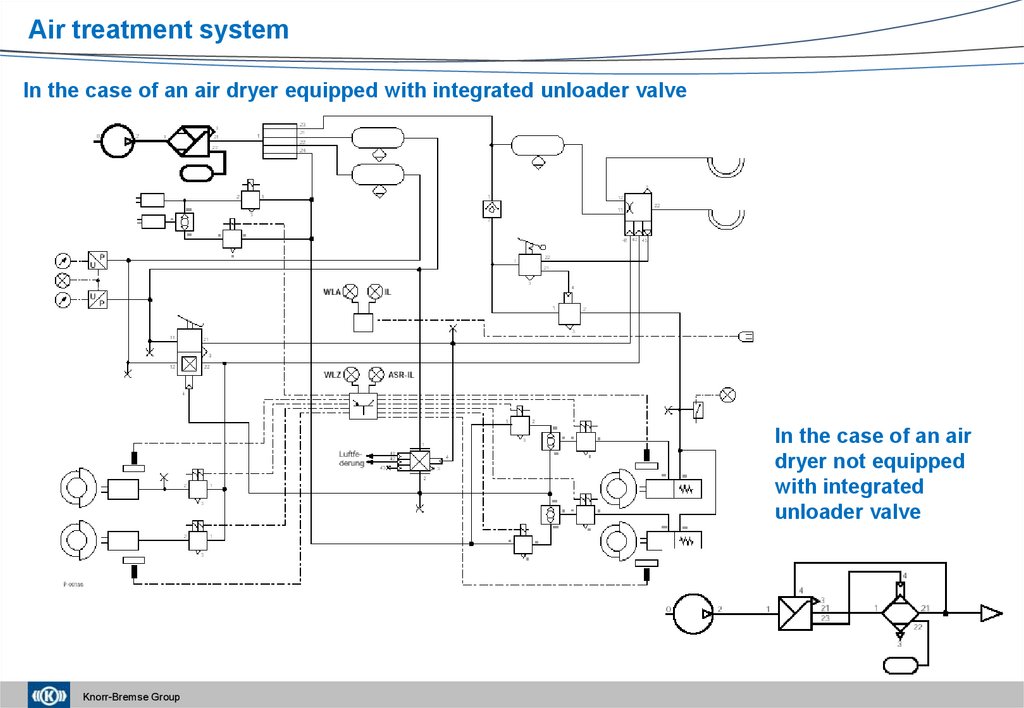
Air treatment systemIn the case of an air dryer equipped with integrated unloader valve
In the case of an air
dryer not equipped
with integrated
unloader valve
Knorr-Bremse Group
4.
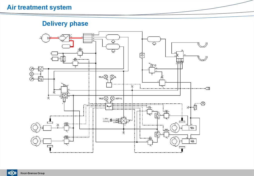
Air treatment systemDelivery phase
Knorr-Bremse Group
5.
Air treatment systemEnd of regeneration phase
Knorr-Bremse Group
6.
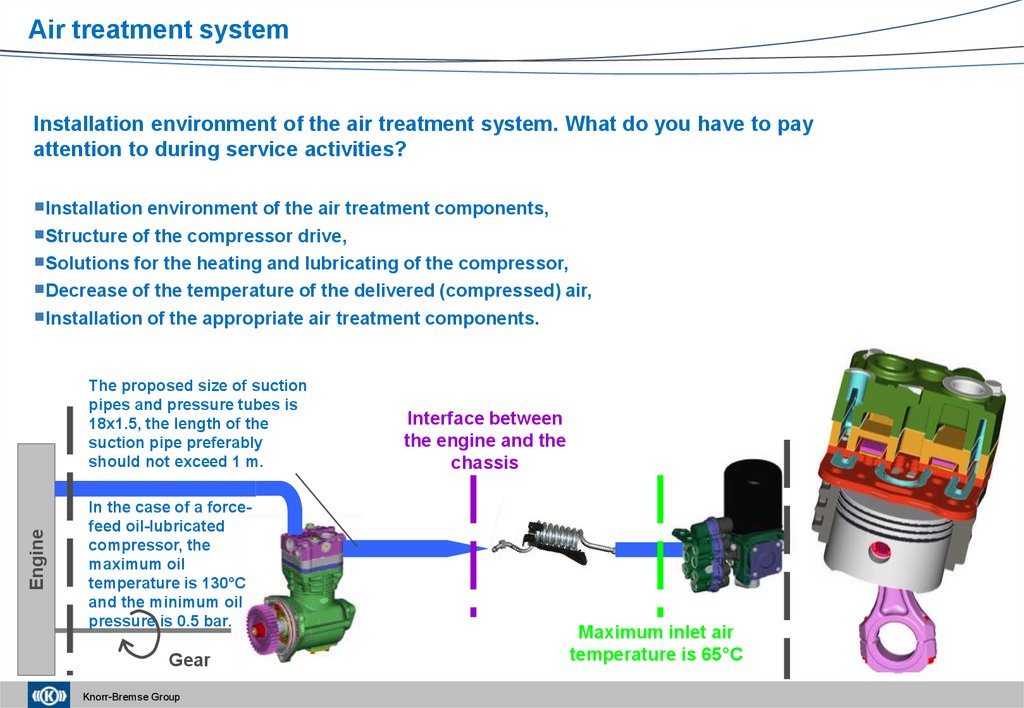
Air treatment systemInstallation environment of the air treatment system. What do you have to pay
attention to during service activities?
Installation environment of the air treatment components,
Structure of the compressor drive,
Solutions for the heating and lubricating of the compressor,
Decrease of the temperature of the delivered (compressed) air,
Installation of the appropriate air treatment components.
Engine
The proposed size of suction
pipes and pressure tubes is
18x1.5, the length of the
suction pipe preferably
should not exceed 1 m.
In the case of a forcefeed oil-lubricated
compressor, the
maximum oil
temperature is 130°C
and the minimum oil
pressure is 0.5 bar.
Gear
Knorr-Bremse Group
Interface between
the engine and the
chassis
Maximum inlet air
temperature is 65°C
7.
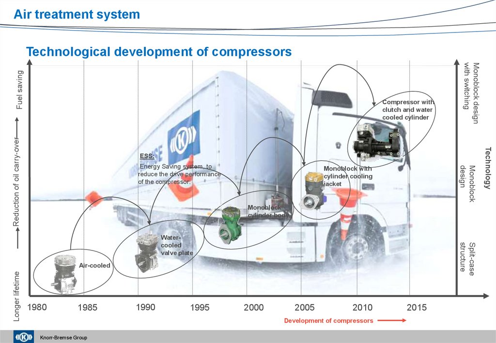
Air treatment systemESS:
Monoblock
design
Energy Saving system, to
reduce the drive performance
of the compressor.
Monoblock with
cylinder cooling
jacket
Monoblock
cylinder body
Split-case
structure
Watercooled
valve plate
Longer lifetime
Air-cooled
1980
1985
1990
1995
2000
2005
2010
Development of compressors
Knorr-Bremse Group
2015
Technology
Reduction of oil carry-over
Compressor with
clutch and water
cooled cylinder
Monoblock design
with switching
Fuel saving
Technological development of compressors
8.
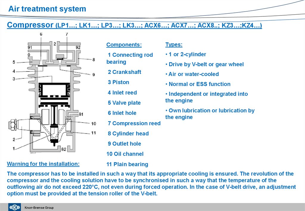
Air treatment systemCompressor (LP1…; LK1…; LP3…; LK3…; ACX6…; ACX7…; ACX8..; KZ3…;KZ4…)
Components:
Types:
1 Connecting rod
bearing
• 1 or 2-cylinder
2 Crankshaft
• Air or water-cooled
3 Piston
• Normal or ESS function
4 Inlet reed
• Independent or integrated into
the engine
5 Valve plate
6 Inlet hole
• Drive by V-belt or gear wheel
• Own lubrication or lubrication by
the engine
7 Compression reed
8 Cylinder head
9 Outlet hole
10 Oil channel
Warning for the installation:
11 Plain bearing
The compressor has to be installed in such a way that its appropriate cooling is ensured. The revolution of the
compressor and the cooling solution have to be synchronised in such a way that the temperature of the
outflowing air do not exceed 220°C, not even during forced operation. In the case of V-belt drive, an adjustment
option must be provided at the tension roller of the V-belt.
Knorr-Bremse Group
9.
Air treatment systemSuction phase
Knorr-Bremse Group
Delivery phase
10. Overview of the compressors
Air treatment systemOverview of the compressors
North America
European products
Tu-Flo 550™ &
Tu-Flo 750™
70 mm piston
80 mm piston
225 cc
single
cylinder
300 cc & 370 cc
twin cylinder
86 mm
piston
460 –
720 cc
twin
cylinder
Turbocharged
Version available
BA-921™
92 mm
piston
BA-922™
92 mm
piston
Turbocharged
version
available
720 cc
twin
cylinder
360 cc
single
cylinder
Knorr-Bremse Group
92 mm piston
360 cc
single
cylinder
92 mm
piston
650 –
720 cc
twin
cylinder
10
11.
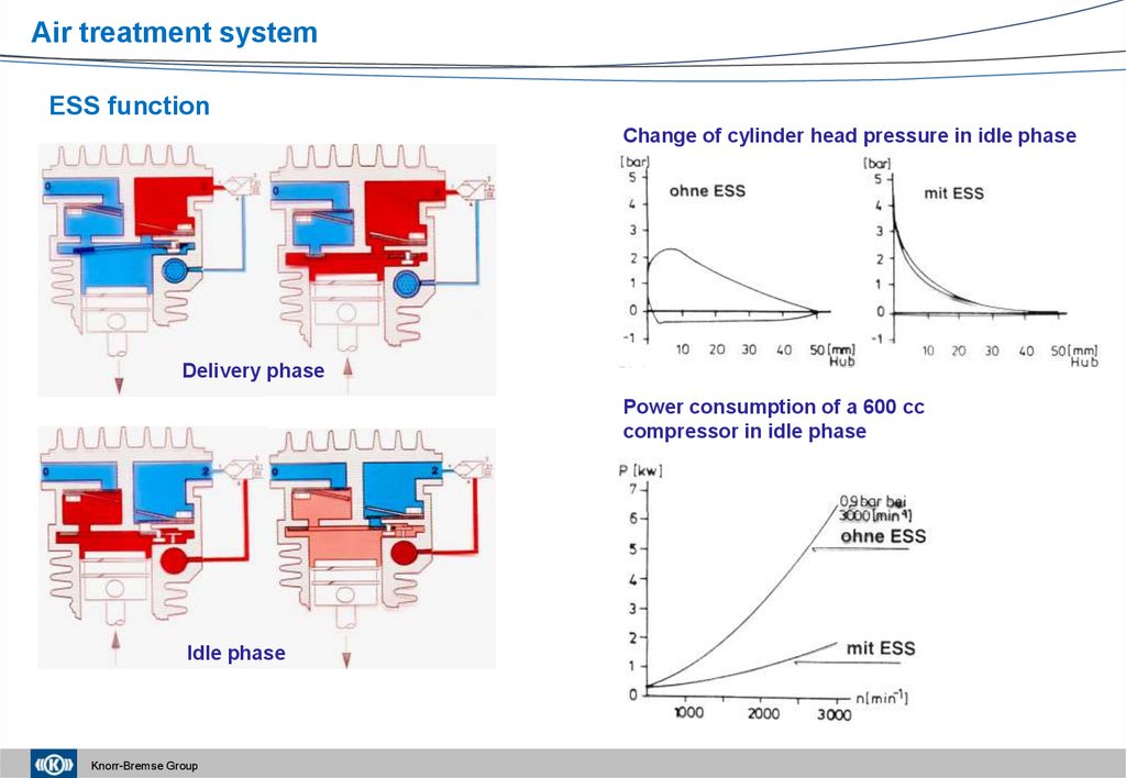
Air treatment systemESS function
Change of cylinder head pressure in idle phase
Delivery phase
Power consumption of a 600 cc
compressor in idle phase
Idle phase
Knorr-Bremse Group
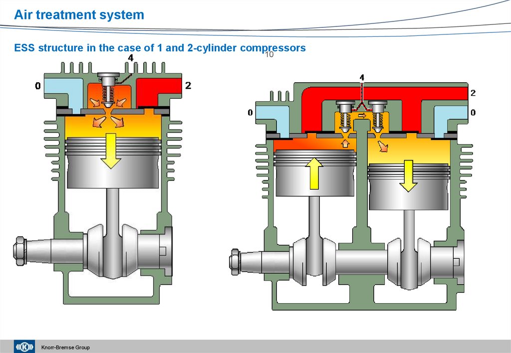
12. New ESS structure
Air treatment systemNew ESS structure
ESS is not active
ESS function is active
1.
Valve piston
Connectors:
2.
Valve seat
0 - Intake manifold
3.
Suction hole
2 – Exhaust manifold
4.
Compression spring
4 – Control connector
5.
Suction space
Knorr-Bremse Group
In the ESS phase the amount of air
delivered through the exhaust
manifold is reduced to about 15%
of the original amount.
13.
Air treatment systemESS structure in the case of 1 and 2-cylinder compressors
10
Knorr-Bremse Group
14. Development of the cylinder head structure – Reduction of the temperature of exhausted air
Air treatment systemDevelopment of the cylinder head structure – Reduction of the temperature of
exhausted air
Air-cooled
Water-cooled
Water-cooled cylinder head
+ valve plate
Super cooling
300
250
1980
2000
140
Super
coolin
g
100
Water
cooled
190
200
Air cooled
Delivered air
temperature [º C]
Temperature of supplied air
0
Knorr-Bremse Group
today
14
15. Development of the crankcase – Reduction of oil carry-over
Air treatment systemDevelopment of the crankcase – Reduction of oil carry-over
Split-case structure,
air-cooling
Split-case structure,
water-cooling
Monoblock
design
Monoblock design
and cooling jacket
3.0
Oil carry-over by cylinders
Monoblock
structure, cooling
jacket and
integrated switching
1.5
0.8
0.5
0.2
1980
Knorr-Bremse Group
1990
1995
2003
2006
15
0.1
2008
0.0
2010
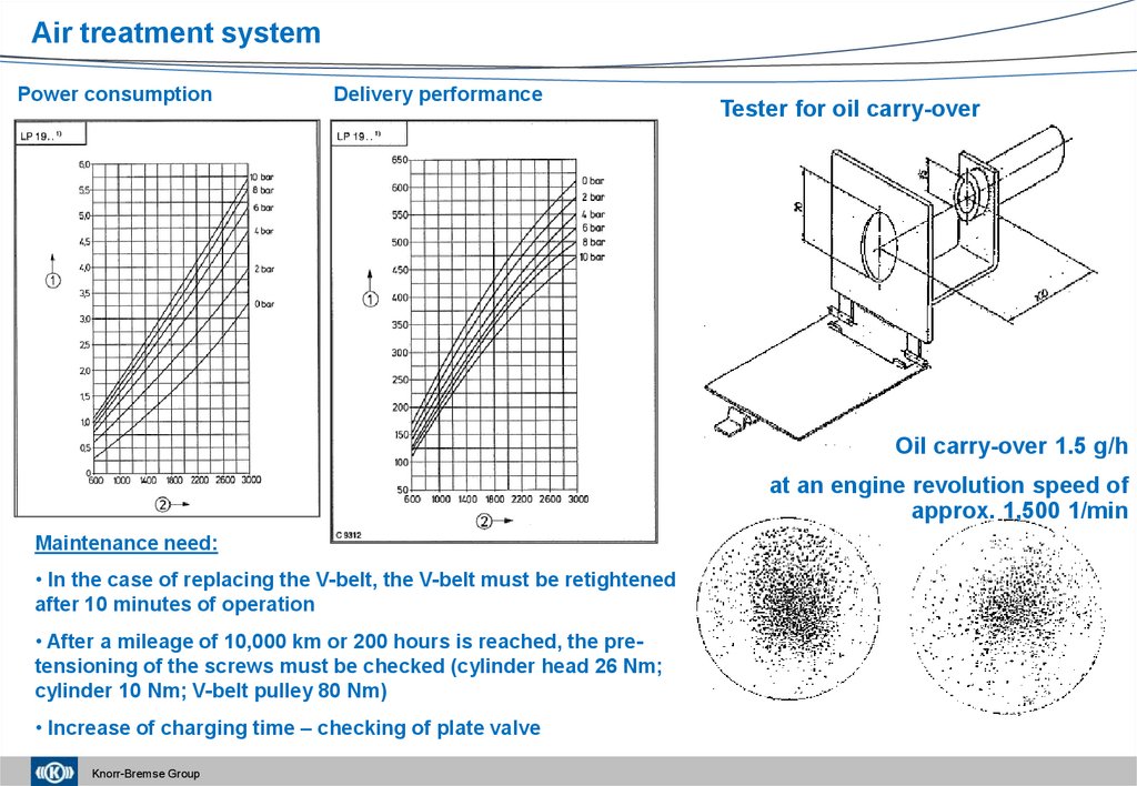
16.
Air treatment systemPower consumption
Delivery performance
Tester for oil carry-over
Oil carry-over 1.5 g/h
at an engine revolution speed of
approx. 1,500 1/min
Maintenance need:
• In the case of replacing the V-belt, the V-belt must be retightened
after 10 minutes of operation
• After a mileage of 10,000 km or 200 hours is reached, the pretensioning of the screws must be checked (cylinder head 26 Nm;
cylinder 10 Nm; V-belt pulley 80 Nm)
• Increase of charging time – checking of plate valve
Knorr-Bremse Group
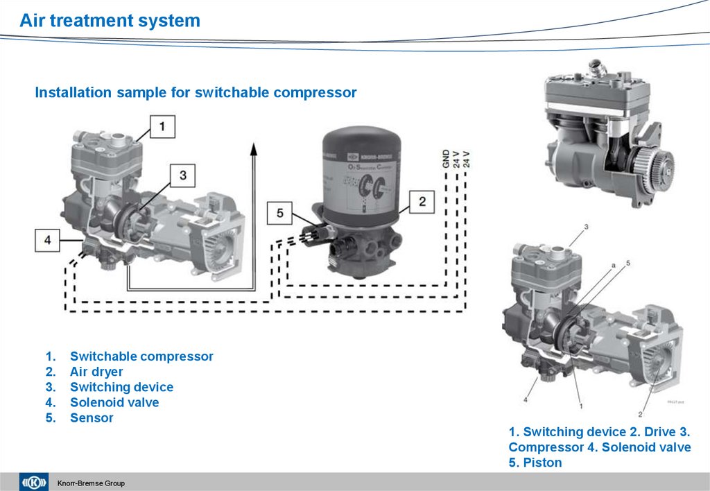
17.
Air treatment systemInstallation sample for switchable compressor
1.
2.
3.
4.
5.
Switchable compressor
Air dryer
Switching device
Solenoid valve
Sensor
1. Switching device 2. Drive 3.
Compressor 4. Solenoid valve
5. Piston
Knorr-Bremse Group
18.
Air treatment systemKnorr-Bremse Group
19.
Air treatment systemCompressors – Current service information
Knorr-Bremse Group
20.
Air treatment systemAutomatic alcohol injector (LA41..; 0 484 451 002 - 018):
Suggestions for application:
• Devices without a control connector (connector No. 4)
have to be installed before the unloader valve .
• Devices with a control connector have to be installed
after the unloader valve .
Suggestions for operation:
• Air reservoirs have to be drained regularly
• The reservoirs of the alcohol injector have to be filled
up at all times (it has to contain the minimum level
even in the summertime position)
• Suggested defrosting material: PAPAN SOFRO (out
of KB portfolio)
Knorr-Bremse Group
21.
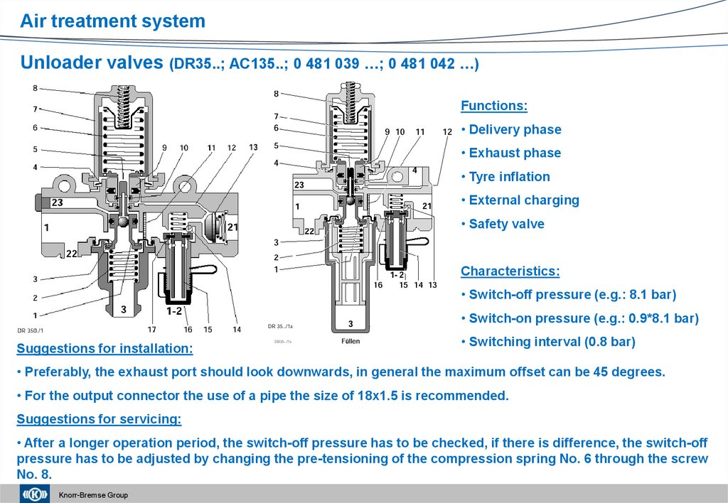
Air treatment systemUnloader valves (DR35..; AC135..; 0 481 039 …; 0 481 042 …)
Functions:
• Delivery phase
• Exhaust phase
• Tyre inflation
• External charging
• Safety valve
Characteristics:
• Switch-off pressure (e.g.: 8.1 bar)
• Switch-on pressure (e.g.: 0.9*8.1 bar)
Suggestions for installation:
• Switching interval (0.8 bar)
• Preferably, the exhaust port should look downwards, in general the maximum offset can be 45 degrees.
• For the output connector the use of a pipe the size of 18x1.5 is recommended.
Suggestions for servicing:
• After a longer operation period, the switch-off pressure has to be checked, if there is difference, the switch-off
pressure has to be adjusted by changing the pre-tensioning of the compression spring No. 6 through the screw
No. 8.
Knorr-Bremse Group
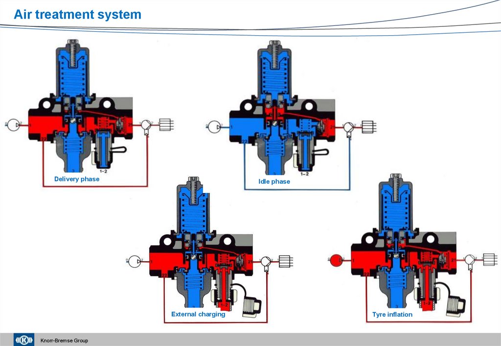
22.
Air treatment systemDelivery phase
Idle phase
External charging
Knorr-Bremse Group
Tyre inflation
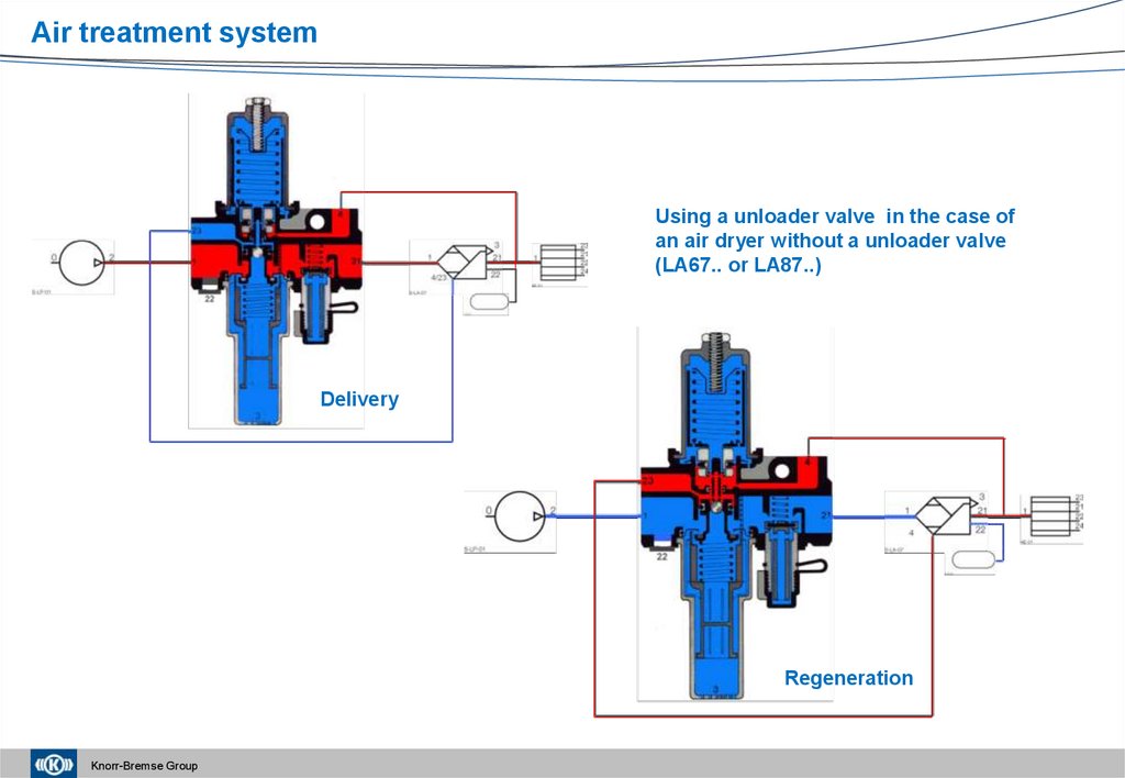
23.
Air treatment systemUsing a unloader valve in the case of
an air dryer without a unloader valve
(LA67.. or LA87..)
Delivery
Regeneration
Knorr-Bremse Group
24.
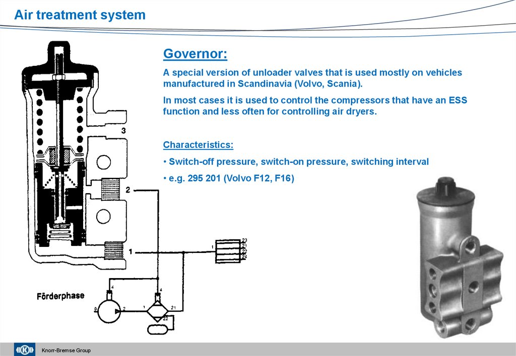
Air treatment systemGovernor:
A special version of unloader valves that is used mostly on vehicles
manufactured in Scandinavia (Volvo, Scania).
In most cases it is used to control the compressors that have an ESS
function and less often for controlling air dryers.
Characteristics:
• Switch-off pressure, switch-on pressure, switching interval
• e.g. 295 201 (Volvo F12, F16)
Knorr-Bremse Group
25.
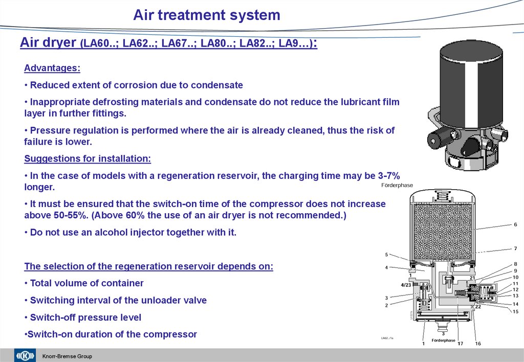
Air treatment systemAir dryer (LA60..; LA62..; LA67..; LA80..; LA82..; LA9…):
Advantages:
• Reduced extent of corrosion due to condensate
• Inappropriate defrosting materials and condensate do not reduce the lubricant film
layer in further fittings.
• Pressure regulation is performed where the air is already cleaned, thus the risk of
failure is lower.
Suggestions for installation:
• In the case of models with a regeneration reservoir, the charging time may be 3-7%
longer.
• It must be ensured that the switch-on time of the compressor does not increase
above 50-55%. (Above 60% the use of an air dryer is not recommended.)
• Do not use an alcohol injector together with it.
The selection of the regeneration reservoir depends on:
• Total volume of container
• Switching interval of the unloader valve
• Switch-off pressure level
•Switch-on duration of the compressor
Knorr-Bremse Group
26.
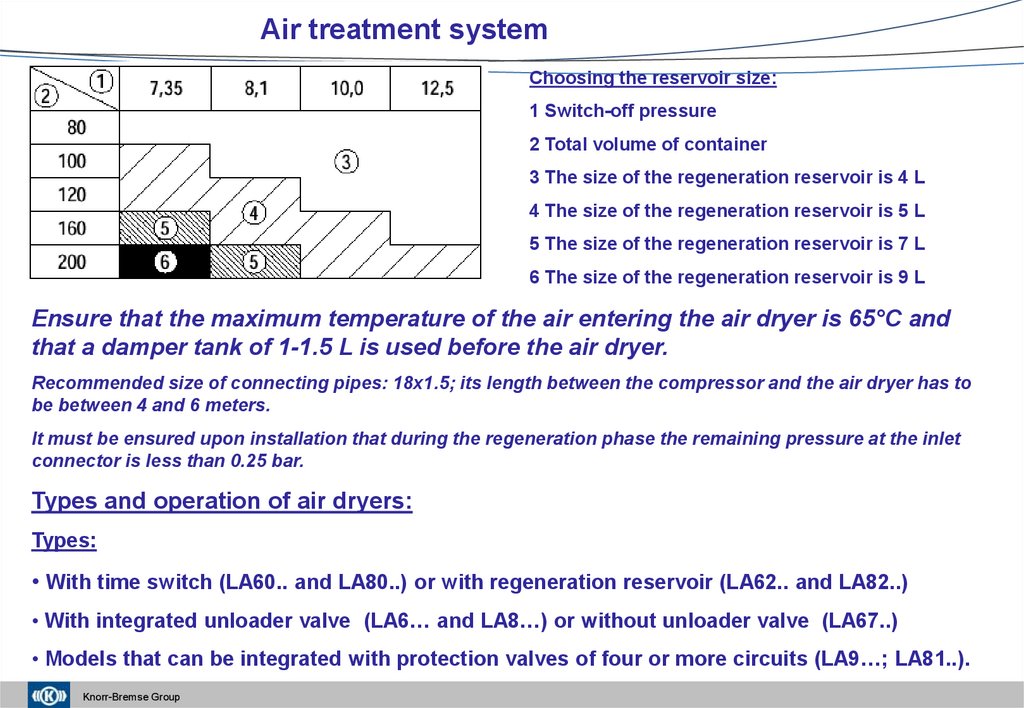
Air treatment systemChoosing the reservoir size:
1 Switch-off pressure
2 Total volume of container
3 The size of the regeneration reservoir is 4 L
4 The size of the regeneration reservoir is 5 L
5 The size of the regeneration reservoir is 7 L
6 The size of the regeneration reservoir is 9 L
Ensure that the maximum temperature of the air entering the air dryer is 65°C and
that a damper tank of 1-1.5 L is used before the air dryer.
Recommended size of connecting pipes: 18x1.5; its length between the compressor and the air dryer has to
be between 4 and 6 meters.
It must be ensured upon installation that during the regeneration phase the remaining pressure at the inlet
connector is less than 0.25 bar.
Types and operation of air dryers:
Types:
• With time switch (LA60.. and LA80..) or with regeneration reservoir (LA62.. and LA82..)
• With integrated unloader valve (LA6… and LA8…) or without unloader valve (LA67..)
• Models that can be integrated with protection valves of four or more circuits (LA9…; LA81..).
Knorr-Bremse Group
27.
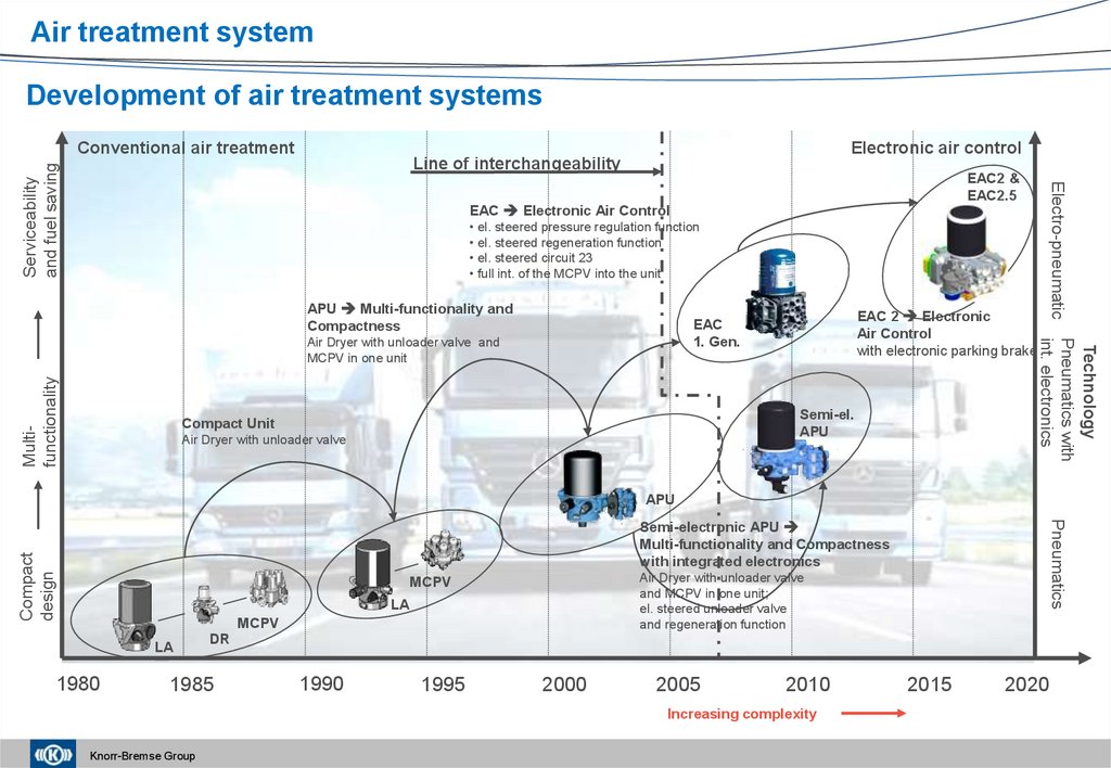
Air treatment systemDevelopment of air treatment systems
Conventional air treatment
Electronic air control
EAC2 &
EAC2.5
EAC Electronic Air Control
• el. steered pressure regulation function
• el. steered regeneration function
• el. steered circuit 23
• full int. of the MCPV into the unit
APU Multi-functionality and
Compactness
Multifunctionality
Air Dryer with unloader valve and
MCPV in one unit
Semi-el.
APU
Compact Unit
Air Dryer with unloader valve
Technology
Pneumatics with
int. electronics
EAC 2 Electronic
Air Control
with electronic parking brake
EAC
1. Gen.
Electro-pneumatic
Serviceability
and fuel saving
Line of interchangeability
APU
Pneumatics
Compact
design
Semi-electronic APU
Multi-functionality and Compactness
with integrated electronics
Air Dryer with unloader valve
and MCPV in one unit;
el. steered unloader valve
and regeneration function
MCPV
LA
MCPV
LA
1980
DR
1985
1990
1995
2000
2005
2010
Increasing complexity
Knorr-Bremse Group
2015
2020
28.
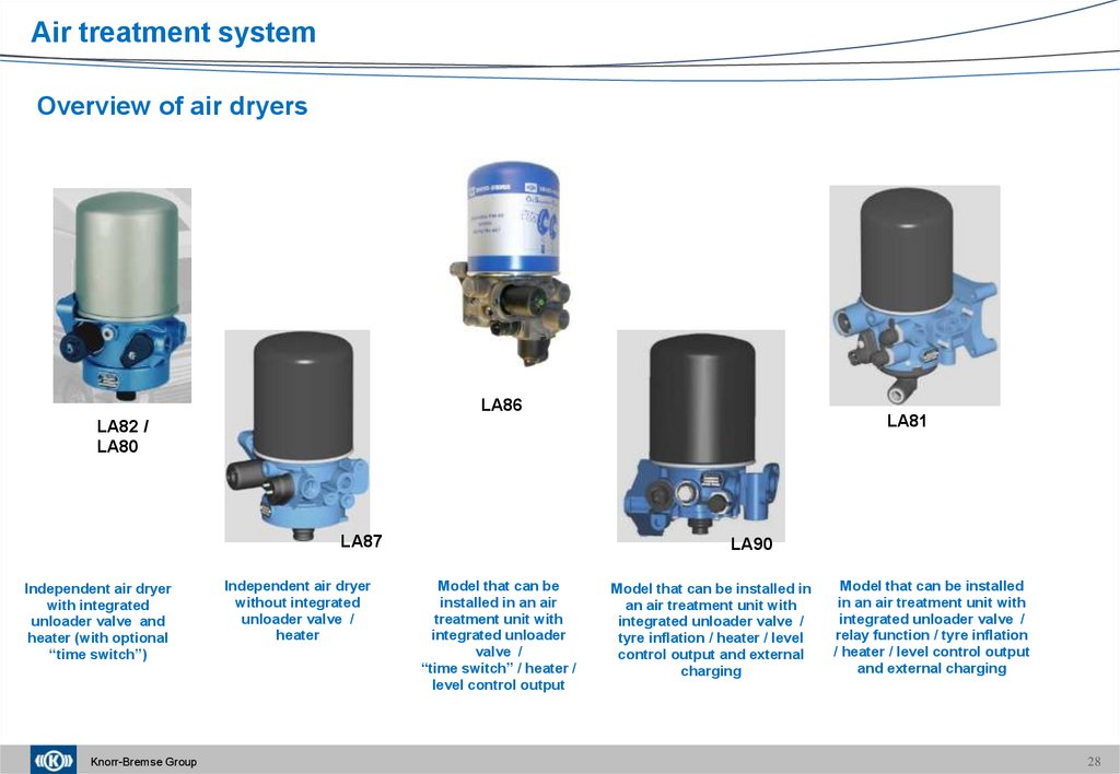
Air treatment systemOverview of air dryers
LA86
LA81
LA82 /
LA80
LA87
Independent air dryer
with integrated
unloader valve and
heater (with optional
“time switch”)
Knorr-Bremse Group
Independent air dryer
without integrated
unloader valve /
heater
LA90
Model that can be
installed in an air
treatment unit with
integrated unloader
valve /
“time switch” / heater /
level control output
Model that can be installed in
an air treatment unit with
integrated unloader valve /
tyre inflation / heater / level
control output and external
charging
Model that can be installed
in an air treatment unit with
integrated unloader valve /
relay function / tyre inflation
/ heater / level control output
and external charging
28
29.
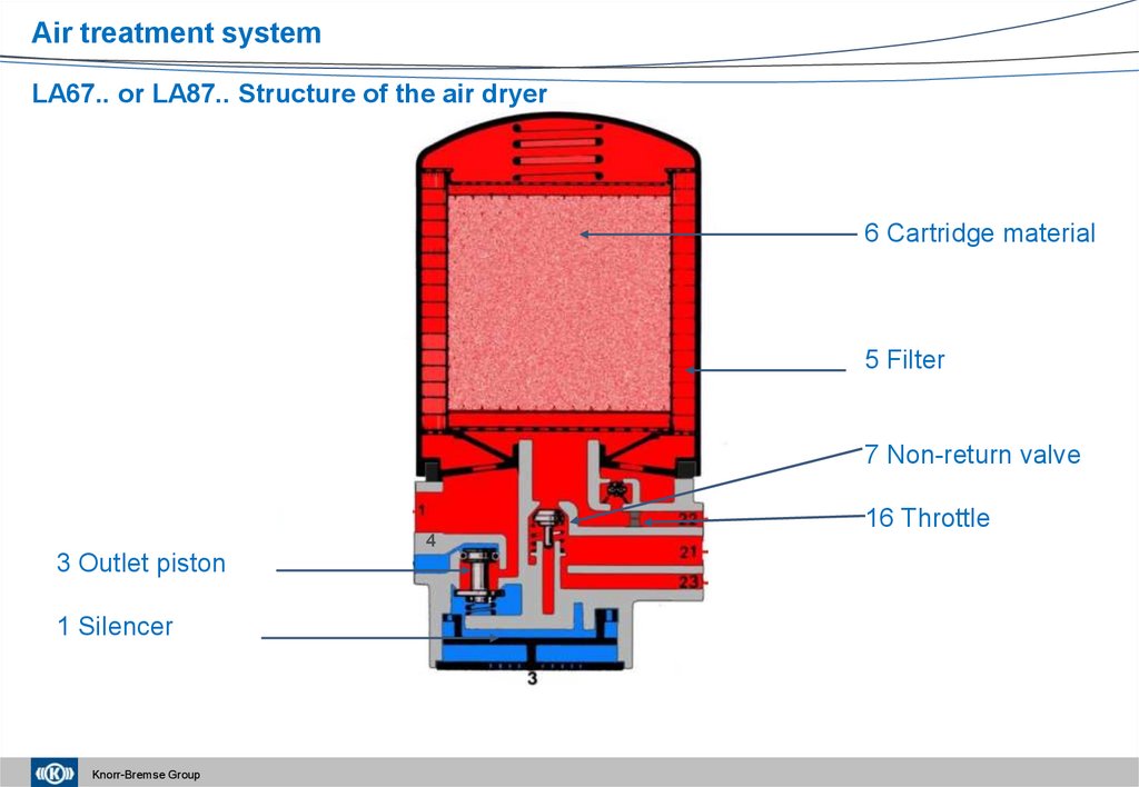
Air treatment systemLA67.. or LA87.. Structure of the air dryer
6 Cartridge material
5 Filter
7 Non-return valve
16 Throttle
4
3 Outlet piston
1 Silencer
Knorr-Bremse Group
30.
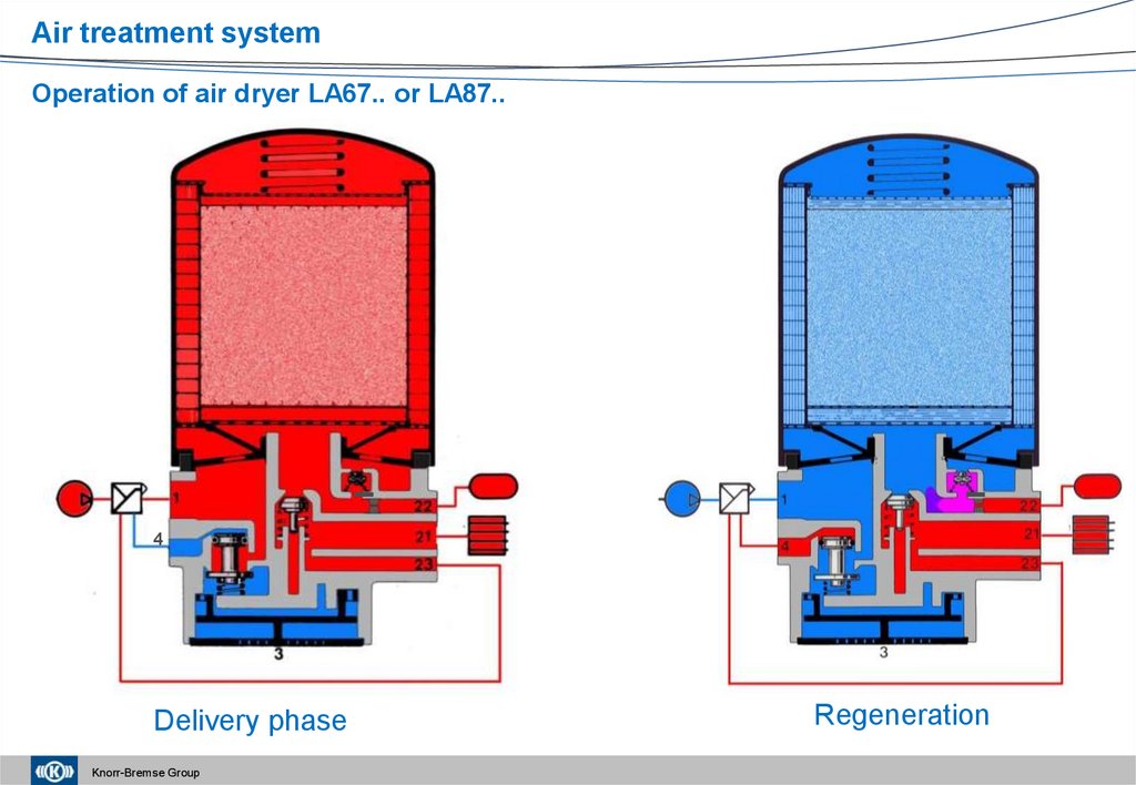
Air treatment systemOperation of air dryer LA67.. or LA87..
4
Delivery phase
Knorr-Bremse Group
Regeneration
31.
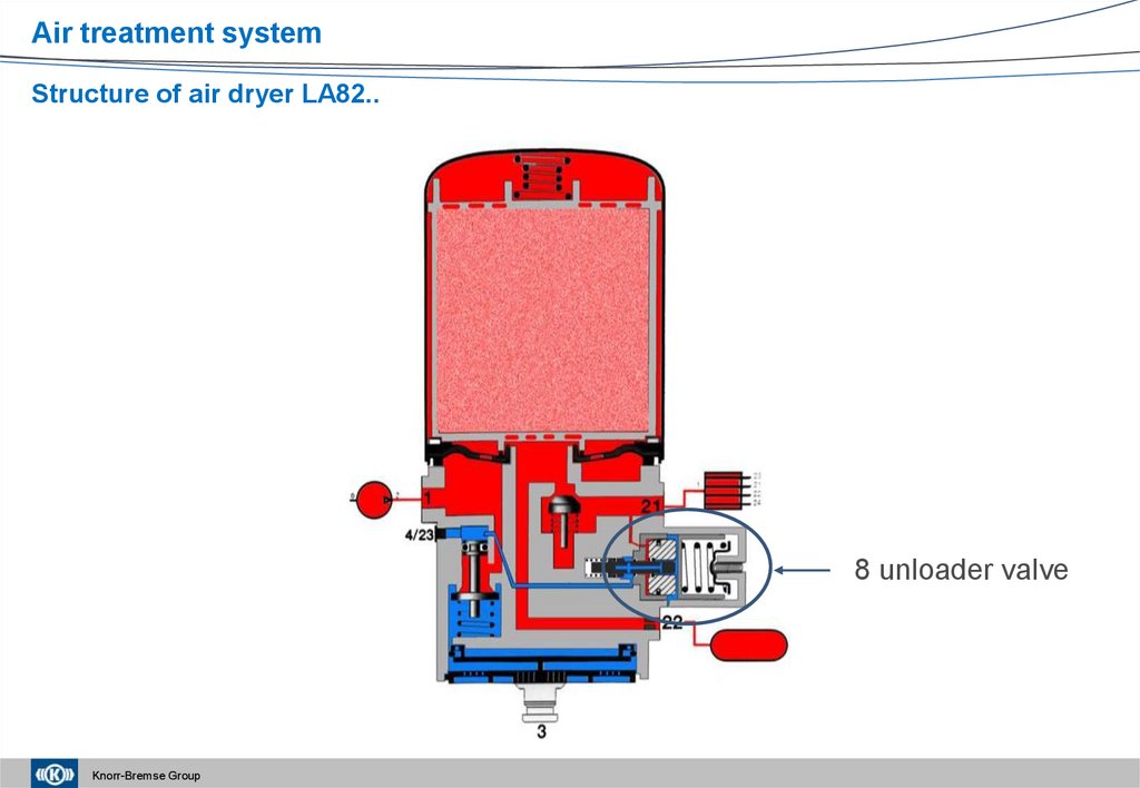
Air treatment systemStructure of air dryer LA82..
8 unloader valve
Knorr-Bremse Group
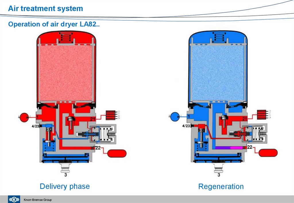
32.
Air treatment systemOperation of air dryer LA82..
Delivery phase
Knorr-Bremse Group
Regeneration
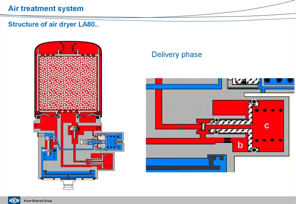
33.
Air treatment systemStructure of air dryer LA80..
Delivery phase
c
b
Knorr-Bremse Group
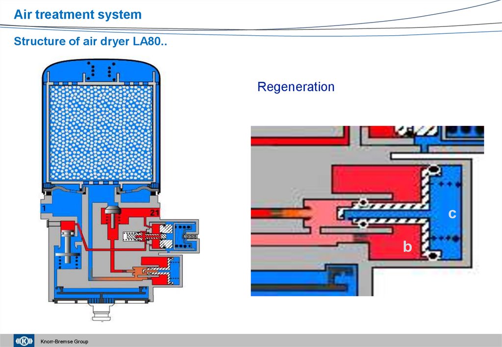
34.
Air treatment systemStructure of air dryer LA80..
Regeneration
c
b
Knorr-Bremse Group
35. Air dryer LA9… and LA81.. for the complex air processing units APU (ZB45..; ZB47..)
Air treatment systemAir dryer LA9… and LA81.. for the complex air processing units APU (ZB45..; ZB47..)
LA9…
LA81..
Delivery phase
Regeneration phase
Knorr-Bremse Group
36. Semi-electronic air dryer (EL9…) Cartridges and heaters
Air treatment systemSemi-electronic air dryer (EL9…)
• Intelligent pressure regulation and regeneration
control by the central electronics of the vehicle,
• It performs the commands of the vehicle
electronics with the help of two electromagnets,
• It is a model that can be installed in a complex air
processing unit (ZE45../ ZE46..).
Cartridges and heaters
• Cartridges can have left or right thread,
• Cartridges can have different sizes,
• They can have a traditional or an oil
separation structure.
Heater connectors can have
different electric connectors.
They have a performance of
100 W, switching on below 5°C
and switching off above 27°C.
Knorr-Bremse Group
36
37.
Air treatment systemAuxiliary equipment:
Drain valve
EE 4206
Silencers
Threaded design
EE 4203
Snap catch design
Knorr-Bremse Group
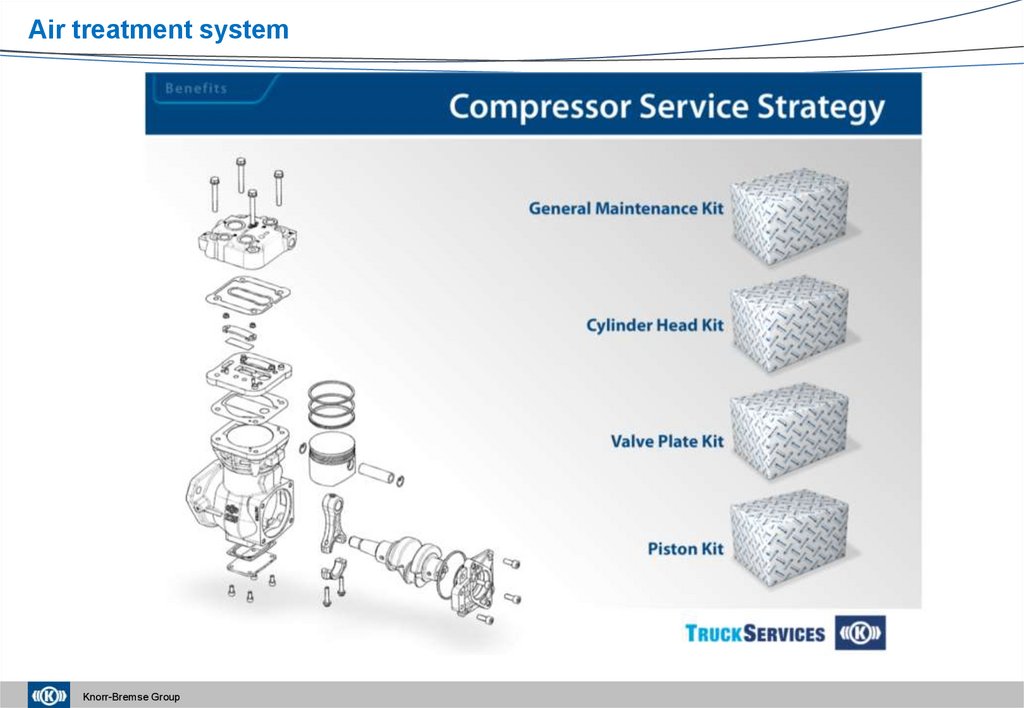
38. Service Strategy
Air treatment systemService Strategy
Complete Product
Cartridge
Repair Sets
Service Kit
time switch
(5)
Cartridge (2)
OE Product
AM LA (1)
with cartridge
Service Kit
complete
(6)
Service Manual / Film and Documentation
Silencer (3)
Knorr-Bremse Group
Heater (4)
For a quick replacement and service of subassemblies
and components in accordance with high safety
requirements.
39. Service Strategy
Air treatment systemService Strategy
Complete Product
Cartridge and Sensor
Cartridge (4)
Repair Sets
Double
Pressure
Sensor (5)
Tyre Inflator Valve (8)
IAM LA (1)
Rationalised
with sealings
OE Product
Solenoid Unit (9)
2a
IAM MCPV (2)
with sealings
Heater (7)
2b
Knorr-Bremse Group
Silencer (6)
Service Manual / Film and Documentation
For a quick replacement and service of subassemblies
and components in accordance with high safety
requirements.
40.
Air treatment systemAir dryer units – Current service information
Knorr-Bremse Group
41.
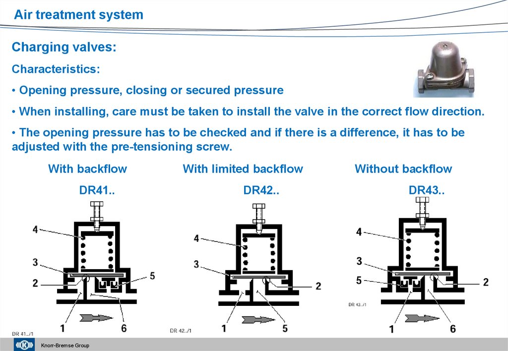
Air treatment systemCharging valves:
Characteristics:
• Opening pressure, closing or secured pressure
• When installing, care must be taken to install the valve in the correct flow direction.
• The opening pressure has to be checked and if there is a difference, it has to be
adjusted with the pre-tensioning screw.
With backflow
DR41..
Knorr-Bremse Group
With limited backflow
DR42..
Without backflow
DR43..
42. Charging valve with limited backflow (DR42..)
Air treatment systemCharging valve with limited backflow (DR42..)
Charging
Connector 1 pressure-free
Knorr-Bremse Group
At the end of charging
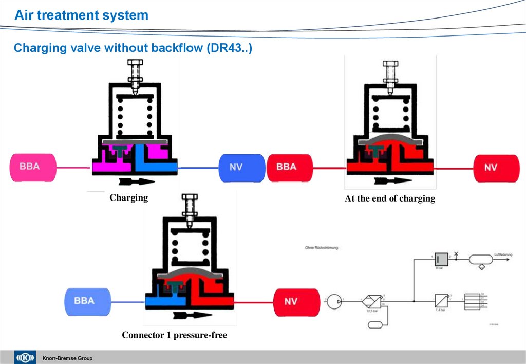
43.
Air treatment systemCharging valve without backflow (DR43..)
Charging
Connector 1 pressure-free
Knorr-Bremse Group
At the end of charging
44.
Air treatment systemCharging valve with backflow (DR41..)
Charging
Pressure fall on connector 1
Knorr-Bremse Group
At the end of charging
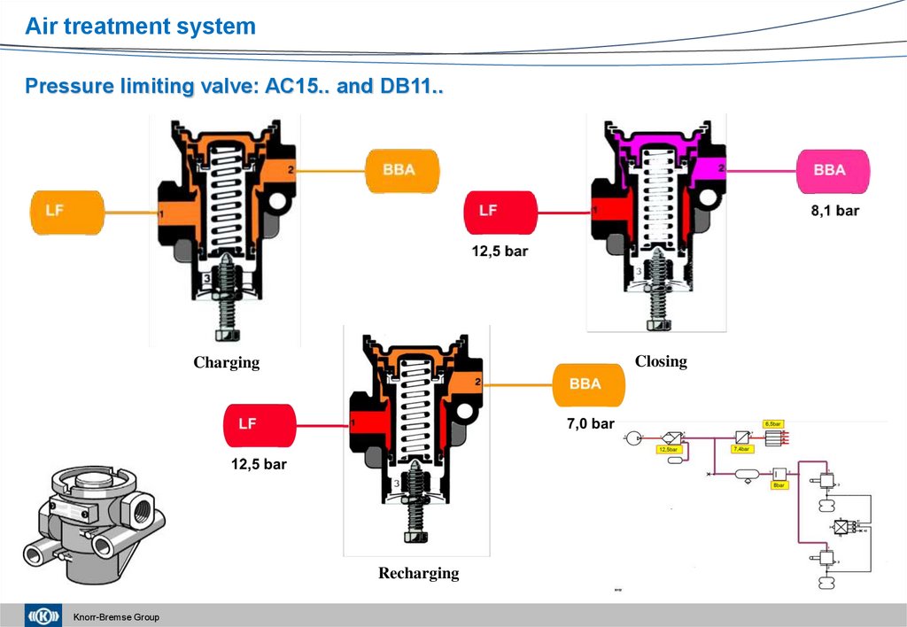
45.
Air treatment systemPressure limiting valve: AC15.. and DB11..
Closing
Charging
Recharging
Knorr-Bremse Group
46.
Air treatment systemThe four-circuit protection valve (AE41..; AE44..; AE45..; AE46..; AE48…):
Its function:
Ensuring the so-called priority order during the charging of the air system.
If a circuit is damaged, ensuring the separation of the damaged circuit from the undamaged
circuits.
Characteristics:
• Opening pressures of the circuits (order of opening)
• Static closing pressure (dynamic closing pressure): The pressure level at which the damaged
circuit closes (the diaphragm valves close), if the compressor is not delivering.
• The secured pressure: The pressure level that is present in the undamaged circuits when the
compressor is delivering continuously, which is the same as the opening pressure of the
damaged circuit.
Knorr-Bremse Group
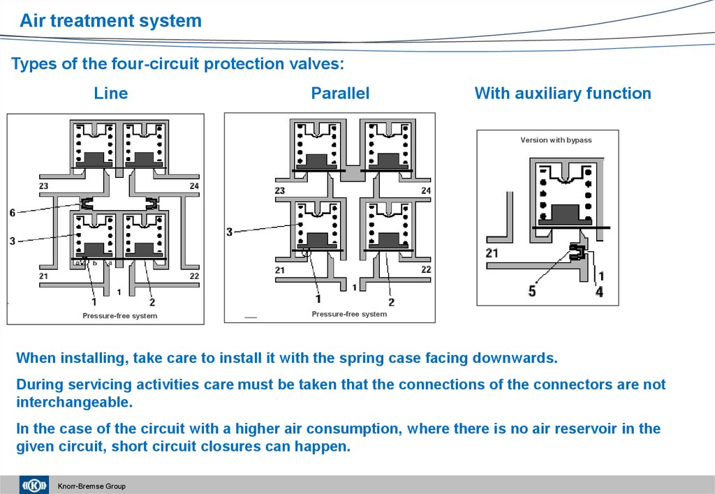
47.
Air treatment systemTypes of the four-circuit protection valves:
Line
Parallel
With auxiliary function
Version with bypass
Pressure-free system
Pressure-free system
When installing, take care to install it with the spring case facing downwards.
During servicing activities care must be taken that the connections of the connectors are not
interchangeable.
In the case of the circuit with a higher air consumption, where there is no air reservoir in the
given circuit, short circuit closures can happen.
Knorr-Bremse Group
48.
Air treatment systemParallel four-circuit protection valve (AE4170)
without priority
Pressure-free system
Knorr-Bremse Group
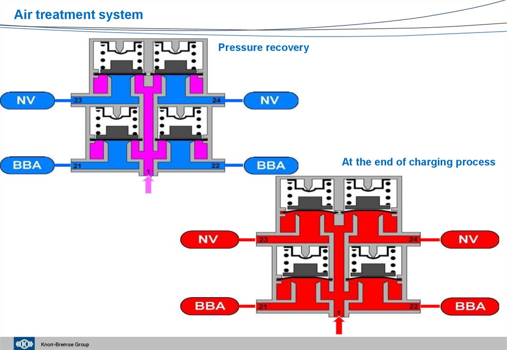
49.
Air treatment systemPressure recovery
At the end of charging process
1
1
Knorr-Bremse Group
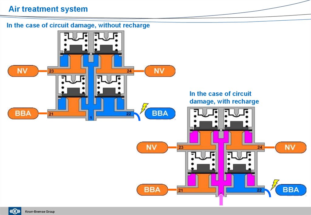
50.
Air treatment systemIn the case of circuit damage, without recharge
In the case of circuit
damage, with recharge
BBA
BBA
Knorr-Bremse Group
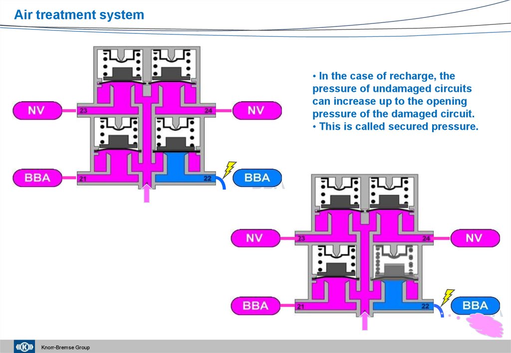
51.
Air treatment system• In the case of recharge, the
pressure of undamaged circuits
can increase up to the opening
pressure of the damaged circuit.
• This is called secured pressure.
BBA
BBA
Knorr-Bremse Group
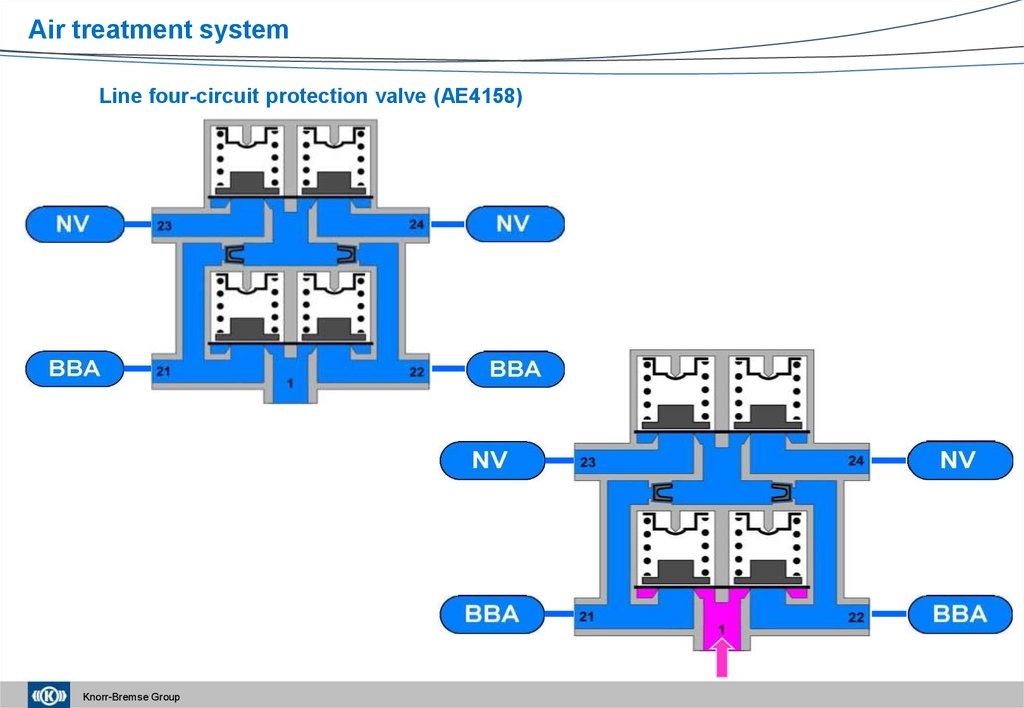
52.
Air treatment systemLine four-circuit protection valve (AE4158)
Knorr-Bremse Group
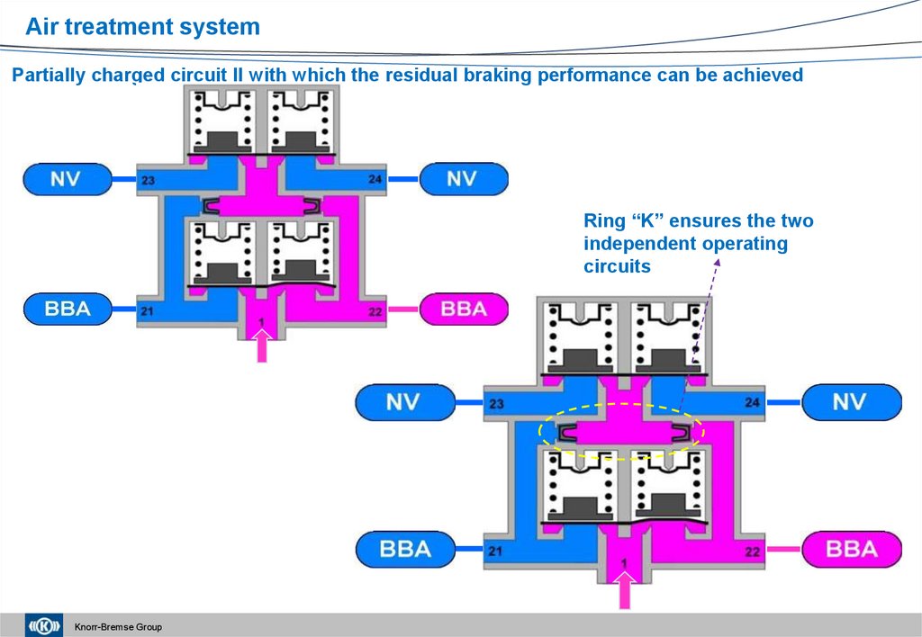
53.
Air treatment systemPartially charged circuit II with which the residual braking performance can be achieved
Ring “K” ensures the two
independent operating
circuits
Knorr-Bremse Group
54.
Air treatment systemCharged operating circuits
Fully charged system
Knorr-Bremse Group
55.
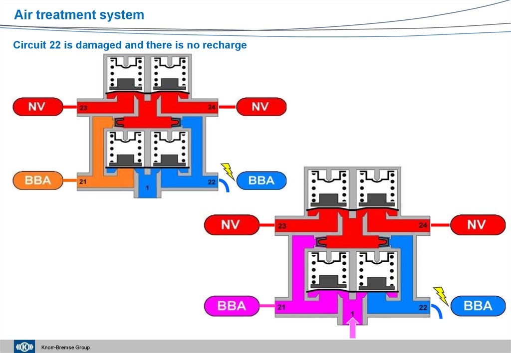
Air treatment systemCircuit 22 is damaged and there is no recharge
Knorr-Bremse Group
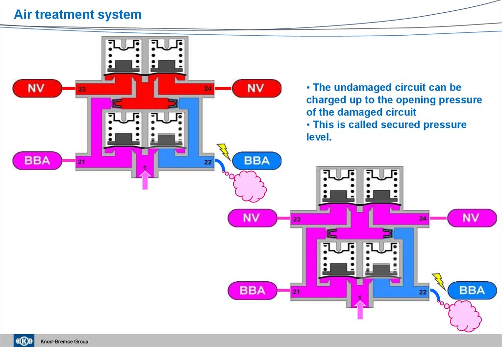
56.
Air treatment system• The undamaged circuit can be
charged up to the opening pressure
of the damaged circuit
• This is called secured pressure
level.
Knorr-Bremse Group
57.
Air treatment systemWith a damaged operating circuit, the system cannot be charged if the
opening pressure of the damaged circuit is low
The system can be charged
with the help of a bypass
Knorr-Bremse Group
58. New four-circuit protection valves according to EG-R 98/12 (AE46..; AE48.. )
Air treatment systemNew four-circuit protection valves according to EG-R 98/12 (AE46..; AE48.. )
1
In the case of a damaged operating brake circuit, an operated parking brake system can
only be released if the pressure in the operating brake system will once again reach the
level of the residual braking performance (13%) (RREG 98/12).
This is ensured with the help of a throttle valve (see Arrow 1) that releases the pressure from the operating
brake circuit into the open through Connector 3 (see Arrow 2). This can be clearly heard, it is not a malfunction
of the valve.
Thus, as a prerequisite, there should be a pressure reduction in the operating brake circuit.
The throttle valve can be controlled from both operating brake circuits No. 1 and 2.
Knorr-Bremse Group
59. Charging of the system
Air treatment systemCharging of the system
24
23
24
23
21
22
1
21
Knorr-Bremse Group
1
22
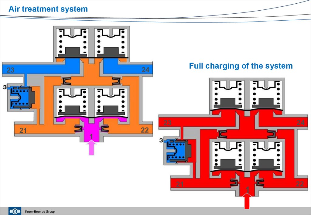
60.
Air treatment systemFull charging of the system
24
23
24
23
21
1
22
21
Knorr-Bremse Group
1
22
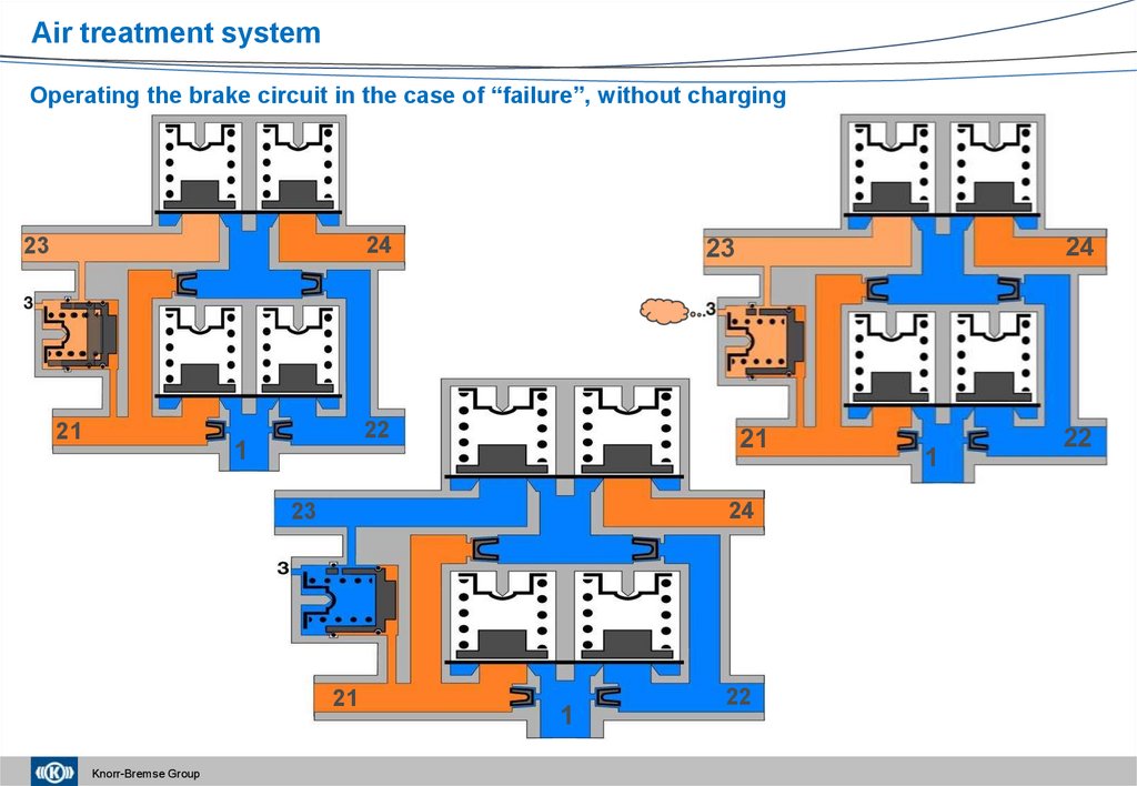
61.
Air treatment systemOperating the brake circuit in the case of “failure”, without charging
24
23
21
22
1
21
24
23
21
Knorr-Bremse Group
24
23
1
22
1
22
62. Multi-circuit protection valves
Air treatment systemMulti-circuit protection valves
AE46
AE48
Independent or can be
installed in an air
treatment unit with
integrated exhaust
valve
● 4 outlet connectors
● Optionally: Dual
pressure sensor
Knorr-Bremse Group
Independent or can be
installed in an air
treatment unit with
integrated exhaust valve
● 8 outlet connectors
● With a pressure
limiting valve for back
circuits
● Optionally: Dual
pressure sensor
AE45 /47
Independent or can be
installed in an air treatment
unit with integrated exhaust
valve
● Max. 9 outlet connectors
● Max. two pressure limiting
options for the front and
back circuits
● Optionally: Dual pressure
sensor
62
63.
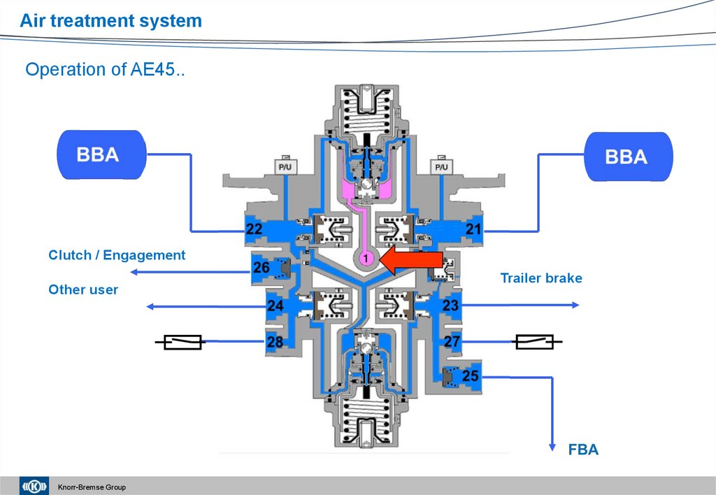
Air treatment systemOperation of AE45..
Clutch / Engagement
Other user
Knorr-Bremse Group
Trailer brake
64.
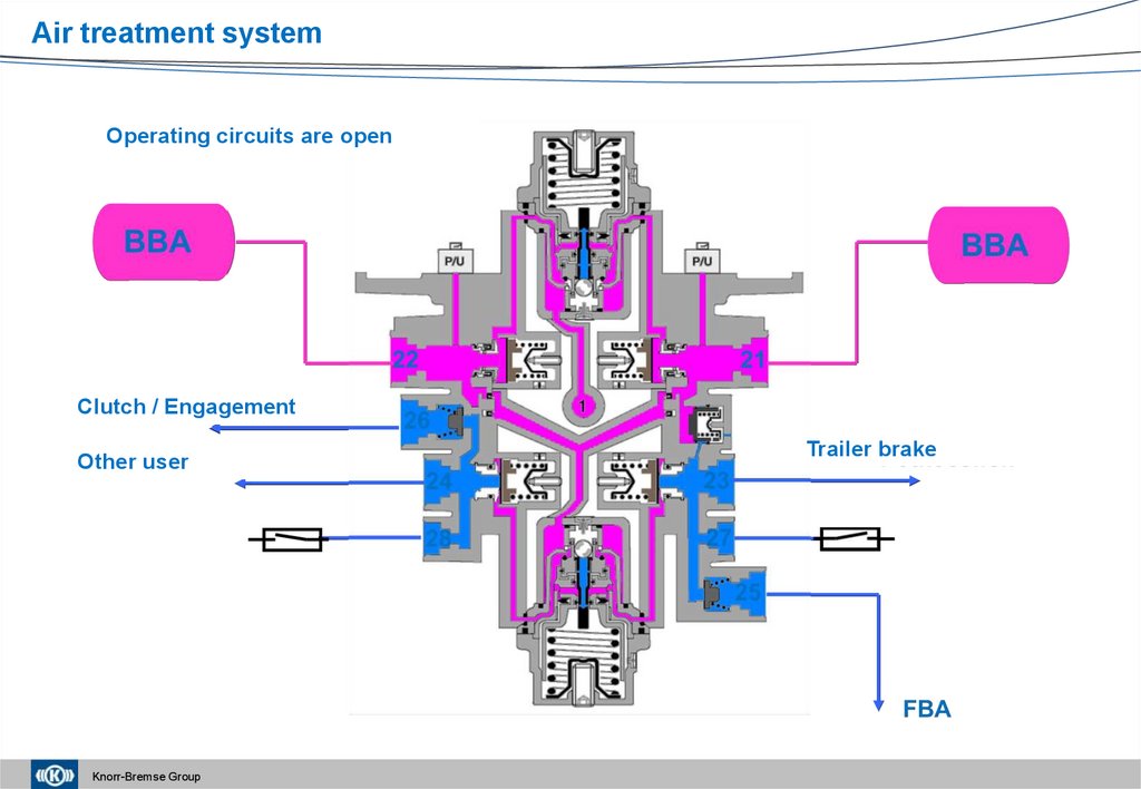
Air treatment systemOperating circuits are open
Clutch / Engagement
Other user
Knorr-Bremse Group
Trailer brake
65.
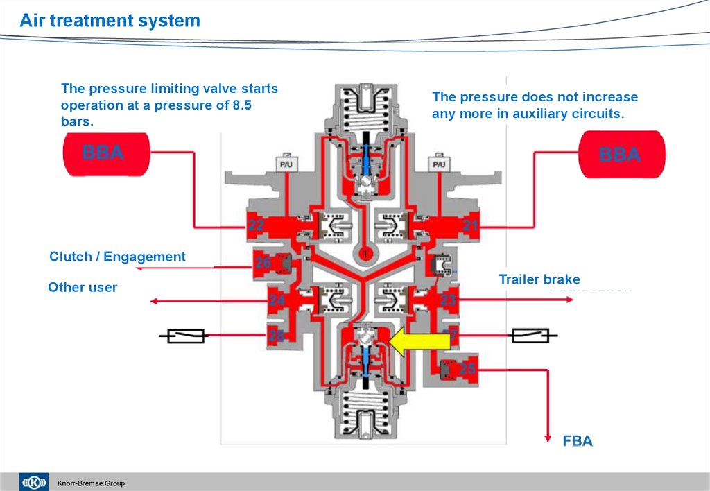
Air treatment systemThe pressure limiting valve starts
operation at a pressure of 8.5
bars.
The pressure does not increase
any more in auxiliary circuits.
Clutch / Engagement
Other user
Knorr-Bremse Group
Trailer brake
66.
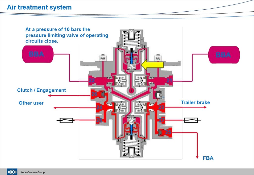
Air treatment systemAt a pressure of 10 bars the
pressure limiting valve of operating
circuits close.
Clutch / Engagement
Other user
Knorr-Bremse Group
Trailer brake
67.
Air treatment systemPressure level of inlet connector
reaches 12.5 bars.
Clutch / Engagement
Other user
Knorr-Bremse Group
Trailer brake
68.
Air treatment systemFour-circuit protection valves – Current service information
Knorr-Bremse Group
69.
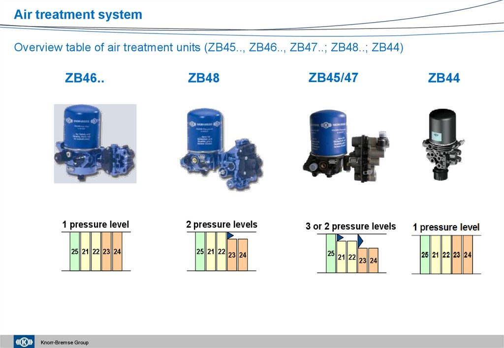
Air treatment systemOverview table of air treatment units (ZB45.., ZB46.., ZB47..; ZB48..; ZB44)
ZB46..
ZB46
ZB48
ZB45/47
ZB44
ZB48
ZB45
1 pressure level
2 pressure levels
3 or 2 pressure levels
25 21 22 23 24
25 21 22 23 24
25 21 22
Optional features: EG function, ESS, heater, tyre inflator, external filling port
Customers: MAN, DAF, Daimler, Iveco, Isuzu
Classic high volume products: standard applications at reasonable costs
Knorr-Bremse Group
23 24
70.
Air treatment systemComplex air treatment units – Current service information
Knorr-Bremse Group
71.
Air treatment systemSummary of necessary service activities:
Compressor:
•condition of air filter
•condition of suction pipe
•tension of V-belt
•condition of pressure tube
•air delivery
•oil carry-on
•exhausted air temperature
unloader valve
•Controlling the switch-off pressure
•Controlling the switching interval
Air dryer:
•Quantity of condensate in air reservoirs
•Condition of the cartridge
•Controlling the switch-off pressure
•Controlling the switching interval
•Percentage of delivery and regeneration phases
•In the case of cartridge replacement, the cartridges of appropriate thread size and thread
direction must be used
Knorr-Bremse Group