


 industry
Similar presentations:


Swisscross tutti. En assembly manual
1.
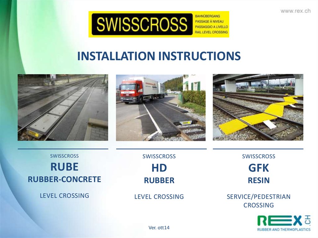
INSTALLATION INSTRUCTIONSSWISSCROSS
SWISSCROSS
SWISSCROSS
RUBE
HD
GFK
RUBBER-CONCRETE
RUBBER
RESIN
LEVEL CROSSING
LEVEL CROSSING
SERVICE/PEDESTRIAN
CROSSING
Ver. ott14
2.
«SWISSCROSS RUBE»RUBBER-CONCRETE
LEVEL CROSSING
INSTALLATION INSTRUCTIONS
Ver. ott14
Rail & Road – Technique ferroviaire August 2014
3.
Rubber-concrete level crossing«SWISSCROSS RUBE»
gauge: 1000 – 1435 – 1524 – 1600 mm
Advantages
Best vibration damping and noise reduction
More Load resistance and less deformation to the passage of heavy vehicles
Quick and rational assembling
Better resistance and durability
Best behavior with frosting and rain
High stability
Ensure electrical isolation between the two rails
Ver. ott14
4.
Rubber-concrete level crossing«SWISSCROSS RUBE»
gauge: 1000 – 1435 – 1524 – 1600 mm
INSTALLATION INSTRUCTIONS
Level crossing system with open groove (distance 1000, 1435 et 1524 mm)
1. USE
2. NECESSARY EQUIPEMENT AND TOOLS FOR INSTALLATION
3. INSTALLATION
3.1 Préparation of basement
3.2 Construction of elements
3.3 Installation of the side elements
4. MAINTENANCE
4.1 Care during winter
4.2 Installation and Dismantling
Technical advices and sales by Rex Articoli Tecnici SA
Ver. ott14
5.
Installation Instructions«SWISSCROSS RUBE»
INSTALLATION INSTRUCTION FOR SWISSCROSS PASSAGE AT RUBE
1. USE
This statement relates to the execution of «SWISSCROSS RUBE» passage level in rubber-concrete.
The «SWISSCROSS RUBE» passage can only be mounted on concrete sleeper with a distance of 600 +/- 10mm between the sleepers.
There are different models depending on the type of rail. Before starting the installation check the equipment, particularly the
correspondence between the type of sleeper and the path with the elements provided. The checklist compiled under command can
help. If the assembly provides the installation of concrete curbs this must be arranged in advance. Installing the asphalt connection
to the wheel must be organised to be done just after laying the PN. The « dettaglio bordura » form explains the correct installation
of these elements.
Ver. ott14
6.
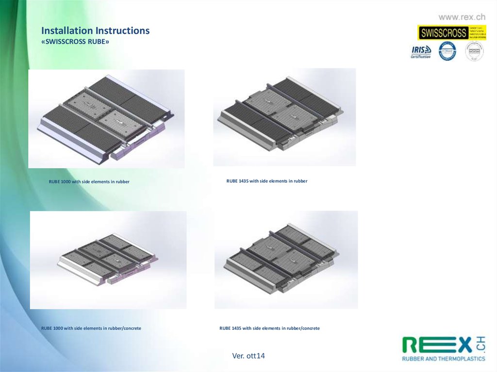
Installation Instructions«SWISSCROSS RUBE»
RUBE 1000 with side elements in rubber
RUBE 1000 with side elements in rubber/concrete
RUBE 1435 with side elements in rubber
RUBE 1435 with side elements in rubber/concrete
Ver. ott14
7.
Installation Instructions«SWISSCROSS RUBE»
2. NECESSARY EQUIPMENTS AND TOOLS FOR INSTALLATION (see attached list)
- Power driven lifting wagon to lift the concrete elements and press them into rubber elements
- Pegs to lift the rubber and concrete elements, metal bars to bend the rubber elements (Rube 1000)
- Grease
- Agitator to vibrate the ballast, shovel
- Knocker, hammer
- Grease protective bolts
- Cordless screwdriver, impact driver
- 2 24mm polygonal keys, 1 13mm polygonal key. Socket wrench
The installation of a 9 meters PN to 5 persons is calculated at 6 o’clock, with installation of concrete curbs.
3. INSTALLATION
3.1 Preparation of basement and Installation of supporting elements
The destination of the level passage should be marked by ensuring the rubber elements are 50 cm wider than the floor
Sometimes the passages are built diagonally. The spacing should be done as follows (recommendation): when the slope of the road
exceed 80° there is nothing to respect. With an angle of 70 - 80° it is recommended to cover an additional sleeper and at an
angle below 70° it is recommended to cover two more sleepers.
Ver. ott14
8.
Installation Instructions«SWISSCROSS RUBE»
In the area of the level passage you need to enclose the old filling outside the rails for 70cm until the end of the sleepers. When it is
not possible to stop the flow the installation must be done in two or several sections. In some cases it is necessary to strengthen the
sleepers with a vibrator. The distance between the sleepers must be 600 +/- 10mm from the center of the sleeper, and 4 x 600 mm
should be 2,400 mm +/- 30mm. When it is necessary to strengthen the sleepers it is recommended to do so before the installation.
At the risk of water alluvium under or in the level passage area it is necessary to install a forward flow. The rubber elements would
be placed between the rails on the sleepers. The ballast must be carefully filled and and vibrated to the level of the supports surface.
It is recommended to control the level with a ranging-pole.
Place the stands as shows in the figure.
Ver. ott14
9.
Installation Instructions«SWISSCROSS RUBE»
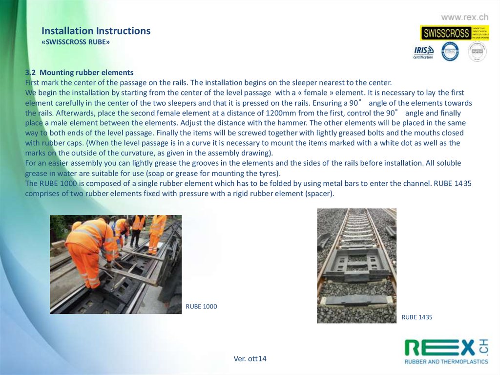
3.2 Mounting rubber elements
First mark the center of the passage on the rails. The installation begins on the sleeper nearest to the center.
We begin the installation by starting from the center of the level passage with a « female » element. It is necessary to lay the first
element carefully in the center of the two sleepers and that it is pressed on the rails. Ensuring a 90° angle of the elements towards
the rails. Afterwards, place the second female element at a distance of 1200mm from the first, control the 90° angle and finally
place a male element between the elements. Adjust the distance with the hammer. The other elements will be placed in the same
way to both ends of the level passage. Finally the items will be screwed together with lightly greased bolts and the mouths closed
with rubber caps. (When the level passage is in a curve it is necessary to mount the items marked with a white dot as well as the
marks on the outside of the curvature, as given in the assembly drawing).
For an easier assembly you can lightly grease the grooves in the elements and the sides of the rails before installation. All soluble
grease in water are suitable for use (soap or grease for mounting the tyres).
The RUBE 1000 is composed of a single rubber element which has to be folded by using metal bars to enter the channel. RUBE 1435
comprises of two rubber elements fixed with pressure with a rigid rubber element (spacer).
RUBE 1000
RUBE 1435
Ver. ott14
10.
Installation Instructions«SWISSCROSS RUBE»
«SWISSCROSS H.D.»
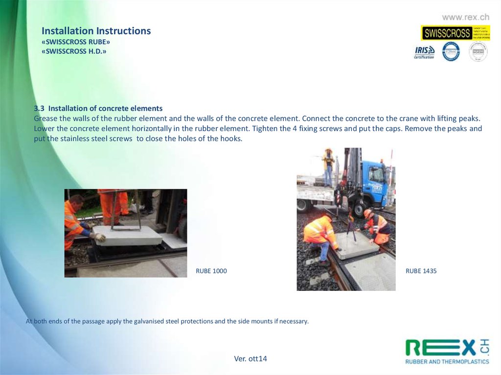
3.3 Installation of concrete elements
Grease the walls of the rubber element and the walls of the concrete element. Connect the concrete to the crane with lifting peaks.
Lower the concrete element horizontally in the rubber element. Tighten the 4 fixing screws and put the caps. Remove the peaks and
put the stainless steel screws to close the holes of the hooks.
RUBE 1000
RUBE 1435
At both ends of the passage apply the galvanised steel protections and the side mounts if necessary.
Ver. ott14
11.
Installation Instructions«SWISSCROSS RUBE»
«SWISSCROSS H.D.»
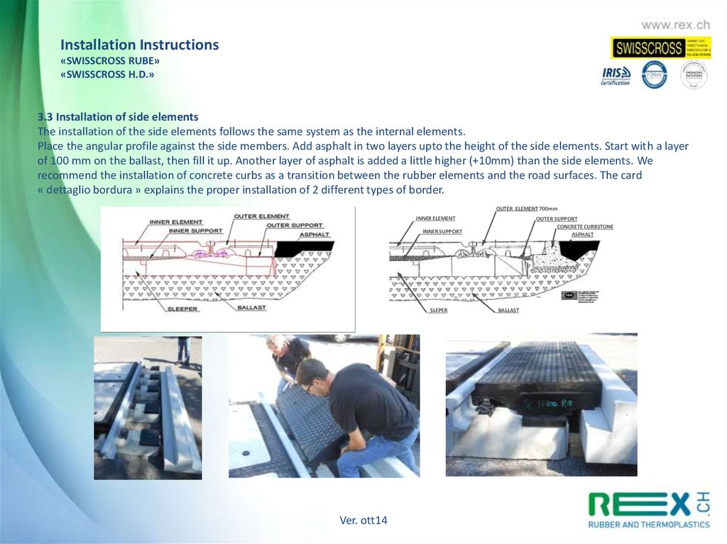
3.3 Installation of side elements
The installation of the side elements follows the same system as the internal elements.
Place the angular profile against the side members. Add asphalt in two layers upto the height of the side elements. Start with a layer
of 100 mm on the ballast, then fill it up. Another layer of asphalt is added a little higher (+10mm) than the side elements. We
recommend the installation of concrete curbs as a transition between the rubber elements and the road surfaces. The card
« dettaglio bordura » explains the proper installation of 2 different types of border.
OUTER ELEMENT 700mm
INNER ELEMENT
OUTER SUPPORT
CONCRETE CURBSTONE
ASPHALT
INNER SUPPORT
SLEPER
Ver. ott14
BALLAST
12.
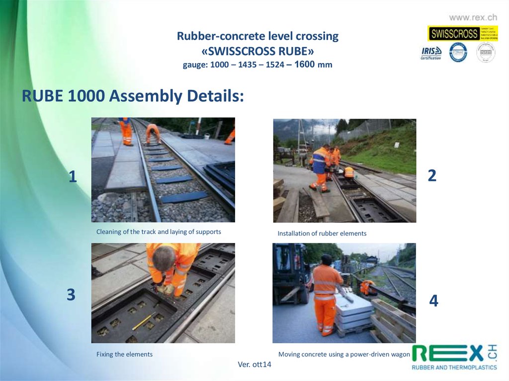
Rubber-concrete level crossing«SWISSCROSS RUBE»
gauge: 1000 – 1435 – 1524 – 1600 mm
RUBE 1000 Assembly Details:
2
1
Cleaning of the track and laying of supports
Installation of rubber elements
3
4
Fixing the elements
Moving concrete using a power-driven wagon
Ver. ott14
13.
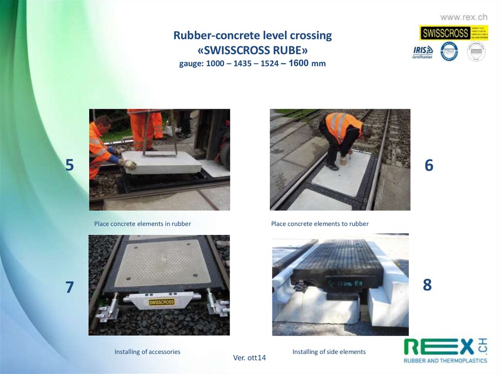
Rubber-concrete level crossing«SWISSCROSS RUBE»
gauge: 1000 – 1435 – 1524 – 1600 mm
5
6
Place concrete elements in rubber
Place concrete elements to rubber
8
7
Installing of accessories
Ver. ott14
Installing of side elements
14.
Rubber-concrete level crossing«SWISSCROSS RUBE»
gauge: 1000 – 1435 – 1524 – 1600 mm
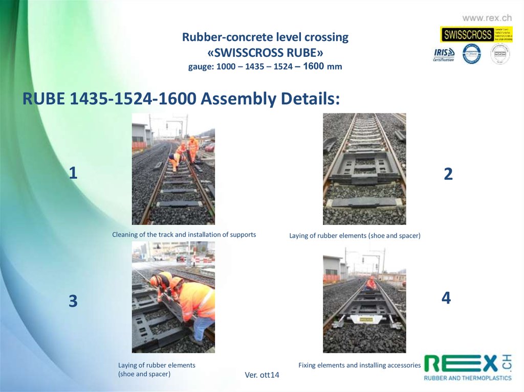
RUBE 1435-1524-1600 Assembly Details:
1
2
Cleaning of the track and installation of supports
Laying of rubber elements (shoe and spacer)
4
3
Laying of rubber elements
(shoe and spacer)
Fixing elements and installing accessories
Ver. ott14
15.
Rubber-concrete level crossing«SWISSCROSS RUBE»
gauge: 1000 – 1435 – 1524 – 1600 mm
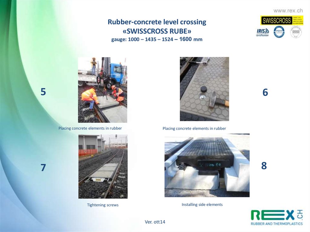
5
6
Placing concrete elements in rubber
Placing concrete elements in rubber
8
7
Installing side elements
Tightening screws
Ver. ott14
16.
Rubber-concrete level crossing«SWISSCROSS RUBE»
gauge: 1000 – 1435 – 1524 – 1600 mm
RAMS : PL Rube 1000-1435
Description of the system in which the product is inserted:
The new level passage at Swisscross RUBE allows vehicular crossing on railway lines.
It is recommended for PL medium and high road traffic.
The new Swisscross RUBE model combines the advantages of the level passage in
concrete with the advantages of the rubber passage.
Advantages:
•Better vibration and noise absorptions.
•Worn major and decrease in deformation during the passage of heavy vehicles.
•Fast and efficient assembly, disassembly for «jamming».
•Longer life.
•Better reaction in case of frost and rain.
•Better stability .
•Guaranteed electrical isolation between the two binaries.
Ver. ott14
17.
Rubber-concrete level crossing«SWISSCROSS RUBE»
gauge: 1000 – 1435 – 1524 – 1600 mm
RAMS : PL Rube 1000-1435
Description of the environnement in which the product has been introduced:
Resistant to the weather present in the railway environment.
Resistant to stresses caused by passing vehicles.
Does not disrupt railroad traffic.
Only suitable for tracks with monobloc concrete sleepers. Prescribed distance between
the sleepers: 60cm.
Class traffic: up to 700 PL/j/s (with concrete curb).
Ver. ott14
18.
Rubber-concrete level crossing«SWISSCROSS RUBE»
gauge: 1000 – 1435 – 1524 – 1600 mm
RAMS : PL Rube 1000-1435
Reliability :
The Swisscross Rube level passage is guaranteed for 5 years, provided their preventive maintenance
is done regularly and the wear parts are replaced. The guarantee is no longer valid in cases of
modifications brought about by the client without Swisscross’s consent. The warranty is valid from
the date of signing the correct installation certificate.
It is advisable to combine preventive maintenance with the « filling » of the railway track.
- PL on a regular traffic (<700 PL/j/s):
inspection every 2 years
-PL with intense traffic (700-1200 PL/j/s): annual inspection
Control mode: Remove the most sought after element. Check the condition of the rubber element,
the concrete element and the support.
The support is considered as the wearing part. It is guaranteed for 2 years. The rubber and concrete
element are guaranteed for 5 years.
The costs generated by preventive maintenance inspections are under the responsibility of the
customer.
Expired warranty or not – Swisscross maintenance is not responsible for dammages caused by a
system malfunction.
Ver. ott14
19.
Rubber-concrete level crossing«SWISSCROSS RUBE»
gauge: 1000 – 1435 – 1524 – 1600 mm
RAMS : PL Rube 1000-1435
Security
For the installation of the Swisscross level passage enforce safety provisions of the rail
yards.
The responsibility for the security relies on the client’s competence.
Ver. ott14
20.
Rubber-concrete level crossing«SWISSCROSS RUBE»
gauge: 1000 – 1435 – 1524 – 1600 mm
RAMS : PL Rube 1000-1435
Availability
Swisscross ensures the supply of wear parts in Europe within two weeks of the order.
For the supply of the concrete element or the rubber element you need to count a
delivery time of 4-6 weeks.
PL RUBE is compatible with PL HD Swisscross. The RUBE element can be temporarily
replaced by an HD Swisscross rubber element.
Ver. ott14
21.
Rubber-concrete level crossing«SWISSCROSS RUBE»
gauge: 1000 – 1435 – 1524 – 1600 mm
RAMS : PL Rube 1000-1435
Handling, packaging , transport and storage
Handling of rubber elements must be carried out by four people for the RUBE 1435
element and by two people for the RUBE 1000 element.
The movement of the concrete elements must be performed with a special lifting
equipment.
The transportation of the rubber elements does not require a special package. The
concrete elements must be properly packed to prevent breakage and slippage.
Swisscross only assumes the responsibility for transportation only upto the warehouse
(without unloading). The movements on the site are the customer’s responsibility.
Swisscross assumes no responsibility for theft of material at the warehouse or on the
site.
Ver. ott14
22.
Rubber-concrete level crossing«SWISSCROSS RUBE»
gauge: 1000 – 1435 – 1524 – 1600 mm
RAMS : PL Rube 1000-1435
Disposal of waste:
The rubber elements must be disposed of as bulky waste items. Concrete elements
must be disposed of as being inert. The material for the fixings must be disposed of as
‘‘old iron’’.
The disposal is the client’s responsibility.
Ver. ott14
23.
«SWISSCROSS RUBE WITH SIDE ELEMENT IN RUBBER-CONCRETE»PROTOTYPE 2014
The new model Swisscross RUBE combines the advantages of the
concrete crossing with the advantages of the rubber crossing, now
with a better load resistance!
•ADVANTAGES:
•Best vibration damping and noise reduction
•More Load resistance and less deformation
•Quick and rational assembling
•Better resistance and durability
•Best behavior with frosting and rain
•High stability
•Ensure electrical isolation between the two rails
Ver. ott14
24.
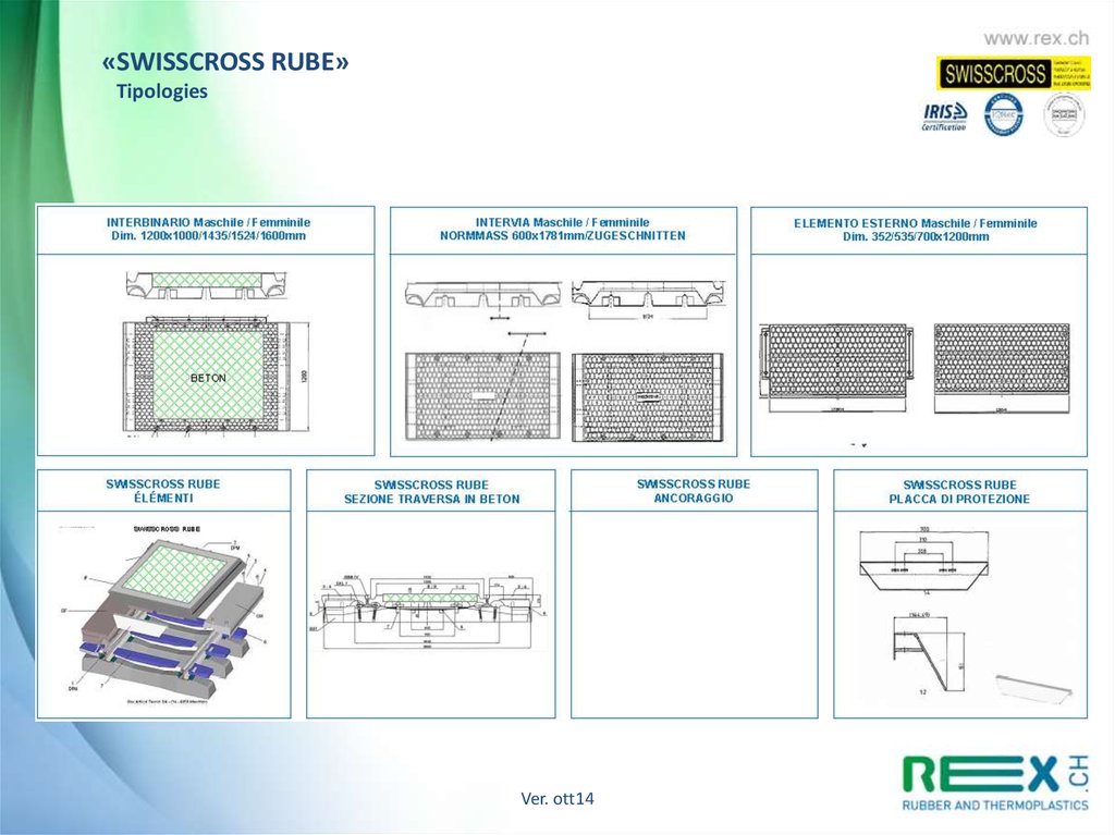
«SWISSCROSS RUBE»Tipologies
Ver. ott14
25.
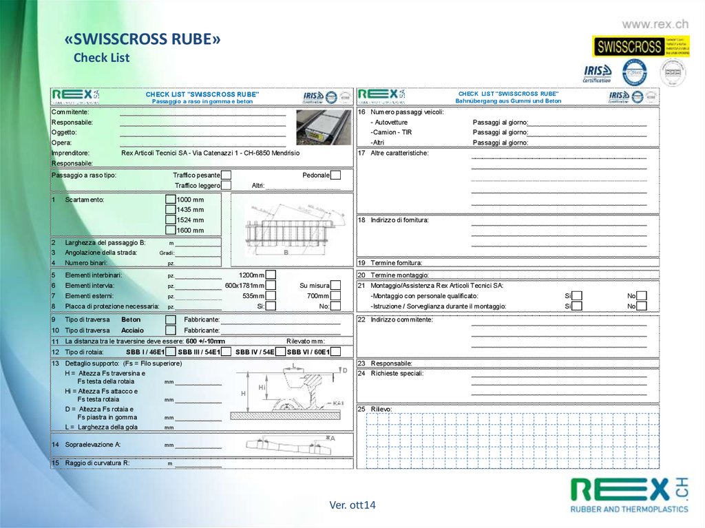
«SWISSCROSS RUBE»Check List
CHECK LIST "SWISSCROSS RUBE"
Bahnübergang aus Gummi und Beton
CHECK LIST "SWISSCROSS RUBE"
Passaggio a raso in gomma e beton
Commitente:
16 Numero passaggi veicoli:
Responsabile:
- Autovetture
Passaggi al giorno:
Oggetto:
-Camion - TIR
Passaggi al giorno:
Opera:
-Altri
Passaggi al giorno:
Imprenditore:
Rex Articoli Tecnici SA - Via Catenazzi 1 - CH-6850 Mendrisio
17 Altre caratteristiche:
Responsabile:
Passaggio a raso tipo:
Traffico pesante
Pedonale
Traffico leggero
1
Scartamento:
Altri:
1000 mm
1435 mm
1524 mm
18 Indirizzo di fornitura:
1600 mm
2
Larghezza del passaggio B:
3
Angolazione della strada:
4
Numero binari:
pz.
5
Elementi interbinari:
pz.
1200mm
6
Elementi intervia:
pz.
600x1781mm
Su misura
7
Elementi esterni:
pz.
535mm
700mm
8
Placca di protezione necessaria:
pz.
Si:
No:
9
Tipo di traversa
10 Tipo di traversa
m
B
Gradi:
19 Termine fornitura:
Beton
Fabbricante:
Acciaio
Fabbricante:
SBB I / 46E1
SBB III / 54E1
13 Dettaglio supporto: (Fs = Filo superiore)
H = Altezza Fs traversina e
Fs testa della rotaia
mm
Hi = Altezza Fs attacco e
Fs testa rotaia
mm
D = Altezza Fs rotaia e
Fs piastra in gomma
mm
L = Larghezza della gola
mm
14 Sopraelevazione A:
15 Raggio di curvatura R:
21 Montaggio/Assistenza Rex Articoli Tecnici SA:
-Montaggio con personale qualificato:
Si
No
-Istruzione / Sorveglianza durante il montaggio:
Si
No
22 Indirizzo commitente:
11 La distanza tra le traversine deve essere: 600 +/-10mm
12 Tipo di rotaia:
20 Termine montaggio:
Rilevato mm:
SBB IV / 54E
SBB VI / 60E1
L
H
D
23 Responsabile:
24 Richieste speciali:
Hi
25 Rilievo:
A
mm
m
Ver. ott14
26.
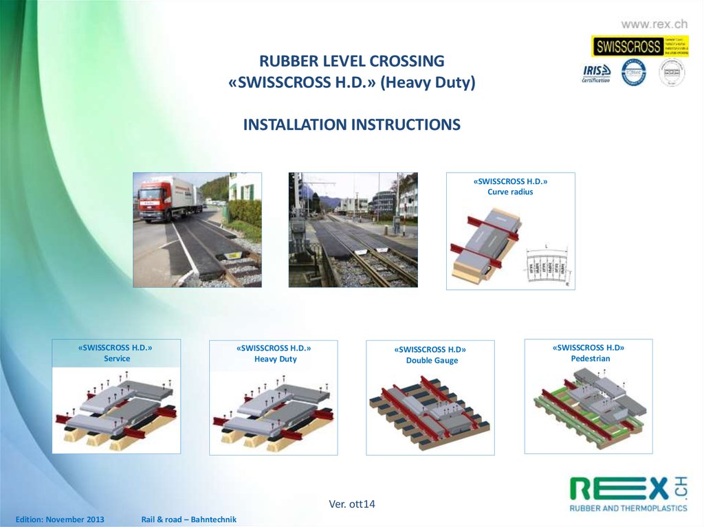
RUBBER LEVEL CROSSING«SWISSCROSS H.D.» (Heavy Duty)
INSTALLATION INSTRUCTIONS
«SWISSCROSS H.D.»
Curve radius
«SWISSCROSS H.D.»
Service
«SWISSCROSS H.D.»
Heavy Duty
«SWISSCROSS H.D»
Double Gauge
Ver. ott14
Edition: November 2013
Rail & road – Bahntechnik
«SWISSCROSS H.D»
Pedestrian
27.
Rubber Level Crossing«SWISSCROSS H.D.» (Heavy Duty)
gauge 1000, 1435 and 1524mm
INSTALLATION INSTRUCTIONS
1. APPLICATION
2. REQUIRED EQUIPMENT AND TOOLS
3. ASSEMBLY
3.1 Ground preparation
3.2 Assembly of components
3.3 Attachment of outer parts
4. MAINTENANCE
4.1 Maintenance in winter
4.2 Detaching and reassembly
Technical support and sales consultation by Rex Articoli Tecnici SA
Ver. ott14
Edition: November 2013
Rail & road – Bahntechnik
28.
Installation instructions«SWISSCROSS H.D.» gauge 1000, 1435 and 1524mm
1. APPLICATION
This assembly guide applies to the “SWISSCROSS H.D“ rubber railroad crossings.
The SWISSCROSS H.D. railroad crossings can be built into almost any common railways.
For a satisfying development and completion, we recommend completing the “SWISSCROSS Check-List“. In case there is
ambiguity, Rex will provide a technician for measuring and project drawing for free.
2. NEEDED EQUIPMENT AND TOOLS (Suggested)
- Crane for lifting the parts (for example a mini-digger)
- Assembly hook, eyebolts for lifting the components
- Grease (for example as used in tyre assembling)
- Shaker to make the gravel dense and a shovel
- Sledgehammer, hammer
- Protection grade for the threads (for example machine grease)
- Percussion drill
- Ring wrench 24 mm
3. ASSEMBLY
3.1 Ground preparation
The location of the crossing is marked, in consideration that the rubber parts need to overlap the railway on the sides by 50 cm (adjust to local
standards). At the same time, other required measurements should be made. Sometimes, the railroad crossings are arranged diagonally. The
clearance must be designed like this (as a guide):
If the crossing angle (see fig. 1) is more than 80°, nothing needs to be considered. At an angle of 70-80°, it would be wise to cover one more, at
an angle less than 70°, two more sleepers.
Figure 1
Ver. ott14
Edition: November 2013
Rail & road – Bahntechnik
29.
Installation instructions«SWISSCROSS H.D.» gauge 1000, 1435 and 1524mm
Around the crossing, 70 cm of the old surface outside of the rails has to be removed up to the end of the sleepers. If the traffic cannot be stopped
completely, the assembly will have to be done in two or more steps. The sleepers might have to be strengthened with a tamping machine. The
space between the sleepers should be 600 +/- 10 mm counting from the middle of the sleeper, but 4x600 mm should be 2,400 mm +/- 30 mm. If
the sleepers have to be strengthened, it is recommended to do so before the assembly. If there is a danger of water being collected in or under
the area of the crossing, an according drain will have to be placed beforehand. The rubber base plates are placed upon the sleepers between the
rails, fig. 2.
If wooden sleepers are used, the rubber plates have to be attached to them with screws. Steel nails are used to attach the base plates to the
Azobe-sleepers. Iron nails (100 mm) can be used with the plates instead of screws. However, using screws is recommended. When the rubber
plates are placed on the sleepers outside of the rails, the plates should be attached in such a way that they close off in a straight line with the
edges of the sleepers. Rail gravel has to be raised carefully and tamped, so that it‘s even with the upper edge of the base plates. It is advisable to
check the level with a yardstick, so no single gravel stones jut out past the height of the seating. (In that case, the components could not be
assembled cleanly between the rails.)
Figure 2
3.2 Assembly of rubber components
First mark the center of the way on the rails. The assembly starts from the nearest sleeper (center). Place the anchor plate (if used) on that center
sleeper. Make sure the outer parts are assembled correctly with different lengths of railroad crossings. (For short crossings of for example 4.8 or
6.0m, the anchor plate can be at the end of the crossing, and the assembly can start from there.) Check the assembly blueprint. The assembly
starts from the center of the crossing with a “female” component. The inner component is lifted at the center with an assembly hook. Thus, the
element will bend slightly in the middle for easier assembly. The first inner component has to be placed very carefully in the center between two
sleepers, with its ends adjoining the rails. Make sure the first element is placed at an angle of 90° to the tracks. Then place the second female
element at a distance of 600 mm to the first one, check the 90° angle and then place the male element between those two.
Ver. ott14
30.
«SWISSCROSS H.D.»Assembly guide gauge 1000, 1435 und 1524mm
The other elements are assembled accordingly until the end of the crossing. The components are carefully butted against each other with a
sledgehammer. Eventually, the parts are assembled with lightly greased screws and the indentations covered with a lid. (If the crossing is at a
bend, all the white tagged ends of the “bend-elements” have to be assembled in such a way that the white markings point towards the outside of
the bend, as it is sated in the guide.) To ease the assembly, the channelings in the components and the edges on the rail sides can be greased
before assembly. Every grease that dissolves well in water is suitable, such as tyre-assembly grease or soap. At the end, assemble the linkagesafety plates at the end of the crossing.
The installing of the Outer Elements starts once again in the centre and works towards the edges. The Outer Elements are lifted with the same
assembly hook. The components are connected in the same way as the inner elements. Heed the correct assembly as shown on the drawing. At
the end, assemble the safety plates at the edges of the crossing.
3.3 Attachment of the outer parts
Tarmac is applied in 2 layers up to the height of the Outer Elements. First, about 100 mm of tarmac are spread over the gravel, then it is tamped.
Another layer of tarmac is applied a little higher (+10 mm) than the Outer Elements on top of that. We suggest the assembly of concrete curb
stones as transition from the rubber elements and the pavement. During the maintenance work on the rails, the pavement will not be damaged.
OUTER ELEMENT 700mm
OUTER SUPPORT
INNER ELEMENT
CONCRETE CURBSTONE
ASPHALT
INNER SUPPORT
535mm
SLEPER
BALLAST
4. MAINTENANCE
4.1 Maintenance in winter
In winter, salt and grit is used to make the streets safe. Salt and grit can applied to the railroad crossings, but it is better to avoid it. Glaze forming
on the rubber surface will be removed by the traffic (because of the elasticity of the rubber, the ice will be removed by car wheels). Bonded snow
should be removed from the crossings very carefully, so the profiled surface of the rubber parts will not be destroyed. It is recommended to only
sweep snow and ice from the railroad crossings.
Ver. ott14
31.
Installation instructions«SWISSCROSS H.D.» gauge 1000, 1435 and 1524mm
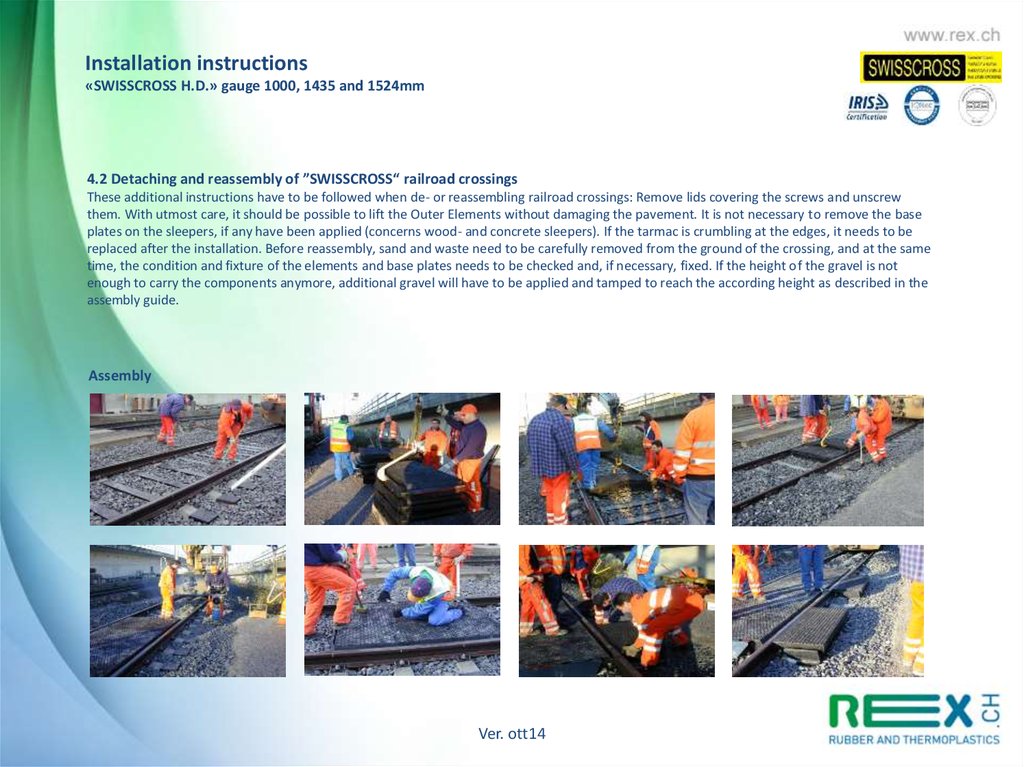
4.2 Detaching and reassembly of ”SWISSCROSS“ railroad crossings
These additional instructions have to be followed when de- or reassembling railroad crossings: Remove lids covering the screws and unscrew
them. With utmost care, it should be possible to lift the Outer Elements without damaging the pavement. It is not necessary to remove the base
plates on the sleepers, if any have been applied (concerns wood- and concrete sleepers). If the tarmac is crumbling at the edges, it needs to be
replaced after the installation. Before reassembly, sand and waste need to be carefully removed from the ground of the crossing, and at the same
time, the condition and fixture of the elements and base plates needs to be checked and, if necessary, fixed. If the height of the gravel is not
enough to carry the components anymore, additional gravel will have to be applied and tamped to reach the according height as described in the
assembly guide.
Assembly
Ver. ott14
32.
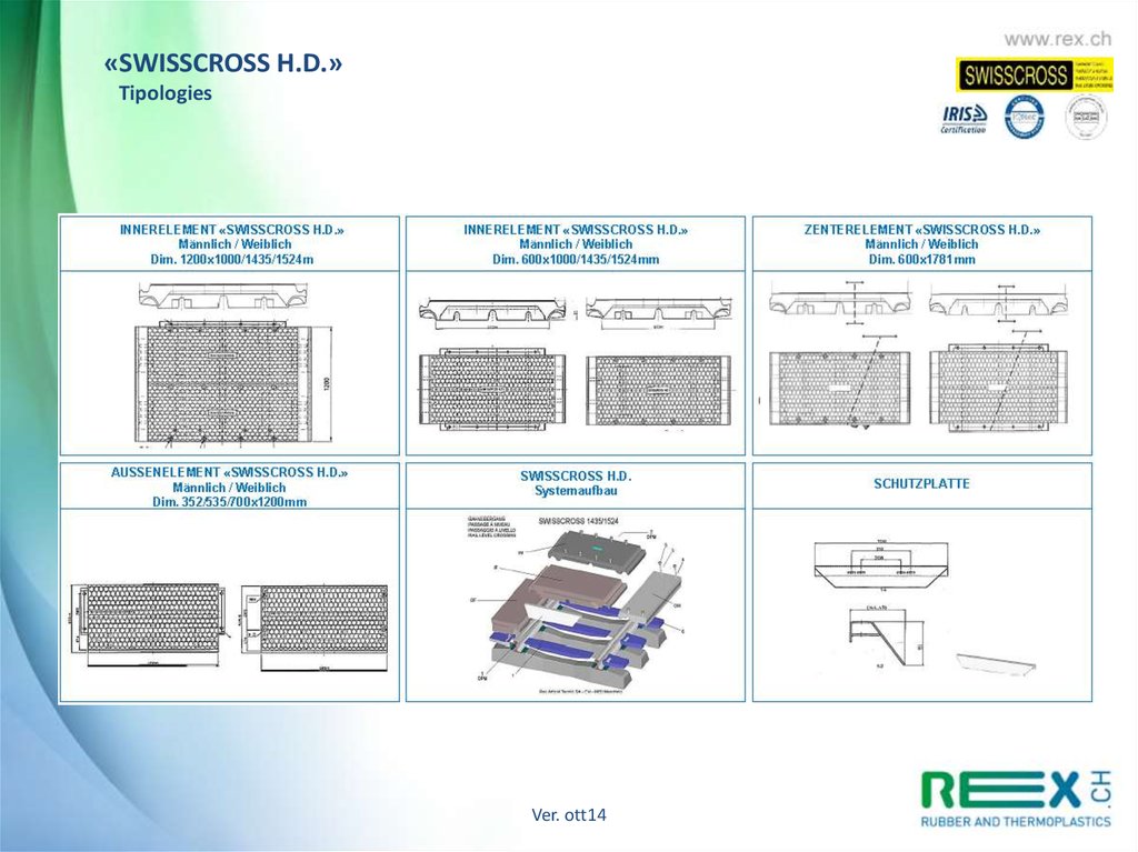
«SWISSCROSS H.D.»Tipologies
Ver. ott14
33.
«SWISSCROSS H.D.»Check List
CHECK LIST "SWISSCROSS H.D."
Bahnübergang aus Gummi
CHECK LIST "SWISSCROSS H.D."
Bahnübergang aus Gummi
Bauherr:
16 Fahrzeugüberquerungen:
Zuständig:
- Personenwagen
Anzahl pro Tag:
Objekt:
-Lastwagen - TIR
Anzahl pro Tag:
Bauvorhaben:
-Andere
Anzahl pro Tag:
Auftragnehmer:
Rex Articoli Tecnici SA - Via Catenazzi 1 - CH-6850 Mendrisio
17 Andere Besonderheiten:
Zuständig:
Bahnübergang Typ:
Schwerverkehr
Leichter Verkehr
1
Spurweite:
Fussgänger
Andere
1000 mm
1435 mm
1524 mm
18 Lieferadresse:
3-Schienengleis
2
Breite des Bahnüberganges B:
3
Strassenwinkel:
4
Anzahl der Gleise:
stk.
5
Innerelemente im Gleis:
stk.
1200mm
600mm
6
Zenter-Elemente
stk.
600x1781mm
Zugeschnitten
7
Aussenelemente:
stk.
535mm
700mm
8
Kupplungsschutzplatten notwendig:
Nein
stk.
9
Schwellentyp:
m
B
Grad
19 Lieferdatum:
Ja
-Montage mit qualifiziertem Personal
Ja
Nein
-Einschulung / Montageaufsicht
Ja
Nein
22 Anschrift Bauherr:
Hersteller:
11 Befestigung:
Hersteller:
12 Schwellenabstand soll sein: 600 +/-10mm
13 Vermessung Bahnschiene: (Ok = Oberkante)
H = Höhe Ok Schwelle und
Ok Schienenkopf
mm
Hi = Höhe Ok Schienenbefestigung
und OK Schiene
mm
D = Höhe Ok Schienenkopf und
Ok. Gummiplatte
mm
L = Spurrillenbreite
mm
15 Kurvenradius R:
21 Montage/Montageaufsicht durch Rex Articoli Tecnici SA:
Hersteller:
10 Schienentyp:
14 Überhöhung A:
20 Montagetermin:
Bestehend mm:
L
D
23 Zuständig:
24 Spezielle Ausführungen:
Hi
H
25 Zeichnung des Bahnüberganges:
A
mm
m
Ver. ott14
34.
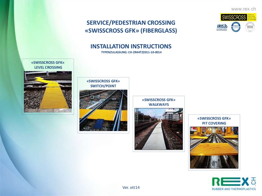
SERVICE/PEDESTRIAN CROSSING«SWISSCROSS GFK» (FIBERGLASS)
INSTALLATION INSTRUCTIONS
TYPENZULASSUNG: CH-ZR44TZ2011-10-0014
«SWISSCROSS GFK»
LEVEL CROSSING
«SWISSCROSS GFK»
SWITCH/POINT
«SWISSCROSS GFK»
WALKWAYS
«SWISSCROSS GFK»
PIT COVERING
Ver. ott14
35.
Service/pedestrian crossing«SWISSCROSS GFK»
INSTALLATION INSTRUCTIONS
1. FIELD OF APPLICATION
2. TOOLS AND MATERIALS REQUIRED FOR INSTALLATION
3. INSTALLATION
3.1 Setup
3.2 Installation
4. MAINTENANCE
4.1 Disassembly and reassembly
4.2 Maintenance
5. ITEM DETAILS
Technical and sales reference information from Rex Articoli Tecnici SA
Ver. ott14
36.
Installation instructions«SWISSCROSS GFK»
1.
FIELD OF APPLICATION
These instructions apply to all SWISSCROSS GFK models of service passageways, footpaths, walkways, escape routes and rescue platforms,
both outdoor and in tunnels. The exclusive laying system helps the integration with any type of track. To ensure the correct implementation
design, we recommend the use of the check-list supplied with the offer. A free technical inspection on site is available from Rex Articoli
Tecnici SA, upon customer request.
2.
TOOLS AND MATERIALS REQUIRED FOR INSTALLATION (see enclosed list)
Laying surface
Tape meter, folding ruler, chalk, pencil
Level, straightedge
Hammer
Percussion drill with bits
Battery-powered screwer with inserts
Jigsaw, battery-powered
Circular saw with steel blade
Grinder, battery-powered with steel disc
Screwdriver kit, both flat blade and Philips
Allen wrench kit
Cricket wrench kit with accessories
Clamps
Square ruler
3 INSTALLATION
3.1 Setup
The assembly of SWISSCROSS GFK passageway does not require highly qualified technicians. However, we recommend an initial training and
overview by a Rex specialist during the first installation. Services provided by Rex Articoli Tecnici SA include: onsite inspection, survey and
evaluation, offer design and preparation. Supply and installation performed by qualified specialist are available upon request.
The location of the passageway should be marked according to the laying surface (or to local specifications). All other dimensions should be
adjusted accordingly. In the level crossing area, the existing framework should be removed, if needed.
If crossing cannot be obstructed, the installation can be divided in two separate sections to be agreed with the clerks of works.
Ver. ott14
37.
Installation instructions«SWISSCROSS GFK»
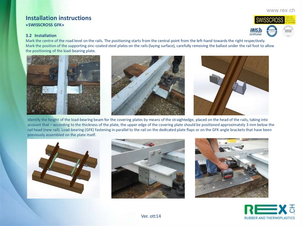
3.2 Installation
Mark the centre of the road level on the rails. The positioning starts from the central point from the left-hand towards the right respectively.
Mark the position of the supporting zinc-coated steel plates on the rails (laying surface), carefully removing the ballast under the rail foot to allow
the positioning of the load-bearing plate.
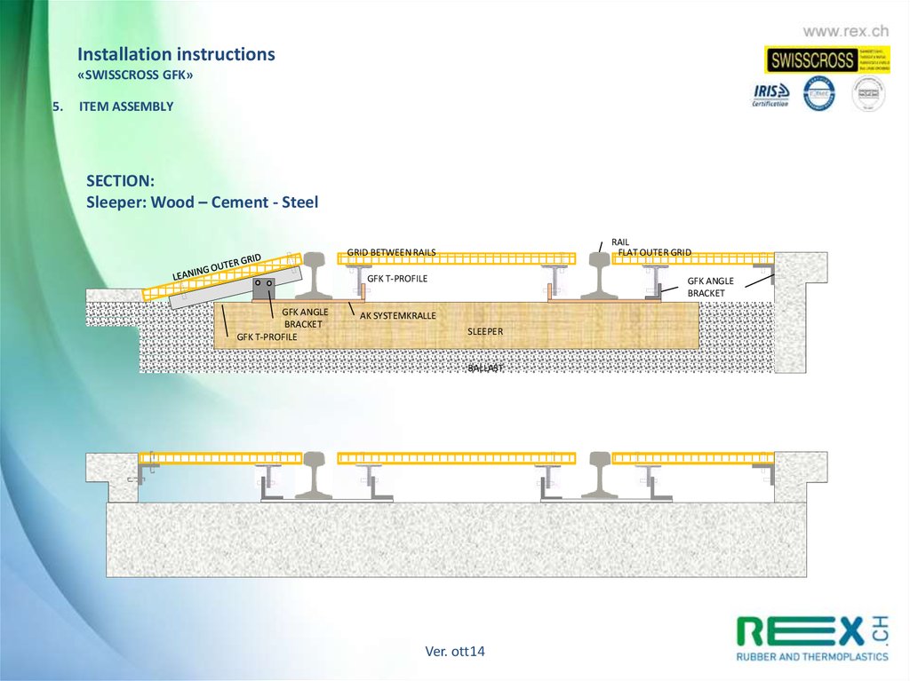
Identify the height of the load-bearing beam for the covering plates by means of the straightedge, placed on the head of the rails, taking into
account that – according to the thickness of the plate, the upper edge of the covering plate should be positioned approximately 3 mm below the
rail head (new rail). Load-bearing (GFK) fastening in parallel to the rail on the dedicated plate flaps or on the GFK angle brackets that have been
previously assembled on the plate itself.
Ver. ott14
38.
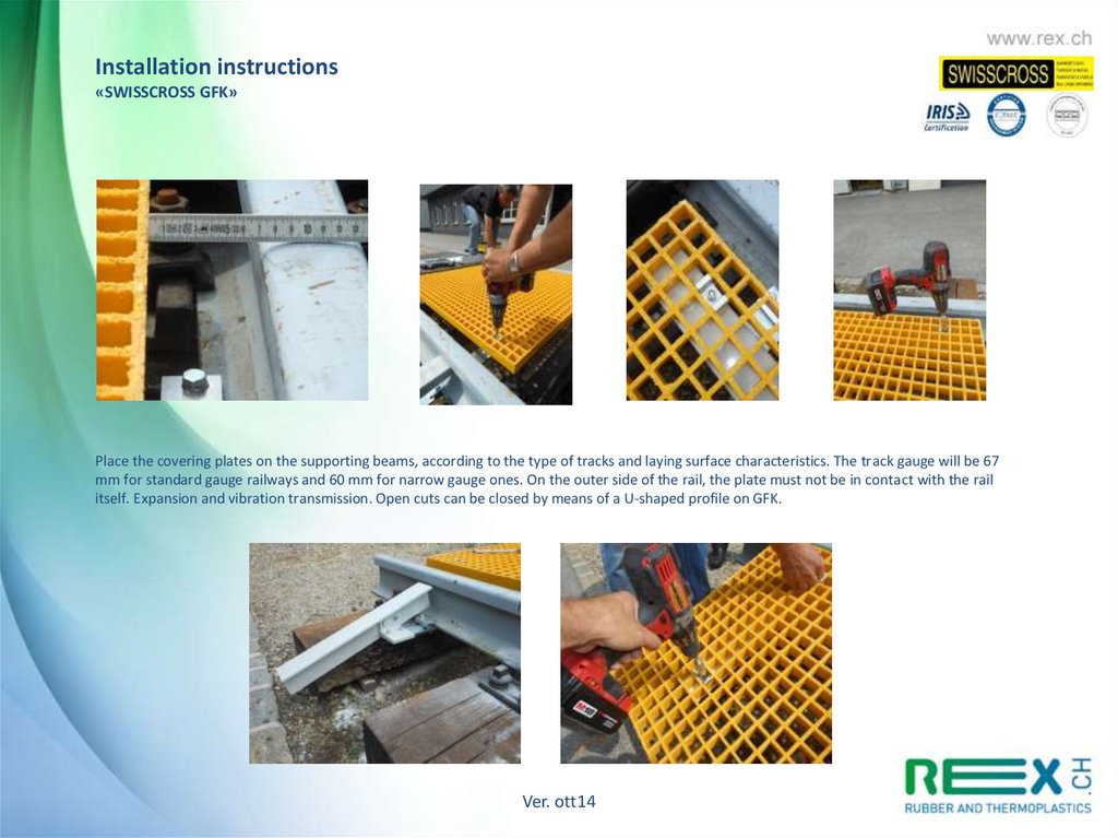
Installation instructions«SWISSCROSS GFK»
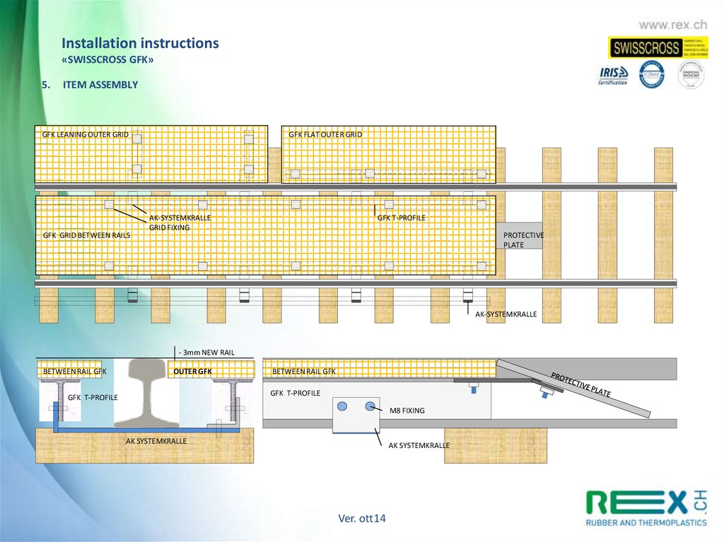
Place the covering plates on the supporting beams, according to the type of tracks and laying surface characteristics. The track gauge will be 67
mm for standard gauge railways and 60 mm for narrow gauge ones. On the outer side of the rail, the plate must not be in contact with the rail
itself. Expansion and vibration transmission. Open cuts can be closed by means of a U-shaped profile on GFK.
Ver. ott14
39.
Installation instructions«SWISSCROSS GFK»
Covering plate assembly with special fixing elements, usually about 4 fixing/sqm, or according to specific requirements.
To complete, install the protective plates between the rails by means of hanging hooks at the passage ends.
4. MAINTENANCE
4.1 Disassembly and reassembly of the service passageway
SWISSCROSS GFK passageways can be easily and quickly disassembled for track maintenance needs. However, in order to avoid issues and drilling
of new holes to attach the items, we suggest to follow the indications below, especially for rail replacement. Prepare an accurate survey of
the framework before removal, to enable the reassembly of all elements as previously installed. If needed, a Rex specialist is available for
onsite inspection and assistance.
4.2 Maintenance
Due to the quality of the construction materials, SWISSCROSS GFK passageways do not require any particular maintenance.
Upon customer request, Rex provides a project-specific survey and maintenance manual.
Ver. ott14
40.
Installation instructions«SWISSCROSS GFK»
5.
ITEM ASSEMBLY
SECTION:
Sleeper: Wood – Cement - Steel
RAIL
FLAT OUTER GRID
GRID BETWEEN RAILS
GFK T-PROFILE
GFK ANGLE
BRACKET
GFK T-PROFILE
GFK ANGLE
BRACKET
AK SYSTEMKRALLE
SLEEPER
BALLAST
Ver. ott14
41.
Installation instructions«SWISSCROSS GFK»
5.
ITEM ASSEMBLY
GFK LEANING OUTER GRID
GFK GRID BETWEEN RAILS
GFK FLAT OUTER GRID
AK-SYSTEMKRALLE
GRID FIXING
GFK T-PROFILE
PROTECTIVE
PLATE
AK-SYSTEMKRALLE
- 3mm NEW RAIL
BETWEEN RAIL GFK
OUTER GFK
BETWEEN RAIL GFK
GFK T-PROFILE
GFK T-PROFILE
M8 FIXING
AK SYSTEMKRALLE
AK SYSTEMKRALLE
Ver. ott14
42.
«SWISSCROSS GFK»Check List
CHECK LIST "SWISSCROSS GFK"
CHECK LIST "SWISSCROSS GFK"
Passaggio di servizio
Passaggio di servizio
Commitente:
14 Sopraelevazione A:
Responsabile:
mm
Oggetto:
15 Raggio di curvatura:
Opera:
16 Infrastruttura:
Imprenditore:
Rex Articoli Tecnici SA - Via Catenazzi 1 - CH-6850 Mendrisio
m
Ballast
Responsabile:
Andere:
17 Altre catatteristiche:
Passaggio di servizio tipo:
Schotterlos:
Grigliato:
Altezza 38mm
Griglia a maglia chiusa:
Colore: Giallo
Altezza 42mm
Altro:
1
Senza Ballast
Altro:
Colore: Griggio
Altezza mm:
Scartamento A:
Colore:
1000 mm
18 Indirizzo di fornitura:
1435 mm
A
1524 mm
1600 mm
Altro mm:
2
Larghezza del passaggio B:
3
Numero dei binari:
pz.
20 Termine di montaggio:
4
Interbinario:
pz.
21 Montaggio/Assistenza Rex Articoli Tecnici SA:
5
Intervia:
pz.
6
Elemento esterno:
pz.
7
Elemento tipo:
m
19 Termine di fornitura:
B
Orizzontali
Inclinati
-Montaggio con personale qualificato:
Si:
No:
-Istruzione / Sorveglianza durante il montaggio:
Si:
No.
22 Indirizzo commitente:
7a Elemento tipo:
8
Piastra di protezione per ganci pendenti:
9
Traversina tipo:
Si
No
pz.
Fabbricante:
10 Rotaia tipo:
Fabbricante:
23 Responsabile:
11 Attacco rotaia:
Fabbricante:
24 Esecuzioni speciali:
12 La distanza tra le traversine deve essere: 600 +/-10mm
13 Rilievo binario esistente: (Fs = Filo superiore)
H = Altezza Fs traversina e
Fs Testa della rotaia
mm
Hi = Altezza Fs attacco e
Fs testa rotaia
mm
D = AltezzaFs rotaia e
Fs Grigliato
mm
L = Larghezza gola
mm
Rilevato mm:
L
D
25 Rilievo.
Hi
H
Ver. ott14
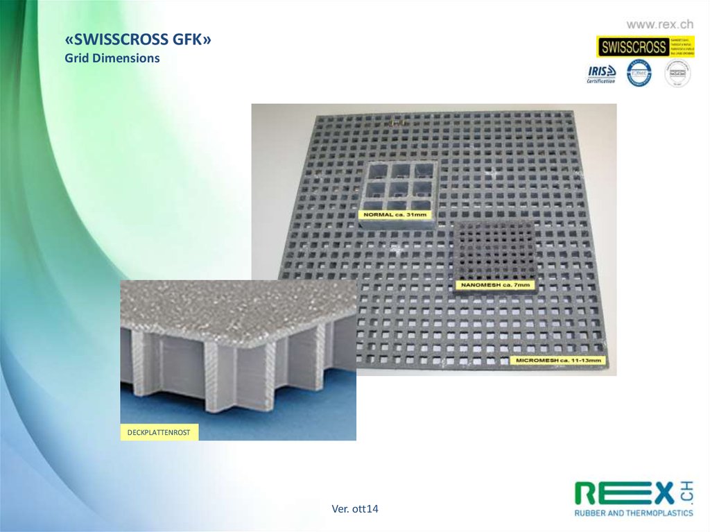
43.
«SWISSCROSS GFK»Grid Dimensions
DECKPLATTENROST
Ver. ott14
44.
CustumerInnovation
Care
Quality
Sustainability
Ver. ott14
45.
OUR SALES TEAMSALES OFFICE
CUSTOMER SERVICE
Carlo Lorandi
Karin Pitton
Susanna Celoria
SALES SWITZERLAND
RAILWAY SWISSCROSS
Claudio Rossi
Marcello Gisler
Guido Hübner
SALES GERMANY
SWISSSTOP
Thomas Pfaff
Jens Schulte
Christian Heule
www.rex.ch sales@rex.ch
END
Ver. ott14