


 electronics
Similar presentations:

")

 Wireless Audio - Soundbar ’2017 SAMSUNG ELECTRONICS CO.,LTD. VD R&D GROUP")


Training Maunal SA9900
1.
2004 SERVICE TRAINING MANUALSA9900
TRAINING MANUAL
PAGE 1
2.
2004 SERVICE TRAINING MANUALCONTENTS
1. GENERAL INFORMATION
2. BF B/D
3. Service Issue & Tips
4. Trouble Shooting
PAGE 2
3.
2004 SERVICE TRAINING MANUAL1. GENERAL INFORMATION
# Technical Specifications
1. Fine Digital Beamforming System
2. All Digital Signal Processing
- Mid signal processing ASIC – MGA015
- Color Doppler Processing ASIC – MGA016
- Multi Beam ability Beamforming ASIC - MCB014
- TX Pulser ASIC – MFC019
3. 512 channel system with synthetic
4. Cine memory : 256 Frames
5. Loop memory : 2048 Lines
6. Multi Languages-English, German, Spanish, Italian, French
7. Edge Enhancement : 10 steps (0 ~ 9)
8. Dynamic Range control : 50dB ~ 110 dB, step 1 dB
PAGE 3
4.
2004 SERVICE TRAINING MANUAL1. GENERAL INFORMATION
# PROBE LIST
1. Curved Array : 99C3-7IM, 99C2-5EL, 99EC4-9ES, 99EC4-9/10ED, 99C4-9/10ED,
99C2-5ET
2. Linear Array : 99L5-12IM, 99L4-7EV, 99L5-9ER
3. Single Element Pencil : 2.0 CW, 4.0 CW
4. Intra Operative : LI5-9EV, CL4-8EV
5. Phased Array : 99P2-3AC, 99P2-5AC, 99P3-7AC
6. TEE : MPT4-7*
7. Volume : VAW3-5, VDW5-8B, VAW4-7, VNA 6-12
* MPT4-7 is not supplied.
PAGE 4
5.
2004 SERVICE TRAINING MANUAL1. GENERAL INFORMATION
# Ultrasound workstation
1. Pentium III 700MHz
2. Hard drive: 80GBytes
3. RAM size: max.512MBytes
4. Windows 2000 Professional
5. 1.3 GBytes magneto-optical disc drive
6. CD-RW
PAGE 5
6.
2004 SERVICE TRAINING MANUALPAGE 6
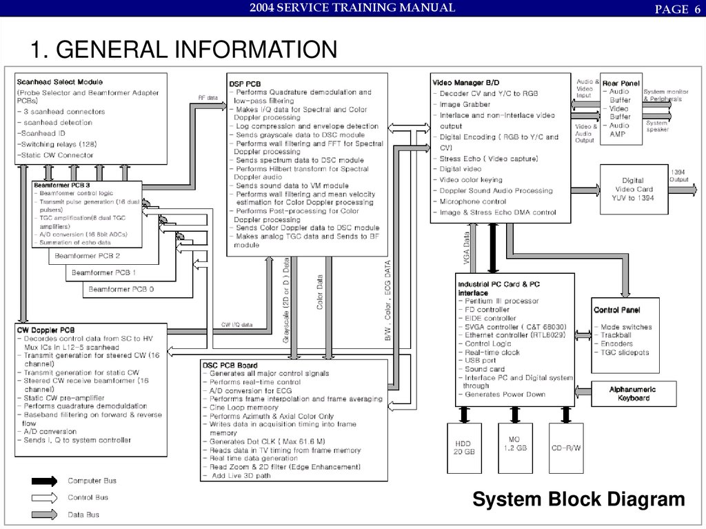
1. GENERAL INFORMATION
System Block Diagram
7.
2004 SERVICE TRAINING MANUALBeamforming Board
(BF B/D)
PAGE 7
8.
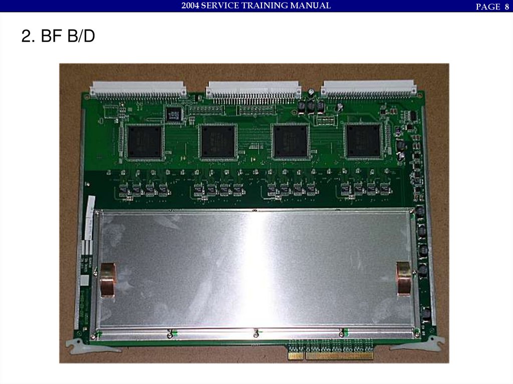
2004 SERVICE TRAINING MANUAL2. BF B/D
PAGE 8
9.
2004 SERVICE TRAINING MANUAL2. BF B/D
# Board Specification
–
48 TX PULSER/Board
–
16 LIMITER/Board
–
16 TGC AMP/Board
–
16 A/D Converter/Board
–
Synthetic Aperture support
–
Trapezoidal Imaging support
–
RX Dynamic Aperture function (Max. 64step)
–
RX Apodization function (different curve support is available per Mode)
–
Board version include in Board.
–
Each BFIC function control is available
–
Max. 4 of Multi-line receiving support
PAGE 9
10.
2004 SERVICE TRAINING MANUALPAGE 10
2. BF B/D
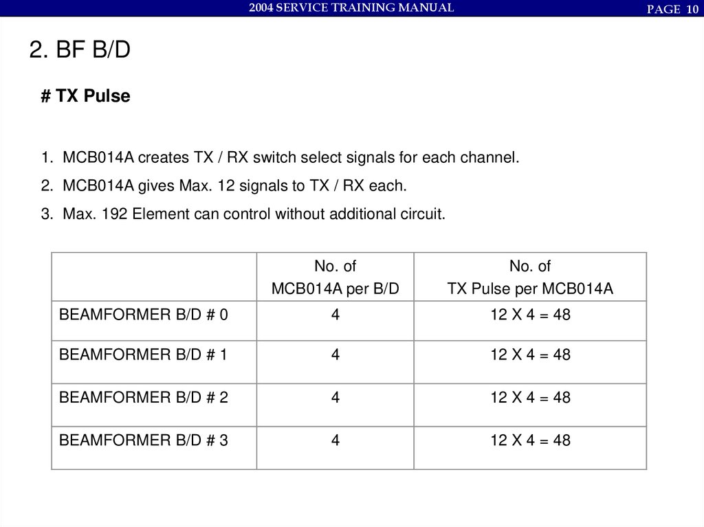
# TX Pulse
1. MCB014A creates TX / RX switch select signals for each channel.
2. MCB014A gives Max. 12 signals to TX / RX each.
3. Max. 192 Element can control without additional circuit.
No. of
MCB014A per B/D
No. of
TX Pulse per MCB014A
BEAMFORMER B/D # 0
4
12 X 4 = 48
BEAMFORMER B/D # 1
4
12 X 4 = 48
BEAMFORMER B/D # 2
4
12 X 4 = 48
BEAMFORMER B/D # 3
4
12 X 4 = 48
11.
2004 SERVICE TRAINING MANUALPAGE 11
2. BF B/D
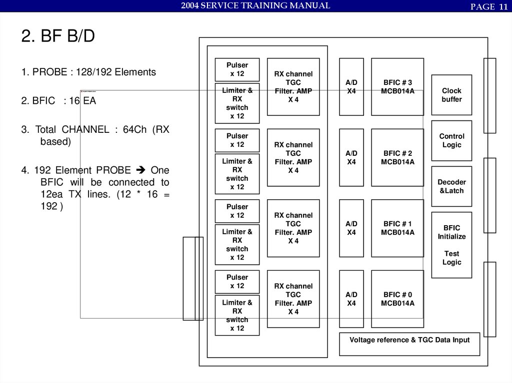
1. PROBE : 128/192 Elements
2. BFIC : 16 EA
3. Total CHANNEL : 64Ch (RX
based)
4. 192 Element PROBE One
BFIC will be connected to
12ea TX lines. (12 * 16 =
192 )
Pulser
x 12
Limiter &
RX
switch
x 12
Pulser
x 12
Limiter &
RX
switch
x 12
Pulser
x 12
Limiter &
RX
switch
x 12
Pulser
x 12
Limiter &
RX
switch
x 12
RX channel
TGC
Filter. AMP
X4
RX channel
TGC
Filter. AMP
X4
A/D
X4
BFIC # 3
MCB014A
Clock
buffer
Control
Logic
A/D
X4
BFIC # 2
MCB014A
Decoder
&Latch
RX channel
TGC
Filter. AMP
X4
A/D
X4
BFIC # 1
MCB014A
BFIC
Initialize
Test
Logic
RX channel
TGC
Filter. AMP
X4
A/D
X4
BFIC # 0
MCB014A
Voltage reference & TGC Data Input
12.
2004 SERVICE TRAINING MANUALPAGE 12
2. BF B/D
# Connect between BFIC and 128ea Elements
#0~3
#64~67
#128~131
#192
Element
BFIC #0
128 Probe BFIC 16 Chip * 8ea = 128 elements
192 Probe BFIC 16 Chip * 12ea = 192 elements
Micro Processor
13.
2004 SERVICE TRAINING MANUAL2. BF B/D
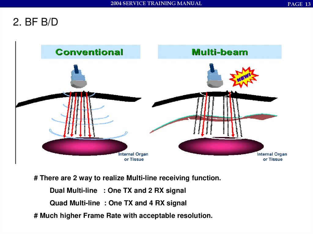
# There are 2 way to realize Multi-line receiving function.
Dual Multi-line : One TX and 2 RX signal
Quad Multi-line : One TX and 4 RX signal
# Much higher Frame Rate with acceptable resolution.
PAGE 13
14.
2004 SERVICE TRAINING MANUALPAGE 14
2. BF B/D
Tx2
Rx1
Tx4
Tx6
Rx3
Rx3
Rx3'
Tx4
Tx6
Rx1 Rx2 Rx3
Rx5
Rx5
Rx1
Tx2
Rx5'
Rx7'
Tx6
Tx6
Rx1 Rx2 Rx4 Rx5
Rx3 Rx4 Rx5
Rx7
Tx3
Rx5
Rx4 Rx5 Rx7 Rx8
Rx6 Rx7
Rx1 Rx2 Rx3’ Rx4 Rx5’ Rx6 Rx7’
# There are 2 way to realize Multi-line receiving function.
Dual Multi-line : One TX and 2 RX signal
Quad Multi-line : One TX and 4 RX signal
# Much higher Frame Rate with acceptable resolution.
Rx7 Rx8 Rx10 Rx11
Rx1 Rx2 Rx4’ Rx5’ Rx7’ Rx8’ Rx10’
15.
2004 SERVICE TRAINING MANUALPAGE 15
3. Service Issues & Tips
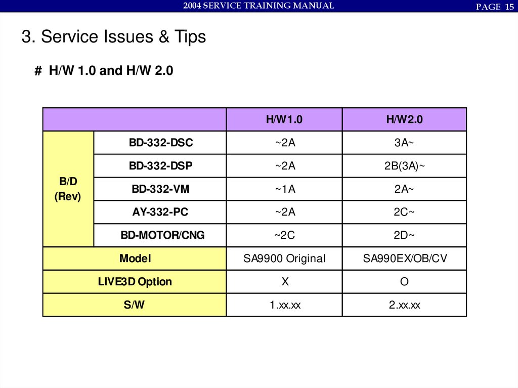
# H/W 1.0 and H/W 2.0
B/D
(Rev)
H/W1.0
H/W2.0
BD-332-DSC
~2A
3A~
BD-332-DSP
~2A
2B(3A)~
BD-332-VM
~1A
2A~
AY-332-PC
~2A
2C~
BD-MOTOR/CNG
~2C
2D~
Model
SA9900 Original
SA990EX/OB/CV
LIVE3D Option
X
O
S/W
1.xx.xx
2.xx.xx
16.
2004 SERVICE TRAINING MANUAL3. Service Issues & Tips
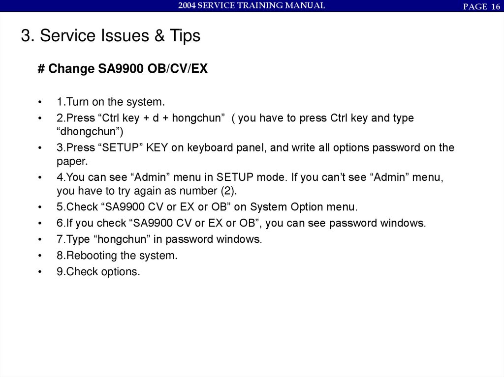
# Change SA9900 OB/CV/EX
1.Turn on the system.
2.Press “Ctrl key + d + hongchun” ( you have to press Ctrl key and type
“dhongchun”)
3.Press “SETUP” KEY on keyboard panel, and write all options password on the
paper.
4.You can see “Admin” menu in SETUP mode. If you can’t see “Admin” menu,
you have to try again as number (2).
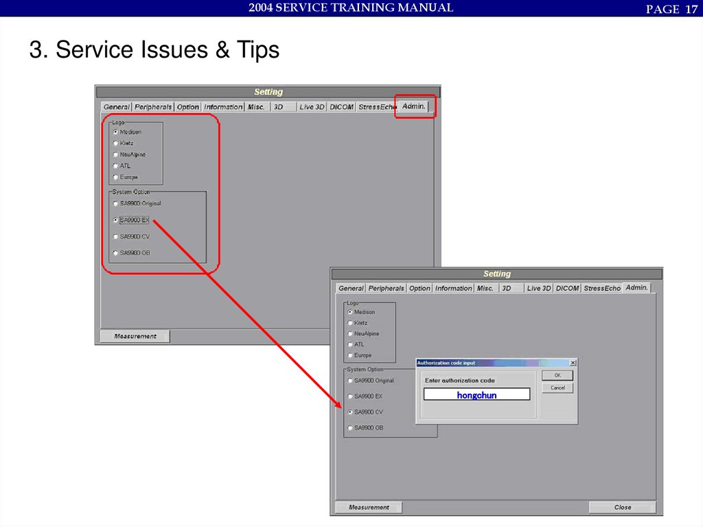
5.Check “SA9900 CV or EX or OB” on System Option menu.
6.If you check “SA9900 CV or EX or OB”, you can see password windows.
7.Type “hongchun” in password windows.
8.Rebooting the system.
9.Check options.
PAGE 16
17.
2004 SERVICE TRAINING MANUALPAGE 17
3. Service Issues & Tips
hongchun
18.
2004 SERVICE TRAINING MANUALPAGE 18
3. Service Issues & Tips
M odel
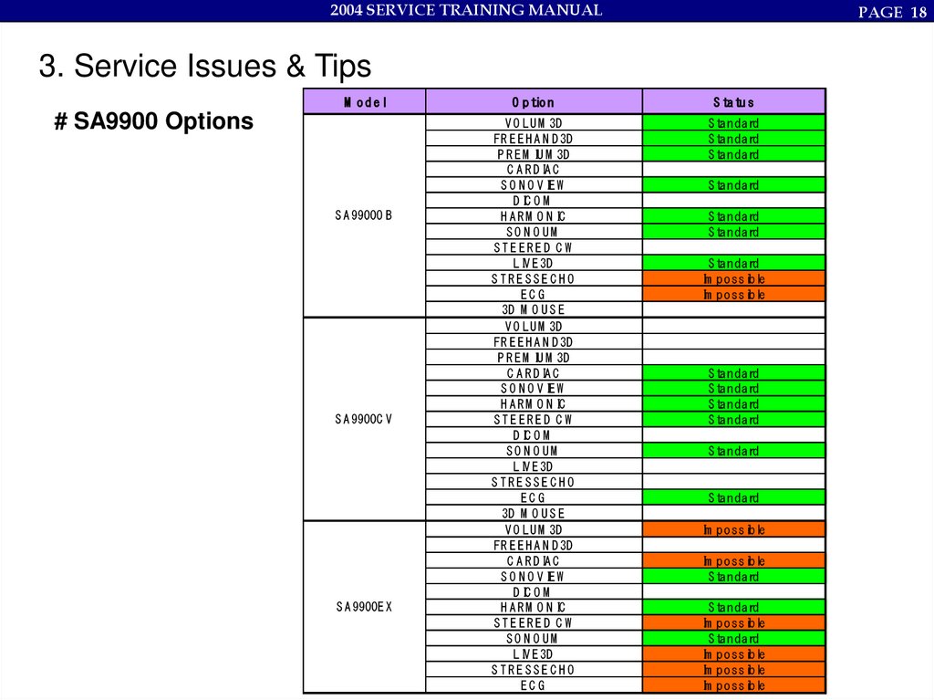
# SA9900 Options
S A 9900O B
S A 9900C V
S A 9900E X
O p tio n
S ta tu s
V O LU M 3D
FR E E H A N D 3D
P R E M IU M 3D
C A R D IA C
S O N O V IE W
D IC O M
H A R M O N IC
SO N O UM
STEERED C W
LIV E 3D
STRESSEC HO
EC G
3D M O U S E
V O LU M 3D
FR E E H A N D 3D
P R E M IU M 3D
C A R D IA C
S O N O V IE W
H A R M O N IC
STEERED C W
D IC O M
SO N O UM
LIV E 3D
STRESSEC HO
EC G
3D M O U S E
V O LU M 3D
FR E E H A N D 3D
C A R D IA C
S O N O V IE W
D IC O M
H A R M O N IC
STEERED C W
SO N O UM
LIV E 3D
STRESSEC HO
EC G
S tandard
S tandard
S tandard
S tandard
S tandard
S tandard
S tandard
Im possible
Im possible
S tandard
S tandard
S tandard
S tandard
S tandard
S tandard
Im possible
Im possible
S tandard
S tandard
Im possible
S tandard
Im possible
Im possible
Im possible
19.
2004 SERVICE TRAINING MANUAL3. Service Issues & Tips
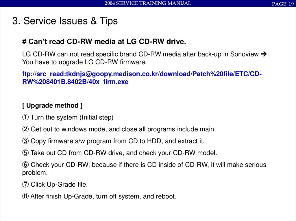
# Can’t read CD-RW media at LG CD-RW drive.
LG CD-RW can not read specific brand CD-RW media after back-up in Sonoview
You have to upgrade LG CD-RW firmware.
ftp://src_read:tkdnjs@goopy.medison.co.kr/download/Patch%20file/ETC/CDRW%208401B.8402B/40x_firm.exe
[ Upgrade method ]
① Turn the system (Initial step)
② Get out to windows mode, and close all programs include main.
③ Copy firmware s/w program from CD to HDD, and extract it.
⑤ Take out CD from CD-RW drive, and check your CD-RW model.
⑥ Check your CD-RW, because if there is CD inside of CD-RW, it will make serious
problem.
⑦ Click Up-Grade file.
⑧ After finish Up-Grade, turn off system, and reboot.
PAGE 19
20.
2004 SERVICE TRAINING MANUAL3. Service Issues & Tips
# SA9900 Sonoview file size
It is different by 2D image and 3D image.
1. 2D saved image
B/W : approximately 300KB / COLOR : approximately 900KB
2. 3D saved image
It is different by ROI BOX size. Approximately 10MB.
3. 3D CINE
Not fix.
PAGE 20
21.
2004 SERVICE TRAINING MANUAL3. Service Issues & Tips
# VCR remote control
Only can use Panasonic MD830.
Because, this model has RS232C port.
You can use VCR remote control function by RS232C port.
[Setup] [Peripherals] Tab [Serial port] menu
You have to check “Com1 Panasonic MD 830” item.
It is impossible to use Sony SVO9500 MDP PAL with SA9900.
PAGE 21
22.
2004 SERVICE TRAINING MANUAL3. Service Issues & Tips
# SA9900 Cine saving method
1. Press “Freeze” key, and press number [6] of Hotkey.
PAGE 22
23.
2004 SERVICE TRAINING MANUAL3. Service Issues & Tips
# SA9900 Cine saving method
2. You can see Saving bar as like below picture.
PAGE 23
24.
2004 SERVICE TRAINING MANUAL3. Service Issues & Tips
# SA9900 Cine saving method
3. Press [Sonoview] key, and you can see saved cine file.
Select your saved cine file, and press [Export] key.
PAGE 24
25.
2004 SERVICE TRAINING MANUAL3. Service Issues & Tips
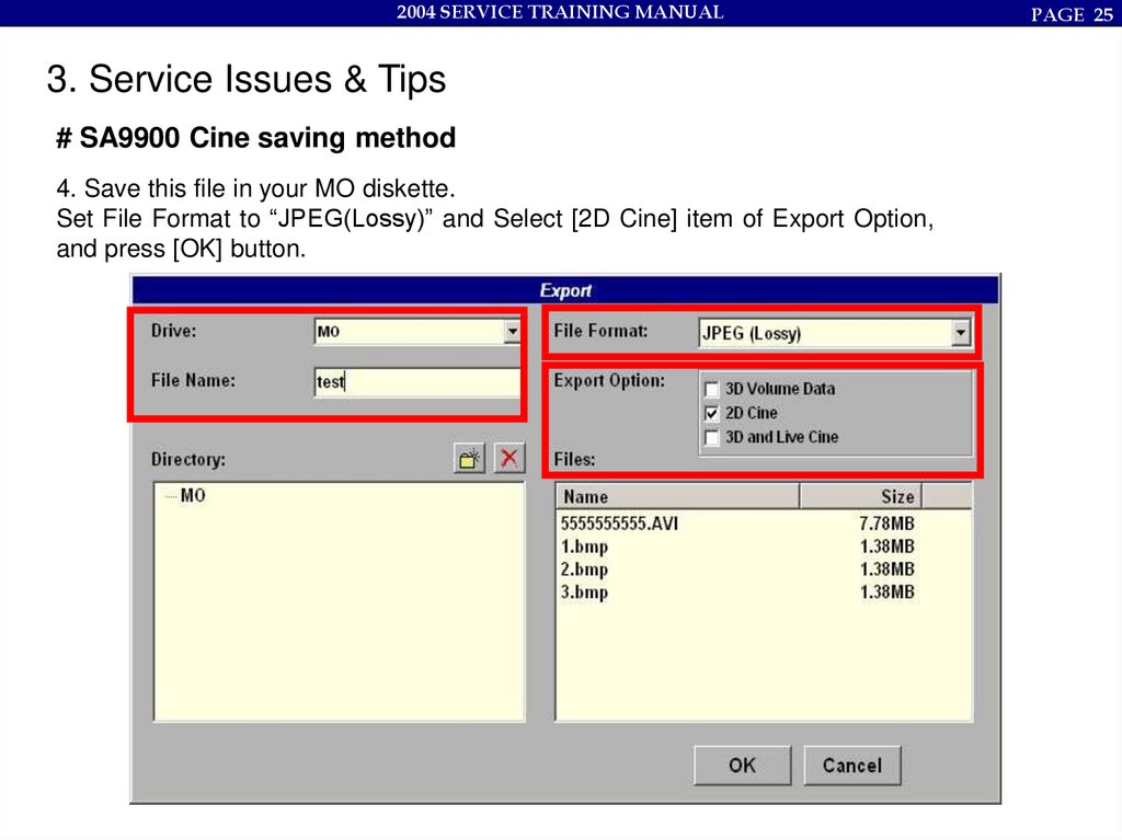
# SA9900 Cine saving method
4. Save this file in your MO diskette.
Set File Format to “JPEG(Lossy)” and Select [2D Cine] item of Export Option,
and press [OK] button.
PAGE 25
26.
2004 SERVICE TRAINING MANUAL3. Service Issues & Tips
# SA9900 Cine saving method
5. You can see saved cine file (avi file format) in your MO diskette.
PAGE 26
27.
2004 SERVICE TRAINING MANUAL3. Service Issues & Tips
# SA9900 Cine saving method
6. See cine image by windows Media Player
PAGE 27
28.
2004 SERVICE TRAINING MANUAL4. Trouble Shooting
1. B/C/D Doppler Noise : Beep sounds in strong Echo point or unfocused area
Change the Power Revision 08 to 09
2. 2-5EL Probe Color Noise : in C-mode, vertical color noise when set the color
filter to F3
Change the B/F Board Revision 3B to 3C
3. V4-7 Probe Color Noise : in C-mode, 4~5Khz PRF color noise occurs
Change the B/F Board Revision 3B to 3C
PAGE 28
29.
2004 SERVICE TRAINING MANUALPAGE 29
4. Trouble Shooting
# Error message
(1) Get out to 2D mode when use 3D mode with VAW4-7 probe. (It is only SA9900 Live
model)
(2) Appear “Error code 1”
Change Motor B/D to new revision.
P art No
Before Version
After Version
AY - 332- MOTOR/CNG
3A / 3B
3C
30.
2004 SERVICE TRAINING MANUALPAGE 30
4. Trouble Shooting
# System hang-up in patient ID input menu.
When you press patient ID button, the Alphanumeric keyboard is not working and system
hang-up.
Change keyboard Lamp invert board and Keyboard cable.
B e fo re
A fte r
Invert B /D
256-Z -003A
256-Z -004A
Keyboard cable
C B L-332-N /KB
C B L-332-N /KB -2
Old cable
New cable
31.
2004 SERVICE TRAINING MANUAL4. Trouble Shooting
# Stop Booting bar 78%, and appear below error message.
CHECK DSC READY ERROR , ERROR=2054
It is problem by DSC ADSP handshaking. So, it is DSC board problem.
PAGE 31
32.
2004 SERVICE TRAINING MANUAL4. Trouble Shooting
# Appear below error message during booting, and hang-up system.
Failed to init Keypanel
It can suspect two problems.
One is Keypanel problem. In this case you have to change Key I/F board.
The other is S/W problem. In this case, you have to use ghost CD.
PAGE 32
33.
2004 SERVICE TRAINING MANUAL4. Trouble Shooting
# Appear Noise in Doppler mode when using PB-EC4-9/10ED
This problem appear only the third probe port
Change CW board
PAGE 33
34.
2004 SERVICE TRAINING MANUAL4. Trouble Shooting
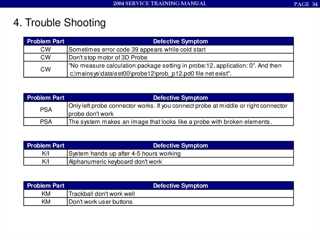
Problem Part
Defective Symptom
CW
Sometimes error code 39 appears while cold start
CW
Don't stop motor of 3D Probe
"No measure calculation package setting in probe:12, application: 0". And then
CW
c;\mainsys\data\set00\probe12\prob_p12.pd0 file net exist".
Problem Part
PSA
PSA
Defective Symptom
Only left probe connector works. If you connect probe at middle or right connector
probe don't work
The system makes an image that looks like a probe with broken elements.
Problem Part
Defective Symptom
K/I
System hands up after 4-5 hours working
K/I
Alphanumeric keyboard don't work
Problem Part
KM
Trackball don't work well
KM
Don't work user buttons
Defective Symptom
PAGE 34
35.
2004 SERVICE TRAINING MANUAL4. Trouble Shooting
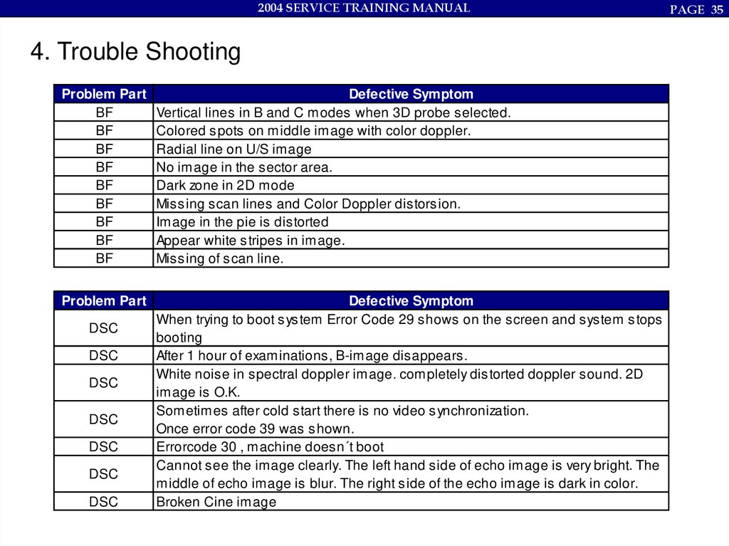
Problem Part
BF
BF
BF
BF
BF
BF
BF
BF
BF
Defective Symptom
Vertical lines in B and C modes when 3D probe selected.
Colored spots on middle image with color doppler.
Radial line on U/S image
No image in the sector area.
Dark zone in 2D mode
Missing scan lines and Color Doppler distorsion.
Image in the pie is distorted
Appear white stripes in image.
Missing of scan line.
Problem Part
Defective Symptom
When trying to boot system Error Code 29 shows on the screen and system stops
booting
After 1 hour of examinations, B-image disappears.
White noise in spectral doppler image. completely distorted doppler sound. 2D
image is O.K.
Sometimes after cold start there is no video synchronization.
Once error code 39 was shown.
Errorcode 30 , machine doesn´t boot
Cannot see the image clearly. The left hand side of echo image is very bright. The
middle of echo image is blur. The right side of the echo image is dark in color.
Broken Cine image
DSC
DSC
DSC
DSC
DSC
DSC
DSC
PAGE 35
36.
2004 SERVICE TRAINING MANUAL4. Trouble Shooting
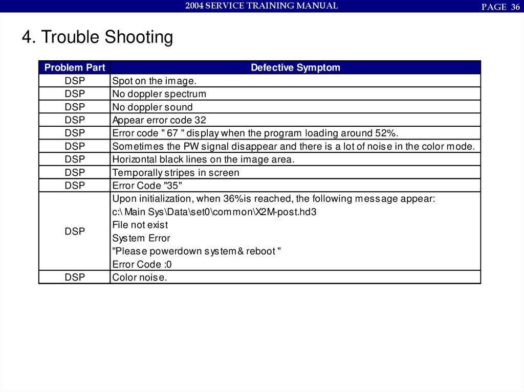
Problem Part
DSP
DSP
DSP
DSP
DSP
DSP
DSP
DSP
DSP
DSP
DSP
Defective Symptom
Spot on the image.
No doppler spectrum
No doppler sound
Appear error code 32
Error code " 67 " display when the program loading around 52%.
Sometimes the PW signal disappear and there is a lot of noise in the color mode.
Horizontal black lines on the image area.
Temporally stripes in screen
Error Code "35"
Upon initialization, when 36%is reached, the following message appear:
c:\ Main Sys\Data\set0\common\X2M-post.hd3
File not exist
System Error
"Please powerdown system& reboot "
Error Code :0
Color noise.
PAGE 36
37.
2004 SERVICE TRAINING MANUAL4. Trouble Shooting
Problem Part
Defective Symptom
PC
Don't identify HDD.
PC
System dosn`t start. Only Self test on the monitor.
Hangs up after long time of running.
PC
After hanging, there is no reaction on any button pressing.
PC
When you get in BIOS System is stopped.
System hangs up. This frozen is only in 3D-mode after starting of 3D-aquisition by
PC
93% of whole process. Allways by this 93%. If the machine have 40 minutes
pause in the day, than this frozen are not too often.
Problem Part
Defective Symptom
MOTOR
Error message " error 85" with 3D probe.
MOTOR
The system gets out to 2D mode from 3D mode.
MOTOR
Not operating Live 3D
PAGE 37
38.
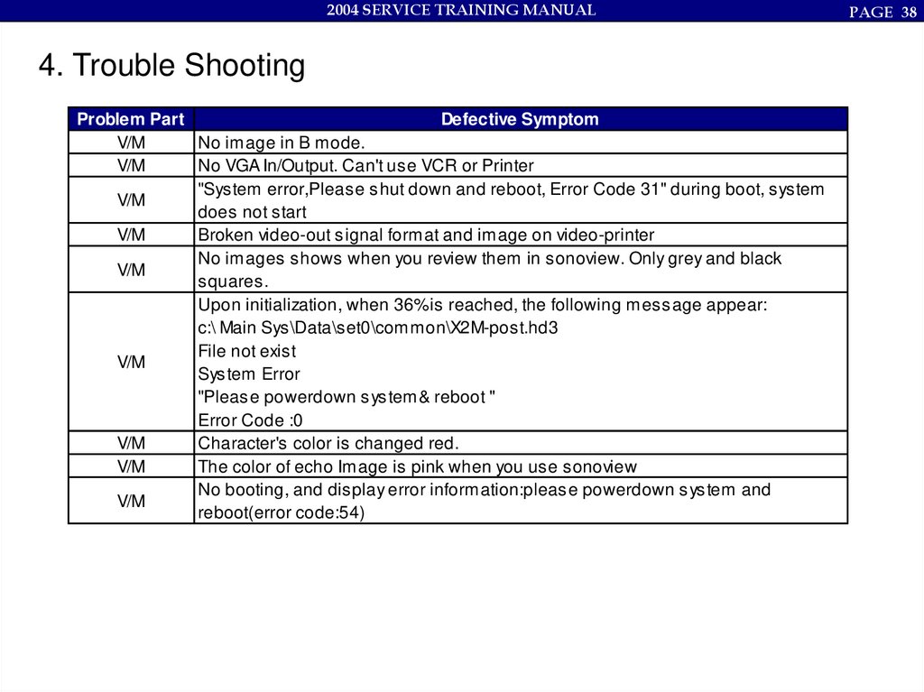
2004 SERVICE TRAINING MANUAL4. Trouble Shooting
Problem Part
Defective Symptom
V/M
No image in B mode.
V/M
No VGA In/Output. Can't use VCR or Printer
"System error,Please shut down and reboot, Error Code 31" during boot, system
V/M
does not start
V/M
Broken video-out signal format and image on video-printer
No images shows when you review them in sonoview. Only grey and black
V/M
squares.
Upon initialization, when 36%is reached, the following message appear:
c:\ Main Sys\Data\set0\common\X2M-post.hd3
File not exist
V/M
System Error
"Please powerdown system& reboot "
Error Code :0
V/M
Character's color is changed red.
V/M
The color of echo Image is pink when you use sonoview
No booting, and display error information:please powerdown system and
V/M
reboot(error code:54)
PAGE 38